Placa PC Chip M909
64
i Motherboard User’s Guide This publication, including photographs, illustrations and software, is under the protection of international copyright laws, with all rights reserved. Neither this manual, nor any of the material contained herein, may be reproduced without the express written consent of the manufacturer. The information in this document is subject to change without notice. The manufacturer makes no representations or warranties with respect to the contents hereof and specifically disclaims any implied warranties of merchantability or fitness for any particular purpose. Further, the manufacturer reserves the right to revise this publication and to make changes from time to time in the content hereof without obligation of the manufacturer to notify any person of such revision or changes. Trademarks IBM, VGA, and PS/2 are registered trademarks of International Business Machines. Intel, Pentium II/III, Pentium 4, Celeron and MMX are registered trademarks of Intel Corporation. Microsoft, MS-DOS and Windows 98/ME/NT/2000/XP are registered trademarks of Microsoft Corporation. PC-cillin is a trademark of Trend Micro Inc. AMI is a trademark of American Megatrends Inc. It has been acknowledged that other brands or product names in this manual are trademarks or the properties of their respective owners. Copyright © 2004 All Rights Reserved M909G Series, V5.0 I845/August 2004 Downloaded from www.Manualslib.com manuals search engine
description
Manual de Placa PC Chip M909g Pentium 4
Transcript of Placa PC Chip M909

i
Motherboard User’s Guide
This publication, including photographs, illustrations and software,is under the protection of international copyright laws, with allrights reserved. Neither this manual, nor any of the materialcontained herein, may be reproduced without the express writtenconsent of the manufacturer.The information in this document is subject to change withoutnotice. The manufacturer makes no representations or warrantieswith respect to the contents hereof and specifically disclaims anyimplied warranties of merchantability or fitness for any particularpurpose. Further, the manufacturer reserves the right to revise thispublication and to make changes from time to time in the contenthereof without obligation of the manufacturer to notify any personof such revision or changes.
TrademarksIBM, VGA, and PS/2 are registered trademarks of InternationalBusiness Machines.Intel, Pentium II/III, Pentium 4, Celeron and MMX are registeredtrademarks of Intel Corporation.Microsoft, MS-DOS and Windows 98/ME/NT/2000/XP areregistered trademarks of Microsoft Corporation.PC-cillin is a trademark of Trend Micro Inc.AMI is a trademark of American Megatrends Inc.It has been acknowledged that other brands or product names inthis manual are trademarks or the properties of their respectiveowners.
Copyright © 2004All Rights ReservedM909G Series, V5.0
I845/August 2004
Downloaded from www.Manualslib.com manuals search engine

ii
Motherboard User’s Guide
Table of ContentsTrademark ................................................................................... i
Static Electricity Precautions ............................................................ iiiPre-Installation Inspection ................................................................ iiiFeatures and Checklist Translation .................................................... v
Chapter 1: Introduction ............................................................ 1Key Features ........................................................................................ 2Package Contents ................................................................................ 5
Chapter 2: Motherboard Installation ..................................... 6Motherboard Components ................................................................... 7I/O Ports ............................................................................................... 8Installing the Processor ....................................................................... 9Installing Memory Modules ............................................................... 10Jumper Settings .................................................................................. 12Install the Motherboard ..................................................................... 13Connecting Optional Devices ............................................................ 14Install Other Devices .......................................................................... 17Expansion Slots .................................................................................. 20
Chapter 3: BIOS Setup Utility ............................................... 29Running the Setup Utility .................................................................. 30Standard CMOS Setup Page ............................................................. 31Advanced Setup Page ........................................................................ 32Features Setup Page .......................................................................... 33Power Management Setup Page ........................................................ 35PCI/Plug and Play Setup Page .......................................................... 37Load Optimal Settings ....................................................................... 38Load Best Performance Settings ........................................................ 38Features Setup Page .......................................................................... 39CPU PnP Setup Page ......................................................................... 41Hardware Monitor Page .................................................................... 42Change Password and Exit ................................................................ 43
Chapter 4: Software & Applications ..................................... 44Installing Support Software ............................................................... 45Bundled Software Installation ........................................................... 47Hyper- Threading CPU ...................................................................... 48
Dual Monitor................................................................................................23
Downloaded from www.Manualslib.com manuals search engine

iii
Motherboard User’s Guide
Static Electricity PrecautionsStatic electricity could damage components on this motherboard.Take the following precautions while unpacking this motherboardand installing it in a system.1. Don’t take this mainboard and components out of their
original static-proof package until you are ready to installthem.
2. While installing, please wear a grounded wrist strap ifpossible. If you don’t have a wrist strap, discharge staticelectricity by touching the bare metal of the system chassis.
3. Carefully hold this motherboard by its edges. Do not touchthose components unless it is absolutely necessary. Put thismotherboard on the top of static-protection package withcomponent side facing up while installing.
Pre-Installation Inspection1. Inspect this mainboard whether there are any damages to
components and connectors on the board.2. If you suspect this mainboard has been damaged, do not
connect power to the system. Contact your motherboardvendor about those damages.
Downloaded from www.Manualslib.com manuals search engine

iv
Motherboard User’s Guide
Notice:
Owing to Microsoft’s certifying schedule is various to every supplier, we might have some drivers not certified yet by Microsoft. Therefore, it might happen under Windows XP that a dialogue box (shown as below) pop out warning you this software has not passed Windows Logo testing to verify its compatibility with Windows XP. Please rest assured that our RD department has already tested and verified these drivers. Just click the “Continue Anyway” button and go ahead the installation.
Downloaded from www.Manualslib.com manuals search engine

v
Motherboard User’s GuideTraduction des Caractéristiques & Liste de contrôle
Liste de contrôleLe coffret de votre carte mère contient les éléments suivants :
• La carte mère• Le Manuel utilisateur• Un câble plat pour lecteur de disquette (optionnel)• Une câble plat pour lecteur IDE• CD de support de logiciels
CaractéristiquesPrise en charge du Processeur Socket-478
• Supporte le CPU Intel Pentium 4 series avec/sans la Technologie Hyper- Threading
• Supporte un Bus Avant allant jusqu’à 533/400 MHz
Chipset Le chipset Intel 845GV/GL contient le Hub de Contrôleur de Mémoire Intel 82845 et le Hub (ICH4) de Contrôleur d’E/S Intel 82801DB I/O conformément à une architecture novatrice et dimensionnable avec une fiabilité et des performances prouvées. Voici une liste de l’organisation des chipset et de leurs caractéristiques respectives :
Support de Mémoire
Le carte mère possède les caractéristiques suivantes :
AC’97 Codec
Logements d’Extension
• Conforme aux spécifications AC’97 2.3• Codec Full-duplex avec vitesse d’échantillonnage indépendante et variable• Mémoire tampon d’Ecouteurs Intégrée, SNR jusqu’à 90db• 6Ch DAC, supporte 6 canaux de sorties haut-parleurs• Support de gestion d’alimentation avancée
• Un logement AGPro (reportez-vous à la page 20 pour plus de détails)• Trois slots PCI 32 bits• Un slot CNR (Communications and Networking Riser)• Supporte maîtrise de bus Ultra DMA IDE avec vitesse de transfert de 100/ 66/33 Mo/sec
Northbridge845GV
845GL
Fonction Supporte: CPU FSB: 533/400MHz Technologie Hyper-Threading DDR333/266; USB2.0; Ultra ATA 100/66/33 Supporte:CPU FSB: 533*/400MHz DDR266; USB2.0; Ultra ATA 100/66/33
Ne supporte pas: Technologie Hyper-Threading *: Surfréquençage
• Deux logements DIMM 184 broches pour DDR SDRAM modules mémoire• Supporte les DDR jusqu’à 333MHz (845GV) ou le bus mémoire DDR266MHz
(845GL)• La mémoire maximum installée est 2Go
Downloaded from www.Manualslib.com manuals search engine

vi
Motherboard User’s Guide
vii
Motherboard User’s GuidePorts E/S InternesLa carte mère possède un jeu complet de ports d’E/S et de connecteurs:
• Deux ports PS/2 pour souris et clavier• Un port série• Un port VGA• Un port parallèle • Six ports USB (quatre ports fond de panier, prises USB internes offrant deux
ports supplémentaires)— USB2.0• Prises audio pour microphone, ligne d’entrée et ligne de sortie
LAN Fast Ethernet (optionnel)• Supporte le fonctionnement en 10/100Mb/s• Fast Ethernet MAC Intégré • Contrôleur Fast Ethernet à simple puce de bus local PCI • Compatible à PCI Revision 2.2 • Supporte la gestion d’alimentation ACPI, PCI• Conforme au standard PC99/PC2001• Supporte un temporisateur général 32 bits avec l’horloge PCI externe comme
source d’horloge, pour générer l’interruption de temporisation• Supporte le Contrôle de Flux Full Duplex (IEEE 802.3x)
USB 2.0
• Inclus trois contrôleurs d’hôte UHCI prenant en charge six ports externes• Nouveau: Inclus un Contrôleur d’Hôte USB 2.0 haute vitesse EHCI prenant en
charge les six ports• Nouveau: Prend en charge un port de débogage à haute vitesse USB 2.0• Prend en charge l’éveil à partir des états de veille S1-S5• Prend en charge le logiciel de clavier/souris patrimonial
Downloaded from www.Manualslib.com manuals search engine

vii
Motherboard User’s Guide Funktionen & Checkliste
ChecklisteDie Verpackung Ihres Motherboards enthält folgende Teile:• Motherboard• Handbuch• Bandkabel für Floppylaufwerke (optional)• Bandkabel für IDE-Laufwerke• Software -CD
AusstattungUnterstütz Socket-478-Prozessoren• Unterstützung für Intel Pentium 4-CPUs mit/ohne “Hyper-Threading”-Tech-
nologie • Unterstützung von bis zu 533/400 MHz Front-Side Bus
ChipsatzDer Intel 845GV/GL-Chipsatz verfügt über den Intel 82845 Memory Control Hub und den Intel 82801DB I/O Controller Hub (ICH4). Die Chipsatzarchitektur ist in einem innovativen und skalierbaren Design gehalten und verspricht sowohl Zuverlässigkeit als auch Leistungsstärke. Unten stehend finden Sie eine Liste mit den Chipsatzteilen und deren jeweiligen Funktionen:
Speicherunterstützung
Das Motherboard verfügt über die folgenden Erweiterungsoptionen:
Funktion Unterstützung für :CPU FSB: 533/400MHz “Hyper-Threading” -Technologie DDR333/266; USB2.0; Ultra ATA 100/66/33 Unterstützung für :CPU FSB: 533*/400MHz DDR266; USB2.0; Ultra ATA 100/66/33
Keine Unterstützung für : “Hyper-Threading” -Technologie *: Over-Clocking
Northbridge845GV
845GL
AC’97 Codec
Erweiterungssteckplätze
• Entspricht AC’97 2.3• Vollduplex-Codec mit unabhängiger und variabler Abtastrate• Integrierter Kopfhörer-Buffer, SNR bis zu 90db• 6Ch DAC, unterstützt 6-Kanal-Lautsprecherausgang• Unterstützung für Advanced Power Management
• Ein AGPro-Slot (siehe Seite 20 für mehr Details)• Drei 32-Bit PCI-Steckplätze• Ein CNR-Steckplatz (Communications and Networking Riser)• Unterstützung für IDE Ultra DMA-Busmastering mit Transferraten von 100/66/
33 MB/Sek
• Zwei 184-pin DIMM Steckplätze für DDR SDRAM Speichermodule• Unterstützung für DDR bis zu 333MHz (845GV) oder DDR266MHz (845GL)
Speicherbus• Maximal auf 2GB Speicher erweiterbar
Downloaded from www.Manualslib.com manuals search engine

viii
Motherboard User’s Guide
vii
Motherboard User’s GuideOnboard I/O-SteckplätzeDas Motherboard verfügt über einen kompletten Satz von I/O-Steckplätze und Anschlüssen:
• Zwei PS/2-Steckplätze für Maus und Tastatur yboard • Ein serieller Steckplatz• Ein VGA-Steckplatz • Ein paralleler Steckplatz• Sechs USB Ports (vier Ports an der Rückseite, onboard USB-Köpfe, welche zwei weitere Ports bieten)-USB2.0• Audioanschlüsse für Mikrofon, line-in und line-out
Fast Ethernet LAN (optional)• Unterstützt Betrieb mit 10/100 Mb/Sek. • Integriertes Fast Ethernet MAC • PCI Local Bus Single-Chip Fast Ethernet-Controller
• Kompatibel mit PCI Revision 2.2 • Unterstützung für ACPI, PCI Power Management
• Kompatibilität mit den standard PC99/PC2001• Unterstützung für einen 32-Bit General-Purpose Timer, dem der externe PCI- Takt als Taktquelle zur Erzeugung des Timer-Interrupt dient• Unterstützung für Vollduplex-Flusskontrolle (IEEE 802.3x)
USB 2.0 • Mit drei UHCI Host-Controller, welche sechs externe Ports unterstützen• Neu: Mit einem EHCI High-Speed (Hochgeschwindigkeits)-USB 2.0 Host- Controller welcher alle sechs Ports unterstützt• Neu: Unterstützt einen USB 2.0 High-Speed Debug-Port• Aufweckungsunterstützung des Stillstadiums S1-S5• Unterstützung von Tastatur/Maus-Software
Downloaded from www.Manualslib.com manuals search engine

ix
Motherboard User’s GuideTraduzione Funzioni e Lista
ListaL’imballo della scheda madre é composto da:• La scheda madre• Il manuale• Una piattina per il collegamento dei drive (opzionale)• Una piattina IDE • Il CD con il Software di supporto
CaratteristicheDotata di Socket-478 per Processori
• Supporta CPU Intel Pentium serie 4 con/senza Tecnologia Hyper-Threading
• Supporta fino a 533/400 MHz Front Side BusChipsetl chipset Intel 845GV/GL incorpora il Hub di controllo memIoria Intel 82845 a il Hub (ICH4) di controllo I/O Intel 82801DB in conformità ad un’architettura innovativa e scalabile dalle prestazioni e affidabilità dimostrate. Segue una lista con i chipset e le rispettive funzioni:
AC’97 Codec
Opzioni di espansione
• Conforme con le specifiche AC`97 2.3• Codec full-duplex con frequenza di campionamento indipendente e variabile• Memoria tampone integrata per auricolare, SNR fino a 90db• 6 CanDAC, supporto di 6 uscite per le casse• Supporto per gestione energetica avanzata.
• Uno slot AGPro (fare riferimento alla pagina 20 per ulteriori dettagli)• Tre slot a 32-bit PCI • Uno slot CNR (Communications and Networking Riser)• Supporta gestione di canali IDE Ultra DMA con percentuali di campionamento
di 100/66/33/MB/sec.
• Due slot DIMM a 184 pin per moduli di memoria DDR SDRAM• Supporta DDR fino a 333MHz (845GV) o bus di memoria DDR266MHz
(845GL)• Quantità massima di memoria installabile, 2GB
Memoria Supporta
La scheda madre dotata delle seguenti opzioni di espansione:
Funzione Supporta: CPU FSB: 533/400MHz Tecnologia Hyper-Threading DDR333/266;USB2.0; Ultra ATA 100/66/33 Supporta: CPU FSB: 533*/400MHz DDR266 ; USB2.0; Ultra ATA 100/66/33 Non supporta: Tecnologia Hyper-Threading
*: Overclocking
Northbridge845GV
845GL
Downloaded from www.Manualslib.com manuals search engine

x
Motherboard User’s Guide
vii
Motherboard User’s GuideOnboard I/O PortaLa scheda madre è dotata da una serie completa di porte e connettori I/O:
• Due porte PS/2 per tastiera e mouse• Una porta seriale• Una porta VGA• Una porta parallela• Sei porte USB (quattro porte sul pannello posteriore; installati due headers USB che consentono di avere due porte supplementari)-USB2.0• Jack audio per microfono, ingresso linea e uscita linea
Fast Ethernet LAN (supplementare)• Supporto delle operazioni 10/100Mbps• Fast Ethernet MAC integrato • Controller Fast Ethernet PCI con chip singolo
• Conforme a PCI Revisione 2.2• Supporta risparmio energetico ACPI, PCI
• Conforme allo standard PC99/PC2001• Supporta un timer per uso universale a 32-bit con clock PCI esterno come sorgente clock per generare gli interrupt da timer.• Supporta controllo di flusso Full Duplex (IEEE 802.3x)
USB 2.0• Include tre host controller UHCI che supportano sei porte esterne• Nuovo: include un host controller USB 2.0 EHCI ad alta velocità in grado di supportare tutte e sei le porte• Nuovo: supporta una porta di debug USB 2.0 ad alta velocità• Supporta wake-up dallo stato di risveglio (sleeping) S1-S5• Supporta software legacy per tastiera/mouse
Downloaded from www.Manualslib.com manuals search engine

xi
Motherboard User’s GuideTraducción de Características & Lista
LISTA DE VERIFICACIÓNEl paquete de su placa principal contiene los sigtes. ítems:
• La placa principal• El Manual del Usuario• Un cable cinta para el lector de disquete (optativo)• Un cable cinta para el lector IDE • CD de Software de soporte
CaracterísticasSoporte de Procesador Socket-478
• Soporta CPU de Intel Pentium 4 con/sin la Tecnología Hyper -Threading• Soporta hasta Bus de Lado Frontal de 533/400 MHz
ChipsetEl chipset Intel 845GV/GL contiene Hub de Controlador de Memoria Intel 82845 y Hub (ICH4) de Controlador Intel 82801DB I/O según una arquitectura innovadora y escalable con la fiabilidad y rendimiento aprobados. He aquí una lista del arreglo del chipset y sus respectivas características:
Función Soporta: CPU FSB: 533/400MHz Tecnología Hyper-Threading DDR333/266; USB2.0; Ultra ATA 100/66/33 Soporta: CPU FSB: 533*/400MHz DDR266 ; USB2.0; Ultra ATA 100/66/33 No soporta: Tecnología Hyper-Threading *: Sobre-cronometraje
Northbridge845GV
845GL
AC’97 Codec
Ranuras de Expansión
• Conforme con la especificación AC’97 2.3• Full-duplex Codec con índice de muestreo independiente y variable • Buffer de Audífono Incorporado, SNR hasta 90db• 6Ch DAC, soporte de altoparlante de 6 canales• Soporte de administración de energía avanzada
• Una ranura AGPro (refiera a la pg 20 para más detalles)• Tres ranuras 32-bit PCI • Una ranura CNR (Communications and Networking Riser)• Soporta mastering de bus IDE Ultra DMA con índices de transferencia de
100/66/33 MB/seg
• Dos ranuras 184-pin DIMM para módulos de memoria DDR SDRAM• Soporta DDR hasta bus de memoria de 333MHz (845GV) o DDR266MHz
(845GL)• Memoria máxima instalada es 2GB
Soporte de Memoria
La placa principal viene con las sigtes. opciones de expansión:
Downloaded from www.Manualslib.com manuals search engine

xii
Motherboard User’s Guide
vii
Motherboard User’s GuidePuertos I/O AbordosLa placa principal tiene un juego completo de puertos I/O y conectores:
• Dos puertos PS/2 para ratón y teclado• Un puerto serial• Un puerto VGA• Un puerto paralelo• Seis puertos USB (cuatro puertos del panel trasero, los cabezales USB abordo provee dos puertos extras)-USB2.0• Clavijas de sonido para micrófono, entrada y salida de línea
Fast Ethernet LAN (optativo)• Soporta la operación de 10/100Mbps• Fast Ethernet MAC Integrado• Controlador de Fast Ethernet de chip singular de bus local PCI
• Conforme con PCI Revisión 2.2 • Soporta administración de suministro ACPI, PCI
• Conforme con la norma PC99/PC2001• Soporta un cronómetro de todo propósito 32-bit con el reloj PCI externo como fuente de reloj, para generar interrupción de cronómetro• Soporta Control de Flujo Full Duplex (IEEE 802.3x)
USB 2.0• Incluye tres controladores anfitriones UCHI que soporta seis puertos externos • Nuevo: Incluye un Controlador Anfistrión USB 2.0 de EHCI alta velocidad que soporta todos los seis puertos • Nuevo: Soporta un puerto de debug de USB 2.0 alta velocidad • Soporta despertar de los estados de dormir S1-S5• Soporta software teclado/ratón de legado
Downloaded from www.Manualslib.com manuals search engine

xiii
Motherboard User’s GuideTradução da Lista & Características
Lista de verificaçãoA embalagem da sua placa principal contém os seguintes itens:
• A placa principal• O Manual do Utilizador• Um cabo para a unidade de disquetes (opcional)• Um cabo para a unidade IDE • CD de suporte para o software
CaracterísticasSuporte do Processador Socket-478
• Suporta CPU série Intel Pentium 4 com/sem Tecnologia Hyper-Threading • Suporta até 533/400 MHz Front-Side Bus
ChipsetHá chipsets Intel 845GV/GL contendo Intel 82845 Memory Controller Hub (ICH4) e Intel 82801DB I/O Controller Hub de acordo com uma arquitetura inovativa escalável com performance e confiabilidade comprovada. Aqui fica uma lista da organização do chipset e das respectivas características:
Função Suporta: CPU FSB: 533/400MHz Teconologia Hyper-Threading, DDR333/266 USB2.0; Ultra ATA 100/66/33 Suporta: CPU FSB: 533*/400MHz DDR266; USB2.0; Ultra ATA 100/66/33 Não suporta: Teconologia Hyper-Threading *: Overclocking
Northbridge845GV
AC’97 Codec
Slots de expansão
• Compatível com a especificação AC’97 2.3• Full-duplex Codec com razão de amostra variável independente• Buffer de Fone de Ouvido embutido, SNR até 90db• 6 canais DAC, suporta 6 canais de altifalantes• Suporte de gerenciamento de força avançado
• Uno slot AGPro (fare riferimento alla pagina 20 per ulteriori dettagli)• Três encaixes 32-bit PCI slots • Um encaixe para CNR (Communications and Networking Riser)• Suporta IDE Ultra DMA bus mastering com razão de transferência de 100/66/
33 MB/seg
• Dois sockets DIMM com 184 pinos para módulos de memória DDR SDRAM• Suporta no máximo DDR até 333MHz (845GV) ou bus de memória DDR266MHz (845GL)• A memória máxima instalada é de 2GB
Suporte de memória
A placa principal possui as seguintes slots de expansão:
845GL
Downloaded from www.Manualslib.com manuals search engine

xiv
Motherboard User’s Guide
vii
Motherboard User’s GuidePortas I/O na placaA placa principal possui um conjunto completo de portas e conectores I/O:
• Duas portas PS/2 para o rato e teclado• Uma porta série• Uma porta VGA• Uma porta paralela• Seis portas USB (quatro portas de painel de interconexão, suportes USB onboard fornecendo duas portas extra)-USB2.0• Jacks audio para microfone, line-in e line-out
Ethernet Rápida LAN (opcional)• Suporta o funcionamento 10/100Mb/s• Fast Ethernet MAC integrado • Controlador PCI bus local de chip único Fast Ethernet
• PCI Revision 2.2 complacente • Suporta gerenciamento de força ACPI, PCI
• Padrão PC99/PC2001 complacente• Suporta um cronômetro de 32-bit com propósito geral, relógio externo PCI como fonte do relógio, para gerar interrupção do cronômetro• Suporta Controle de Fluxo Full Duplex (IEEE 802.3x)
USB 2.0• Incluiu três controladores host UHCI que suportam seis portas externas• Novo: Incluiu um Controlador Host USB 2.0 de alta velocidade EHCI que suporta todas as seis portas• Novo: Suporta uma porta de depuração de alta velocidade USB 2.0• Suporta sistema de despertar de estados de adormecimento S1-S5• Suporta software herdado de teclado/rato
Downloaded from www.Manualslib.com manuals search engine

xv
Motherboard User’s Guide功能和检查单翻译
检查单您的主板包装含有以下项目:• 主板• 用户手册• 一根磁盘驱动器扁平电缆(可选)• 一根 IDE 驱动器扁平电缆 • 软件支持 CD
功能支持 Socket-478 处理器
• 支持带有/不带有多线程技术的 Intel Pentium 4 系列 CPU• 支持 533/400 MHz 前端总线
芯片组Intel 845GV/GL 芯片组包含 Intel 82845 存储控制器 Hub (ICH4)和 Intel 82801DB I/O 控制器 Hub,它基于一种新型的、可扩展的架构,能提供已经证明的可靠性和高性能。以下是芯片组和它们的功能:
AC'97 编解码器
扩展槽
• 兼容 AC’97 2.3 规格• 具有独立和可调采样速率的全双工编解码器
• 内建耳机缓冲,SNR 到 90db
• 6路DAC,支持6路扬声器输出。• 支持高级电源管理
• 1 个 AGPro 插槽(参见第 20 页获取详细信息)• 3个 32 位 PCI 扩展插槽• 一个通信网络转接 (CNR) 插槽• 支持 IDE Ultra DMA 总线控制,传输速率可达 100/66/33 MB/sec。
• 2个用于 DDR SDRAM 内存条的 184-pin DIMM 插槽• 支持 DDR 到 333MHz (845GV) 或 DDR266MHz (845GL)存储总线• 内存最多可达 2GB
内存支持
此主板提供如下扩展选项:
功能
支持: CPU FSB: 533/400MHz 多线程技术 DDR333/266; USB2.0; Ultra ATA 100/66/33
支持: CPU FSB: 533*/400MHz
DDR266; USB2.0; Ultra ATA 100/66/33
不支持:多线程技术
*: 超频
北桥845GV
845GL
Downloaded from www.Manualslib.com manuals search engine

xvi
Motherboard User’s Guide
vii
Motherboard User’s Guide集成 I/O 端口此主板具有完整的 I/O 端口和插孔:
• 2 个用于连接鼠标和键盘的 PS/2 端口
• 1 个串口
• 1 个 VGA 端口
• 1 个并口
• 6 个 USB 端口(主板后面板带 4 个接口,板上 USB 接口提供其它 2 个端 口)— USB2.0
• 麦克风、线入和线出声音插孔
快速以太网 LAN (可选)• 10 Mb/s 和 100 Mb/s 工作
• 集成高速以太网 MAC
• PCI 局域总线单芯片高速以太网控制器• 兼容 PCI 2.2 版本• 支持 ACPI,PCI 电源管理
• 符合 PC99/PC2001 标准
• 支持 32 位多用途定时器(带有外部 PCI 时钟作为时钟脉冲源),可以产生 定时中断
• 支持全双工流控制 (IEEE 802.3x)
USB 2.0• 包括 3 个UHCI 主控器,支持 6 个外部端口• 新功能:包括 1 个 EHCI 高速 USB 2.0 主控器,支持所有 6 个端口• 新功能:支持 1 个 USB 2.0 高速调试端口• 支持从休眠状态 S1-S5 的唤醒功能• 支持传统键盘/鼠标软件
Downloaded from www.Manualslib.com manuals search engine

1
Chapter 1: Introduction
Chapter 1 Introduction
This motherboard has a Socket-478 supporting Intel Pentium 4/Prescott with Hyper-Threading Technology processors withFront-Side Bus (FSB) speeds up to 533/400 MHz. Hyper-Threading Technology, designed to take advantage of themultitasking features in Windows XP, gives you the power to domore things at once.
Note: It supports Hyper-Threading Technology only when theIntel 845GV is installed. Intel 845GL supports FSB 533 MHzonly by overclocking.
This motherboard has the Intel 845GL/GV chipset that containsIntel 82845 Memory Controller Hub and Intel 82801 I/O Control-ler Hub. It supports built-in USB 2.0 providing higher bandwidth.It implements Universal Serial Bus Specification Revision 2.0and includes three UHCI host controllers that support six externalports. This motherboard supports AC’ 97 audio codec andprovides Ultra DMA 100/66/33 function.
This motherboard has one CNR (Communications and Network-ing Riser), three 32-bit PCI slots and one AGPro slot. There is afull set of I/O ports including two PS/2 ports for mouse andkeyboard and audio jacks for microphone, line-in and line-out.There are one serial port, one VGA port, one parallel port, oneLAN port(optional), and six USB ports (USB2.0)–four back-panel ports and onboard USB header USB3 providing two extraports by connecting the Extended USB Module to themotherboard.
This motherboard is a Micro ATX motherboard that uses a 4-layer printed circuit board and measures 244 x 220mm.
Downloaded from www.Manualslib.com manuals search engine
2
Motherboard User’s Guide
Key Features
The key features of this motherboard include:
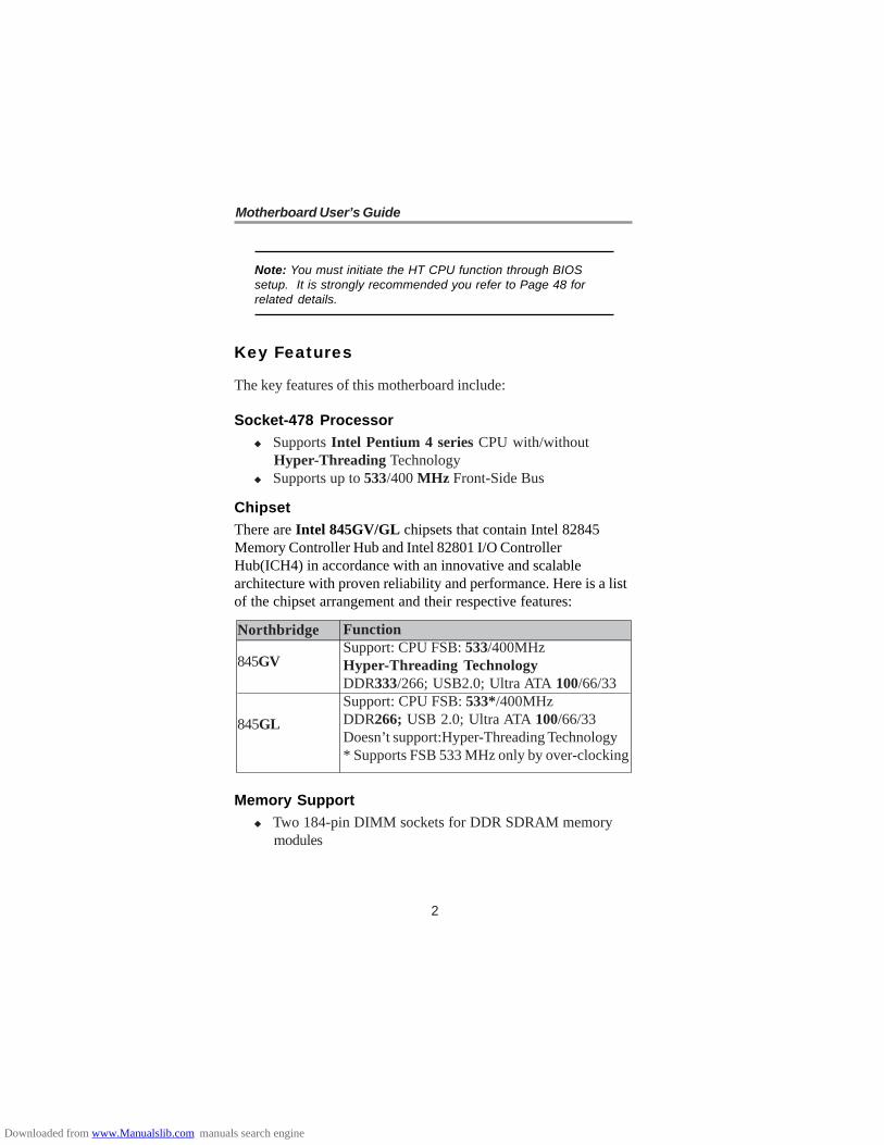
Socket-478 ProcessorSupports Intel Pentium 4 series CPU with/withoutHyper-Threading TechnologySupports up to 533/400 MHz Front-Side Bus
ChipsetThere are Intel 845GV/GL chipsets that contain Intel 82845Memory Controller Hub and Intel 82801 I/O ControllerHub(ICH4) in accordance with an innovative and scalablearchitecture with proven reliability and performance. Here is a listof the chipset arrangement and their respective features:
Memory SupportTwo 184-pin DIMM sockets for DDR SDRAM memorymodules
Note: You must initiate the HT CPU function through BIOSsetup. It is strongly recommended you refer to Page 48 forrelated details.
FunctionSupport: CPU FSB: 533/400MHzHyper-Threading TechnologyDDR333/266; USB2.0; Ultra ATA 100/66/33Support: CPU FSB: 533*/400MHzDDR266; USB 2.0; Ultra ATA 100/66/33Doesn’t support:Hyper-Threading Technology* Supports FSB 533 MHz only by over-clocking
Northbridge
845GV
845GL
Downloaded from www.Manualslib.com manuals search engine

3
Chapter 1: Introduction
Support DDR up to 333MHz (845GV) or DDR266MHz(845GL) memory busMaximum installed memory is 2GB
AC’97 CodecCompliant with AC’97 2.3 specificationFull-duplex Codec with independent and variable samplingrateEarphone Buffer Built-In, SNR up to 90db6Ch DAC, support 6-channel speak-outAdvanced power management support
Expansion Options
The motherboard comes with the following expansion options:One AGPro slot (refer to page 20 for more details)Three 32-bit PCI slotsOne CNR (Communications and Networking Riser) slotSupport IDE Ultra DMA bus mastering with transfer ratesof 100/66/33 MB/sec
Onboard I/O PortsThe motherboard has a full set of I/O ports and connectors:
Two PS/2 ports for mouse and keyboardOne serial portOne VGA portOne parallel portSix USB 2.0 ports (four back-panel and onboard USBheader providing two extra ports)Audio jacks for microphone, line-in and line-out
Fast Ethernet LAN (optional)10 Mb/s and 100 Mb/s operationIntegrated Fast Ethernet MACPCI local bus single-chip Fast Ethernet controller−Compliant to PCI Revision 2.2−Supports ACPI, PCI power management
Downloaded from www.Manualslib.com manuals search engine

4
Motherboard User’s Guide
Compliant to PC99/PC2001 standardSupports a 32-bit general-purpose timer with the externalPCI clock as clock source, to generate timer-interruptSupports Full Duplex Flow Control (IEEE 802.3x)
USB 2.0Includes three UHCI host controllers that support sixexternal portsNew: Includes one EHCI high-speed USB 2.0 Host Con-troller that supports all six portsNew: Supports a USB 2.0 high-speed debug portSupports wake-up from sleeping states S1-S5Supports legacy keyboard/mouse software
BIOS Firmware
This motherboard uses AMI BIOS that enables users to configuremany system features including the following:
Power managementWake-up alarmsCPU parameters and memory timingCPU and memory timing
The firmware can also be used to set parameters for differentprocessor clock speeds.
Bundled SoftwarePC-Cillin provides automatic virus protection underWindows 98/ME/NT/2000/XPAdobe Acrobat Reader is the software to help users readPDF files.
DimensionsMicro ATX form factor of 244 x 220mm
Downloaded from www.Manualslib.com manuals search engine

5
Chapter 1: Introduction
Package Contents
Your motherboard package contains the following items:The motherboardThe User’s GuideOne diskette drive ribbon cable (optional)One IDE drive ribbon cableSoftware support CD
Optional Accessories
You can purchase the following optional accessories for thismotherboard.
Extended USB moduleCNR v.90 56K Fax/Modem card
Note: You can purchase your own optional accessories from thethird party, but please contact your local vendor on any issuesof the specification and compatibility.
Downloaded from www.Manualslib.com manuals search engine

6
Motherboard User’s Guide
Chapter 2 Motherboard Installation
To install this motherboard in a system, please follow theseinstructions in this chapter:
• Identify the motherboard components• Install a CPU• Install one or more system memory modules• Make sure all jumpers and switches are set correctly• Install this motherboard in a system chassis (case)• Connect any extension brackets or cables to headers/
connectors on the motherboard• Install peripheral devices and make the appropriate connec-
tions to headers/connectors on the motherboard
Note:1. Before installing this motherboard, make sure jumper JP2
is under Normal setting. See this chapter for informationabout locating JP2 and the setting options.
2. Never connect power to the system during installation;otherwise, it may damage the motherboard.
3. Please refer to details of the AGPro slot on page 20before installing an AGP graphics card.
Downloaded from www.Manualslib.com manuals search engine

7
Chapter 2: Motherboard Installation
Motherboard Components
PANEL1
Socket-478
CD1
DDR1/2
SPKR1
ATX1
CHS FAN
IDE2/1
AUDIO2
AGP1
IOPORTS
PW1
SIR1
JP2
FLOPPYPCI1-3 USB3CN R1
PLED1
LABEL COMPONENTSDDR1-2 Two 184-pin DDR SDRAM socketsIDE1/2 Primary/Secondary IDE connectorsATX1 Standard 4-Pin ATX Power connectorPW1 Standard 20-Pin ATX Power connectorUSB3 Front Panel USB headerFLOPPY Floppy Disk Drive connectorPANEL1 Front Panel Switch/LED headerCHS FAN System Fan connectorJP2 Clear CMOS jumperSPKR1 Speaker headerCD1 Analog Audio Input headerPLED1 Power-On indicator header
CPU FAN
Downloaded from www.Manualslib.com manuals search engine

8
Motherboard User’s Guide
LABEL COMPONENTSSIR1 Infrared Port headerPCI 1-3 32-bit PCI slotsAUDIO2 Front Panel Audio headerCPUFAN CPU Fan connectorCNR1 Communications Networking Riser slotAGP1 AGPro slot *See page 21 for details
I/O Ports
The illustration below shows a side view of the built-in I/O portson the motherboard.
(Optional)
PS/2 Mouse
PS/2 Keyboard
Parallel Port (LPT1)
Serial Port COM1
VGA PortLAN Port (optional)
USB PortsAudio Ports
Use the upper PS/2 port to connect a PS/2pointing device.Use the lower PS/2 port to connect a PS/2keyboard.Use the Parallel port to connect printers orother parallel communications devices.Use the COM port to connect serial devicessuch as mice or fax/modems. COM1 isidentified by the system as COM1.Use the VGA port to connect VGA devices.Connect an RJ-45 jack to the LAN port toconnect your computer to the Network.Use the USB ports to connect USB devices.Use the three audio ports to connect audiodevices. The first jack is for stereo Line-Insignal. The second jack is for stereo Line-Outsignal. The third jack is for Microphone.
Downloaded from www.Manualslib.com manuals search engine

9
Chapter 2: Motherboard Installation
Installing the Processor
This motherboard has a Socket 478 processor socket. Whenchoosing a processor, consider the performance requirements ofthe system. Performance is based on the processor design, theclock speed and system bus frequency of the processor, and thequantity of internal cache memory and external cache memory.
CPU Installation Procedure
Follow these instructions to install the CPU:
Socket-478
1
CPUFAN
pin1
1. Unhook the locking lever of the CPU socket. Pullthe locking lever away from the socket and raisingit to the upright position.
2. Match the pin1 corner marked as the beveled edgeon the CPU with the pin1 corner on the socket.Insert the CPU into the socket. Do not use force.
3. Push the locking lever down and hook it under thelatch on the edge of socket.
4. Apply thermal grease to the top of the CPU.5. Install the cooling fan/heatsink unit onto the CPU,
and secure them all onto the socket base.6. Plug the CPU fan power cable into the CPU fan
connector (CPUFAN) on the motherboard.
Downloaded from www.Manualslib.com manuals search engine

10
Motherboard User’s Guide
Installing Memory Modules
This motherboard accommodates two 184-pin 2.5V unbufferedDouble Data Rate SDRAM (DDR SDRAM) Dual Inline MemoryModule (DIMM) sockets, and supports up to 2.0 GB of333(845GV)/266/200 MHz DDR SDRAM.
DDR SDRAM is a type of SDRAM that supports data transferson both edges of each clock cycle (the rising and falling edges),effectively doubling the memory chip’s data throughput.
DDR1 DDR2
Downloaded from www.Manualslib.com manuals search engine

11
Chapter 2: Motherboard Installation
Memory Module Installation Procedure
These modules can be installed with up to 2 GB system memory.Refer to the following to install the memory module.
1. Push down the latches on both sides of the DIMMsocket.
2. Align the memory module with the socket. There is anotch on the DIMM socket that you can install theDIMM module in the correct direction. Match the cutouton the DIMM module with the notch on the DIMMsocket.
3. Install the DIMM module into the socket and press itfirmly down until it is seated correctly. The socket latchesare levered upwards and latch on to the edges of theDIMM.
4. Install any remaining DIMM modules.
Downloaded from www.Manualslib.com manuals search engine

12
Motherboard User’s Guide
Jumper Settings
Connecting two pins with a jumper cap is SHORT; removing ajumper cap from these pins, OPEN.
JP2: Clear CMOS Jumper
Use this jumper to clear the contents of the CMOS memory. Youmay need to clear the CMOS memory if the settings in the SetupUtility are incorrect and prevent your motherboard from operating.To clear the CMOS memory, disconnect all the power cables fromthe motherboard and then move the jumper cap into the CLEARsetting for a few seconds.
Function Jumper SettingNormal Short Pins 1-2Clear CMOS Short Pins 2-3
JP2
1
Downloaded from www.Manualslib.com manuals search engine

13
Chapter 2: Motherboard Installation
Connect the power connector from the power supply to the PW1connector on the motherboard. The ATX1 is a +12V connectorfor CPU Vcore power.
If there is a cooling fan installed in the system chassis, connect thecable from the cooling fan to the CHS FAN fan power connectoron the motherboard.
Connect the case switches and indicator LEDs to the PANEL1header.
Install the Motherboard
Install the motherboard in a system chassis (case). The board is aMicro-ATX size motherboard. You can install this motherboard inan ATX case. Make sure your case has an I/O cover platematching the ports on this motherboard.
Install the motherboard in a case. Follow the case manufacturer’sinstructions to use the hardware and internal mounting points onthe chassis.
PANEL11
ATX1
CHS FAN
1
PW11
Downloaded from www.Manualslib.com manuals search engine

14
Motherboard User’s Guide
Connecting Optional Devices
Refer to the following for information on connecting themotherboard’s optional devices:
SPKR1: Speaker Header
Connect the cable from the PC speaker to the SPKR1 header onthe motherboard.
Please refer to the following list of the PANEL1 pin assignments.
Pin Signal Pin Signal 1 HD_LED_P(+) 2 FP PWR/SLP(+) 3 HD_LED_N(-) 4 FP PWR/SLP(-) 5 RESET_SW_N(-) 6 POWER_SW_P(+) 7 RESET_SW_P(+) 8 POWER_SW_N(-) 9 RSVD_DNU 10 KEY
Pin Signal Pin Signal 1 SPKR 2 NC 3 GND 4 +5V
AUDIO21
1USB3
SPKR11
1PLED1
1
SIR1
Downloaded from www.Manualslib.com manuals search engine

15
Chapter 2: Motherboard Installation
USB3: Front Panel USB Header
The motherboard has USB ports installed on the rear edge I/Oport array. Additionally, some computer cases have USB ports atthe front of the case. If you have this kind of case, use auxiliaryUSB header USB3 to connect the front-mounted ports to themotherboard.
1. Locate the USB3 header on the motherboard.2. Plug the bracket cable onto the USB3 header.3. Remove a slot cover from one of the expansion slots on
the system chassis. Install an extension bracket in theopening. Secure the extension bracket to the chassis witha screw.
AUDIO2: Front Panel Audio Header
This header allows the user to install auxiliary front-orientedmicrophone and line-out ports for easier access.
Pin Signal Pin Signal1 AUD_MIC 2 AUD_GND3 AUD_MIC_BIAS 4 AUD_VCC5 AUD_FPOUT_R AUD_RET_R7 HP_ON 8 KEY9 AUD_FPOUT_L 10 AUD_RET_L
Pin Signal Pin Signal1 VERG_FP_USBPWR0 2 VERG_FP_USBPWR03 USB_FP_P0(-) 4 USB_FP_P1(-)5 USB_FP_P0(+) 6 USB_FP_P1(+)7 GROUND 8 GROUND9 KEY 10 USB_FP_OC0
6
Downloaded from www.Manualslib.com manuals search engine

16
Motherboard User’s Guide
PLED1: Power-On Indicator HeaderIf there is another power-on indicator LED installed in the systemchassis, connect the LED to the PLED1 header.
SIR1: Infrared Header
The infrared port allows the wireless exchange of informationbetween your computer and similarly equipped devices such asprinters, laptops, Personal Digital Assistants (PDAs), and othercomputers.
1. Locate the infrared port-SIR1 header on themotherboard.
2. If you are adding an infrared port, connect the ribboncable from the port to the SIR1 header and then securethe port to an appropriate place in your system chassis.
Pin Signal Pin Signal 1 NC KEY 3 +5V 4 GND 5 IRTX 6 IRRX
2
Pin Signal1 GROUND2 NC3 POWER
Downloaded from www.Manualslib.com manuals search engine

17
Chapter 2: Motherboard Installation
Install Other Devices
Install and connect any other devices in the system following thesteps below.
FLOPPY
Floppy Disk Drive
The motherboard ships with a floppy disk drive cable that cansupport one or two drives. Drives can be 3.5" or 5.25" wide, withcapacities of 360K, 720K, 1.2MB, 1.44MB, or 2.88MB.
Install your drives and connect power from the system powersupply. Use the cable provided to connect the drives to the floppydisk drive connector FLOPPY.
1
IDE1IDE2
1 1
Downloaded from www.Manualslib.com manuals search engine

18
Motherboard User’s Guide
IDE Devices
IDE devices include hard disk drives, high-density diskette drives,and CD-ROM or DVD-ROM drives, among others.
The motherboard ships with an IDE cable that can support one ortwo IDE devices. If you connect two devices to a single cable,you must configure one of the drives as Master and one of thedrives as Slave. The documentation of the IDE device will tell youhow to configure the device as a Master or Slave device. TheMaster device connects to the end of the cable.
Install the device(s) and connect power from the system powersupply. Use the cable provided to connect the device(s) to thePrimary IDE channel connector IDE1 on the motherboard.
If you want to install more IDE devices, you can purchase asecond IDE cable and connect one or two devices to the Second-ary IDE channel connector IDE2 on the motherboard. If youhave two devices on the cable, one must be Master and one mustbe Slave.
Downloaded from www.Manualslib.com manuals search engine

19
Chapter 2: Motherboard Installation
Analog Audio Input Header
If you have installed a CD-ROM drive or DVD-ROM drive, youcan connect the drive audio cable to the onboard sound system.
Pin Signal 1 CD IN L 2 GND 3 GND 4 CD IN R
When you first start up your system, the BIOS should automati-cally detect your CD-ROM/DVD drive. If it doesn’t, enter theSetup Utility and configure the CD-ROM/DVD drive that youhave installed. On the motherboard, locate the 4-pin header CD1.
CD1
1
Downloaded from www.Manualslib.com manuals search engine
20
Motherboard User’s Guide
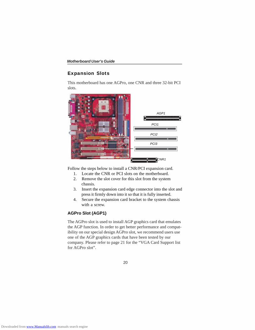
Expansion Slots
This motherboard has one AGPro, one CNR and three 32-bit PCIslots.
Follow the steps below to install a CNR/PCI expansion card.1. Locate the CNR or PCI slots on the motherboard.2. Remove the slot cover for this slot from the system
chassis.3. Insert the expansion card edge connector into the slot and
press it firmly down into it so that it is fully inserted.4. Secure the expansion card bracket to the system chassis
with a screw.
AGPro Slot (AGP1)
The AGPro slot is used to install AGP graphics card that emulatesthe AGP function. In order to get better performance and compat-ibility on our special design AGPro slot, we recommend users useone of the AGP graphics cards that have been tested by ourcompany. Please refer to page 21 for the “VGA Card Support listfor AGPro slot”.
AGP1
CNR1
PCI1
PCI2
PCI3
Downloaded from www.Manualslib.com manuals search engine

21
Chapter 2: Motherboard Installation
VGA Card Support List for AGPro Slot:
Note: Please visit our website for the updated AGP graphicscard support list : Http://www.pcchips.com/support/FAQ
Note: If the AGP card is already installed, the computer won’tauto setup the onbaord VGA driver.
VENDER AGP 4X/8X CHIPSET MANUFACTUREATI Radeon 8500 ATI RADEON 8500 DDR ATI Radeon 9000 PRO Gigabyte GV-R9000 PROATI Radeon 9200 ECS R9200LE / 64MATI Radeon 9200 ECS R9200LE / 128MATI Radeon 9500 Power Color ATI 9500ATI Radeon 9700 PRO Power Color ATI 9700ProATI Radeon 9800 PRO MIC Radeon9800Pro/128MATI Radeon 9800 XT ECS 9800XTTNT2 M64 Win Fast S325GeForce 256 Creative CT6940GeForce 256 DDR ASUS V6800GeForce 2 GTS Gigabyte GA-66032DGeForce 2 GTS ELSA GLADIAC GTS DDR PRO/64MGeForce 2 MX ASUS AGP-V7100GeForce 2 MX ELSA Gladiac MXGeForce 2 MX Triplex MohockGeForce 2 Ultra WINFAST GeForce 2 UltraGeForce 2 MX200 Triplex-MX2200GeForce 2 MX400 ELSA GLADIAC 511GeForce 3 ELSA GLADIAC 920GeForce 3 ASUS V8200GeForce 3 Ti500 ASUS V8200GeForce 4 MX420 WINFAST A170TH SDRGeForce 4 MX440 ASUS V8170DDRGeForce 4 Ti4200 WINFAST A250TD/64MGeForce 4 Ti4400 ELSA 725DVIGeForce 4 Ti4600 ELSA 925ViVoGeForce 4 Ti4200 ASUS V9280TDGeForce 4 MX440 ASUS V9180VSGeForce 4 MX4000 WinFast A180BGeForce FX5200 ASUS V9520 MagicGeForce FX5600 ELSA FX 732GeForce FX5700 ELSA FX 736GeForce FX5800 Triplex FX5800TDGeForce FX5900Ultra MSI FX5900UltraGeForce FX5950Ultra ELSA FX938UltraXabre 200 ECS AG200E4-D32Xabre 200 ECS AG200T8_D64Xabre 400 ECS AG400T8_D64Xabre 400 ECS-MM AG400T8_D64
SIS 8X
8X
8x
ATI
4X
4X
NVI
DIA
Downloaded from www.Manualslib.com manuals search engine

22
Motherboard User’s Guide
Note: To install the system with an add-on AGP card, youmust make sure to install the driver of add-on AGP cardbefore you install the onboard VGA driver. If the onboardVGA driver has already been installed before you install theadd-on AGP card, the system will set the onboard VGA asthe primary graphics adapter automatically. In this situation,if you want to install the add-on AGP card, you need toremove the onboard VGA driver first, and then install theadd-on AGP card and its driver.
Once the AGP card is completely installed under Windows 2000or Windows XP, the sign like this “? Video Controller” willpop up below the “Device Manager” as the following pictureshows.
It is normal to see the sign as the onboard VGA card is “Dis-abled”. Therefore, users don’t have to worry about this point.
Downloaded from www.Manualslib.com manuals search engine
23
Chapter 2: Motherboard Installation
PCI Slot
You can install the 32-bit PCI interface expansion cards in theslots.
CNR Slot
This slot is used to insert CNR (Communications and NetworkingRiser) cards including LAN, Modem, and Audio functions.
Dual Monitor
In order to enable “Dual Monitor” Function, users must have“Two Monitors”, “Two Graphics Devices” (one is for AGPgraphics card; the other one is for onboard VGA) and Windows2000 or Windows XP that supports the Dual Monitor Function.Users must follow the “Dual Monitor Installation” below or visitour website at “Http://www.pcchips.com/support/FAQ” fordetailed information.
Dual Monitor Installation (For Windows XP)
If the onboard VGA is first installed, and you would like to use theadd-on AGP card. Please follow the installation steps 1-6. Usersmay go to step 4 directly if the add-on AGP card is installed firstand then turned on the onboard VGA devices for “ secondarydisplay”.
Step 1: Remove the Onboard VGA DriverGo to “ Control Panel”Choose “Add or Remove Programs”Choose “Intel®®®®® Extreme Graphics Driver”Click “Remove”Shut down the computer
Downloaded from www.Manualslib.com manuals search engine

24
Motherboard User’s Guide
Step 2: Install the Add-on AGP CardShut down the systemInstall the add-on AGP card in the AGPro slotTurn on the computer
Note: When you turn on the system, windows might reportFound New Hardware Wizard, “Video Controller(VGACompatible)” or “Video Controller”. When you see the FoundNew Hardware Wizard dialogue box, DO NOT insert any disk inyour CD/DVD-ROM before clicking on the “Next” button. TheWindows Auto-search will not be finished till it can’t search therelated driver.
Step 3: Install the Add-on AGP Card DriverInstall the add-on AGP card driverRestart the computer
Step 4: Install the Onboard VGA DriverInstall the onboard VGA driver from our support CD toutilize Dual Monitor Function. Here is the Driver Path:CD-ROM:\VGA\Intel845g\WIN2K&XP\Graphics\Setup.exeRestart the computer
Note: If the add-on AGP card driver and onboard VGA driversare installed, the dual-monitor display will be enabled. As soonas it is enabled, follow the instructions to view the status of thedual-monitor display or adjust the parameters of the twomonitors.
Downloaded from www.Manualslib.com manuals search engine

25
Chapter 2: Motherboard Installation
Step 5: Right click the desktop. Select “Properties”See the picture below:
Step 6: Select “Display Properties”Click “Settings”Then the parameters of the two monitors can be adjusted.
Downloaded from www.Manualslib.com manuals search engine

26
Motherboard User’s Guide
Dual Monitor Installation (For Windows 2000)
If the onboard VGA is first installed, and you would like to use theadd-on AGP card. Please follow the installation steps 1-6. Usersmay go to step 4 directly if the add-on AGP card is installed firstand then turned on the onboard VGA devices for “secondarydisplay”.
Step 1: Install the Add-on AGP CardShut down the systemInstall your add-on AGP card in the AGPro slotTurn on the computer
Step 2: Install the Add-on AGP Card DriverInstall the add-on AGP card driverRestart the computer
Note: Windows might report Found New Hardware Wizard oncethe system is turned on. When you see the “dialogue box” ofthe Found New Hardware Wizard, please click on “Cancel” andDO NOT install the onboard VGA driver.
Step 3: Remove the Onboard VGA DriverGo to “ Control Panel”Choose “Add or Remove Programs”Choose “Intel®®®®® Extreme Graphics Driver”Click “Remove” and Restart the computer
Note: When you turn on the system, windows might reportFound New Hardware Wizard, “Video Controller(VGACompatible)” or “Video Controller”. When you see the FoundNew Hardware Wizard dialogue box, DO NOT insert any disk inyour CD/DVD-ROM before clicking on the “Next” button. TheWindows Auto-search will not be finished till it can’t search therelated driver.
Downloaded from www.Manualslib.com manuals search engine

27
Chapter 2: Motherboard Installation
Step 4: Install the Onboard VGA DriverInstall the onboard VGA driver from our support CD toutilize Dual Monitor Function. Here is the Driver Path:CD-ROM:\VGA\Intel845g\WIN2K&XP\Graphics\Setup.exeRestart the computer
Note: If the add-on AGP card driver and onboard VGA driversare installed, the dual-monitor display will be enabled. As soonas it is enabled, follow the instructions to view the status of thedual-monitor display or adjust the parameters of the twomonitors.
Step 5: Right click the desktop. Select “Properties”See the picture below.
Step 6: Select “Display Properties”Click “Settings”Then the parameters of the two monitors can be adjusted.
Downloaded from www.Manualslib.com manuals search engine

28
Motherboard User’s Guide
MEMO
Downloaded from www.Manualslib.com manuals search engine

29
Chapter 3: BIOS Setup Utility
Chapter 3 BIOS Setup Utility
Introduction
The BIOS Setup Utility records settings and information of yourcomputer, such as date and time, the type of hardware installed,and various configuration settings. Your computer applies theinformation to initialize all the components when booting up andbasic functions of coordination between system components.
If the Setup Utility configuration is incorrect, it may cause thesystem to malfunction. It can even stop your computer bootingproperly. If it happens, you can use the clear CMOS jumper toclear the CMOS memory which has stored the configurationinformation; or you can hold down the Page Up key whilerebooting your computer. Holding down the Page Up key alsoclears the setup information.
You can run the setup utility and manually change the configura-tion. You might need to do this to configure some hardwareinstalled in or connected to the motherboard, such as the CPU,system memory, disk drives, etc.
Downloaded from www.Manualslib.com manuals search engine

30
Motherboard User’s Guide
Running the Setup Utility
Every time you start your computer, a message appears on thescreen before the operating system loading that prompts you to“Hit <DEL>if you want to run SETUP”. Whenever you seethis message, press the Delete key, and the Main menu page ofthe Setup Utility appears on your monitor.
You can use cursor arrow keys to highlight anyone of options onthe main menu page. Press Enter to select the highlighted option.Press the Escape key to leave the setup utility. Press +/-/ tomodify the selected field’s values.
Some options on the main menu page lead to tables of items withinstalled values that you can use cursor arrow keys to highlightone item, and press PgUp and PgDn keys to cycle throughalternative values of that item. The other options on the mainmenu page lead to dialog boxes requiring your answer Yes or Noby hitting the Y or N keys.
If you have already changed the setup utility, press F10 to savethose changes and exit the utility. Press F1 to display a screendescribing all key functions. Press F6 to install the setup utilitywith a set of default values. Press F7 to install the setup utilitywith a set of high-performance values.
AMIBIOS SIMPLE SETUP UTILITY –VERSION 1.21.12 (C) 2000 American Megatrends, Inc. All Rights Reserved
Standard CMOS SetupAdvanced SetupPower Management SetupPCI / Plug and Play SetupLoad Optimal SettingsLoad Best Performance Settings
Features SetupCPU PnP SetupHardware MonitorChange PasswordExit
Standard COMOS setup for changing time, date, hard disk type, etc.
Esc:Quit :Select Item (Shift) F2: Change Color F5: Old ValuesF6: Optimal Values F7: Best Performance Values F10: Save&Exit
Downloaded from www.Manualslib.com manuals search engine

31
Chapter 3: BIOS Setup Utility
Standard CMOS Setup Page
This page displays a table of items defining basic informationabout your system.
Date & TimeThese items set up system date and time.
IDE Pri Master/Pri Slave/Sec Master/Sec SlaveUse these items to configure devices connected to the Primaryand Secondary IDE channels. To configure an IDE hard diskdrive, choose Auto. If the Auto setting fails to find a hard diskdrive, set it to User, and then fill in the hard disk characteristics(Size, Cyls, etc.) manually. If you have a CD-ROM drive,select the setting CDROM. If you have an ATAPI device withremovable media (e.g. a ZIP drive or an LS-120), selectFloptical.
AMIBIOS SETUP – STANDARD CMOS SETUP(C) 2000 American Megatrends, Inc. All Rights Reserved
Date (mm/dd/yyyy) : Tue Jun 08, 2004Time (hh/mm/ss) 12:41:42
LBA Blk PIO 32Bit Type Size Cyln Head WPcom Sec Mode Mode Mode ModePri Master : AutoPri Slave : AutoSec Master : AutoSec Slave : Auto
Floppy Drive A: 1.44 MB 31/2Floppy Drive B: Not InstalledMonth : Jan – Dec ESC : Exit Day : 01 – 31 : Select Item Year : 1980 – 2099 PU/PD/+/- : Modify (Shift)F2 : Color F3 : Detect All HDD
Floppy Drive A/BThese items set up size and capacity of the floppy diskettedrive(s) installed in the system.
:
OnOnOnOn
Downloaded from www.Manualslib.com manuals search engine

32
Motherboard User’s Guide
Advanced Setup Page
This page sets up more advanced information about your system.Handle this page with caution. Any changes can affect theoperation of your computer.
Quick Boot
If you enable this item, the system starts up more quickly beelimination some of the power on test routines.
1st Boot Device/2nd Boot Device/3rd Boot Device
Use these items to determine the device order the computeruses to look for an operating system to load at start-up time.
Try Other Boot Device
If you enable this item, the system will also search for otherboot devices if it fails to find an operating system from the firsttwo locations.
AMIBIOS SETUP – ADVANCED SETUP(C) 2000 American Megatrends, Inc. All Rights Reserved
Quick Boot Enabled1st Boot Device IDE-02nd Boot Device Floppy3rd Boot Device CD/DVD-0Try Other Boot Devices YesS.M.A.R.T. for Hard Disks DisabledFloppy Drive Swap DisabledFloppy Drive Seek DisabledPassword Check SetupL2 Cache EnabledSystem BIOS Cacheable EnabledSDRAM Frequency AutoSDRAM Timing by SPD Enabled
SDRAM CAS# LatencySDRAM RAS# PrechargeSDRAM RAS# to CAS# DelaySDRAM Precharge Delay
Hyper Threading FunctionSpread SpectrumAuto Detect DIMM/PCI CLK
2.5 Clocks3 Clocks3 Clocks7 ClocksDisabledDisabledEnabled
ESC:Quit :Select ItemF1:Help PU/PD/+/-:ModifyF5:Old Values (Shift)F2:ColorF6:Load Optimal ValuesF7:Load Best Performance Values
Memory Voltage Control 2.6V
Downloaded from www.Manualslib.com manuals search engine

33
Chapter 3: BIOS Setup Utility
S.M.A.R.T. for Hard Disks
Enable this item if any IDE hard disks support theS.M.A.R.T. (Self-Monitoring, Analysis and ReportingTechnology) feature.
Floppy Drive Swap
If you have two diskette drives installed and you enable thisitem, drive A becomes drive B and drive B becomes drive A.
Floppy Drive Seek
If you enable this item, your system will check all floppy diskdrives at start up. Disable this item unless you are using anold 360KB drive.
Password Check
If you have entered a password for the system, use this itemto determine, if the password is required to enter the SetupUtility (Setup) or required both at start-up and to enter theSetup Utility (Always).
L2 Cache
Leave these items enabled since all the processors that canbe installed on this board have internal L2 cache memory.
System BIOS Cacheable
If you enable this item, a segment of the system BIOS willbe copied to main memory for faster execution.
SDRAM Frequency
This item determines frequency of SDRAM memory.
SDRAM Timing By SPD
This item allows you to enable or disable the SDRAM timingdefined by the Serial Presence Detect electrical.
Downloaded from www.Manualslib.com manuals search engine

34
Motherboard User’s Guide
SDRAM CAS # Latency
This item determins the operation of SDRAM memory CAS(column address strobe.) It is recommended that you leave thisitem at the default value. The 2T setting requires faster memorythat specifically supports this mode.
SDRAM RAS# Precharge
Select the number of CPU clocks allocated for the Row AddressStrobe (RAS#) signal to accumulate its charge before theSDRAM is refreshed. If insufficient time is allowed, refresh maybe incomplete and data lost.
SDRAM RAS# to CAS# Delay
This field lets you insert a timing delay between the CAS andRAS strobe signals, used when SDRAM is written to, read from,or refreshed. Disabled gives faster performance; and Enabledgives more stable performance.
The precharge time is the number of cycles it takes for SDRAMto accumulate its charge before refresh.
Hyper Threading Function
If your P4 CPU is not HT CPU, this item will be hidden. If yourP4 CPU is HT CPU, BIOS will show this item. You can set“Disabled” or “Enabled” to control HT CPU support in O.S. Set“Enabled” to test HT CPU function.
Spread Spectrum
If you enable spread spectrum, it can significantly reduce the EMI(Electro-Magnetic Interference) generated by the system.
Auto Detect DIMM/PCI Clock
When this item is enabled, BIOS will disable the clock signal offree DIMM/PCI slots.
SDRAM Precharge Delay
Downloaded from www.Manualslib.com manuals search engine

35
Chapter 3: BIOS Setup Utility
Power Management Setup Page
This page sets some parameters for system power managementoperation.
ACPI Aware O/S
This item supports ACPI (Advanced Configuration and Powermanagement Interface). Use this item to enable or disable theACPI feature.
Power Management
Use this item to enable or disable a power management scheme.If you enable power management, you can use the items below toset the power management operation. Both APM and ACPI aresupported.
Suspend Time Out (Minute)
This sets the timeout for Suspend mode in minutes. If the timeselected passes without any system activity, the computer willenter power-saving Suspend mode.
ACPI Aware O/S YesPower Management EnabledSuspend Time Out(Minute) DisabledResume On RTC Alarm DisabledRTC AlarmRTC Alarm HourRTC Alarm MinuteRTC Alarm SecondLAN/Ring Power On DisabledKeyboard Power On DisabledSpecific Key for PowerOn N/A
AMIBIOS SETUP – POWER MANAGEMEMT SETUP(C) 2000 American Megatrends, Inc. All Rights Reserved
123030
ESC:Quit :Select ItemF1 :Help PU/PD/+/-:ModifyF5 :Old Values (Shift)F2:ColorF6 :Load Optimal ValuesF7 :Load Best Performance Values
Memory Voltage Control
Use this item to adjust the voltage of the memory.
Date 15
Downloaded from www.Manualslib.com manuals search engine

36
Motherboard User’s Guide
LAN/Ring Power On
The system can be turned off with a software command. If youenable this item, th system can automatically resume if there is anincoming call on the Modem/Ring, or traffic on the networkadapter. You must use an ATX power supply in order to use thisfeature.
Keyboard Power On
If you enable this item, you can turn the system on and off bypressing password on the keyboard. You must use an ATX powersupply in order to use this feature.
Specific Key for PowerOn
When the Power On function is set to Password, use this item toset the password.
Resume On RTC Alarm / Date / Hour / Minute / Second
The system can be turned off with a software command. If youenable this item, the system can automatically resume at a fixedtime based on the system’s RTC (realtime clock). Use the itemsbelow this one to set the date and time of the wake-up alarm. Youmust use an ATX power supply in order to use this feature.
Downloaded from www.Manualslib.com manuals search engine

37
Chapter 3: BIOS Setup Utility
Primary Graphics Adapter
This item indicates one of the three items; AGPro, OnChip VGAor PCI can be the primary graphics adapter.
OnChip VGA Mode Select
This item provides the VGA mode with four options of 1MB,8MB, Disabled or 512KB. We recommend you leave this item atthe default value.
Allocate IRQ to PCI VGA
If this item is enabled, an IRQ will be assigned to the PCI VGAgraphics system. You set this value to No to free up an IRQ.
PCI IDE BusMaster
This item enables or disables the DMA under DOS mode. Werecommend you to leave this item at the default value.
PCI / Plug and Play Setup PageThis page sets up some parameters for devices installed on thePCI bus and those utilizing the system plug and play capability.
Primary Graphics Adapter AGProOnChip VGA Mode Select 1MBAllocate IRQ to PCI VGA YesPCI IDE BusMaster Disabled
AMIBIOS SETUP – PCI / PLUG AND PLAY SETUP(C) 2000 American Megatrends, Inc. All Rights Reserved
ESC:Quit :Select ItemF1:Help PU/PD/+/-:ModifyF5:Old Values (Shift)F2:ColorF6:Load Optimal ValuesF7:Load Best Performance Values
Downloaded from www.Manualslib.com manuals search engine

38
Motherboard User’s Guide
Load Optimal SettingsIf you select this item and press Enter a dialog box appears. Ifyou press Y, and then Enter, the Setup Utility loads a set of fail-safe default values. These default values are not very demandingand they should allow your system to function with most kinds ofhardware and memory chips.
Note: It is highly recommended that users enter this option toload optimal values for accessing the best performance.
Load Best Performance SettingsIf you select this item and press Enter a dialog box appears. Ifyou press Y, and then Enter, the Setup Utility loads a set of best-performance default values. These default values are quitedemanding and your system might not function properly if you areusing slower memory chips or other low-performancecomponents.
Downloaded from www.Manualslib.com manuals search engine

39
Chapter 3: BIOS Setup Utility
Features Setup PageThis page sets up some parameters for peripheral devicesconnected to the system.
OnBoard FDC
This item enables or disables the onboard floppy disk driveinterface.
OnBoard Serial Port A
These items enable or disable the onboard COM1 serial port, andto assign a port address.
OnBoard IR Port
This item enables or disables the Infrared port, and assigns a portaddress. If you select a specific address, the resources areassigned to the IR port, and you can use these items below todetermine the operation of the IR port.OnBoard Parallel Port
This item enables or disables the onboard LPT1 parallel port, andto assign a port address. The Auto setting will detect andavailable address.
AMIBIOS SETUP – FEATURES SETUP(C) 2000 American Megatrends, Inc. All Rights Reserved
OnBoard FDC EnabledOnBoard Serial Port AOnBoard IR Port DisabledOnBoard Parallel Port Auto Parallel Port Mode ECP
Parallel Port IRQ Auto Parallel Port DMA AutoOnBoard IDE BothAudio Device AutoModem Device AutoEthernet Device EnabledOnBoard USB FunctionUSB Function For DOSThumbDrive Support For DOS
3F8/COM1
Disabled
EnabledDisabled
N/A EPP Version
ESC:Quit :Select ItemF1 :Help PU/PD/+/- : ModifyF5 :Old Values (Shift)F2 : ColorF6 :Load Optimal ValuesF7 :Load Best Performance Values
Downloaded from www.Manualslib.com manuals search engine

40
Motherboard User’s Guide
Parallel Port Mode
This item sets the parallel port mode. You can select Normal(Standard Parallel Port), Bi-Dir(Bi-Directional), EPP (EnhancedParallel Port), or ECP(Extended Capabilities Port).
EPP Version
This item is for setting the EPP version. You can select version 1.7or version 1.9.
Parallel Port IRQThis item assigns IRQ to the parallel port.
Parallel Port DMA
This item assigns a DMA channel to the parallel port.
OnBoard IDE
This item enables or disables the onboard IDE channel.
Audio Device
This item enables or disables the AC’97 audio chip.
Modem Device
This item enables or disables the MC’97 modem chip.
Ethernet Device
This item enables or disables the Ethernet LAN.
OnBoard USB Function
Enable this item if you plan to use the USB ports on thismotherboard.
USB Function For DOS
Enable this item if you plan to use the USB ports on thismotherboard in a DOS environment.ThumbDrive Support For DOS
Enable this item to make a small portion of memory storagedevice for the USB ports.
Downloaded from www.Manualslib.com manuals search engine

41
Chapter 3: BIOS Setup Utility
CPU PnP Setup Page
This page helps you manually configure the motherboard forthe CPU. The system will automatically detect the type ofinstalled CPU and make the appropriate adjustments to theitems on this page.
CPU Type/ Core Voltage/Ratio /SpeedThese items show the type, core voltage, ratio and speed of CPUinstalled in your system.
CPU Type INTEL P4CPU Core VoltageCPU Ratio Selection 20.0xCPU Speed 100Mhz
AMIBIOS SETUP – CPU PnP SETUP(C) 2000 American Megatrends, Inc. All Rights Reserved
ESC:Quit :Select ItemF1 :Help PU/PD/+/- : ModifyF5 :Old Values (Shift)F2 : ColorF6 :Load Optimal ValuesF7 :Load Best Performance Values
1.536V
Downloaded from www.Manualslib.com manuals search engine

42
Motherboard User’s Guide
CPU / Power/System TemperatureThese items display CPU, NB and system temperature mea-surement.
FANs & Voltage MeasurementsThese items indicate cooling fan speeds in RPM and the varioussystem voltage measurements.
Hardware Monitor PageThis page sets up some parameters for the hardware monitoringfunction of this motherboard.
AMIBIOS SETUP –HARDWARE MONITOR(C) 2000 American Megatrends, Inc. All Rights Reserved
*** System Hardware ***VcoreVcc3.3VVcc+12VSB5VVBATChassis Fan SpeedCPU Fan SpeedSystem TemperatureCPU Temperature
ESC:Quit :Select ItemF1:Help PU/PD/+/-:ModifyF5:Old Values (Shift)F2:ColorF6:Load Optimal ValuesF7:Load Best Performance Values
1.536 V3.232 V5.085 V11.437V4.848 V3.120 V0 RPM3309 RPM35°C/95°F43°C/109°F
Downloaded from www.Manualslib.com manuals search engine

43
Chapter 3: BIOS Setup Utility
Change Password
If you highlight this item and press Enter, a dialog box appears thatyou can enter a Supervisor password. You can enter no more thansix letters or numbers. Press Enter after you have typed in thepassword. There will be the second dialog box asking you toretype the password for confirmation. Press Enter after you haveretyped it correctly. Then, the password is required for the accessto the Setup Utility or for it at start-up, depending on the setting ofthe Password Check item in Advanced Setup.
Exit
Highlight this item and press Enter to save the changes that youhave made in the Setup Utility configuration and exit the program.When the Save and Exit dialog box appears, press Y to save andexit, or press N to exit without saving.
Downloaded from www.Manualslib.com manuals search engine

44
Motherboard User’s Guide
Chapter 4 Software & Applications
Introduction
This chapter describes the contents of the support CD-ROM thatcomes with the motherboard package.
The support CD-ROM contains all useful software, necessarydrivers and utility programs to properly run our products. Moreprogram information is available in a README file, located in thesame directory as the software.
To run the support CD, simply insert the CD into your CD-ROMdrive. An Auto Setup screen automatically pops out, and then youcan go on the auto-installing or manual installation depending onyour operating system.
If your operating system is Windows 98/ME/2000/XP, it willautomatically install all the drivers and utilities for yourmotherboard; if Windows NT or manual installation, please followthe instructions described as the Installing under Windows NT orManual Installation section.
Downloaded from www.Manualslib.com manuals search engine

45
Chapter 4: Software & Applications
Installing Support Software1 Insert the support CD-ROM disc in the CD-ROM drive.2 When you insert the CD-ROM disc in the system CD-
ROM drive, the CD automatically displays an Auto Setupscreen.
3 The screen displays three buttons of Setup, Browse CDand Exit on the right side, and three others Setup,Application and ReadMe at the bottom. Please see thefollowing illustration.
The Setup button runs the software auto-installing program asexplained in next section.
The Browse CD button is a standard Windows command thatyou can check the contents of the disc with the Windows 98 filebrowsing interface.
The Exit button closes the Auto Setup window. To run theprogram again, reinsert the CD-ROM disc in the drive; or clickthe CD-ROM driver from the Windows Explorer, and click theSetup icon.
The Application button brings up a software menu. It shows thebundled software that this mainboard supports.
The ReadMe brings you to the Install Path where you can findout path names of software driver.
Downloaded from www.Manualslib.com manuals search engine

46
Motherboard User’s Guide
Auto-Installing under Windows 98/ME/2000/XP
If you are under Windows 98/ME/2000/XP, please click the Setupbutton to run the software auto-installing program while the AutoSetup screen pops out after inserting the support CD-ROM:
1 The installation program loads and displays the followingscreen. Click the Next button.
2 Select the items that you want to setup by clicking on it(the default options are recommended). Click the Nextbutton to proceed.
3 The support software will automatically install.
Once any of the installation procedures start, software is auto-matically installed in sequence. You need to follow the onscreeninstructions, confirm commands and allow the computer to restartas few times as needed to complete installing whatever softwareyou selected. When the process is finished, all the support soft-ware will be installed and start working.
Downloaded from www.Manualslib.com manuals search engine

47
Chapter 4: Software & Applications
Installing under Windows NT or Manual Installation
If you are under Windows NT, the auto-installing program doesn’twork out; or you have to do the manual installation, please followthis procedure while the Auto Setup screen pops out after insert-ing the support CD-ROM:
1 Click the ReadMe to bring up a screen, and then clickthe Install Path at the bottom of the screen.
2 Find out your mainboard model name and click on it toobtain its correct driver directory.
3 Install each software in accordance with thecorresponding driver path.
Bundled Software Installation
All bundled software available on the CD-ROM is for users’convenience. You can install bundled software as follows:
1 Click the Application button while the Auto Setup screenpops out after inserting the support CD-ROM.
2 A software menu appears. Click the software you wantto install.
3 Follow onscreen instructions to install the softwareprogram step by step until finished.
Downloaded from www.Manualslib.com manuals search engine

48
Motherboard User’s Guide
Hyper-Threading CPU
You must update BIOS to initiate BIOS Hyper-Threading Func-tion and use HT CPU function under WinXP Operating System; ifnot, please disable this option.
• When BIOS detects the HT CPU, it shows the “Hyper-Threading Function (default Disabled)” option, which youmust set Enabled if you want to test HT CPU function. Ifthere is no HT CPU, this option is hidden and defaultDisabled.
• You must re-install WINXP to activate the HT CPUfunction.
While you are in Windows Task Manager, please push downctrl+Alt Del keys. A dual CPU appears in the CPU UsageHistory&Device Manager under WinXP.
Note: Hyper-Threading Function only works under WINXPOperating System; therefore, disable it under other OperatingSystem.
Downloaded from www.Manualslib.com manuals search engine