PKU EE 316 - Lecture 3 - MOSFET long channel.ppt · 1 4 11 / 3 V g4 (V dsat, I dsat) W (V V)2...
34
Stanford University N-MOSFET Schematic Four structural masks: Field, Gate, Contact, Metal. Department of Electrical Engineering H.-S. Philip Wong EE 316 3-4 Reverse doping polarities for pMOSFET in N-well.
Transcript of PKU EE 316 - Lecture 3 - MOSFET long channel.ppt · 1 4 11 / 3 V g4 (V dsat, I dsat) W (V V)2...

Stanford University
N-MOSFET Schematic
Four structural masks: Field, Gate, Contact, Metal.
Department of Electrical EngineeringH.-S. Philip Wong EE 3163-4
, , , Reverse doping polarities for pMOSFET in N-well.

Stanford University
N-MOSFET Schematicpolysilicon gate gate
oxideVg oxide
z
g
Vds Source terminal: Ground potential. Gate voltage: Vgs Drain voltage: Vds
Do you remember what is quasi-Fermi level?
yn source+ n drain+
0 L
z g ds Substrate bias voltage: Vbs
(Vsb)
xdepletion region inversion
Depletion region edge
(x,y): Band bending at any point (x,y).V(y): Quasi-Fermi
p-type substrate
regionchannel
W
V(y): Quasi-Fermi potential along the channel.Boundary conditions:
Department of Electrical EngineeringH.-S. Philip Wong EE 3163-5
-Vbsou da y co d t o s
V(y=0) = 0, V(y=L) = Vds.

Stanford University
Long Channel Behavior
The electric field in the channel is essentiall one The electric field in the channel is essentially one-dimensional (normal to the semiconductor surface) polysilicon
gate gateV
Mathematically: Ex >> Ey
gate goxide
z
Vg
VdsSiliconsurface
yn source+ n drain+
0 L
q
Ec
Ei
Egq B
q x ( )E
DSV
x
p-type substrate
depletion region inversion
channel
q s(> 0)
i
Ev
q B
Oxide p-type silicon
Ef
fpE
fnE
Department of Electrical EngineeringH.-S. Philip Wong EE 3163-7
p type substrate W
-Vbsx
Stanford University
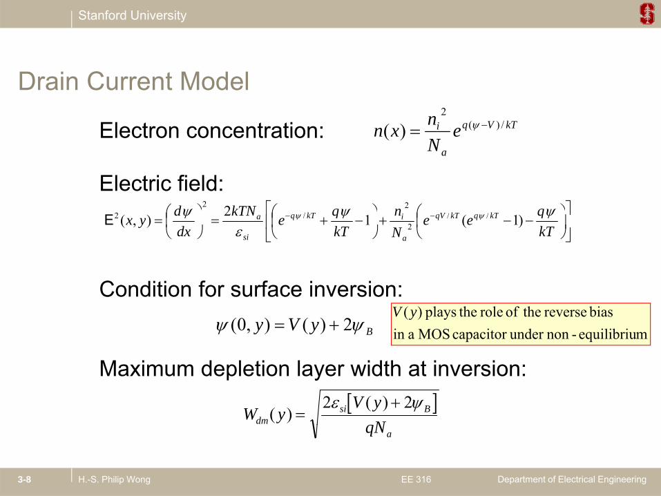
Electron concentration: kTVqi eNnxn /)(
2
)(
Drain Current Model
Electric field:
qnqkTNd kkk 2 //
2/
2
aN
C diti f f i i
kTqee
Nn
kTqekTN
dxdyx kTqkTqV
a
ikTq
si
a
)1(12),( //2
/2E
Condition for surface inversion:
ByVy 2)(),0( mequilibriu-nonunder capacitor MOS ain bias reverse theof role theplays )(yV
Maximum depletion layer width at inversion: W yV y
Ndmsi B( )
( )
2 2
Department of Electrical EngineeringH.-S. Philip Wong EE 3163-8
qNa

Stanford University
Current Density Equationdrift diffusion
dydnqDnEqJ nnn
Dq
kTeNnn
y
nnkT
Vq
A
i
;)(2
dydV
dydn
kTq
dydn
Current density equation (both drift and diffusion):
J x y q n x ydV y
( ) ( )( )
Quasi-
Department of Electrical EngineeringH.-S. Philip Wong EE 3163-9
J x y q n x ydyn n( , ) ( , ) Fermi level

Stanford University
Gradual Channel ApproximationAssumes that vertical field (Ex) is stronger than lateral field (Ey) in the channel region, thus 2-D Poisson’s equation can be solved in terms of 1 D vertical slicesterms of 1-D vertical slices.
Current density equation (both drift and diffusion):dV y( ) Quasi-
Integrate in x- and z-directions,
J x y q n x ydV y
dyn n( , ) ( , )( )
dV dV
Fermi level
where is the inversion charge per unit area.
I y W dVdy
Q y W dVdy
Q Vds eff i eff i( ) ( ) ( )
Q y q n x y dxi
xi( ) ( , ) 0Current continuity requires Ids independent of y, integration with respect to y from 0 to L yields
I W Q V dVVds
( )
Department of Electrical EngineeringH.-S. Philip Wong EE 3163-10
I WL
Q V dVds eff ids ( )
0

Stanford University
Pao-Sah’s Double Integral H. C. Pao and C. T. Sah, “Effects of diffusion current on characteristics of metal-oxide (insulator)-semiconductor transistors,” Solid-State El t l 9 10 927 937 O t 1966
Change variable from (x,y) to (,V),
Vni q V kT( ) ( ) ( )/
2
gElectron., vol. 9, no. 10, pp. 927–937, Oct. 1966.
n x y n VN
ei
a
q V kT( , ) ( , ) ( )/
s
B
B
s
dV
eNnqdddxVnqVQ
kTVqai
i
)()/(),()(
/)(2
E
Substituting into the current expression,
Bs Vd ),(E
ds sV kTVqai dVdeNnWqI
/)(2 )/(
How do you get this
approximation?
(see Lecture Notes p. 2-12 and 2-22
and makewhere (V) is solved by the gate voltage eq for a
B
effds dVdVL
qI0 ),(
E
and make approximations)
where s(V) is solved by the gate voltage eq. for a vertical slice of the MOSFET:
V VQC
VkTN
CqkT
nN
eg fb ss
fb ssi a s i q V kTs
2 2
2
1 2
( ) /
/
Department of Electrical EngineeringH.-S. Philip Wong EE 3163-11
C C kT Nox ox a

Stanford University
Example of ψs vs VG Relationship
Department of Electrical EngineeringH.-S. Philip Wong EE 3163-12
R. van Langevelde, F.M. Klaassen / Solid-State Electronics 44 (2000) 409 - 418

Stanford University
Charge Sheet Approximation
Assumes that all the inversion charges are located at the silicon surface like a sheet of charge and that there is no
t ti l d th i i l
g
potential drop across the inversion layer.
After the onset of inversion, the surface potential is pinned at = 2 + V(y)s = 2B + V(y).
Depletion charge: )2(2 max VqNWqNQ Basidad
Total charge:
Inv. charge:
Q C V V C V V Vs ox g fb s ox g fb B ( ) ( ) 2
Q Q Q C V V V qN Vi s d ox g fb B si a B ( ) ( )2 2 2
W VSubstituting in and integrate:
I C WL
V V V VqN
CVds eff ox g fb B
dsds
si aB ds B
2
22 2
32 23 2 3 2( ) ( )/ /
I WL
Q V dVds eff i
Vds ( )0
Department of Electrical EngineeringH.-S. Philip Wong EE 3163-13
L Cff g fox
2 3J.R. Brews, “A charge-sheet model of the MOSFET,” Solid-State Electronics, Volume 21, Issue 2, February 1978, Pages 345-355

Stanford University
Linear Region I-V CharacteristicsFor Vds << Vg ,
I C WL
V VqN
CV C W
LV V Vds eff ox g fb B
si a Bds eff ox g t ds
2
4( )
g
1E+0 0 8
where is the MOSFET threshold voltage. V VqN
Ct fb Bsi a B
ox 2
4
L C Lox
1E-2
1E+0
0.6
0.8
y sc
ale)
y sc
ale)
65 nm technology
1E-6
1E-4
0.4
g(
) (a
rbitr
ary
ar
(a
rbitr
ary
I ds
I ds
0 0 5 1 1 5 2 2 5 31E-10
1E-8
0
0.2Log
Line
Department of Electrical EngineeringH.-S. Philip Wong EE 3163-14
0 0.5 1 1.5 2 2.5 3Gate Voltage, (V)
VonVt
VgP. Bai et al., “A 65nm Logic Technology Featuring 35nm Gate Lengths, Enhanced Channel 8 Cu Interconnect Layers, Low-k ILD and 0.57 μm2 SRAM Cell,” IEDM, p. 657 (2004).

Stanford University
Experimental Determination of the Threshold Voltage
Linear e trapolation (LE) at the ma im m G point Linear extrapolation (LE) at the maximum Gm point
Constant current (CC) method Often used in industry
Transconductance change (TC) method Used for modeling of
devices
Department of Electrical EngineeringH.-S. Philip Wong EE 3163-15
D.K. Schroeder Semiconductor material and device characterization, 2nd ed, Wiley, New York (1998).

Stanford University
Example Id (and Gm) vs VGS curves
Department of Electrical EngineeringH.-S. Philip Wong EE 3163-16
R. van Langevelde, F.M. Klaassen / Solid-State Electronics 44 (2000) 409 - 418

Stanford University
Example log(Id) vs VGS curves
Department of Electrical EngineeringH.-S. Philip Wong EE 3163-17
R. van Langevelde, F.M. Klaassen / Solid-State Electronics 44 (2000) 409 - 418

Stanford University
Threshold Voltage Extraction Method Illustrationg
Department of Electrical EngineeringH.-S. Philip Wong EE 3163-18
H.S. Wong, M.H. White, T.J. Krutsick and R.V. Booth, Modeling of transconductance degradation and extraction of threshold voltage in thin oxide MOSFET's. Solid State Electron 30 (1987), p. 953.

Stanford University
2 2Example ∂Id / ∂VGS and ∂2Id / ∂VGS 2 vs VGS curves
Department of Electrical EngineeringH.-S. Philip Wong EE 3163-19
R. van Langevelde, F.M. Klaassen / Solid-State Electronics 44 (2000) 409 - 418

Stanford University
Saturation Region I-V Characteristics
Keeping the 2nd order terms in Vds: I C WL
V V V mVds eff ox g t ds ds
( )2
2
I C WL
V V V VqN
CVds eff ox g fb B
dsds
si a
oxB ds B
2
22 2
32 23 2 3 2( ) ( )/ /
where is the body-effect coefficient mqN
CCC
tW
si a B
ox
dm
ox
ox
dm
14
1 1 3 /
Vg4
(Vdsat, Idsat)
W V V( )2 Non-physical part f th I ti
ain
Cur
rent Vg3
when V V (V V )/m
I I C WL
V Vmds dsat eff ox
g t
( )
2of the Ids equation for Vds > Vdsat
Dra
Vg1
Vg2Vds = Vdsat = (Vg Vt)/m
Department of Electrical EngineeringH.-S. Philip Wong EE 3163-21
Drain VoltageTypically, m 1.2

Stanford University
Pinch-off ConditionFrom inversion charge density point of view,
Q V C V V mVi ox g t( ) ( )
while I WL
Q V dVds eff i
Vds ( )0
At V V (V V )/Q Vi( )
At Vds = Vdsat = (Vg Vt)/m,Qi = 0 and Ids = max.
Qi( )
C V Vox g t( )Integrated area under
Ids
g Integrated area under the curve (shaded area)
Vd0 VVd t
Department of Electrical EngineeringH.-S. Philip Wong EE 3163-22
Vds0 VSource Drain
Vdsat
V Vm
g t
Stanford University
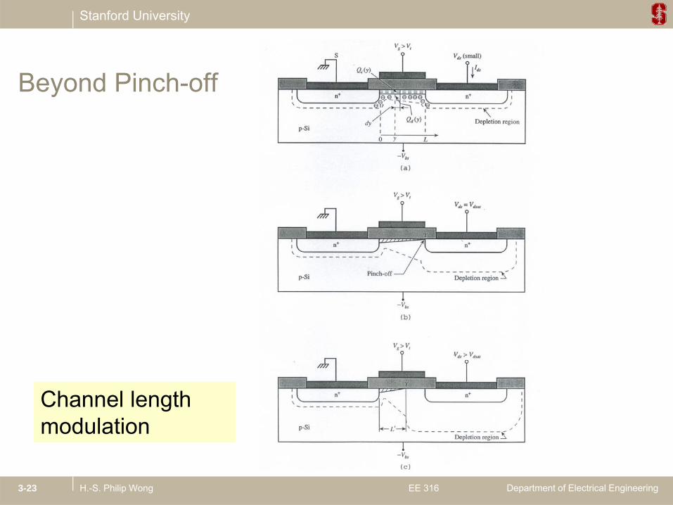
Beyond Pinch-off
Channel length modulation
Department of Electrical EngineeringH.-S. Philip Wong EE 3163-23
modulation

Stanford University
Saturation Characteristics – Experimental Example
65 nm technology
CML DIBL
Slope due to:
C Channel length modulation (CLM)
Drain induced barrier lowering (DIBL) – to be di d l tdiscussed later
Department of Electrical EngineeringH.-S. Philip Wong EE 3163-24
P. Bai et al., “A 65nm Logic Technology Featuring 35nm Gate Lengths, Enhanced Channel 8 Cu Interconnect Layers, Low-k ILD and 0.57 μm2 SRAM Cell,” IEDM, p. 657 (2004).

Stanford University
Subthreshold RegiondydnqDnEqJ nnn
S i
VV V
mdsg t
Vds
1E-2
1E-1
1E+0
ary
units
)
Low DrainBias
Saturationregion
Sub-thresholdregion 1E-5
1E-4
1E-3
Curr
ent (
arbi
tra DiffusionComponent
Linearregion
Vt Vg 0 0.5 1 1.5 21E-8
1E-7
1E-6D
rain
DriftComponent y
s
Gate Voltage (V)
Department of Electrical EngineeringH.-S. Philip Wong EE 3163-25

Stanford University
Subthreshold Currents2/1
/)(2
2
2
kTVq
a
isasissis
seNn
kTqkTNQ E
P i i 1 t t Q 2 d t QPower series expansion: 1st term Qd, 2nd term Qi,
Q qN kTq
nN
eisi a
s
i
a
q V kTs
2
2( )/
I W Q V dVVds
( ) qs a
I WL
qN kTq
nN
e eds effsi a i q kT qV kTs ds
21
2 2/ /
usingforSolving
IL
Q V dVds eff i ( )0
L q Ns a 2
I CWL
mkTq
e eds eff oxq V V mkT qV kTg t ds
( ) ( )/ /1 1
2
or,
2/12
using for Solving
kTq
CkTN
VV s
ox
asisfbg
s
L q
d I mkT kT C
(log )1
Inverse subthreshold slope: 10ln /60/)10ln( 1 decmVqkT
Department of Electrical EngineeringH.-S. Philip Wong EE 3163-26
S d IdV
mkTq
kTq
CC
ds
g
dm
ox
(log ) . .2 3 2 3 1 300Kat
/60/)10ln( decmVqkT

Stanford University
Subthreshold log(ID)ISubthreshold
Slope (S)MOSFET
Ion
1 decade
VS Ioff
)10ln(kTC1ΨVIlogdS dmSG1
D
0 VGVT VDD
)10ln(qC
1IlogΨdV
gS ox
dm
D
S
S
G
G
D
60 V/d i MOSFET d tG t t h l t ti l
Department of Electrical EngineeringH.-S. Philip Wong EE 3163-27
60 mV/dec in MOSFETs due to Fermi-Dirac distribution
Gate to channel potential coupling: >1 in MOSFETs

Stanford University
Q ti ?Questions?
Department of Electrical EngineeringH.-S. Philip Wong EE 3163-28

Stanford University
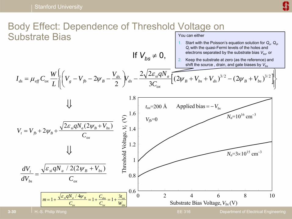
Body Effect: Dependence of Threshold Voltage on y p gSubstrate Bias
You can either
1 Start with the Poisson’s1. Start with the Poisson’s equation solution for Qs, Qd, Qi with the quasi-Fermi levels of the holes and electrons separated by the substrate bias Vbs, or
2. Keep the substrate at zero (as the reference) and shift the source , drain, and gate biases by Vbs
Department of Electrical EngineeringH.-S. Philip Wong EE 3163-29
Stanford University
Body Effect: Dependence of Threshold Voltage on
If Vbs 0,
y p gSubstrate Bias You can either
1. Start with the Poisson’s equation solution for Qs, Qd, Qi with the quasi-Fermi levels of the holes and electrons separated by the substrate bias Vbs, or
2. Keep the substrate at zero (as the reference) and
I C WL
V V V VqN
CV V Vds eff ox g fb B
dsds
si a
oxB bs ds B bs
2
22 2
32 23 2 3 2( ) ( )/ /
shift the source , drain, and gate biases by Vbs
1.6
1.8
(V)
tox=200 Å
Vfb=0 Na=1016 cm3
qN V2 2 ( )
bsV bias Applied
1.2
1.4ol
d Vo
ltage
, V t
Na=31015 cm3
V VqN V
Ct fb Bsi a B bs
ox
2
2 2
( )
0.8
1
Thre
sho
dVdV
qN VC
t
bs
si a B bs
ox
/ ( )2 2
Department of Electrical EngineeringH.-S. Philip Wong EE 3163-30
0 2 4 6 8 100.6
Substrate Bias Voltage, (V) Vbs m
qNC
CC
tW
si a B
ox
dm
ox
ox
dm
14
1 1 3 /

Stanford University
Body Biasing for Low Powery g
Department of Electrical EngineeringH.-S. Philip Wong EE 3163-31

Stanford University
Application of Body Bias for Controlling VariationsApplication of Body Bias for Controlling Variations
Department of Electrical EngineeringH.-S. Philip Wong EE 3163-32
Stanford University
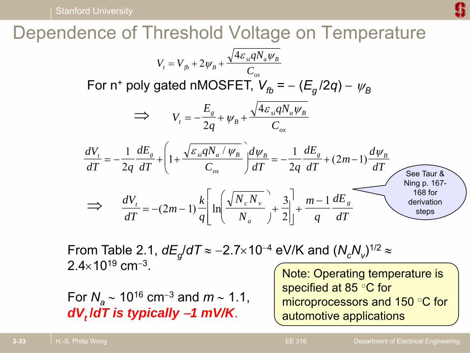
Dependence of Threshold Voltage on Temperature
For n+ poly gated nMOSFET, Vfb = (Eg /2q) B
V VqN
Ct fb Bsi a B
ox 2
4
VEq
qNCt
gB
si a B
ox
24
dV dE qN d dE d 1 1 /
dVdT q
dEdT
qNC
ddT q
dEdT
mddT
t g si a B
ox
B g B
12
11
22 1
/( )
dV k N N m dE
3 1
See Taur & Ning p. 167-
168 for derivation
From Table 2 1 dE /dT 2 7104 eV/K and (N N )1/2
dVdT
mkq
N NN
mq
dEdT
t c v
a
g
( ) ln2 1
32
1 derivation steps
From Table 2.1, dEg/dT 2.710 eV/K and (NcNv) 2.41019 cm3.
For Na 1016 cm3 and m 1.1,
Note: Operating temperature is specified at 85 ○C for microprocessors and 150 ○C for
Department of Electrical EngineeringH.-S. Philip Wong EE 3163-33
a ,dVt /dT is typically 1 mV/K.
microprocessors and 150 C for automotive applications

Stanford University
Carrier Transport and Gate Capacitance
Linear Region:
dstgoxeffds VVVL
WCI )(
W V V( )2
Saturation Region:
I I C WL
V Vmds dsat eff ox
g t
( )
2
Will come back to a more elaborate discussion later in the course about carrier transport.
Let’s first digress briefl abo t the gate capacitance C and the
Department of Electrical EngineeringH.-S. Philip Wong EE 3163-34
Let’s first digress briefly about the gate capacitance Cox and the effective mobility µeff right now (we will return to them later again)

Stanford University
MOSFET Channel Mobility Weighted average
effn
x
x
n x dx
n x dx
i
i
( )
( )0
MOSFET Channel Mobilitywith inversion carrier
density
n x dx ( )0
It was empirically found that when eff is plotted against an effective normal field Eeff, there exists a “universal relationship” independent of the substrate bias dopingrelationship independent of the substrate bias, doping concentration, and gate oxide thickness (Sabnis and Clemens, IEDM 1979).Here
QQ 11EHere
id
sieff QQ
2E
Since and Qi Cox(Vg Vt), Q qN C V Vd si a B ox t fb B 4 2 ( )
ox
tg
ox
Bfbt
tVV
tVV
632
effE
VVV 20
Department of Electrical EngineeringH.-S. Philip Wong EE 3163-35
ox
tg
ox
t
tVV
tV
632.0
effEFor n+ poly gated nMOSFET,

Stanford University
Low field region (low electron density): Limited by
Electron Mobility
electron density): Limited by impurity or Coulomb scattering (screened at high electron densities).
Intermediate field region: Limited by phonon scattering,
High field region (> 1
3/132500 Eeff
High field region (> 1 MV/cm): Limited by surface roughness scattering (less temp dependence)
Department of Electrical EngineeringH.-S. Philip Wong EE 3163-36
temp. dependence).

Stanford University
Temperature Dependence of MOSFET Current
Note: Operating temperature isNote: Operating temperature is specified at 85 ○C for microprocessors and 150 ○C for automotive applications
Department of Electrical EngineeringH.-S. Philip Wong EE 3163-37

Stanford University
Hole Mobility
id
sieff QQ
311
E
In general, pMOSFET mobility does not exhibit “universal” behavior as well as nMOSFET
Department of Electrical EngineeringH.-S. Philip Wong EE 3163-38
“universal” behavior as well as nMOSFET.

Stanford University
Gate to body
C WLC C
WLCg d
1 11
Subthreshold region:
Intrinsic MOSFET Capacitance body capacitance
C Cox d C WLCg ox Linear region:
Saturation region:
What is the gate to source and gate to drain
capacitance in
Gate to channel
Q y C V V yLi ox g t( ) ( ) 1
Saturation region: capacitance in subthreshold?
Wh t i th t
capacitance
Q yLi ox g t( ) ( )
C WLCg ox23
What is the gate to body
capacitance in the linear region?
3
See Taur & Ning p. 131 for derivation
Department of Electrical EngineeringH.-S. Philip Wong EE 3163-39
steps