Pivot-Door Downdraft Cabinet Plans - Incra
7
® www.incra.com Pivot-Door Downdraft Cabinet Plans rev. 09.23.08 ©2008 by Taylor Design Group. All rights reserved. Finished Cabinet Introduction This simple downdraft-style dust collection cabinet is a great way to keep your shop cleaner and keep your router quieter. The simple design can be easily constructed from a wide variety of materials available at home centers and hardware stores. There are no conventional hinges to install, and the all-wood joinery allows a fast, satisfying build. Material Choices: For the cabinet housing, good-quality birch or oak-veneer plywood are recommended, but MDF also works well. The door panel can be an edge-glued hardwood panel or plywood (with edge banding for neatness). MDF has the advantage of being inexpensive, flatter than plywood, and more consistent for thickness. It can also be quite attractive with a few coats of polyurethane finish. Hardware Choices: A remote router switch with a length of cord on the female end is ideal, but a short, heavy (12ga or 14ga.) extension cord can also bring power into the cabinet. The hardware and door catches are widely available at hardware stores and home centers. For the nuts and bolts, many better hardware stores carry stainless steel or chrome-plated hardware to add some style to the project. page 1 Closed Open Exploded View
Transcript of Pivot-Door Downdraft Cabinet Plans - Incra
®
w w w . i n c r a . c o mPivot-Door Downdraft Cabinet Plans
rev. 09.23.08 ©2008 by Taylor Design Group. All rights reserved.
Finished Cabinet
Introduction
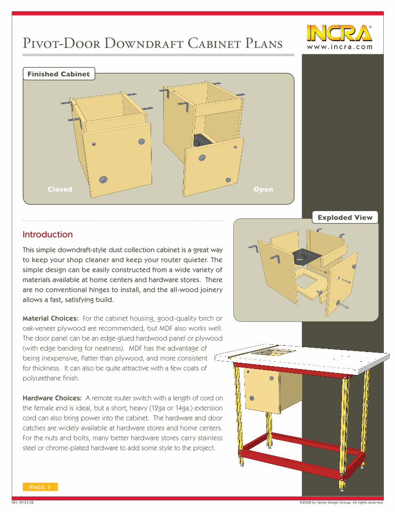
This simple downdraft-style dust collection cabinet is a great way to keep your shop cleaner and keep your router quieter. The simple design can be easily constructed from a wide variety of materials available at home centers and hardware stores. There are no conventional hinges to install, and the all-wood joinery allows a fast, satisfying build.
Material Choices: For the cabinet housing, good-quality birch or oak-veneer plywood are recommended, but MDF also works well. The door panel can be an edge-glued hardwood panel or plywood (with edge banding for neatness). MDF has the advantage of being inexpensive, flatter than plywood, and more consistent for thickness. It can also be quite attractive with a few coats of polyurethane finish.
Hardware Choices: A remote router switch with a length of cord on the female end is ideal, but a short, heavy (12ga or 14ga.) extension cord can also bring power into the cabinet. The hardware and door catches are widely available at hardware stores and home centers. For the nuts and bolts, many better hardware stores carry stainless steel or chrome-plated hardware to add some style to the project.
page 1
Closed Open
Exploded View

®
w w w . i n c r a . c o m
page 2
Materials:
Lumber Cutting List:
Part Qty. T W L Material
Side Panels 2 3/4” 14-1/16” 14-3/4” Veneered plywood or MDF
Back Panel 1 3/4” 10-3/8” 13-3/16” Veneered plywood or MDF
Bottom Panel 1 3/4” 10-3/8” 14” Veneered plywood or MDF
Front Brace 2 3/4” 2-1/4” 10-3/8” * Veneered plywood or MDF
Door Panel 1 3/4” 11-7/8” 13-1/2” Edge-glued hardwood,veneered plywood, or MDF
* Length of Front Braces should perfectly match the width of bottom panel.
3/4” plywood or MDF, roughly 26” x 46”
Dust collection fitting – Rockler #21025 or similar
Remote 15 Amp router switch (optional but recommended)
Rockler #20915 Woodcraft #141938 Bench Dog #04-028
(4) Corner braces - National Hardware #N227-405 2” x 5/8” or similar
Note: Corner brace screws must be no longer than 3/4” when attaching the cabinet to an INCRA stand-alone router table and no longer than 1/2” when installing the cabinet on an INCRA TS router table.
(1) Cabinet door pull or knob
(1) Magnetic or roller cabinet door catch
(1) 5/16”-18 x 2” socket head cap screw
(2) 5/16” fender washers
(1) 5/16”-18 nylon insert lock nut
(1) 1/4”-20 x 1-1/4” (or 1-1/2”)
(1) 1/4”-20 nylon insert locknut
(1) 1/4” flat washer
®
w w w . i n c r a . c o m
page 3
1. Think First
Take a few moments to read the instructions in their entirety. A better understanding of the entire project will allow you
to work more efficiently and accurately during the construction. Here are a few general guidelines:
a. This cabinet is intended to be used with INCRA offset-style router tables and router table stands.
It can also be installed on INCRA TS Router Tables.
b. The design assumes that the router table stand is attached to the router table using the dimensions
specified in the router table stand instructions.
c. A crosscutting sled will allow better control than a miter gauge for squaring up the larger components.
d. Widths of rabbets and dados are approximately 3/4”. The actual width should be matched to the
exact thickness of your material to produce the best fitting joints.
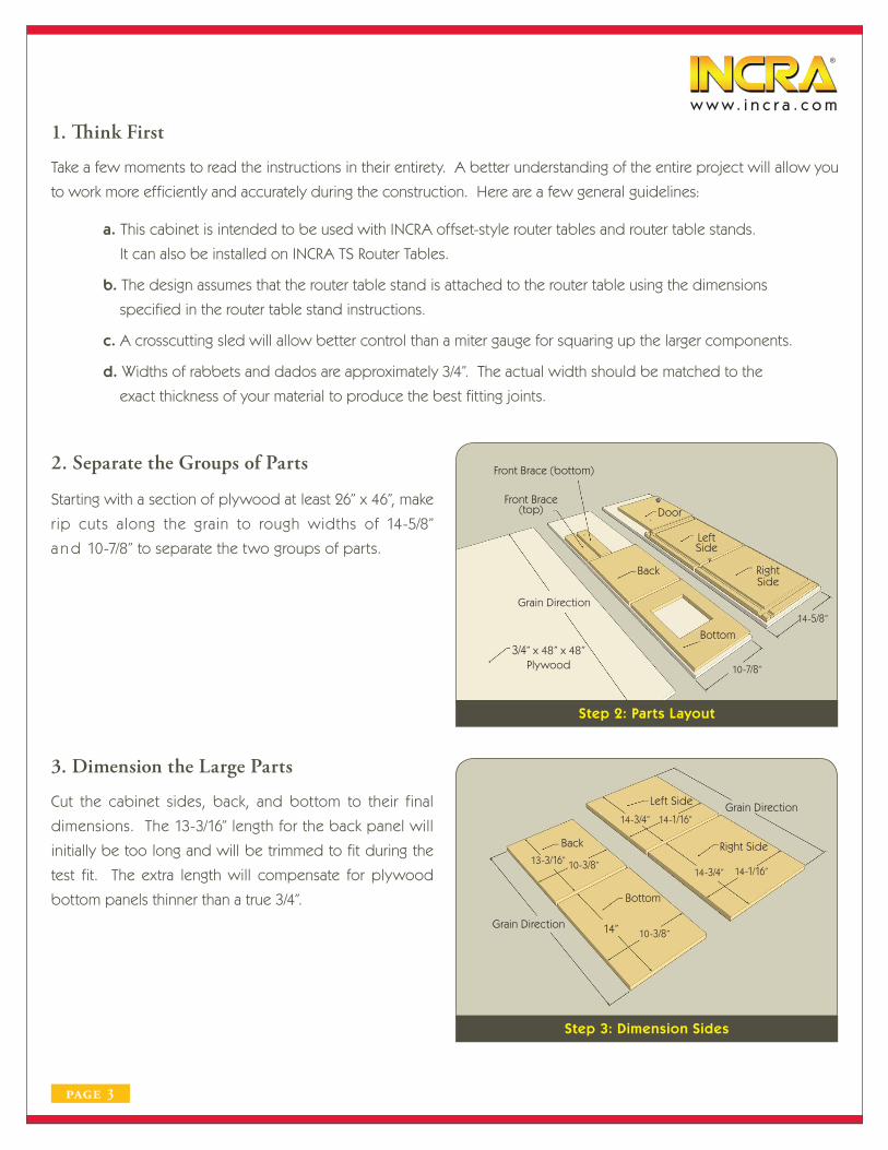
2. Separate the Groups of Parts
Starting with a section of plywood at least 26” x 46”, make
rip cuts along the grain to rough widths of 14-5/8”
a n d 10-7/8” to separate the two groups of parts.
Step 2: Parts Layout
3. Dimension the Large Parts
Cut the cabinet sides, back, and bottom to their final
dimensions. The 13-3/16” length for the back panel will
initially be too long and will be trimmed to fit during the
test fit. The extra length will compensate for plywood
bottom panels thinner than a true 3/4”.
Step 3: Dimension Sides
Grain Direction
10-7/8”
3/4” x 48” x 48”Plywood
Front Brace(top)
Front Brace (bottom)
Back
Door
LeftSide
Bottom
RightSide
14-5/8”
Grain Direction
Back
13-3/16” 10-3/8”
Bottom
14” 10-3/8”
Grain DirectionLeft Side
Right Side
14-1/16”
14-3/4” 14-1/16”
14-3/4”
®
w w w . i n c r a . c o m
page 4
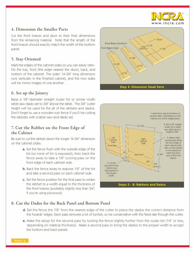
4. Dimension the Smaller PartsCut the front braces and door to their final dimensions from the remaining material. Note that the length of the front braces should exactly match the width of the bottom panel.
Step 4: Dimension Small Parts
5. Stay OrientedMark the edges of the cabinet sides so you can easily iden-tify the top, front (the edge nearest the door), back, and bottom of the cabinet. The sides’ 14-3/4” long dimension runs vertically in the finished cabinet, and the two sides will be mirror images of one another.
6. Set up the JoineryRaise a 1/2”-diameter straight router bit or similar width table saw dado set to 3/8” above the table. The 3/8” cutter height will be used for the all of the rabbets and dados. Don’t forget to use a wooden sub fence if you’ll be cutting the rabbets with a table saw and dado set.
7. Cut the Rabbet on the Front Edge of the CabinetBe sure to cut the rabbet down the longer 14-3/4” dimensionon the cabinet sides.
a. Set the fence flush with the outside edge of the bit (so none of bit is exposed), then back the fence away to take a 1/8” scoring pass on the front edge of each cabinet side.
b. Back the fence away to expose 1/2” of the bit and take a second pass on each cabinet side.
c. Set the fence position for the final pass to widen the rabbet to a width equal to the thickness of the front braces (probably slightly less than 3/4”, if you’re using plywood).
8. Cut the Dados for the Back Panel and Bottom Panel
d. Set the fence the 7/8” from the nearest edge of the cutter to place the dados the correct distance from the boards’ edges. Each pass removes a lot of lumber, so be conservative with the feed rate through the cutter.
e. Make the setup for the second pass by locking the fence slightly further from the router bit (1/4” or less, depending on material thickness). Make a second pass to bring the dados to the proper width to accept the bottom and back panels.
Steps 5 - 8: Rabbets and Dados
Door
13-1/2”Front Brace (top)
Front Brace (bottom)
10-3/8”
10-3/8”
2-1/4”
2-1/4”
Grain Direction 11-7/8”
1. Mark front, rear and bottom ofcabinet sides. Note tahat you’ll bemaking two mirror-imaged parts.
2. Set a 1/2” straightrouter bit or tablesaw dado set to a
height of 3/8”.
3. Make a lightscoring pass alongthe front edge of
each cabinet side,then cut the rabbet
in two passes tomatch the thick-ness of the front
braces.
14-3/4”
3/4”(approx.)
3/8”
RightCabinet
Side
Rear Front
14-1/16”
7/8”
3/4”3/4”
4. Cut thegrooves for the
bottom andback panels to
the properwidth.
LeftCabinet
Side
Front Rear

®
w w w . i n c r a . c o m
page 5
9. Cut Access for the Power Cord
Raise the router bit to just over 3/4” so it cuts through the
entire thickness of the plywood. Set the fence about 4”
from the bit. Slowly feed the cabinet side into the bit to
cut a small notch for the power cord.
Step 9: Power Cord Access
10. Prepare the Bottom for Dust Collection
Mark the bottom panel so you can identify which edge
faces the front of the cabinet. Cut the opening in the
bottom panel to match the dust collection fitting you
intend to use (use a 4” fitting; a 2-1/2” hose won’t move
enough air volume). Dimensions shown are for Rockler’s
#21025 fitting. A fitting offset toward the sides of the
cabinet will provide slightly better performance than one
that’s mounted directly beneath the router.
Install the fitting with screws or construction adhesive.
If a woodworking dust collection fitting is not available
locally, a PVC “closet flange” with an outside diameter that
accepts 4” dust collection hose can be purchased in the
plumbing aisles of nearly any home center.
11. Hinge the Door
Mark the top and left end of the lower front brace. Drill
the holes for the door pivot in the lower front brace and
door at the appropriate locations. A 21/64” drill bit is
ideal, but an 11/32” bit will also work.
Step 10: Dust Collection
Step 11: Hinge Drilling
Rockler Dust Port#21025 (8” x 8”)
6-9/16”
1-1/2”
2-7/8”
10-3/8”
14”
6-1/2”
Rear Front
Front Brace(bottom)
Approx. 4”
Left CabinetSide
Rear Front
Left Edge
Top Edge
Bottom FrontBrace
3/4”
1-3/4”21/64”
Door Panel
2-1/2”21/64”
3-5/8”

®
w w w . i n c r a . c o m
page 6
12. Bring the Parts Together
Test-fit the cabinet assembly and gather the necessary clamps and materials for the glue-up.
Trim the length of the back panel so it’s flush at the top of the cabinet while resting against the bottom panel.
Step 12: Dry Assembly
13. Assemble the Cabinet
Begin the glue up with the cabinet on its side. Position the bottom, back, and lower front brace in their respective rabbets and grooves. Be sure the bottom panel and the lower front brace are properly oriented. Get the remaining cabinet side started, add the upper front brace, and check that the cabinet is square after all the parts are seated.
Weight can be added to the top with the cabinet on its side while the glue dries, or the cabinet can be turned bottom-up and the parts clamped into position.
If you used plywood for the door, now’s a great time to apply edge banding to cover the plies. Iron-on banding iswidely available and easy to apply.
Step 13: Glue Up
Step 14: Install Knob
14. Install the Door Handle
Install the knob of choice toward the upper-right corner of the door.
Note: Knob hardware left proud of the surface on the back of the door panel will prevent the door from pivoting. Your options include using a flat head screw, counter boring (leaving a flat-bottom hole) to recess a round-head or pan-head screw below the surface, or making a wooden handle and gluing it in place.
Also drill a 1/4” hole in the upper left corner of the door at the dimensions shown to accept the bolt for the door’s down-stop.
Trim length of back panelso it rests on the bottom
panel and is flush with the top of the cabinet
Pivot hole on left side
Front bracesflush with front
of sides
All topedges should
be flush
Bottom panelflush with rear
of cabinet
Begin the glue-up withthe cabinet on its side
1. Glue the bottom andback into their grooves
2. Glue the lower frontbrace to the bottom andsides with the pivot bolthole oriented correctly
3. Start the remainingcabinet side in the
grooves
4. Install the remainingfront brace
5. Seat all of the parts and check for square. Weight can be added
on top, or the cabinet can be tipped bottom-up
and clamped
Drill 1/4” holefor door stop
bolt
1-9/16”
2”
Pivot Bolt Hole
Attached a knob or shop-made wooden handle in the upper-right part of the door
panel
2”
3” Rear of Door
Countersink or counter-boreon the back of the door
so the door knob hardwareis recessed

®
w w w . i n c r a . c o m
page 7
15. Attach the Door
Slip the 5/16”-18 pivot bolt with a large washer through the holes in the door and lower front brace from the outside of the cabinet, and install the other washer and nut inside. Use a nylon-insert lock nut and tighten the nut to a point where the door can pivot smoothly but without excess play.
Install the 1/4”-20 door stop bolt, nut and washer. Note that there is no washer on the inside of the door. Tighten the door stop bolt fully.
Step 15: Install Door
16. Install the Catch Mount the catch components on the underside of the cabinet near the right side in the corner opposite the pivot. Inexpensive roller catches or strong magnetic catches for cabinet doors are widely available. Clamp the door in the closed position to make it easier to mark the locations of the catch components. Typically, the magnet or roller catch should be attached to the door and the striker screwed to the cabinet’s bottom panel.
Step 16A: Install Door Catch
17. Attach the Cabinet to the Router Table
Steel L-brackets or corner braces are the easiest way to attach the cabinet to the table.
Turn the router table upside down and attach two corner braces to each side of the cabinet using the router table’s bottom surface as a reference.
Roughly center the top of the cabinet over the router table opening (clamping the door open helps) and lead the female end of the extension cord or remote switch cord into the cabinet through the notch in the cabinet side.
Drill pilot holes for the corner brace screws in the laminate on the underside of the router table and attach the cabinet to the router table.
Step 17: Attach to Router Table
Caution: Double check the length of the screws to ensure that screws driven into the bottom of the router table won’t contact the aluminum miter channel installed in the top of the table. The screws must be 3/4” or shorter for INCRA stand-alone router tables and 1/2” or less for INCRA TS router tables.
Step 16B: Install Door Catch
Install the 1/4”-20 door stop bolt, lock nut and washer (note that there
is no washer on the inner side of the door).
Tighten fully.
Install the door with the 5/16”bolt, washers and nut.
Use a nylon-insert lock nutand tighten until door pivots
smoothly and without excess play at the pivot
Clamp the door inthe closed position
1. Mark the locationsfor the catch and
striker
2. Unclamp and openthe door to more
easily install the catchcomponents
Roller catch ormagnetic catch
housing attaches to door
Catch striker or strike plate mounts on cabinet bottom
Attach two corner braces to each
side of thecabinet
Drill pilot hole inthe laminate and
screw the cabinet to the router table