Pitts Model 12 15e ARF - Horizon Hobby · Pitts Model 12 15e ARF ... We would like to personally...
36
Specifications Wingspan: 40 in (1015mm) Length: 39 in (990mm) Wing Area: 555 sq in (35.8 sq dm) Weight w/ Battery: 48–50 oz (1360–1420 g) Weight w/o Battery: 43–45 oz (1220–1275 g) Pitts Model 12 15e ARF Assembly Manual
Transcript of Pitts Model 12 15e ARF - Horizon Hobby · Pitts Model 12 15e ARF ... We would like to personally...

SpecificationsWingspan: 40 in (1015mm)Length: 39 in (990mm)Wing Area: 555 sq in (35.8 sq dm)Weight w/ Battery: 48–50 oz (1360–1420 g)Weight w/o Battery: 43–45 oz (1220–1275 g)
Pitts Model 12 15e ARFAssembly Manual

2 E-flite Pitts Model 12 15e ARF Assembly Manual
IntroductionThe E-flite® Pitts Model 12 15e ARF is a 3D-capable, sport replica of one of aviation’s hottest aerobatic machines. Designed by veteran world class competitor, Quique Somenzini, it will give intermediate to expert pilots a thrilling scale aerobatic experience unlike any other. The large wing area and light wing loading of its biplane design offers very forgiving flight characteristics while keeping roll response crisp and precise. E-flite’s Power 15 and Power 25 brushless outrunner motors are excellent power choices, depending on your skill level. Sport aerobatics or stick-bending 3D, the Pitts Model 12 15e will do whatever you ask and will look good doing it.
Scale Outline and HistoryDesigned by Quique Somenzini, this Pitts Model 12's outline is accurate with the following exceptions. The vertical fin and rudder area has been increased slightly to deliver an improved feel and handling qualities during aggressive 3D maneuvering. The horizontal stab has been raised slightly for the same reason.
The airplane modeled is owned by Keyes Kaitis of Joliet, Illinois. You will see the full-size aircraft on the top of the box. We have deviated from the scale paint scheme in a few minor areas. First, our cowling front ring, landing gear, and wheel pants are painted silver. The real aircraft is polished aluminum in these areas. This is something we cannot currently duplicate. Next we have changed the trim scheme on the bottom of the wings. This was done to ensure there was a contrast from the top to the bottom wing to aid during 3D flight for our customers. Other than these deviations, we have tried to maintain the lines of the Pitts Model 12 as it is currently flown.
We would like to personally thank both Keyes Kaitis and Mark Streitz for their help on this project. Without the efforts of these two men, we would not have been able to bring you this replica of the Pitts Model 12.
Table of ContentsSpecifications ...................................................................... 1Introduction ......................................................................... 2Scale Outline and History .................................................... 2Using the Manual ................................................................ 3Contents of Kit/Parts Layout ................................................. 3Required Radio Equipment ................................................... 3Important Information About Motor Selection ........................ 4Lightweight 3D Outrunner Setup ........................................... 4Sport Outrunner Setup ......................................................... 4Optional Accessories ........................................................... 4Required Tools and Adhesives .............................................. 4Notes Regarding Servos and ESC ........................................ 5Note on Lithium Polymer Batteries ........................................ 5Warning ............................................................................. 5Warranty Period ................................................................. 5Limited Warranty ................................................................ 5Damage Limits .................................................................... 6Safety Precautions ............................................................... 6Questions, Assistance, and Repairs ...................................... 6Inspection or Repairs ........................................................... 6Warranty Inspection and Repairs ......................................... 6Non-Warranty Repairs ........................................................ 7Safety, Precautions, and Warnings ....................................... 7Hinging the Control Surfaces ............................................... 8Wing Installation ............................................................... 11Stabilizer Installation ......................................................... 14Rudder Installation ............................................................. 16Landing Gear Installation ................................................... 18Radio Installation ............................................................... 21Motor Installation .............................................................. 27Final Detail Installation ....................................................... 30Control Throws .................................................................. 32Center of Gravity .............................................................. 33Range Test Your Radio ....................................................... 33Preflight ............................................................................ 34Flying Your Pitts Model 12 15e ARF ................................... 342007 Official AMA National Model Aircraft Safety Code ... 35

3E-flite Pitts Model 12 15e ARF Assembly Manual
Using the ManualThis manual is divided into sections to help make assembly easier to understand, and to provide breaks between each major section. In addition, check boxes have been placed next to each step to keep track of each step completed. Steps with a single circle () are performed once, while steps with two circles ( ) indicate that the step will require repeating, such as for a right or left wing panel, two servos, etc.
Remember to take your time and follow the directions.
Contents of Kit/Parts LayoutLarge Replacement Parts
EFL2551 Wing Set w/aileronsEFL2552 Fuselage w/rudderEFL2553 Tail setEFL2554 CowlingEFL2555 Landing gearEFL2556 Wheel pantsEFL2557 Pushrod setEFL2558 Canopy
Required Radio Equipment
You will need a minimum 6-channel transmitter (for proper mixing and dual rate capabilities), crystals, micro receiver, and four micro servos. You can choose to purchase a complete radio system that includes all of these items or, if you are using an existing transmitter, just purchase the other required equipment separately. We recommend the crystal-free, interference-free Spektrum™ DX7 2.4GHz DSM® 7-channel system. If using your own transmitter, we recommend the JR SPORT™ MC35 Micro servos.
If you own the Spektrum DX7 radio, just add the AR7000 DSM2™ 7-channel receiver and four of our JR SPORT MC35 Micro servos.Complete Radio System
SPM2710 DX7 DSM 7CH systemOr Purchase Separately
JRPR720UL UltraLite 7-Channel ScanSelect FM Receiver (72MHz)
OrSPMAR6200 AR6200 DSM2 6-Channel Receiver Ultralite
(for DX7 only)Or
SPM6070 AR7000 DSM2 7CH Rx (for DX7 only)And
JSP20030 MC35 Micro Servo (4)EFLREX6L 6-inch lightweight extension (2)EFLREX9L 9-inch lightweight extension (2)

4 E-flite Pitts Model 12 15e ARF Assembly Manual
Important Information About Motor Selection
We recommend the E-flite® Power 15 Brushless Outrunner, 950Kv (EFLM4015A) to provide you with lightweight 3D performance, or the Power 25 Brushless Outrunner, 870Kv (EFLM4025A) for sport performance.
Lightweight 3D Outrunner SetupEFLM4015A Power 15 BL Outrunner, 950KvEFLA1060 60-Amp Pro Switch-Mode
BEC Brushless ESCTHP20704SX 2070mAh 4-Cell 14.8V Li-PoAPC11080E 11 x 8 Electric PropEFLAEC303 EC3 Device & Battery Connector,
Male/FemaleEFLC3005 Celectra™ 1- to 3-Cell Li-Po Charger
This is a high-power performance setup for strong 3D flights.
Sport Outrunner SetupEFLM4025A Power 25 BL Outrunner, 870KvEFLA1060 60-Amp Pro Switch-Mode
BEC Brushless ESCTHP42003S2PPL 4200mAh 3-Cell 11.1V Li-PoAPC12080E 12 x 8 Electric PropEFLAEC303 EC3 Device & Battery Connector,
Male/FemaleEFLC3005 Celectra 1- to 3-Cell Li-Po Charger
This is a high-power performance setup for sport flights.
Optional AccessoriesEFLA110 Power Meter
Required Tools and AdhesivesTools & Equipment
EFLA250 Park Flyer Tool Assortment, 5-pieceOr Purchase Separately
EFLA257 Screwdriver, #0 Phillips (or included with EFLA250)
EFLA251 Hex Wrench: 3/32-inch (or included with EFLA250)
DrillDrill bit: 1/16-inch (1.5mm)Felt-tipped penThreadlockT-pinsThin CAMedium CAPaper towelsHobby knife (#11 blade)6-minute epoxyPliersRulerSquareSandpaper5/64-inch (2mm) drill bit30-minute epoxyPhillips screwdriver: #0, #1Masking tapeCanopy glueRotary tool3mm ball driverPin drillSide cutters

5E-flite Pitts Model 12 15e ARF Assembly Manual
Notes Regarding Servos and ESC
WARNING: Use of servos other than those we recommend may overload the BEC of the recommended Electronic Speed Control (ESC). We suggest the use of only the servos we recommend when utilizing the recommended ESC’s BEC, or the use of a separate BEC (like the UBEC) or receiver battery pack when using other servos.
Note on Lithium Polymer BatteriesLithium Polymer batteries are significantly more volatile than alkaline or Ni-Cd/Ni-MH batteries used in RC applications. All manufacturer’s instructions and warnings must be followed closely. Mishandling of Li-Po batteries can result in fire. Always follow the manufacturer’s instructions when disposing of Lithium Polymer batteries.
WarningAn RC aircraft is not a toy! If misused, it can cause serious bodily harm and damage to property. Fly only in open areas, preferably at AMA (Academy of Model Aeronautics) approved flying sites, following all instructions included with your radio.
Keep loose items that can get entangled in the propeller away from the prop, including loose clothing, or other objects such as pencils and screwdrivers. Especially keep your hands away from the propeller.
Warranty PeriodHorizon Hobby, Inc., (Horizon) warranties that the Products purchased (the “Product”) will be free from defects in materials and workmanship at the date of purchase by the Purchaser.
Limited Warranty(a) This warranty is limited to the original Purchaser ("Purchaser") and is not transferable. REPAIR OR REPLACEMENT AS PROVIDED UNDER THIS WARRANTY IS THE EXCLUSIVE REMEDY OF THE PURCHASER. This warranty covers only those Products purchased from an authorized Horizon dealer. Third party transactions are not covered by this warranty. Proof of purchase is required for warranty claims. Further, Horizon reserves the right to change or modify this warranty without notice and disclaims all other warranties, express or implied.
(b) Limitations- HORIZON MAKES NO WARRANTY OR REPRESENTATION, EXPRESS OR IMPLIED, ABOUT NON-INFRINGEMENT, MERCHANTABILITY OR FITNESS FOR A PARTICULAR PURPOSE OF THE PRODUCT. THE PURCHASER ACKNOWLEDGES THAT THEY ALONE HAVE DETERMINED THAT THE PRODUCT WILL SUITABLY MEET THE REQUIREMENTS OF THE PURCHASER’S INTENDED USE.
(c) Purchaser Remedy- Horizon's sole obligation hereunder shall be that Horizon will, at its option, (i) repair or (ii) replace, any Product determined by Horizon to be defective. In the event of a defect, these are the Purchaser's exclusive remedies. Horizon reserves the right to inspect any and all equipment involved in a warranty claim. Repair or replacement decisions are at the sole discretion of Horizon. This warranty does not cover cosmetic damage or damage due to acts of God, accident, misuse, abuse, negligence, commercial use, or modification of or to any part of the Product. This warranty does not cover damage due to improper installation, operation, maintenance, or attempted repair by anyone other than Horizon. Return of any goods by Purchaser must be approved in writing by Horizon before shipment.

6 E-flite Pitts Model 12 15e ARF Assembly Manual
Damage LimitsHORIZON SHALL NOT BE LIABLE FOR SPECIAL, INDIRECT OR CONSEQUENTIAL DAMAGES, LOSS OF PROFITS OR PRODUCTION OR COMMERCIAL LOSS IN ANY WAY CONNECTED WITH THE PRODUCT, WHETHER SUCH CLAIM IS BASED IN CONTRACT, WARRANTY, NEGLIGENCE, OR STRICT LIABILITY. Further, in no event shall the liability of Horizon exceed the individual price of the Product on which liability is asserted. As Horizon has no control over use, setup, final assembly, modification or misuse, no liability shall be assumed nor accepted for any resulting damage or injury. By the act of use, setup or assembly, the user accepts all resulting liability.
If you as the Purchaser or user are not prepared to accept the liability associated with the use of this Product, you are advised to return this Product immediately in new and unused condition to the place of purchase.
Law: These Terms are governed by Illinois law (without regard to conflict of law principals).
Safety PrecautionsThis is a sophisticated hobby Product and not a toy. It must be operated with caution and common sense and requires some basic mechanical ability. Failure to operate this Product in a safe and responsible manner could result in injury or damage to the Product or other property. This Product is not intended for use by children without direct adult supervision. The Product manual contains instructions for safety, operation and maintenance. It is essential to read and follow all the instructions and warnings in the manual, prior to assembly, setup or use, in order to operate correctly and avoid damage or injury.
Questions, Assistance, and RepairsYour local hobby store and/or place of purchase cannot provide warranty support or repair. Once assembly, setup or use of the Product has been started, you must contact Horizon directly. This will enable Horizon to better answer your questions and service you in the event that you may need any assistance. For questions or assistance, please direct your email to [email protected], or call 877.504.0233 toll free to speak to a service technician.
Inspection or RepairsIf this Product needs to be inspected or repaired, please call for a Return Merchandise Authorization (RMA). Pack the Product securely using a shipping carton. Please note that original boxes may be included, but are not designed to withstand the rigors of shipping without additional protection. Ship via a carrier that provides tracking and insurance for lost or damaged parcels, as Horizon is not responsible for merchandise until it arrives and is accepted at our facility. A Service Repair Request is available at www.horizonhobby.com on the “Support” tab. If you do not have internet access, please include a letter with your complete name, street address, email address and phone number where you can be reached during business days, your RMA number, a list of the included items, method of payment for any non-warranty expenses and a brief summary of the problem. Your original sales receipt must also be included for warranty consideration. Be sure your name, address, and RMA number are clearly written on the outside of the shipping carton.
Warranty Inspection and RepairsTo receive warranty service, you must include your original sales receipt verifying the proof-of-purchase date. Provided warranty conditions have been met, your Product will be repaired or replaced free of charge. Repair or replacement decisions are at the sole discretion of Horizon Hobby.

7E-flite Pitts Model 12 15e ARF Assembly Manual
Non-Warranty RepairsShould your repair not be covered by warranty the repair will be completed and payment will be required without notification or estimate of the expense unless the expense exceeds 50% of the retail purchase cost. By submitting the item for repair you are agreeing to payment of the repair without notification. Repair estimates are available upon request. You must include this request with your repair. Non-warranty repair estimates will be billed a minimum of ½ hour of labor. In addition you will be billed for return freight. Please advise us of your preferred method of payment. Horizon accepts money orders and cashiers checks, as well as Visa, MasterCard, American Express, and Discover cards. If you choose to pay by credit card, please include your credit card number and expiration date. Any repair left unpaid or unclaimed after 90 days will be considered abandoned and will be disposed of accordingly. Please note: non-warranty repair is only available on electronics and model engines.
Electronics and engines requiring inspection or repair should be shipped to the following address:
Horizon Service Center 4105 Fieldstone Road
Champaign, Illinois 61822
All other Products requiring warranty inspection or repair should be shipped to the following address:
Horizon Product Support 4105 Fieldstone Road
Champaign, Illinois 61822
Please call 877-504-0233 with any questions or concerns regarding this product or warranty.
Safety, Precautions, and WarningsAs the user of this product, you are solely responsible for operating it in a manner that does not endanger yourself and others or result in damage to the product or the property of others.
Carefully follow the directions and warnings for this and any optional support equipment (chargers, rechargeable battery packs, etc.) that you use.
This model is controlled by a radio signal that is subject to interference from many sources outside your control. This interference can cause momentary loss of control so it is necessary to always keep a safe distance in all directions around your model, as this margin will help to avoid collisions or injury.
• Always operate your model in an open area away from cars, traffic, or people.
• Avoid operating your model in the street where injury or damage can occur.
• Never operate the model out into the street or populated areas for any reason.
• Never operate your model with low transmitter batteries.
• Carefully follow the directions and warnings for this and any optional support equipment (chargers, rechargeable battery packs, etc.) that you use.
• Keep all chemicals, small parts and anything electrical out of the reach of children.
• Moisture causes damage to electronics. Avoid water exposure to all equipment not specifically designed and protected for this purpose.

8 E-flite Pitts Model 12 15e ARF Assembly Manual
Hinging the Control SurfacesRequired Parts
Top wing w/ailerons Bottom wing w/aileronsStabilizer/elevator CA hinge (22)
Required Tools and AdhesivesRotary tool Drill bit: 1/16-inch (1.5mm)Thin CA T-pinsHobby knife
1. Use a rotary tool and 1/16-inch (1.5mm) drill bit to drill a hole in the center of each hinge. This will act as a tunnel, allowing the thin CA to fully penetrate each hinge.
Note: It is suggested to drill the CA tunnel in the top and bottom wings, ailerons, stabilizer, elevator, rudder and fuselage at this time as well.
2. Place a T-pin in the center of four of the CA hinges. This will help in centering the hinge when installed.
Note: The hinges in your kit will differ from those pictured. The hinges in your kit are narrower than shown and result in an easier moving flight control surface.
3. Place the four hinges into the slots in the wing. The T-pins will rest against the edge of the wing.

9E-flite Pitts Model 12 15e ARF Assembly Manual
4. Slide the aileron on the hinges. Remove the T-pins and align the wing tip and aileron tip. Apply enough thin CA to the top and bottom of each hinge to saturate the hinge. Allow the CA to cure before proceeding to the next step.
Note: Do not use CA accelerator while gluing the hinges. The CA must be allowed to soak into each hinge naturally. If not, the bond between the hinge and surrounding wood could fail in flight.
Note: Placing a #11 hobby knife blade between the wing trailing edge and the leading edge of the aileron will ensure you will get maximum deflection without binding for 3D flight.
5. Carefully pull on the aileron to make sure the hinges are secure. If not, reglue the hinges in question.
6. Flex the aileron up and down a number of times to break in the hinges.

10 E-flite Pitts Model 12 15e ARF Assembly Manual
7. Install the aileron in the top wing at this time. Follow the hinging procedure as described for the bottom wing.
8. Use six CA hinges to attach the stabilizer to the elevator. Again, follow the hinging process as described.

11E-flite Pitts Model 12 15e ARF Assembly Manual
Wing InstallationRequired Parts
Top wing w/ailerons Pre-covered wing bolt support3mm washer 2mm blind nutWing strut (2) 2mm nut (12)Bottom wing w/ailerons 2mm washer (12)2mm x 10mm machine screw (12)3mm x 25mm machine screw1 x 9/64-inch (25 x 3.5mm) wing dowel (2)
Required Tools and AdhesivesHobby knife 6-minute epoxyFelt-tipped pen 3mm ball driverThreadlock Medium CAPliers Phillips screwdriver: #0, #1
1. Use a sharp hobby knife to remove the covering from the holes in the leading edge of the bottom wing for the wing dowels.
2. Use 6-minute epoxy to glue the 1 x 9/64-inch (25 x 3.5mm) wing dowels into the wing. Make sure to leave 3/8-inch (10mm) of the dowels exposed forward of the leading edge.
3. Remove the covering for the wing bolt on the bottom wing. Place the pre-covered wing bolt support in position and trace around the support using a felt-tipped pen.

12 E-flite Pitts Model 12 15e ARF Assembly Manual
4. Use a hobby knife to remove the covering from inside the line drawn in the previous step. Use medium CA to glue the support onto the bottom wing.
5. Use the 3mm x 25mm machine screw to draw the 3mm blind nut in position under the wing support plate in the fuselage.
6. Slide the dowels into the fuselage and use the 3mm x 25mm machine screw and 3mm washer to attach the bottom wing to the fuselage.
7. Locate the two wing struts. Use the photo to determine the top and bottom of the struts. Use a hobby knife to expose the holes for mounting the struts.

13E-flite Pitts Model 12 15e ARF Assembly Manual
Note: Please use threadlock on all wing strut screws and nuts in the following steps.
Note: You will find the holes larger than 2mm on the attachment fittings for the wing struts. This enables you to adjust the wings slightly so as to not create any warps when you tighten the screws down.
8. Attach the struts to the bottom wing using four 2mm x 10mm machine screws, four 2mm washers and four 2mm nuts.
9. Position the top wing. The tabs at the cabane struts (center of the wing) of the wing will be on the outside of the cabane struts. Secure the outer struts to the top wing using four 2mm x 10mm machine screws, four 2mm washers and four 2mm nuts.
10. Secure the cabane struts to the top wing using four 2mm x 10mm machine screws, four 2mm washers and four 2mm nuts.

14 E-flite Pitts Model 12 15e ARF Assembly Manual
Stabilizer InstallationRequired Parts
Fuselage w/wings Stabilizer/elevatorRequired Tools and Adhesives
Thin CA Hobby knifeRuler Felt-tipped pen
1. Use a hobby knife to remove the covering for the horizontal stabilizer from the fuselage.
2. Slide the stabilizer in the slot. Center the stabilizer as shown in the image below.
3. Make sure the stabilizer is parallel to the wings as shown. Lightly sand the slot in the fuselage as necessary to correct for any misalignment.

15E-flite Pitts Model 12 15e ARF Assembly Manual
4. Align the stabilizer so it is in alignment with the wings as shown.
5. Double-check the alignment of the stabilizer. Use a felt-tipped pen to trace the outline of the fuselage onto the stabilizer.
6. Use a hobby knife with a new blade to trim the covering inside the line drawn in the previous step.
Note: Use care not to cut into the underlying wood of the stabilizer. This could significantly reduce the strength of the stabilizer and cause it to fail in flight.
Hint: Use either a hot knife or soldering iron to cut the covering, as this will reduce the amount of pressure needed to cut the covering, and in turn, reduce the chances of cutting into the underlying wood.

16 E-flite Pitts Model 12 15e ARF Assembly Manual
7. Slide the stabilizer back in position. After checking the alignment one last time, wick thin CA into the joint between the fuselage and stabilizer. Allow the CA to cure without using accelerator.
Rudder InstallationRequired Parts
Fuselage RudderTail wheel assembly Tail wheel bracketCA hinge (3)#2 x 1/2-inch sheet metal screw (2)
Required Tools and AdhesivesPin drill Drill bit: 5/64-inch (2mm)30-minute epoxy Thin CAPliers RulerT-pins Phillips screwdriver: #0Side cutters Ruler
1. Place the fin in position. Trace the outline of the fuselage onto both sides of the fin. Remove the covering from the bottom of the fin using the same technique used for the stabilizer. Position the fin back onto the fuselage. Use a square to check the alignment between the fin and stabilizer. Lightly sand the bottom of the fin until the alignment is correct. Use 30-minute epoxy to glue the fin to the fuselage. Check the alignment to make sure it does not change position during the curing process.
17E-flite Pitts Model 12 15e ARF Assembly Manual
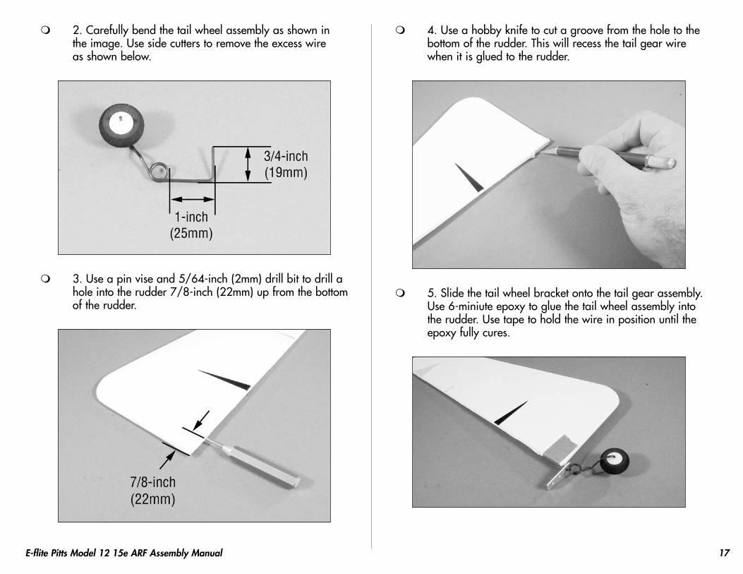
2. Carefully bend the tail wheel assembly as shown in the image. Use side cutters to remove the excess wire as shown below.
3. Use a pin vise and 5/64-inch (2mm) drill bit to drill a hole into the rudder 7/8-inch (22mm) up from the bottom of the rudder.
4. Use a hobby knife to cut a groove from the hole to the bottom of the rudder. This will recess the tail gear wire when it is glued to the rudder.
5. Slide the tail wheel bracket onto the tail gear assembly. Use 6-miniute epoxy to glue the tail wheel assembly into the rudder. Use tape to hold the wire in position until the epoxy fully cures.

18 E-flite Pitts Model 12 15e ARF Assembly Manual
6. Use three CA hinges to attach the rudder to the fin/fuselage as shown. Use the directions as described in "Hinging the Control Surfaces."
7. Use two #2 x 1/2-inch sheet metal screws to attach the tail gear bracket to the fuselage. Make sure the alignment does not bind against the wire when operating the rudder.
Landing Gear InstallationRequired Parts
Fuselage Landing gearWheel pant (2) 3 x 10mm machine screw (3)3mm washer (5) 3mm nut (2)2mm x 6mm sheet metal screw (2)3mm wheel collar w/setscrew (2)3mm x 30mm machine screw (2)
Required Tools and Adhesives6-minute epoxy Hobby knifeThreadlock Phillips screwdriver: #0
1. Remove the landing gear filler block from the fuselage. Attach the landing gear to the fuselage using three 3mm x 10mm machine screws and three 3mm washers. Use threadlock on the screws to prevent them from vibrating loose.

19E-flite Pitts Model 12 15e ARF Assembly Manual
2. Press the landing gear filler block in position. This will transfer the location of the screws onto the block.
3. Use a hobby knife to trim the filler block to clear the heads of the three screws holding the landing gear to the fuselage.
4. Use 6-minute epoxy to glue the filler block in position on the fuselage.
5. Slide a 3mm x 30mm machine screw through the wheel. Use a 3mm wheel collar and setscrew to secure the screw in the wheel. Use threadlock on the setscrew to prevent it from vibrating loose.
20 E-flite Pitts Model 12 15e ARF Assembly Manual
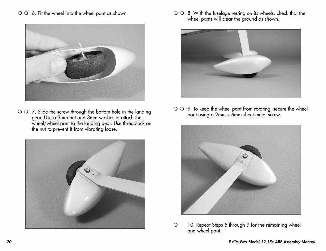
6. Fit the wheel into the wheel pant as shown.
7. Slide the screw through the bottom hole in the landing gear. Use a 3mm nut and 3mm washer to attach the wheel/wheel pant to the landing gear. Use threadlock on the nut to prevent it from vibrating loose.
8. With the fuselage resting on its wheels, check that the wheel pants will clear the ground as shown.
9. To keep the wheel pant from rotating, secure the wheel pant using a 2mm x 6mm sheet metal screw.
10. Repeat Steps 5 through 9 for the remaining wheel and wheel pant.

21E-flite Pitts Model 12 15e ARF Assembly Manual
Radio InstallationRequired Parts
Control horn (4) Control horn backplate (4)Pushrod wire clip (4) Aileron servo block (4)Clevis (4) Long servo arm (2)3mm x 30mm machine screw (2)2mm x 6mm sheet metal screw (8)3
3/4-inch (95mm) pushrod wire (4)Required Tools and Adhesives
Drill Drill bit: 1/16-inch )1.5mm)Hobby knife Servo (4)Felt-tipped pen PliersPin drill Phillips screwdriver: #0Side cutters Thin CA30-minute epoxy Drill bit: 5/64-inch (2mm)9-inch (228mm) servo extension (2)
1. Secure a 9-inch (228mm) servo extension to the servo lead as shown. Use a commercially available connector or some thread to secure the connection.
2. Remove the covering for the opening for the rudder servo. Use the hardware provided with the servo to install it in the fuselage.

22 E-flite Pitts Model 12 15e ARF Assembly Manual
3. Thread a clevis onto a 3 3/4-inch (95mm) pushrod
wire. Attach the clevis to the control horn. Align the pushrod with the servo then use a felt-tipped pen to mark the location for the control horn screws through the control horn.
4. Use a pin drill with a 5/64-inch (2mm) drill bit to drill the holes for the control horn screw.
5. Place a few drops of thin CA into each hole to harden the surrounding wood. This will provide a better base for the control horn when it is installed.
6. Attach the control horn using two 2mm x 10mm machine screws and a control horn backplate.

23E-flite Pitts Model 12 15e ARF Assembly Manual
7. Hold the rudder in neutral. Use the radio to center the rudder servo and make sure the servo arm is perpendicular to the servo center line. Mark the pushrod with a felt-tipped pen where it crosses the outside hole on the servo arm.
8. Bend the pushrod wire 90 degrees at the mark made in the previous step. Secure the pushrod wire to the servo arm using a pushrod wire clip. Trim any excess pushrod wire to prevent it from rubbing the fuselage or servo with side cutters.

24 E-flite Pitts Model 12 15e ARF Assembly Manual
9. Repeat Steps 1 through 8 for the elevator servo.
10. Install the receiver in the fuselage. Follow the manufacturers installation instructions for proper placement of your receiver. Plug the two extensions for the aileron servos into the receiver at this time as well.
11. Remove the servo cover from the bottom of the bottom wing. Use a hobby knife to remove the covering in the cover for the servo arm.
12. Position the aileron servo onto the cover. Align the servo arm so it exits the opening without binding on the cover during operation. Make the position of the servo on the cover.
25E-flite Pitts Model 12 15e ARF Assembly Manual
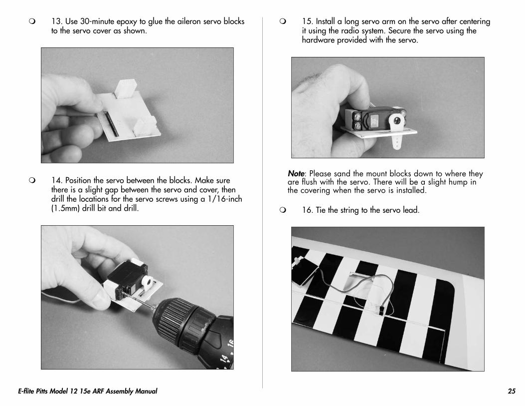
13. Use 30-minute epoxy to glue the aileron servo blocks to the servo cover as shown.
14. Position the servo between the blocks. Make sure there is a slight gap between the servo and cover, then drill the locations for the servo screws using a 1/16-inch (1.5mm) drill bit and drill.
15. Install a long servo arm on the servo after centering it using the radio system. Secure the servo using the hardware provided with the servo.
Note: Please sand the mount blocks down to where they are flush with the servo. There will be a slight hump in the covering when the servo is installed.
16. Tie the string to the servo lead.

26 E-flite Pitts Model 12 15e ARF Assembly Manual
17. Pull the servo lead through the wing using the string. Use tape to keep the lead from falling back into the wing.
18. Use a drill and 1/16-inch (1.5mm) drill to drill a hole at each of the corners of the servo cover and into the supports. Use four 2mm x 6mm sheet metal screws to secure the servo cover to the wing.
19. Use a 3 3/4-inch (95mm) pushrod wire, clevis and
pushrod rod wire clip to assemble and install the linkage between the servo and control horn. Position the control horn on the aileron so the linkage is perpendicular to the hinge line. You will need to install the control horn on the aileron before installing the linkage.
27E-flite Pitts Model 12 15e ARF Assembly Manual
Motor InstallationRequired Parts
Fuselage Cowling2mm x 6mm sheet metal screw Hook and loop strap (2)
Required Tools and AdhesivesMotor w/X-mount & hardware DrillDrill bit: 1/16-inch (1.5mm) PropellerPhillips screwdriver: #0, #1 Hex wrench: 3/32-inch6-minute epoxy Threadlock
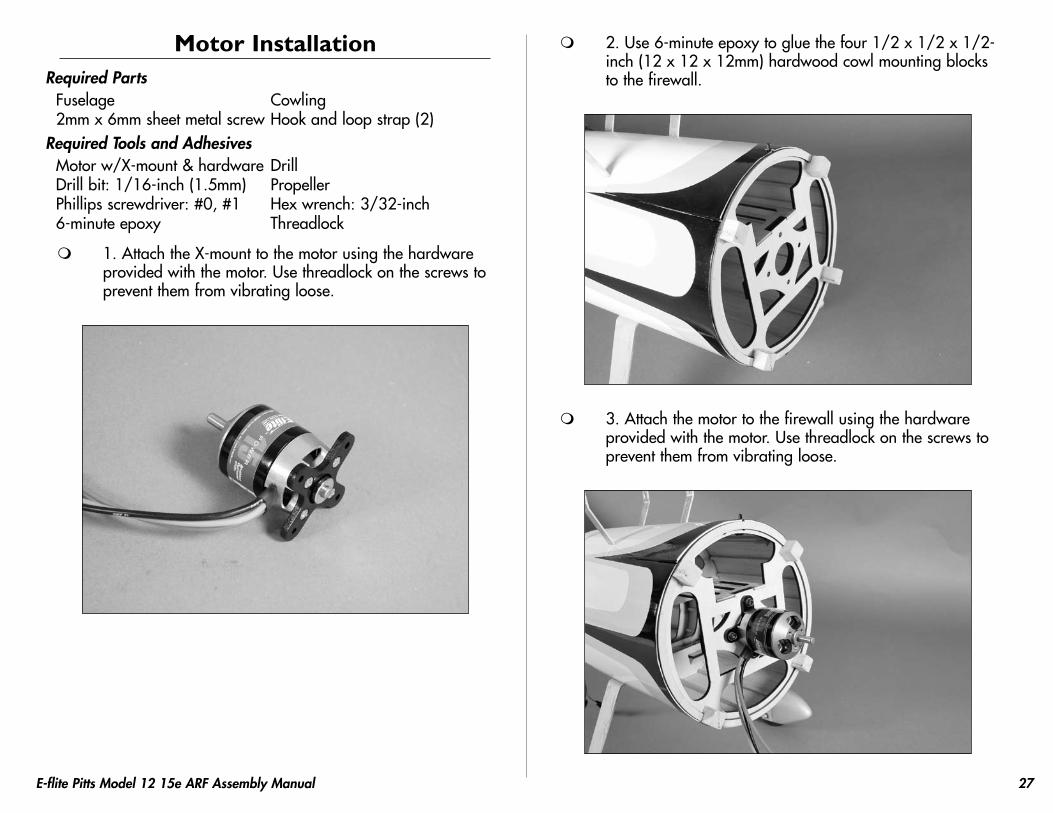
1. Attach the X-mount to the motor using the hardware provided with the motor. Use threadlock on the screws to prevent them from vibrating loose.
2. Use 6-minute epoxy to glue the four 1/2 x 1/2 x 1/2-inch (12 x 12 x 12mm) hardwood cowl mounting blocks to the firewall.
3. Attach the motor to the firewall using the hardware provided with the motor. Use threadlock on the screws to prevent them from vibrating loose.

28 E-flite Pitts Model 12 15e ARF Assembly Manual
4. Plug the motor into the speed control. Secure the speed control under the battery tray.
5. Secure the motor battery in the fuselage using the hook and loop straps.
6. Use a drill and 1/16-inch drill bit to drill holes through the cowl and into the cowl mounting blocks. Secure the cowl using four 2mm x 6mm sheet metal screws.
Important Information About Your Brushless ESC
Make sure your ESC brake is programmed to Off. Also, be sure to use an ESC with the proper low-voltage cutoff and it is set correctly for the batteries you are using.
7. Turn on the radio system and plug the battery into the speed control. Use the throttle to check that the motor rotates counterclockwise when viewed from the front. If not, follow the directions included with your speed control to change the direction of the motor rotation.
Note: Never check the motor rotation on the bench with the propeller installed. The plane could move and cause serious injury. Always check the motor without the propeller to avoid injury.

29E-flite Pitts Model 12 15e ARF Assembly Manual
Important Information About Your Propeller
It is also very important to check to be sure the propeller is balanced before installing onto the shaft. An unbalanced propeller may strip the gears or cause poor flight characteristics.
Note: If it is necessary to enlarge the hole in the propeller, make sure to check the balance of the propeller afterwards.
8. Use a hobby knife and rotary tool to remove the area in the center of the dummy radial engine. Use a hobby knife to remove the area between each of the cylinders to allow cooling air to pass through the cowling and over the motor. Use 6-minute epoxy to glue the dummy radial engine inside the cowling.
9. Install the propeller using the adapter provided with your motor.

30 E-flite Pitts Model 12 15e ARF Assembly Manual
Final Detail InstallationRequired Parts
Fuselage Air IntakePlywood aileron horn (4) Clevis (2)Pushrod connector (2) 2mm x 10mm machine screw (5)2mm nut (5) 2mm x 8mm sheet metal screw (2)Lower fin extension7
3/4-inch (197mm) pushrod wire (2)Required Tools and Adhesives
Medium CA Hobby knifeCanopy glue Tape
1. Use medium CA to glue the air intake to the bottom of the fuselage. Make sure not to glue the intake to the cowl.
Note: Your intake scoop will differ slightly from the one pictured above. It will be black in color as well, not white as depicted in the photo. These changes were made to ensure the accuracy of the full scale Pitts model 12 was maintained.
2. Install the pushrod connector in the bottom control horn. The screw will face toward the wing tip.
3. Thread a clevis on the pushrod wire. Connect the clevis to the control horn of the top wing. With both ailerons centered, tighten the screw to secure the pushrod to the pushrod connector.

31E-flite Pitts Model 12 15e ARF Assembly Manual
4. Use canopy glue to attach the canopy to the fuselage. Use tape to hold the canopy in position until the glue fully cures.
Optional AccessoriesNote: The tail surface flying wires are included for you to add if you desire. They are not required for everyday flight or even 3D flight.
1. Attach the flying wires to the fin and stabilizer using 2mm x 10mm machine screws and 2mm nuts. Use threadlock on the nuts to prevent them from vibrating loose.

32 E-flite Pitts Model 12 15e ARF Assembly Manual
2. The flying wires are attached to the bottom of the stabilizer using 2mm x 10mm machine screws. They are then attached to the fuselage using two 2mm x 8mm sheet metal screws.
3. Use medium CA to glue the lower fin extension to the bottom of the fuselage.
Note: The clear fin extensions are included to enhance the 3D flight envelope. Quique designed these and found them to help the model in inverted harriers as well as extreme yaw control during other high alpha manevers.
Control ThrowsUse a ruler to adjust the throw of the elevator, ailerons and rudder. Adjust the position of the pushrod at the control horn to achieve the following measurements when moving the sticks to their endpoints.
Note: Measurements are taken at the widest point on the surface.
AileronsHigh Rate: 1
1/8-inch (29mm) (Up/Down)
Low Rate: 1/2-inch (12mm) (Up/Down)
ElevatorHigh Rate: 1
3/4-inch (44mm) (Up/Down)
Low Rate: 1-inch (25mm) (Up/Down)
RudderHigh Rate: 2
7/8-inch (73mm) (Right/Left)
Low Rate: 1-inch (25mm) (Right/Left)
These are general guidelines measured from our own flight tests. You can experiment with higher rates to match your preferred style of flying.

33E-flite Pitts Model 12 15e ARF Assembly Manual
Center of GravityAn important part of preparing the aircraft for flight is properly balancing the model.
Caution: Do not inadvertently skip this step!
The recommended Center of Gravity (CG) location for the Pitts Model 12 15e ARF is 3
3/4– 4 1/8-inch (95–105mm) back from
the leading edge of the top wing.
Use the 3 3/4-inch (95mm) CG for sport/scale flying and the
4 1/8-inch (105mm) CG for 3D aerobatic flying.
After the first flights, the CG position can be adjusted for your personal preference.
Range Test Your Radio 1. Before each flying session, be sure to range check your
radio. This is accomplished by turning on your transmitter with the antenna collapsed. Turn on the receiver in your airplane. With your airplane on the ground and the engine running, you should be able to walk 30 paces (approximately 100 feet) away from your airplane and still have complete control of all functions.
If not, don’t attempt to fly! Have your radio equipment checked out by the manufacturer.
2. Double-check that all controls (aileron, elevator, rudder and throttle) move in the correct direction.
3. Be sure that your transmitter batteries are fully charged, per the instructions included with your radio.
Quique Somenzini's Statement about the Pitts Model 12
The Pitts model 12 will give you what you need, a wide range of airspeed and aerobatics. Today's aerobatics requires what the Pitts's has, superb top speed and incredible low speed through the entire flight envelope. Along this wide speed envelope the Pitts does it with rock solid stability on all three axis with clean controls and minimum coupling. This aircraft will give you a unique feeling of good looks and performance all the time. This great look and feeling is present from take off to landing, as if you were flying a true mixture of biplane/monoplane!!.
The E-flite power plant delivers enough watts to make the Pitts climb and accelerate with authority giving the Pitts the look of a true unlimited performer.
I enjoy this biplane as it has scale appeal an can perform such clean aerobatic lines!.

34 E-flite Pitts Model 12 15e ARF Assembly Manual
PreflightCheck Your Radio
Before going to the field, be sure that your batteries are fully charged per the instructions included with your radio. Charge both the transmitter and receiver pack for your airplane. Use the recommended charger supplied with your particular radio system, following the instructions provided with the radio. In most cases, the radio should be charged the night before going out flying.
Before each flying session, be sure to range check your radio. See your radio manual for the recommended range and instructions for your radio system. Each radio manufacturer specifies different procedures for their radio systems. Next, start the motor. With the model securely anchored, check the range again. The range test should not be significantly affected. If it is, don’t attempt to fly! Have your radio equipment checked out by the manufacturer.
Note: Keep loose items that can get entangled in the propeller away from the prop. These include loose clothing, or other objects such as pencils and screwdrivers. Especially keep your hands away from the propeller.
Double-check that all controls (aileron, elevator, rudder and throttle) move in the correct direction.
Check the radio installation and make sure all the control surfaces are moving correctly (i.e. the correct direction and with the recommended throws). Test run the motor and make sure it transitions smoothly from off to full throttle and back. Also ensure the engine is installed according to the manufacturer’s instructions, and it will operate consistently.
Check all the control horns, servo horns, and clevises to make sure they are secure and in good condition. Replace any items that would be considered questionable. Failure of any of these components in flight would mean the loss of your aircraft.
Flying Your Pitts Model 12 15e ARFFlying the Pitts Model 12 15e ARF is about as fun as it can get. A very light wing loading and extreme control throws make for some exciting 3D flying. Verify that your CG is at the correct location as per the manual and that you have your rates set up to your liking. Verify all control throws are in the correct direction and the motor spins in the correct direction as well.
Point the model into the wind and add some throttle trim until the motor begins to turn. This will be your flight idle. Now, apply power slowly. You will find the model will become airborne very quickly and at a low speed. This model excels at flying slow and easy as well as fast and extreme. Trim the model for level flight at half throttle. Only use full throttle for maneuvering.
You will find you can adjust the CG to your liking by moving the battery pack fore or aft on the fuselage. Also keep the battery on the fuselage mounted high (at least at wing centerline or above) to help in hovering maneuvers and harriers.
To land the Pitts Model 12 15e ARF, just reduce the throttle to idle and feed in up elevator until the model settles into a slightly nose-high attitude. Gently fly the model down to the landing spot with a final flair at touchdown. You will find the model will have a very short roll out. We hope you enjoy the Pitts Model 12 15e ARF as much as we do.
Happy landings.

35E-flite Pitts Model 12 15e ARF Assembly Manual
2007 Official AMA National Model Aircraft Safety Code
GENERAL1) I will not fly my model aircraft in sanctioned events, air shows
or model flying demonstrations until it has been proven to be airworthy by having been previously, successfully flight tested.
2) I will not fly my model higher than approximately 400 feet within 3 miles of an airport without notifying the airport operator. I will give right-of-way and avoid flying in the proximity of full-scale aircraft. Where necessary, an observer shall be utilized to supervise flying to avoid having models fly in the proximity of full-scale aircraft.
3) Where established, I will abide by the safety rules for the flying site I use, and I will not willfully or deliberately fly my models in a careless, reckless and/or dangerous manner.
4) The maximum takeoff weight of a model is 55 pounds, except models flown under Experimental Aircraft rules.
5) I will not fly my model unless it is identified with my name and address or AMA number on or in the model. (This does not apply to models while being flown indoors.)
6) I will not operate models with metal-bladed propellers or with gaseous boosts, in which gases other than air enter their internal combustion engine(s); nor will I operate models with extremely hazardous fuels such as those containing tetranitromethane or hydrazine.
RADIO CONTROL1) I will have completed a successful radio equipment ground range
check before the first flight of a new or repaired model.2) I will not fly my model aircraft in the presence of spectators until I
become a qualified flier, unless assisted by an experienced helper.3) At all flying sites a straight or curved line(s) must be established
in front of which all flying takes place with the other side for spectators. Only personnel involved with flying the aircraft are allowed at or in front of the flight line. Intentional flying behind the flight line is prohibited.
4) I will operate my model using only radio control frequencies currently allowed by the Federal Communications Commission. (Only properly licensed Amateurs are authorized to operate equipment on Amateur Band frequencies.)
5) Flying sites separated by three miles or more are considered safe from site-to-site interference, even when both sites use the same frequencies. Any circumstances under three miles separation require a frequency management arrangement, which may be either an allocation of specific frequencies for each site or testing to determine that freedom from interference exists. Allocation plans or interference test reports shall be signed by the parties involved and provided to AMA Headquarters.
Documents of agreement and reports may exist between (1) two or more AMA Chartered Clubs, (2) AMA clubs and individual AMA members not associated with AMA Clubs, or (3) two or more individual AMA members.
6) For Combat, distance between combat engagement line and spectator line will be 500 feet per cubic inch of engine displacement. (Example: .40 engine = 200 feet.); electric motors will be based on equivalent combustion engine size. Additional safety requirements will be per the RC Combat section of the current Competition Regulations.
7) At air shows or model flying demonstrations, a single straight line must be established, one side of which is for flying, with the other side for spectators.
8) With the exception of events flown under AMA Competition rules, after launch, except for pilots or helpers being used, no powered model may be flown closer than 25 feet to any person.
9) Under no circumstances may a pilot or other person touch a powered model in flight.

10491
© 2007 Horizon Hobby, Inc. 4105 Fieldstone Road
Champaign, Illinois 61822 (877) 504-0233
horizonhobby.com E-fliteRC.com