PISa powered two wheeler integrated safety: development … · PISa – Powered two-wheeler...
18
•
Transcript of PISa powered two wheeler integrated safety: development … · PISa – Powered two-wheeler...

Loughborough UniversityInstitutional Repository
PISa � powered two wheelerintegrated safety:
development, implementationand testing of PTW
integrated safety systems
This item was submitted to Loughborough University's Institutional Repositoryby the/an author.
Citation: SAVINO, G. ... et al, 2010. PISa � powered two wheeler integratedsafety: development, implementation and testing of PTW integrated safetysystems. IN: Proceedings of 8th International Motorcycle Conference, N14,Cologne, Germany, 4th-5th October, pp. 186-210.
Additional Information:
• This is a conference paper.
Metadata Record: https://dspace.lboro.ac.uk/2134/8451
Version: Accepted for publication
Publisher: c© Institute for Motorcyle Safety (ifz)
Please cite the published version.

This item was submitted to Loughborough’s Institutional Repository (https://dspace.lboro.ac.uk/) by the author and is made available under the
following Creative Commons Licence conditions.
For the full text of this licence, please go to: http://creativecommons.org/licenses/by-nc-nd/2.5/

1
8th
International Motorcycle Conference, Cologne 4/5 October 2010
PISa – Powered two-wheeler Integrated Safety.
Development, implementation and testing of PTW integrated safety systems
Authors (name and surname):
Giovanni Savino & Marco Pierini1; Rachel Grant, Richard Frampton & Rachel Talbot
2; Steffen Peldschus &
Erich Schuller3; Aernout Oudenhuijzen & Jasper Pauwelussen
4; Bart Scheepers & Arjan Teerhuis
5; Mangaraju
Karanam Venkata & Rengarajan Babu6; Bernd Roessler
7; Matteo Nanetti
8; Roberto Guggia
9; Michael G.
McCarthy & Wesley Hulshof10
Affiliations: 1 Dipartimento di Meccanica e Tecnologie Industriali, Università degli Studi di Firenze, Italy.
2 Vehicle Safety Research Centre, Loughborough University, UK.
3 Institute of Legal Medicine, Ludwig-Maximilians University, Germany.
4 Human Factors, TNO, The Netherlands.
5 Automotive, Integrated Safety, TNO, The Netherlands.
6 TVS Motor Company Limited, India.
7 Ibeo Automotive Systems GmbH, Germany.
8 Paioli Meccanica S.p.A., Italy.
9 Unilab Laboratori Industriali s.r.l., Italy.
10 Vehicle Safety and Engineering, TRL Limited, UK.
Abstract
The Powered two wheeler Integrated Safety (PISa) project, funded by the European Commission within the
6th Framework, aimed at identifying, developing and testing new technologies to provide integrated safety
systems (ISS) for a range of powered two wheelers (PTWs) to improve primary safety and link to secondary
safety systems.
From the analysis of representative crashes involving motorcycles and mopeds, a list of safety systems was
prioritised in terms of their contribution to crash avoidance or injury severity reduction. These systems were
integrated onto two different types of PTW: a large scooter and a light motorcycle.
Experimental tests with the demonstration vehicles showed the potential benefits of the PISa systems
compared to unequipped PTWs. Further system development is required before testing the demonstration
vehicles with non-professional riders.
Introduction
The large number of road accidents represents one of the concerns of the European Commission (EC). In
2001, there were almost 50.000 road fatalities in Europe; more than 5,000 of these were powered two wheeler
(PTW) riders or pillion riders. In the same year, the EC signed the White paper – „European transport policy for
2010: time to decide‟, expressing its commitment to sustain the development of new technologies aiming at
drastically reducing the number of the road accidents and fatalities. PISa – Powered two wheeler integrated
Safety, which started in June 2006 and ended in March 2010, was one of the EC funded projects in the field of
road safety and aimed to develop and use new technologies to provide an integrated safety system for a range of
PTWs.
The philosophy of the PISa project was to identify the most frequent causes of PTW accidents and select the
technologies capable of supporting the riders in critical situations. The review of the previous studies on
European PTW accident statistics provided the basis to investigate the most relevant crash types for PTWs in
terms of frequency and severity. These were mainly the crashes involving a PTW and a car travelling along the
same straight line or approaching a junction from different directions. The systems developed in the PISa
project were selected to help riders avoid some of those types of crash and mitigate the consequences of others,
thus leading to a reduction in serious injuries.
The integrated approach of PISa consisted in the combination of accident avoidance and injury prevention
technologies. Two different integrated systems were implemented, both focused on the identification of hazard
and enhanced braking combined with the PTW stability, although with different levels of technical complexity
and cost.
2
Method
Identification of the integrated safety system
The approach taken to identify an effective integrated safety system consisted of analysis of a sample of
representative crashes which took place in Europe and involved PTWs. Sixty crashes were selected from British
and German in-depth accident databases with the main criterion of matching the most frequent accident
scenarios identified by the APROSYS project. Each crash was examined to identify relevant safety functions
addressing the pre-crash, crash or post-crash phase, which could have helped to avoid the crash or in mitigating
the injury outcome. A list of 43 safety functions was obtained, taking into account both the available automotive
technologies and new functions. The safety functions were prioritised by a team of analysts in terms of the
contribution to crash avoidance or injury severity reduction for the in-depth crashes. The process was based on
the frequency of occurrence and how effective the actions of the system were judged to be in the specific
accident circumstances. Among the high priority safety functions, only those which could be installed on a
PTW (as opposed to other vehicles or infrastructures) were selected for development. The prioritised safety
functions were utilised to define the functional requirements for the development of the integrated safety
system. A complimentary survey among motorcyclists in Germany, Italy and the Netherlands was conducted to
investigate what the possible rider acceptance of a selection of these safety functions might be.
The safety functions selected for the integrated safety system were:
Stop PTW - autonomous braking
PTW to detect other vehicle and warn rider - laser scanner
Anti-lock braking system (ABS)
Brake Assist - enhanced braking system (EB)
Brake Assist - combined braking system/linked brakes (CB)
Adaptive cruise control (ACC)
Active/anti-dive suspension was also identified, in order to support the operation of the systems identified
above.
These safety functions were applied to 2 different PTWs in different combinations as described below.
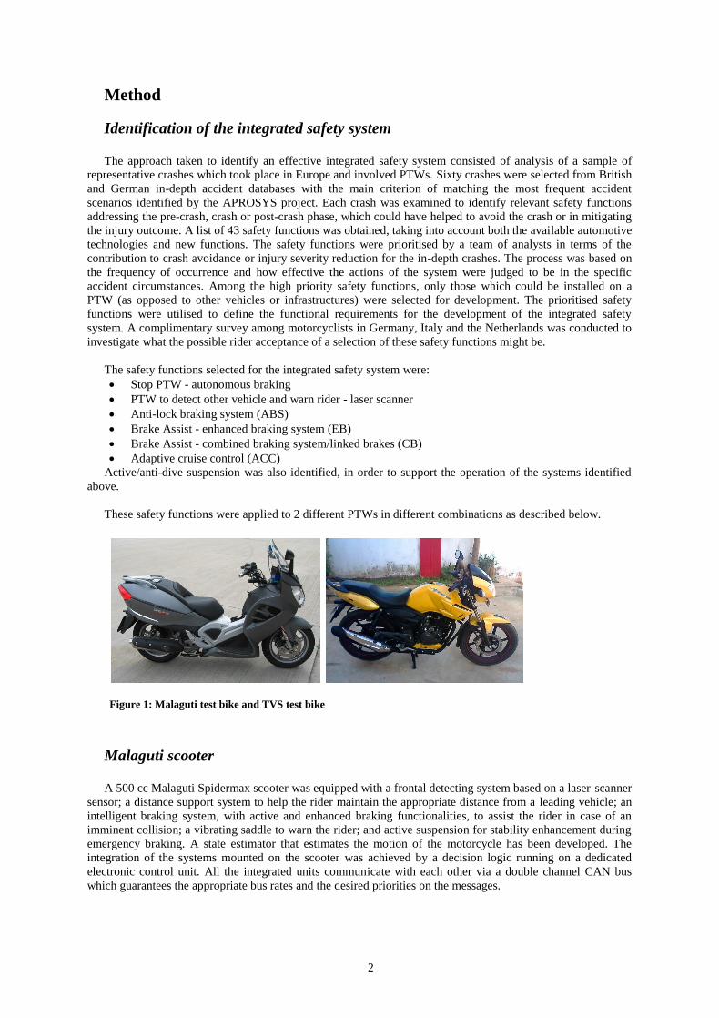
Figure 1: Malaguti test bike and TVS test bike
Malaguti scooter
A 500 cc Malaguti Spidermax scooter was equipped with a frontal detecting system based on a laser-scanner
sensor; a distance support system to help the rider maintain the appropriate distance from a leading vehicle; an
intelligent braking system, with active and enhanced braking functionalities, to assist the rider in case of an
imminent collision; a vibrating saddle to warn the rider; and active suspension for stability enhancement during
emergency braking. A state estimator that estimates the motion of the motorcycle has been developed. The
integration of the systems mounted on the scooter was achieved by a decision logic running on a dedicated
electronic control unit. All the integrated units communicate with each other via a double channel CAN bus
which guarantees the appropriate bus rates and the desired priorities on the messages.

3
Figure 2: Scheme of the integrated safety system mounted on the Malaguti scooter
Laserscanner
The main task of the object detection sensor system was to detect, classify and track the objects in the
PTW‟s forward field of view. This information is later used in the control level in order to interpret the situation
and to issue warnings to the driver, or to activate autonomous actions within the scenarios addressed by the
PISa project.
The “heart” of the system was the Ibeo Lux Laser scanner. This device uses a time-of-flight measurement
principle at near-infrared wavelength. The measurement range is up to 200 m, however vehicles and other well
reflecting objects are typically detected well beyond this distance. The device is eye-safe (class 1) and has the
following features:
• Scan frequency: 12.5/25 Hz
• Field of view (horizontal): 100°
• Range: 0.3 m to 200 m
• Resolution angle: 0.1° to 1°
• Laser class 1
• Built-in processing
• 4 parallel and simultaneous scanning layers
• Ethernet- and CAN-interface
Figure 3: Ibeo Lux Laserscanner
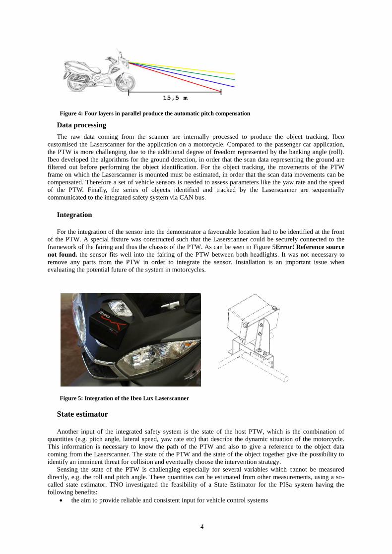
The Laserscanner is capable of full automatic pitch compensation, due to four laser beams working in
parallel and simultaneously which produce a vertical field of view of 3.2°. The four beams allow the object
tracking while the PTW is pitching and make the system robust for rough road surfaces.
4
Figure 4: Four layers in parallel produce the automatic pitch compensation
Data processing
The raw data coming from the scanner are internally processed to produce the object tracking. Ibeo
customised the Laserscanner for the application on a motorcycle. Compared to the passenger car application,
the PTW is more challenging due to the additional degree of freedom represented by the banking angle (roll).
Ibeo developed the algorithms for the ground detection, in order that the scan data representing the ground are
filtered out before performing the object identification. For the object tracking, the movements of the PTW
frame on which the Laserscanner is mounted must be estimated, in order that the scan data movements can be
compensated. Therefore a set of vehicle sensors is needed to assess parameters like the yaw rate and the speed
of the PTW. Finally, the series of objects identified and tracked by the Laserscanner are sequentially
communicated to the integrated safety system via CAN bus.
Integration
For the integration of the sensor into the demonstrator a favourable location had to be identified at the front
of the PTW. A special fixture was constructed such that the Laserscanner could be securely connected to the
framework of the fairing and thus the chassis of the PTW. As can be seen in Figure 5Error! Reference source
not found. the sensor fits well into the fairing of the PTW between both headlights. It was not necessary to
remove any parts from the PTW in order to integrate the sensor. Installation is an important issue when
evaluating the potential future of the system in motorcycles.
Figure 5: Integration of the Ibeo Lux Laserscanner
State estimator
Another input of the integrated safety system is the state of the host PTW, which is the combination of
quantities (e.g. pitch angle, lateral speed, yaw rate etc) that describe the dynamic situation of the motorcycle.
This information is necessary to know the path of the PTW and also to give a reference to the object data
coming from the Laserscanner. The state of the PTW and the state of the object together give the possibility to
identify an imminent threat for collision and eventually choose the intervention strategy.
Sensing the state of the PTW is challenging especially for several variables which cannot be measured
directly, e.g. the roll and pitch angle. These quantities can be estimated from other measurements, using a so-
called state estimator. TNO investigated the feasibility of a State Estimator for the PISa system having the
following benefits:
the aim to provide reliable and consistent input for vehicle control systems
5
estimate signals that are not measured directly
compensate for sensor inaccuracy and noise
perform sensor fault detection
reduce the cost of the measurement system by minimizing the number of required sensors
enable the use of lower resolution sensors.
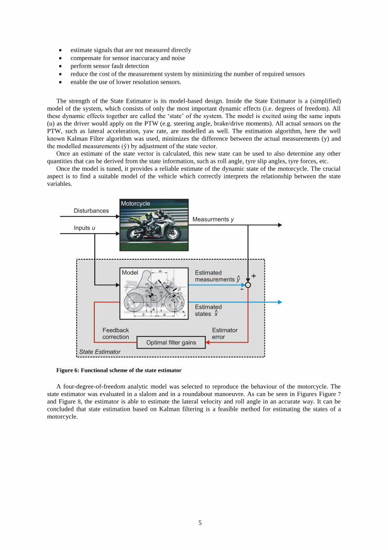
The strength of the State Estimator is its model-based design. Inside the State Estimator is a (simplified)
model of the system, which consists of only the most important dynamic effects (i.e. degrees of freedom). All
these dynamic effects together are called the „state‟ of the system. The model is excited using the same inputs
(u) as the driver would apply on the PTW (e.g. steering angle, brake/drive moments). All actual sensors on the
PTW, such as lateral acceleration, yaw rate, are modelled as well. The estimation algorithm, here the well
known Kalman Filter algorithm was used, minimizes the difference between the actual measurements (y) and
the modelled measurements (ŷ) by adjustment of the state vector.
Once an estimate of the state vector is calculated, this new state can be used to also determine any other
quantities that can be derived from the state information, such as roll angle, tyre slip angles, tyre forces, etc.
Once the model is tuned, it provides a reliable estimate of the dynamic state of the motorcycle. The crucial
aspect is to find a suitable model of the vehicle which correctly interprets the relationship between the state
variables.
Figure 6: Functional scheme of the state estimator
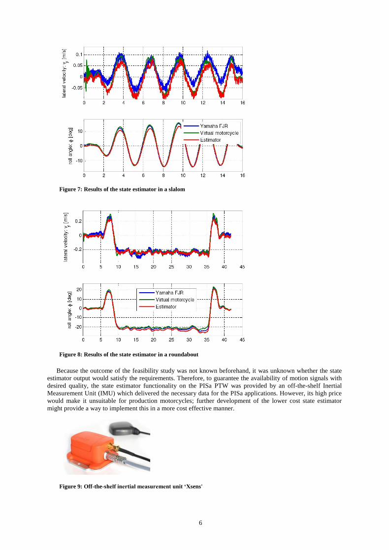
A four-degree-of-freedom analytic model was selected to reproduce the behaviour of the motorcycle. The
state estimator was evaluated in a slalom and in a roundabout manoeuvre. As can be seen in Figures Figure 7
and Figure 8, the estimator is able to estimate the lateral velocity and roll angle in an accurate way. It can be
concluded that state estimation based on Kalman filtering is a feasible method for estimating the states of a
motorcycle.
6
Figure 7: Results of the state estimator in a slalom
Figure 8: Results of the state estimator in a roundabout
Because the outcome of the feasibility study was not known beforehand, it was unknown whether the state
estimator output would satisfy the requirements. Therefore, to guarantee the availability of motion signals with
desired quality, the state estimator functionality on the PISa PTW was provided by an off-the-shelf Inertial
Measurement Unit (IMU) which delivered the necessary data for the PISa applications. However, its high price
would make it unsuitable for production motorcycles; further development of the lower cost state estimator
might provide a way to implement this in a more cost effective manner.
Figure 9: Off-the-shelf inertial measurement unit ‘Xsens'

7
DS system
The Distance Support (DS) system assists the rider to maintain a safe distance during the car-following task
by providing an appropriate force feedback on the throttle twist grip. The basic concept of the DS is that when
the rider maintains the appropriate values of speed and distance from the lead vehicle, the torque on the throttle
is constant. If the lead vehicle slows down, the distance starts to reduce. The attentive rider would react
reducing the torque on the twist grip throttle, while the inattentive rider does not react and keeps a constant
torque, and the gap consequently reduces. The DS system uses the information coming from the IMU and the
Laserscanner to detect the need for slowing down and consequently increases the resistant torque on the handle-
grip, thus reducing the throttle and slowing down the PTW unless the rider reacts.
The human-machine interface based on the force feedback was chosen to fulfil the most important
requirements for a safety application: the rider can react intuitively in a proper way; the rider can keep his/her
eyes on the road without being distracted; the control effort required for the rider should not increase.
The development process consisted of three activities: the definition of the algorithms for controlling the
amount of feedback; the selection of the functional parameters, which are the value of the maximum feedback
torque and the shape followed by the torque to build up; and the development of the hardware to implement the
DS on the test motorcycle.
The intervention algorithm is based on two kinematic algorithms: the time headway (THW) and the time to
collision (TTC). The THW guarantees that the distance between host PTW and lead vehicle is adequate also
when the difference in speed v is zero. The TTC allows identifying the torque feedback when v is different
from zero.
The intervention parameters and the force build-up were selected through an experimental campaign
conducted with a static riding simulator (Figure 10). The volunteers were asked to keep a constant THW during
the car following task simulated by the computer while the throttle twist grip was actuated by an electric motor
to simulate the force feedback produced by the DS system. The volunteers repeated the task while the max
torque and the build-up curve varied; at the end they filled in a questionnaire. The best value for the max torque
and the torque build-up were selected based on the results of the questionnaires.
Figure 10: Riding simulator used during the preliminary tests
The hardware of the DS was developed and tuned to reproduce the prescribed values of torque and the
correct shape to build up the torque. The DS is obtained through a device which exploits the vacuum created by
the engine in the inlet pipe and produces the desired force feedback using intermitting valves. The force
feedback is converted into a torque feedback at the throttle twist grip of the test bike via wire.

8
Figure 11: Operating principle of the DS system
Active Braking
The term active braking (AB), in the context of this project, refers to slowing down the vehicle without any
braking input from the rider i.e. autonomous braking. This system is necessarily linked with the design of the
decision logic.
Laboratory tests were performed by LMU in order to find a feasible level of deceleration for the active
braking. Those sled tests had an idealised set-up mimicking the deceleration process of a PTW in a very basic
way. Based on this experimental activity, a deceleration of 2.5 m/s2 was shown to be adequate in the sense of
not producing excessive motion, or possible instability, of the volunteer riders. This level was then selected as a
target deceleration for the active braking. For the enhanced braking (EB), the target deceleration was 6 m/s2,
which is the maximum value before experiencing cases of front wheel lock with the Malaguti scooter.
The active braking device was designed and realised by Carver Engineering. It utilises an independent
hydraulic system acting on the right hand disk mounted on the front wheel. The front brake is also under control
of the rider through the left braking disk.
Figure 12: Active braking device
The active braking device consists of a dedicated braking disk, the hydraulic circuit and calliper, an electric
motor and pump to build up the pressure, a pressure sensor, the electronic control unit, and the power supply.
When the active braking is idle, the pump is off and the pressure inside the circuit is close to the atmospheric
value, therefore no braking torque is applied on the right braking disk and the rider has full control of the
braking action on the front wheel. When the electronic control unit receives the input to start the active braking
function, the electric motor connected with the pump is activated, the pump starts building up the pressure in the
braking circuit and the calliper produces a braking torque on the right disk on the front wheel.
The predetermined deceleration dref is obtained controlling the pump in closed loop with the pressure sensor,
so that a target pressure can be achieved. Tests with the prototype were performed to identify the target pressure
needed for obtaining the target deceleration dref.
9
Semi-active front fork
Within the PISa project Paioli developed a different front fork suspension for each prototype vehicle aiming
to improve the stability before and during emergency braking events.
The behaviour of the suspension system was fully reversible although the activation time should be quick
enough to be beneficial since the first phase of the braking manoeuvre.
For the Malaguti bike the requirement for the fork was to be capable of continuous adjustment of the
damping coefficient on a wide range, although the reaction time for a full adjustment is around 0.2 and 0.3 s.
Figure 13: Semi-active front fork installed on the Malaguti
Decision logic
The elaboration of the input signals coming from the sensors and the control of the actuators mounted on the
Malaguti are performed by the decision logic running on a prototyping electronic control unit.
The inputs to the decision logic are summarised as follows:
the state of all the objects detected and tracked by the Laserscanner;
the state of the host PTW provided by the inertial measurement unit;
the rider inputs which are the brake pressures, the throttle position and the steering position.
The decision logic has control over the following devices:
the throttle actuator of the DS system;
the active braking device that implements the active and enhanced braking functionalities;
the semi-active front suspension;
the tactile saddle that generates warning signals to the rider.
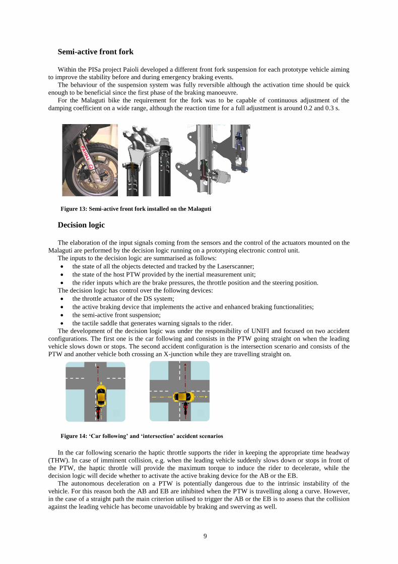
The development of the decision logic was under the responsibility of UNIFI and focused on two accident
configurations. The first one is the car following and consists in the PTW going straight on when the leading
vehicle slows down or stops. The second accident configuration is the intersection scenario and consists of the
PTW and another vehicle both crossing an X-junction while they are travelling straight on.
Figure 14: ‘Car following’ and ‘intersection’ accident scenarios
In the car following scenario the haptic throttle supports the rider in keeping the appropriate time headway
(THW). In case of imminent collision, e.g. when the leading vehicle suddenly slows down or stops in front of
the PTW, the haptic throttle will provide the maximum torque to induce the rider to decelerate, while the
decision logic will decide whether to activate the active braking device for the AB or the EB.
The autonomous deceleration on a PTW is potentially dangerous due to the intrinsic instability of the
vehicle. For this reason both the AB and EB are inhibited when the PTW is travelling along a curve. However,
in the case of a straight path the main criterion utilised to trigger the AB or the EB is to assess that the collision
against the leading vehicle has become unavoidable by braking and swerving as well.
10
The possibility to avoid the collision by braking is evaluated by computing the required deceleration
parameter dreq as follows:
dreq (vPTW vL )
2
2L aL
where vPTW is the PTW speed, vL is the lead vehicle speed, aL is the lead vehicle acceleration, and L is the
relative distance between PTW and leading vehicle. At every instant, dreq represents the constant value of
deceleration the rider should apply to avoid the collision with the leading vehicle assuming that the leading
vehicle is proceeding along a straight line with constant deceleration. The decision logic constantly computes
the value of the required deceleration and compares it with a threshold value representing the maximum feasible
deceleration. When dreq is greater than the threshold the braking avoidance manoeuvre is considered not
possible anymore. The threshold value was initially set to 10 m/s2 which corresponds to the theoretical limit on
dry road conditions with common tyres. During the tests the threshold was adjusted to different values between
3 to 10 m/s2 to investigate the system reliability and the level of acceptance from the test riders.
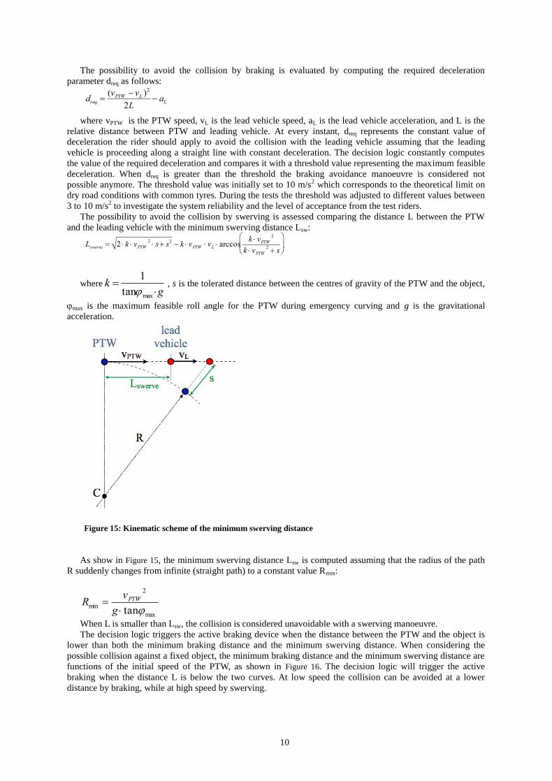
The possibility to avoid the collision by swerving is assessed comparing the distance L between the PTW
and the leading vehicle with the minimum swerving distance Lsw:
Lswerve 2 k vPTW2 s s2 k vPTW vL arccos
k vPTW2
k vPTW2 s
where
k 1
tanmax g , s is the tolerated distance between the centres of gravity of the PTW and the object,
max is the maximum feasible roll angle for the PTW during emergency curving and g is the gravitational
acceleration.
Figure 15: Kinematic scheme of the minimum swerving distance
As show in Figure 15, the minimum swerving distance Lsw is computed assuming that the radius of the path
R suddenly changes from infinite (straight path) to a constant value Rmin:
Rmin vPTW
2
g tanmax
When L is smaller than Lsw, the collision is considered unavoidable with a swerving manoeuvre.
The decision logic triggers the active braking device when the distance between the PTW and the object is
lower than both the minimum braking distance and the minimum swerving distance. When considering the
possible collision against a fixed object, the minimum braking distance and the minimum swerving distance are
functions of the initial speed of the PTW, as shown in Figure 16. The decision logic will trigger the active
braking when the distance L is below the two curves. At low speed the collision can be avoided at a lower
distance by braking, while at high speed by swerving.
11
Figure 16: Minimum braking and swerving distances
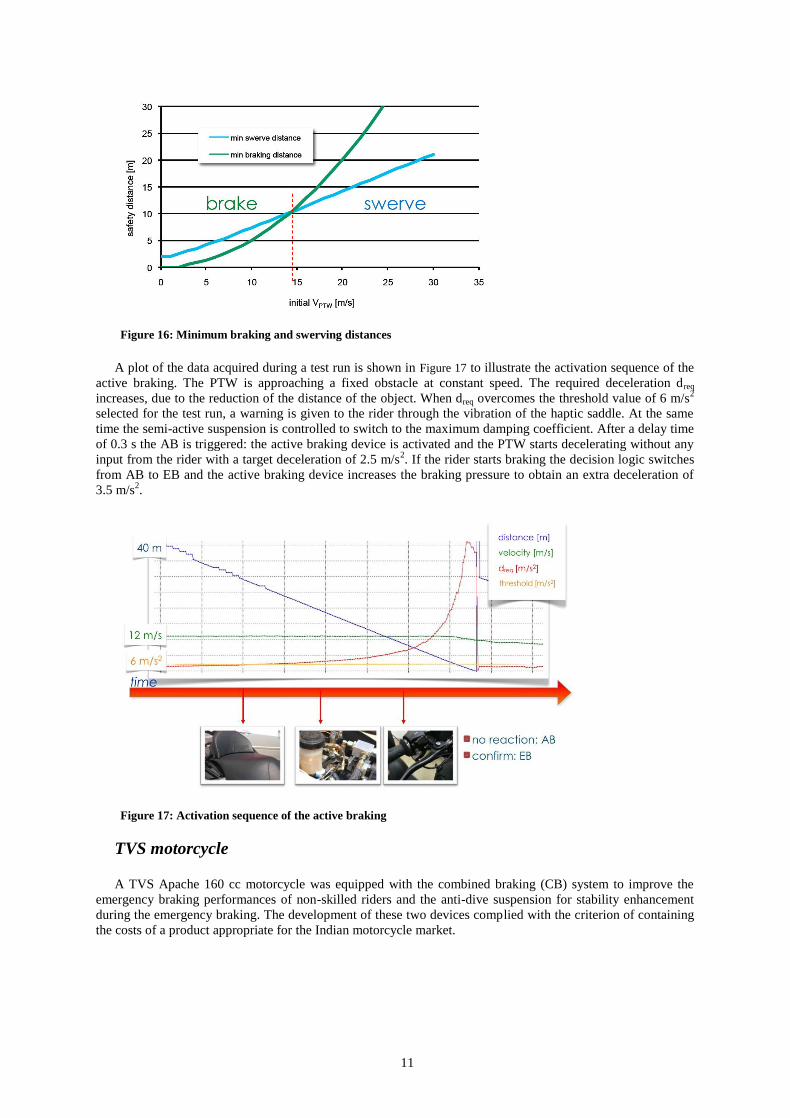
A plot of the data acquired during a test run is shown in Figure 17 to illustrate the activation sequence of the
active braking. The PTW is approaching a fixed obstacle at constant speed. The required deceleration dreq
increases, due to the reduction of the distance of the object. When dreq overcomes the threshold value of 6 m/s2
selected for the test run, a warning is given to the rider through the vibration of the haptic saddle. At the same
time the semi-active suspension is controlled to switch to the maximum damping coefficient. After a delay time
of 0.3 s the AB is triggered: the active braking device is activated and the PTW starts decelerating without any
input from the rider with a target deceleration of 2.5 m/s2. If the rider starts braking the decision logic switches
from AB to EB and the active braking device increases the braking pressure to obtain an extra deceleration of
3.5 m/s2.
Figure 17: Activation sequence of the active braking
TVS motorcycle
A TVS Apache 160 cc motorcycle was equipped with the combined braking (CB) system to improve the
emergency braking performances of non-skilled riders and the anti-dive suspension for stability enhancement
during the emergency braking. The development of these two devices complied with the criterion of containing
the costs of a product appropriate for the Indian motorcycle market.
12
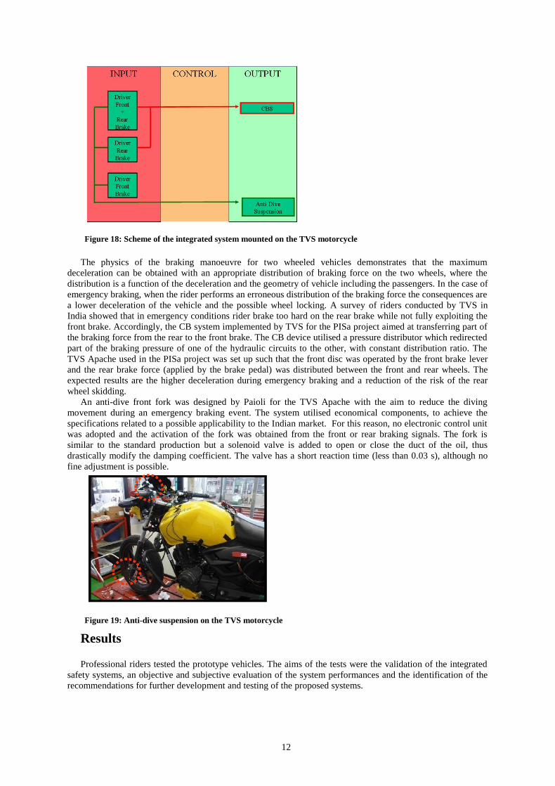
Figure 18: Scheme of the integrated system mounted on the TVS motorcycle
The physics of the braking manoeuvre for two wheeled vehicles demonstrates that the maximum
deceleration can be obtained with an appropriate distribution of braking force on the two wheels, where the
distribution is a function of the deceleration and the geometry of vehicle including the passengers. In the case of
emergency braking, when the rider performs an erroneous distribution of the braking force the consequences are
a lower deceleration of the vehicle and the possible wheel locking. A survey of riders conducted by TVS in
India showed that in emergency conditions rider brake too hard on the rear brake while not fully exploiting the
front brake. Accordingly, the CB system implemented by TVS for the PISa project aimed at transferring part of
the braking force from the rear to the front brake. The CB device utilised a pressure distributor which redirected
part of the braking pressure of one of the hydraulic circuits to the other, with constant distribution ratio. The
TVS Apache used in the PISa project was set up such that the front disc was operated by the front brake lever
and the rear brake force (applied by the brake pedal) was distributed between the front and rear wheels. The
expected results are the higher deceleration during emergency braking and a reduction of the risk of the rear
wheel skidding.
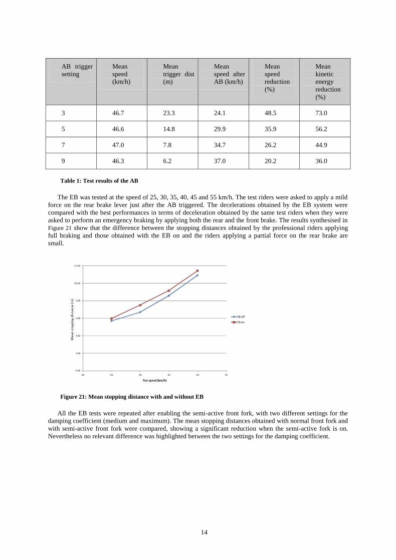
An anti-dive front fork was designed by Paioli for the TVS Apache with the aim to reduce the diving
movement during an emergency braking event. The system utilised economical components, to achieve the
specifications related to a possible applicability to the Indian market. For this reason, no electronic control unit
was adopted and the activation of the fork was obtained from the front or rear braking signals. The fork is
similar to the standard production but a solenoid valve is added to open or close the duct of the oil, thus
drastically modify the damping coefficient. The valve has a short reaction time (less than 0.03 s), although no
fine adjustment is possible.
Figure 19: Anti-dive suspension on the TVS motorcycle
Results
Professional riders tested the prototype vehicles. The aims of the tests were the validation of the integrated
safety systems, an objective and subjective evaluation of the system performances and the identification of the
recommendations for further development and testing of the proposed systems.

13
Results from the Malaguti test programme
For the Malaguti, the tests focussed on the DS, the AB and the EB systems. The final tests of the Malaguti
vehicle were conducted on the TRL research track.
The validation of the DS system consisted of an experiment with the rider simulator and a pilot test on the
track. In both the experiments the subject was asked to perform a car following task with and without the DS
system. The experiments with the rider simulator showed that the DS could significantly improve the ability of
the rider to maintain the target THW from the lead vehicle. In addition, when the DS system was on the throttle
position was more stable, thus showing that the DS is capable of reducing the control effort of the rider during
the car following task.
Figure 20: Simulation tests with and without DS: TTC vs. THW and frequencies of the throttle position
In contrast, the track tests conducted with 5 subjects were not able to highlight analogous differences with
and without the use of the DS system. In particular, the standard deviation of the THW during the car following
tests with the DS system on was not significantly lower compared to the tests without the DS. It was noted that
during the track tests the Laserscanner detected other objects apart from the lead vehicle and this problem could
negatively affect the quality of the feedback given to the riders. However, the subjective evaluation of the DS
system made by the riders reported a positive opinion about the usefulness of the system. The final
recommendation was to repeat the track tests with a wider set of test riders and improve the object detection in
order to obtain results which could be better compared with those achieved in the simulation tests.
The AB tests were performed riding the Malaguti at a target speed of 12.5 m/s (45 km/h) towards a static
obstacle. For safety reasons, the activation of the AB was allowed by the decision logic even if the obstacle was
situated within a lateral distance of 3 m from the host vehicle. The threshold for the activation of the AB was set
at the required deceleration of 3, 5, 7 and 9 m/s2, which means that the active braking aimed to deploy when the
collision could be avoided with a constant deceleration of 3, 5, 7 or 9 m/s2. During the tests, the dSPACE device
recorded 34 parameters at a frequency of 50Hz. The recorded data included the state of the host PTW, the
objects detected from the Laserscanner, the inputs from the rider and other computed variables utilised by the
decision logic.
Each test run was analysed to assess the correct identification of the obstacle and the correct deployment of
the AB (successful test). The test runs in which the static obstacle was not identified, the AB failed to trigger or
the AB had a false triggering were considered unsuccessful. The result was that the successful cases varied
between 83% and 100% with thresholds of 3, 5 and 9 m/s2, while they were the 56% for the threshold of 7 m/s
2.
The system did not function correctly mainly because of crashes of the post-processing software of the
Laserscanner or because the Laserscanner picked up incorrect objects.
Considering the successful runs, the AB was able to produce the active deceleration with a mean value of
2.8 m/s2 (sd = 0.7 m/s
2) without any loss of control of the rider. The speed reduction and the kinetic energy
reduction are dependent on the initial speed and their mean values are reported in Table 1.
14
AB trigger
setting
Mean
speed
(km/h)
Mean
trigger dist
(m)
Mean
speed after
AB (km/h)
Mean
speed
reduction
(%)
Mean
kinetic
energy
reduction
(%)
3 46.7 23.3 24.1 48.5 73.0
5 46.6 14.8 29.9 35.9 56.2
7 47.0 7.8 34.7 26.2 44.9
9 46.3 6.2 37.0 20.2 36.0
Table 1: Test results of the AB
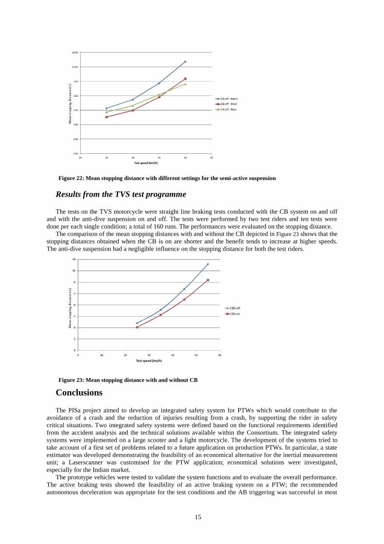
The EB was tested at the speed of 25, 30, 35, 40, 45 and 55 km/h. The test riders were asked to apply a mild
force on the rear brake lever just after the AB triggered. The decelerations obtained by the EB system were
compared with the best performances in terms of deceleration obtained by the same test riders when they were
asked to perform an emergency braking by applying both the rear and the front brake. The results synthesised in
Figure 21 show that the difference between the stopping distances obtained by the professional riders applying
full braking and those obtained with the EB on and the riders applying a partial force on the rear brake are
small.
Figure 21: Mean stopping distance with and without EB
All the EB tests were repeated after enabling the semi-active front fork, with two different settings for the
damping coefficient (medium and maximum). The mean stopping distances obtained with normal front fork and
with semi-active front fork were compared, showing a significant reduction when the semi-active fork is on.
Nevertheless no relevant difference was highlighted between the two settings for the damping coefficient.
15
Figure 22: Mean stopping distance with different settings for the semi-active suspension
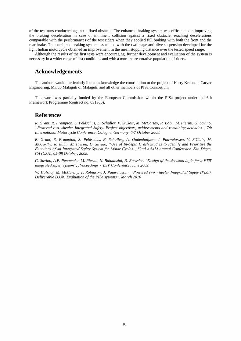
Results from the TVS test programme
The tests on the TVS motorcycle were straight line braking tests conducted with the CB system on and off
and with the anti-dive suspension on and off. The tests were performed by two test riders and ten tests were
done per each single condition; a total of 160 runs. The performances were evaluated on the stopping distance.
The comparison of the mean stopping distances with and without the CB depicted in Figure 23 shows that the
stopping distances obtained when the CB is on are shorter and the benefit tends to increase at higher speeds.
The anti-dive suspension had a negligible influence on the stopping distance for both the test riders.
Figure 23: Mean stopping distance with and without CB
Conclusions
The PISa project aimed to develop an integrated safety system for PTWs which would contribute to the
avoidance of a crash and the reduction of injuries resulting from a crash, by supporting the rider in safety
critical situations. Two integrated safety systems were defined based on the functional requirements identified
from the accident analysis and the technical solutions available within the Consortium. The integrated safety
systems were implemented on a large scooter and a light motorcycle. The development of the systems tried to
take account of a first set of problems related to a future application on production PTWs. In particular, a state
estimator was developed demonstrating the feasibility of an economical alternative for the inertial measurement
unit; a Laserscanner was customised for the PTW application; economical solutions were investigated,
especially for the Indian market.
The prototype vehicles were tested to validate the system functions and to evaluate the overall performance.
The active braking tests showed the feasibility of an active braking system on a PTW; the recommended
autonomous deceleration was appropriate for the test conditions and the AB triggering was successful in most
16
of the test runs conducted against a fixed obstacle. The enhanced braking system was efficacious in improving
the braking deceleration in case of imminent collision against a fixed obstacle, reaching decelerations
comparable with the performances of the test riders when they applied full braking with both the front and the
rear brake. The combined braking system associated with the two-stage anti-dive suspension developed for the
light Indian motorcycle obtained an improvement in the mean stopping distance over the tested speed range.
Although the results of the first tests were encouraging, further development and evaluation of the system is
necessary in a wider range of test conditions and with a more representative population of riders.
Acknowledgements
The authors would particularly like to acknowledge the contribution to the project of Harry Kroonen, Carver
Engineering, Marco Malaguti of Malaguti, and all other members of PISa Consortium.
This work was partially funded by the European Commission within the PISa project under the 6th
Framework Programme (contract no. 031360).
References
R. Grant, R. Frampton, S. Peldschus, E. Schuller, V. StClair, M. McCarthy, R. Babu, M. Pierini, G. Savino,
“Powered two-wheeler Integrated Safety. Project objectives, achievements and remaining activities”, 7th
International Motorcycle Conference, Cologne, Germany, 6-7 October 2008.
R. Grant, R. Frampton, S. Peldschus, E. Schuller,, A. Oudenhuijzen, J. Pauwelussen, V. StClair, M.
McCarthy, R. Babu, M. Pierini, G. Savino, “Use of In-depth Crash Studies to Identify and Prioritise the
Functions of an Integrated Safety System for Motor Cycles”, 52nd AAAM Annual Conference, San Diego,
CA (USA), 05-08 October, 2008.
G. Savino, A.P. Penumaka, M. Pierini, N. Baldanzini, B. Roessler, “Design of the decision logic for a PTW
integrated safety system”, Proceedings - ESV Conference, June 2009.
W. Hulshof, M. McCarthy, T. Robinson, J. Pauwelussen, “Powered two wheeler Integrated Safety (PISa).
Deliverable D33b: Evaluation of the PISa systems”. March 2010