PIR Motion SensorsPyroelectric
24
PIR motion sensors Pyroelectric ("Passive") InfraRed sensors Forums Overview FSR Photocell Temp. Tilt PIR T-Couple IR decode Thermistor DHT BMP085 TSL2561 Buy sensor Home About o ladyada.net o Portfolio o Research o Press o Publication & Presentation o Photos o Wiki (backend) Projects o Arduino » Datalogger Shield Ethernet Shield GPS Shield Proto Shield
Transcript of PIR Motion SensorsPyroelectric

PIR motion sensorsPyroelectric
("Passive") InfraRed sensors
Forums Overview FSR Photocell Temp. Tilt PIR T-Couple IR decode Thermistor DHT BMP085 TSL2561 Buy sensor Home About o ladyada.net
o Portfolio
o Research
o Press
o Publication & Presentation
o Photos
o Wiki (backend)
Projects o Arduino »
Datalogger Shield Ethernet Shield GPS Shield Proto Shield Motor Shield Wave Shield o Adj. power supply
o Brain Machine
o BoArduino
o DIGG Button
o Drawdio
o Fuzebox
o Game Grrl
o Game of Life
o Ice Tube clock

o MIDIsense
o MiniPOV2
o MiniPOV3
o MintyMP3
o MintyBoost
o MONOCHRON
o SIM Reader
o SpokePOV
o TV-B-Gone
o Tweet-a-Watt
o USBtinyISP
o Wave Bubble
o x0xb0x
o XBee
o YBox2
o Quickies »
USB Gamepad Halloween Pumpkin Vintage Bike Lite Kite Arial Photo Bike Stand LiIon Bike Lite Pogo Jib Mass Programming Solar LiPo Charging Magstripe Reader Solar Tracker TRON Bag o More...
o ->Instructables
Learn o Arduino tutorial
o AVR tutorial
o Barcode scanners
o EL Wire tutorial
o LCDs
o LEDs
o Multimeter tutorial
o Digital scales
o Sensors »
FSR CdS Photocell Temperature Tilt PIR Thermocouple IR Receiver o Breakout boards »
DS1307 RTC MAX6675 ATmega32u4 Breakout+ o Products »
i2c/SPI LCD backpack USB Boarduino ATmega32u4 Breakout+ 2.8 TFT touchscreen 1.8 SPI TFT RFID/NFC

o Chumby Hacker Board
o Soldering tutorial
o Power Supply tutorial
o Brother KH-9033 tutorial
o USB reverse-engineering tutorial
o Calipers tutorial
o RGB LED Strips
o RGB LED Pixels
o LiIon & LiPoly Batteries
Library o Arduino Hacks
o Batteries
o Boost Calc
o E.E. Tools
o E.E. Computer
o Find Parts
o Kits
o Laser
o uC Annoyances
o Open Source Hardware
o PCB Design & Tips
o PIC vs. AVR
o Software
o SMT
o Zen-Cart Mods
Blog Store Forums
ladyada.net Search
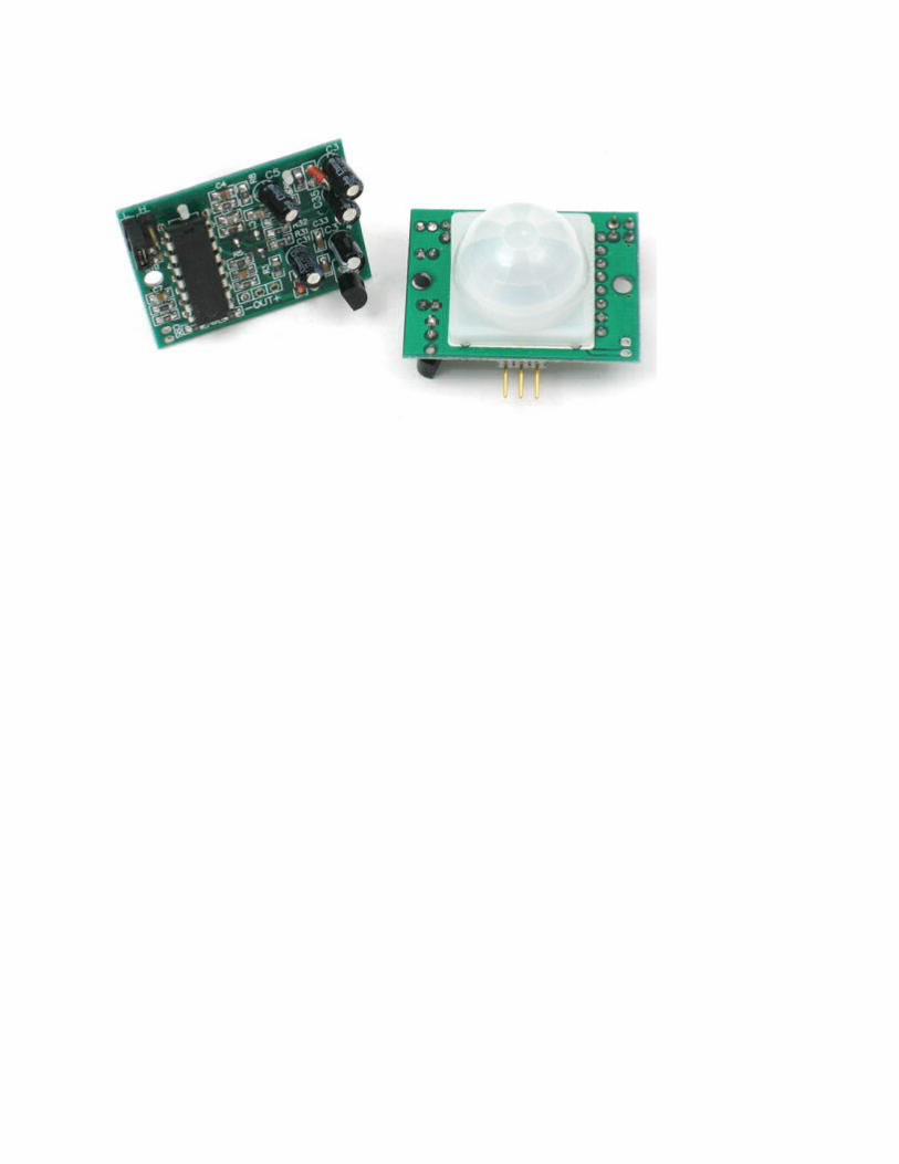
What is a PIR sensor?PIR sensors allow you to sense motion, almost always used to detect whether a human has moved in or out of the sensors range. They are small, inexpensive, low-power, easy to use and don't wear out. For that reason they are commonly found in appliances and gadgets used in homes or businesses. They are often referred to as PIR, "Passive Infrared", "Pyroelectric", or "IR motion" sensors.
PIRs are basically made of a pyroelectric sensor (which you can see above as the round metal can with a rectangular crystal in the center), which can detect levels of infrared radiation. Everything emits some low level radiation, and the hotter something is, the more radiation is emitted. The sensor in a motion detector is actually split in two halves. The reason for that is that we are looking to detect motion (change) not average IR levels. The two halves are wired up so that they cancel each other out. If one half sees more or less IR radiation than the other, the output will swing high or low.Along with the pyroelectic sensor is a bunch of supporting circuitry, resistors and capacitors. It seems that most small hobbyist sensors use theBISS0001 ("Micro Power PIR Motion Detector IC") , undoubtedly a very
inexpensive chip. This chip takes the output of the sensor and does some minor processing on it to emit a digital output pulse from the analog sensor.For many basic projects or products that need to detect when a person has left or entered the area, or has approached, PIR sensors are great. They are low power and low cost, pretty rugged, have a wide lens range, and are easy to interface with. Note that PIRs won't tell you how many people are around or how close they are to the sensor, the lens is often fixed to a certain sweep and distance (although it can be hacked somewhere) and they are also sometimes set off by housepets. Experimentation is key!
Some basic statsThese stats are for the PIR sensor in the Adafruit shop which is very much like the Parallax one . Nearly all PIRs will have slightly different specifications, although they all pretty much work the same. If there's a datasheet, you'll want to refer to it
Size: Rectangular Price: $10.00 at the Adafruit shop Output: Digital pulse high (3V) when triggered (motion detected) digital low when idle (no
motion detected). Pulse lengths are determined by resistors and capacitors on the PCB and differ from sensor to sensor.
Sensitivity range: up to 20 feet (6 meters) 110° x 70° detection range Power supply:3.3V - 5V input voltage, BIS0001 Datasheet (the decoder chip used) RE200B datasheet (most likely the PIR sensing element used) NL11NH datasheet (equivalent lens used) Parallax Datasheet on their version of the sensor
More links!
A great page on PIR sensors from GLOLAB \\ NYU sensor report
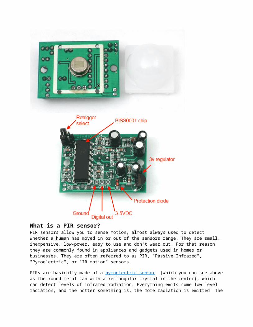
How does it work?PIR sensors are more complicated than many of the other sensors explained in these tutorials (like photocells, FSRs and tilt switches) because there are multiple variables that affect the sensors input and output. To begin explaining how a basic sensor works, we'll use this rather nice diagram (if anyone knows where it originates plz let me know).
The PIR sensor itself has two slots in it, each slot is made of a special material that is sensitive to IR. The lens used here is not really doing much and so we see that the two slots can 'see' out past some distance (basically the sensitivity of the sensor). When the sensor is idle, both slots detect the same amount of IR, the ambient amount radiated from the room or walls or outdoors. When a warm body like a human or animal passes by, it first intercepts one half of the PIR sensor, which causes a positive differential change between the two halves. When the warm body leaves the sensing area, the reverse happens, whereby the sensor generates a negative differential change. These change pulses are what is detected.

[Citation needed]
The PIR sensor itself
Left image from Murata datasheetThe IR sensor itself is housed in a hermetically sealed metal can to improve noise/temperature/humidity immunity. There is a window made of IR-transmissive material (typically coated silicon since that is very easy to come by) that protects the sensing element. Behind the window are the two balanced sensors.
Image from RE200B datasheetYou can see above the diagram showing the element window, the two pieces of sensing material
Image from RE200B datasheetThis image shows the internal schematic. There is actually a JFET inside (a type of transistor) which is very low-noise and buffers the extremely high impedence of the sensors into something a low-cost chip (like the BIS0001) can sense.
LensesPIR sensors are rather generic and for the most part vary only in price and sensitivity. Most of the real magic happens with the optics. This is a pretty good idea for manufacturing: the PIR sensor and circuitry is fixed and costs a few dollars. The lens costs only a few cents and can change the breadth, range, sensing pattern, very easily.
In the diagram up top, the lens is just a piece of plastic, but that means that the detection area is just two rectangles. Usually we'd like to have a detection area that is much larger. To do that, we use a simple lens such as those found in a camera: they condenses a large area (such as a landscape) into a small one (on film or a CCD sensor). For reasons that will be apparent soon, we would like to make the PIR lenses small and thin and moldable from cheap plastic, even though it may add distortion. For this reason the sensors are actually Fresnel lenses :

Image from Sensors Magazine The Fresnel lens condenses light, providing a larger range of IR to the sensor.
Image from BHlens.com
Image from Cypress appnote 2105

OK, so now we have a much larger range. However, remember that we actually have two sensors, and more importantly we dont want two really big sensing-area rectangles, but rather a scattering of multiple small areas. So what we do is split up the lens into multiple section, each section of which is a fresnel lens
Here you can see the multiple facet-sections
This macro shot shows the different Frenel lenses in each facet!The different faceting and sub-lenses create a range of detection areas, interleaved with each other. Thats why the lens centers in the facets above are 'inconsistant' - every other one points to a different half of the PIR sensing element

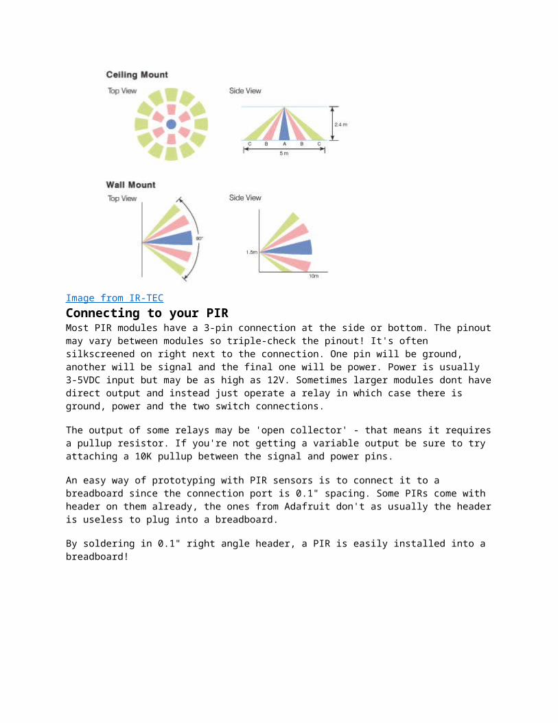
Images from NL11NH datasheetHere is another image, more qualitative but not as quantitative. (Note that the sensor in the Adafruit shop is 110° not 90°)

Image from IR-TEC
Connecting to your PIRMost PIR modules have a 3-pin connection at the side or bottom. The pinout may vary between modules so triple-check the pinout! It's often silkscreened on right next to the connection. One pin will be ground, another will be signal and the final one will be power. Power is usually 3-5VDC input but may be as high as 12V. Sometimes larger modules dont have direct output and instead just operate a relay in which case there is ground, power and the two switch connections.
The output of some relays may be 'open collector' - that means it requires a pullup resistor. If you're not getting a variable output be sure to try attaching a 10K pullup between the signal and power pins.
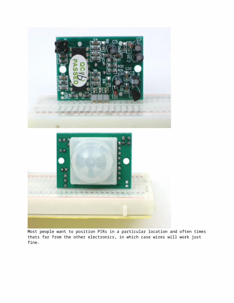
An easy way of prototyping with PIR sensors is to connect it to a breadboard since the connection port is 0.1" spacing. Some PIRs come with header on them already, the ones from Adafruit don't as usually the header is useless to plug into a breadboard.
By soldering in 0.1" right angle header, a PIR is easily installed into a breadboard!

Most people want to position PIRs in a particular location and often times thats far from the other electronics, in which case wires will work just fine.
Testing your PIROnce you have your PIR wired up its a good idea to do a simple test to verify that it works the way you expect. This test is also good for range testing. Simply connect 3-4 alkaline batteries (make sure you have more than 3.5VDC out but less than 6V by checking with your multimeter!) and connectground to the - pin on your PIR. Power goes to the + pin. Then connect a basic red LED (red LEDs have lower forward voltages than green or blue so they work better with only the 3.3v output) and a 220Ω resistor (any value from 100Ω to 1.0KΩ will do fine) to the out pin as shown. Of course, the LED and resistor can swap locations as long as the LED is oriented connection and connects between out and ground
Now when the PIR detects motion, the output pin will go "high" to 3.3V and light up the LED!
Once you have the breadboard wired up, insert batteries and wait 30-60 seconds for the PIR to 'stabilize'. During that time the LED may blink a little. Wait until the LED is off and then move around in front of it, waving a hand, etc, to see the LED light up!
Retriggering
Once you have the LED blinking, look on the back of the PIR sensor and make sure that the jumper is placed in the L position as shown above.

Now set up the testing board again. You may notice that when connecting up the PIR sensor as above, the LED does not stay on when moving in front of it but actually turns on and off every second or so. That is called "non-retriggering".
Now change the jumper so that it is in the H position. If you set up the test, you will notice that now the LED does stay on the entire time that something is moving. That is called "retriggering"
(The graphs above are from the BISS0001 datasheet, they kinda suck)
For most applications, "retriggering" (jumper in H position) mode is a little nicer. If you need to connect the sensor to something edge-triggered, you'll want to set it to "non-retriggering" (jumper in L position).
Changing pulse time and timeout lengthThere are two 'timeouts' associated with the PIR sensor. One is the "Tx" timeout: how long the LED is lit after it detects movement. The second is the "Ti" timeout which is how long the LED is guaranteed to be off when there is no movement. These are not easily changed but if you're handy with a soldering iron it is within reason.First, lets take a look at the BISS datasheet again

Determining R10 and R9 isnt too tough. Unfortunately this PIR sensor is mislabeled (it looks like they swapped R9 R17). You can trace the pins by looking at the BISS001 datasheet and figuring out what pins they are - R10 connects to pin 3 and R9 connects to pin 7. the capacitors are a little tougher to determine, but you can 'reverse engineer' them from timing the sensor and solving!
For the sensor in the Adafruit shop:
Tx is = 24576 * R10 * C6 = ~1.2 seconds R10 = 4.7K and C6 = 10nFLikewise,
Ti = 24 * R9 * C7 = ~1.2 seconds R9 = 470K and C7 = 0.1uFYou can change the timing by swapping different resistors or capacitors. For a nice tutorial on this, see Keith's PIR hacking page
Project examplesA simple room greeter that plays the super mario brothers theme music when triggered by a PIR in a hacked airwick freshener unit.

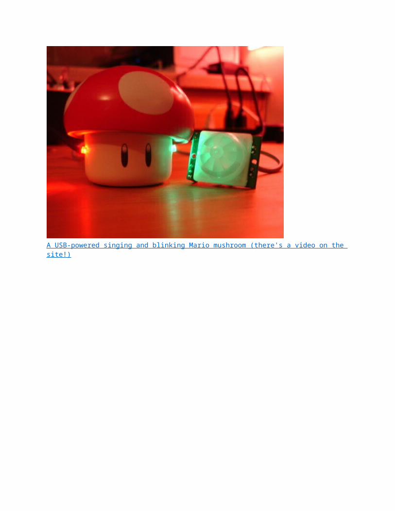
A USB-powered singing and blinking Mario mushroom (there's a video on the site!)

Rain Umbrellas Testing a PIR sensor for interfacing to Max/MSP for an interactive gardenA home-made security system using PIR sensors (which is built into a Start Trek panel!)

PIR sensor + Arduino + Servo = automatic cat door!
A 2-PIR motion tracker by Lucky Larry A PIR-based remote camera trigger (also by Lucky Larry!) An interesting hack whereby the PIR sensor is used 'raw' to track movement
Reading PIR sensorsConnecting PIR sensors to a microcontroller is really simple. The PIR acts as a digital output so all you need to do is listen for the pin to flip high (detected) or low (not detected).
Its likely that you'll want reriggering, so be sure to put the jumper in the H position!Power the PIR with 5V and connect ground to ground. Then connect the output to a digital pin. In this example we'll use pin 2.
The code is very simple, and is basically just keeps track of whether the input to pin 2 is high or low. It also tracks the state of the pin, so that it prints out a message when motion has started and stopped.
/* * PIR sensor tester */ int ledPin = 13; // choose the pin for the LEDint inputPin = 2; // choose the input pin (for PIR sensor)int pirState = LOW; // we start, assuming no motion detectedint val = 0; // variable for reading the pin status void setup() { pinMode(ledPin, OUTPUT); // declare LED as output pinMode(inputPin, INPUT); // declare sensor as input Serial.begin(9600);} void loop(){ val = digitalRead(inputPin); // read input value if (val == HIGH) { // check if the input is HIGH digitalWrite(ledPin, HIGH); // turn LED ON if (pirState == LOW) { // we have just turned on Serial.println("Motion detected!");

// We only want to print on the output change, not state pirState = HIGH; } } else { digitalWrite(ledPin, LOW); // turn LED OFF if (pirState == HIGH){ // we have just turned of Serial.println("Motion ended!"); // We only want to print on the output change, not state pirState = LOW; } }}
Don't forget that there are some times when you don't need a microcontroller. A PIR sensor can be connected to a relay (perhaps with a transistor buffer) without a micro!
This page was autogenerated from http://www.ladyada.net/wiki/tutorials/learn/sensors/pir.html Please edit the wiki to contribute any updates or corrections.


![Blue Line Gen2 Quad PIR Motion Detector (12 m [40 ft] …resource.boschsecurity.com/documents/Data_sheet_enUS_2603527307… · Intrusion Systems | Blue Line Gen2 Quad PIR Motion Detector](https://static.fdocuments.in/doc/165x107/5a7432f77f8b9a4b538bae2f/blue-line-gen2-quad-pir-motion-detector-12-m-40-ft-intrusion-systems.jpg)