PIR Motion Sensor - ElectronicWingsSun-07-16-02... · 2017-08-01 · Using a PIR Reading PIR...
30
PIR Motion Sensor Created by lady ada Last updated on 2016-02-25 02:32:58 PM EST
Transcript of PIR Motion Sensor - ElectronicWingsSun-07-16-02... · 2017-08-01 · Using a PIR Reading PIR...

PIR Motion SensorCreated by lady ada
Last updated on 2016-02-25 02:32:58 PM EST

235
779
1517172021222424
2630
Guide Contents
Guide ContentsOverview
Some Basic Stats
How PIRs WorkThe PIR SensorLenses
Connecting to a PIRTesting a PIRRetriggeringChanging sensitivityChanging Pulse Time and Timeout LengthFor older/other PIR sensorsUsing a PIR
Reading PIR Sensors
Example ProjectsBuy a PIR Motion Sensor
© Adafruit Industries https://learn.adafruit.com/pir-passive-infrared-proximity-motion-sensor
Page 2 of 30

OverviewPIR sensors allow you to sense motion, almost always used to detect whether a human has moved inor out of the sensors range. They are small, inexpensive, low-power, easy to use and don't wear out.For that reason they are commonly found in appliances and gadgets used in homes or businesses.They are often referred to as PIR, "Passive Infrared", "Pyroelectric", or "IR motion" sensors.
PIRs are basically made of a pyroelectric sensor (http://adafru.it/aKh) (which you can see above as theround metal can with a rectangular crystal in the center), which can detect levels of infrared radiation.Everything emits some low level radiation, and the hotter something is, the more radiation is emitted.The sensor in a motion detector is actually split in two halves. The reason for that is that we arelooking to detect motion (change) not average IR levels. The two halves are wired up so that theycancel each other out. If one half sees more or less IR radiation than the other, the output will swinghigh or low.
© Adafruit Industries https://learn.adafruit.com/pir-passive-infrared-proximity-motion-sensor
Page 3 of 30

Along with the pyroelectic sensor is a bunch of supporting circuitry, resistors and capacitors. It seemsthat most small hobbyist sensors use the BISS0001 ("Micro Power PIR Motion DetectorIC") (http://adafru.it/clR), undoubtedly a very inexpensive chip. This chip takes the output of the sensorand does some minor processing on it to emit a digital output pulse from the analog sensor.
Our older PIRs looked like this:
Our new PIRs have more adjustable settings and have a header installed in the 3-pinground/out/power pads
© Adafruit Industries https://learn.adafruit.com/pir-passive-infrared-proximity-motion-sensor
Page 4 of 30

For many basic projects or products that need to detect when a person has left or entered the area, orhas approached, PIR sensors are great. They are low power and low cost, pretty rugged, have a widelens range, and are easy to interface with. Note that PIRs won't tell you how many people are aroundor how close they are to the sensor, the lens is often fixed to a certain sweep and distance (although itcan be hacked somewhere) and they are also sometimes set off by housepets. Experimentation iskey!
Some Basic StatsThese stats are for the PIR sensor in the Adafruit shop which is very much like the Parallaxone (http://adafru.it/aKj) . Nearly all PIRs will have slightly different specifications, although they allpretty much work the same. If there's a datasheet, you'll want to refer to it
Size: RectangularPrice: $10.00 at the Adafruit shop (http://adafru.it/aIH)Output: Digital pulse high (3V) when triggered (motion detected) digital low when idle (nomotion detected). Pulse lengths are determined by resistors and capacitors on the PCB anddiffer from sensor to sensor.Sensitivity range: up to 20 feet (6 meters) 110° x 70° detection rangePower supply: 3V-9V input voltage, but 5V is ideal.
© Adafruit Industries https://learn.adafruit.com/pir-passive-infrared-proximity-motion-sensor
Page 5 of 30

BIS0001 Datasheet (http://adafru.it/clR) (the decoder chip used)RE200B datasheet (http://adafru.it/clS) (most likely the PIR sensing element used)NL11NH datasheet (http://adafru.it/clT) (equivalent lens used)Parallax Datasheet on their version of the sensor (http://adafru.it/clU)
More links!
A great page on PIR sensors from GLOLAB \\ (http://adafru.it/aKn)
© Adafruit Industries https://learn.adafruit.com/pir-passive-infrared-proximity-motion-sensor
Page 6 of 30

How PIRs WorkPIR sensors are more complicated than many of the other sensors explained in these tutorials (likephotocells, FSRs and tilt switches) because there are multiple variables that affect the sensors inputand output. To begin explaining how a basic sensor works, we'll use this rather nice diagram (ifanyone knows where it originates plz let me know).
The PIR sensor itself has two slots in it, each slot is made of a special material that is sensitive to IR.The lens used here is not really doing much and so we see that the two slots can 'see' out past somedistance (basically the sensitivity of the sensor). When the sensor is idle, both slots detect the sameamount of IR, the ambient amount radiated from the room or walls or outdoors. When a warm bodylike a human or animal passes by, it first intercepts one half of the PIR sensor, which causes a positivedifferential change between the two halves. When the warm body leaves the sensing area, the reversehappens, whereby the sensor generates a negative differential change. These change pulses arewhat is detected.
The PIR SensorThe IR sensor itself is housed in a hermetically sealed metal can to improvenoise/temperature/humidity immunity. There is a window made of IR-transmissive material (typicallycoated silicon since that is very easy to come by) that protects the sensing element. Behind the
© Adafruit Industries https://learn.adafruit.com/pir-passive-infrared-proximity-motion-sensor
Page 7 of 30

window are the two balanced sensors.
Left image from Murata datasheet (http://adafru.it/cm5)
Image from RE200B datasheet (http://adafru.it/clS)
You can see above the diagram showing the element window, the two pieces of sensing material
Image from RE200B datasheet (http://adafru.it/clS)
This image shows the internal schematic. There is actually a JFET inside (a type of transistor) which isvery low-noise and buffers the extremely high impedence of the sensors into something a low-costchip (like the BIS0001) can sense.
© Adafruit Industries https://learn.adafruit.com/pir-passive-infrared-proximity-motion-sensor
Page 8 of 30

LensesPIR sensors are rather generic and for the most part vary only in price and sensitivity. Most of the realmagic happens with the optics. This is a pretty good idea for manufacturing: the PIR sensor andcircuitry is fixed and costs a few dollars. The lens costs only a few cents and can change the breadth,range, sensing pattern, very easily.In the diagram up top, the lens is just a piece of plastic, but that means that the detection area is justtwo rectangles. Usually we'd like to have a detection area that is much larger. To do that, we use asimple lens (http://adafru.it/aKq) such as those found in a camera: they condenses a large area (suchas a landscape) into a small one (on film or a CCD sensor). For reasons that will be apparent soon,we would like to make the PIR lenses small and thin and moldable from cheap plastic, even though itmay add distortion. For this reason the sensors are actually Fresnel lenses (http://adafru.it/aKr):
Image from Sensors Magazine (http://adafru.it/aKs)
The Fresnel lens condenses light, providing a larger range of IR to the sensor.
Image from BHlens.com (http://adafru.it/aKt)
© Adafruit Industries https://learn.adafruit.com/pir-passive-infrared-proximity-motion-sensor
Page 9 of 30

Image from Cypress appnote 2105 (http://adafru.it/cm6)
OK, so now we have a much larger range. However, remember that we actually have two sensors,and more importantly we dont want two really big sensing-area rectangles, but rather a scattering ofmultiple small areas. So what we do is split up the lens into multiple section, each section of which is afresnel lens.
© Adafruit Industries https://learn.adafruit.com/pir-passive-infrared-proximity-motion-sensor
Page 10 of 30
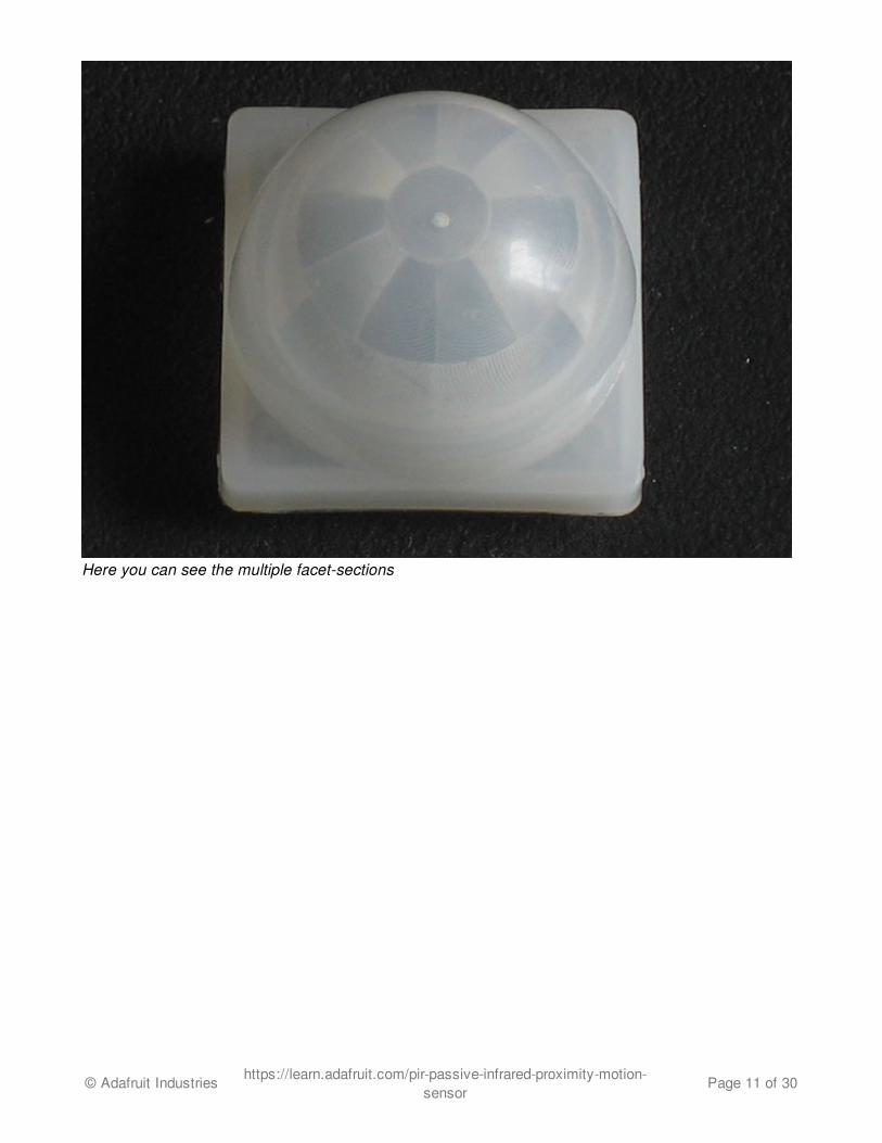
Here you can see the multiple facet-sections
© Adafruit Industries https://learn.adafruit.com/pir-passive-infrared-proximity-motion-sensor
Page 11 of 30

This macro shot shows the different Frenel lenses in each facet!
The different faceting and sub-lenses create a range of detection areas, interleaved with each other.Thats why the lens centers in the facets above are 'inconsistant' - every other one points to a differenthalf of the PIR sensing element
© Adafruit Industries https://learn.adafruit.com/pir-passive-infrared-proximity-motion-sensor
Page 12 of 30
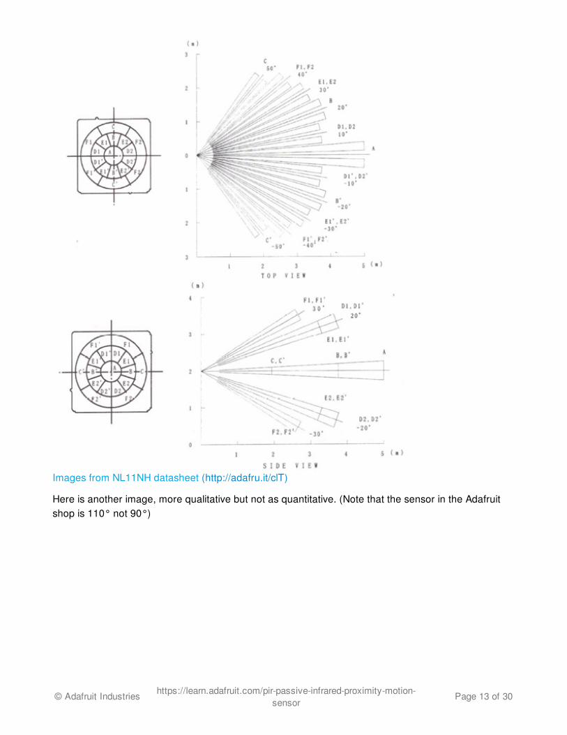
Images from NL11NH datasheet (http://adafru.it/clT)
Here is another image, more qualitative but not as quantitative. (Note that the sensor in the Adafruitshop is 110° not 90°)
© Adafruit Industries https://learn.adafruit.com/pir-passive-infrared-proximity-motion-sensor
Page 13 of 30

Image from IR-TEC (http://adafru.it/aKv)
© Adafruit Industries https://learn.adafruit.com/pir-passive-infrared-proximity-motion-sensor
Page 14 of 30

Connecting to a PIR
Most PIR modules have a 3-pin connection at the side or bottom. The pinout may vary betweenmodules so triple-check the pinout! It's often silkscreened on right next to the connection (at least,ours is!) One pin will be ground, another will be signal and the final one will be power. Power is usually3-5VDC input but may be as high as 12V. Sometimes larger modules don't have direct output andinstead just operate a relay in which case there is ground, power and the two switch connections.
The output of some relays may be 'open collector' - that means it requires a pullup resistor. If you'renot getting a variable output be sure to try attaching a 10K pullup between the signal and power pins.
An easy way of prototyping with PIR sensors is to connect it to a breadboard since the connection portis 0.1" spacing. Some PIRs come with header on them already, the one's from adafruit have a straight3-pin header on them for connecting a cable
© Adafruit Industries https://learn.adafruit.com/pir-passive-infrared-proximity-motion-sensor
Page 15 of 30
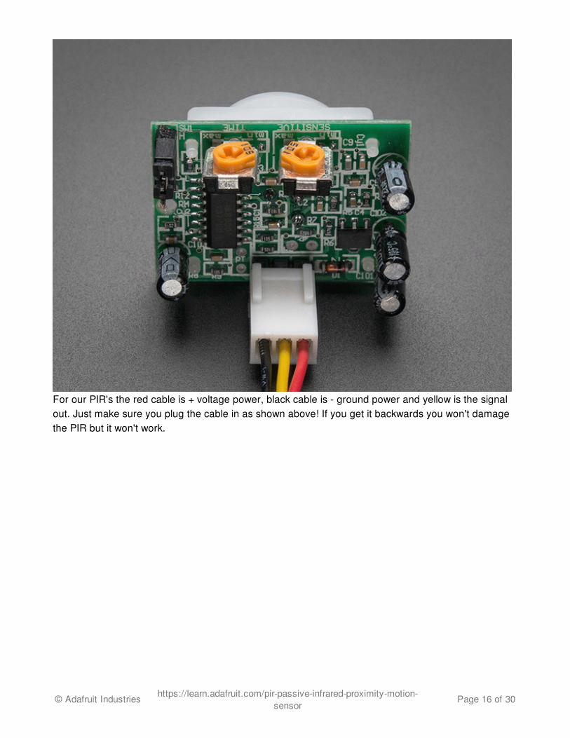
For our PIR's the red cable is + voltage power, black cable is - ground power and yellow is the signalout. Just make sure you plug the cable in as shown above! If you get it backwards you won't damagethe PIR but it won't work.
© Adafruit Industries https://learn.adafruit.com/pir-passive-infrared-proximity-motion-sensor
Page 16 of 30

Testing a PIR
Now when the PIR detects motion, the output pin will go "high" to 3.3V and light up the LED!
Once you have the breadboard wired up, insert batteries and wait 30-60 seconds for the PIR to'stabilize'. During that time the LED may blink a little. Wait until the LED is off and then move around infront of it, waving a hand, etc, to see the LED light up!
Retriggering
© Adafruit Industries https://learn.adafruit.com/pir-passive-infrared-proximity-motion-sensor
Page 17 of 30

There's a couple options you may have with your PIR. First up we'll explore the 'Retriggering' option.
Once you have the LED blinking, look on the back of the PIR sensor and make sure that the jumper isplaced in the L position as shown below.
© Adafruit Industries https://learn.adafruit.com/pir-passive-infrared-proximity-motion-sensor
Page 18 of 30
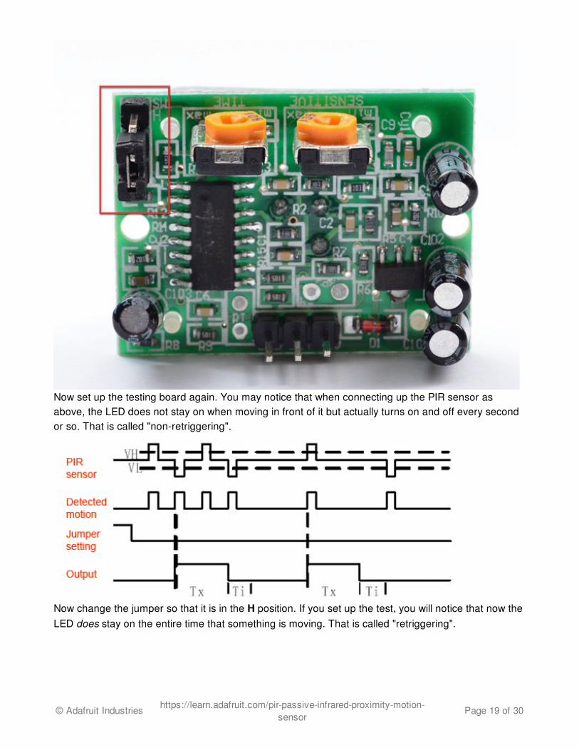
Now set up the testing board again. You may notice that when connecting up the PIR sensor asabove, the LED does not stay on when moving in front of it but actually turns on and off every secondor so. That is called "non-retriggering".
Now change the jumper so that it is in the H position. If you set up the test, you will notice that now theLED does stay on the entire time that something is moving. That is called "retriggering".
© Adafruit Industries https://learn.adafruit.com/pir-passive-infrared-proximity-motion-sensor
Page 19 of 30
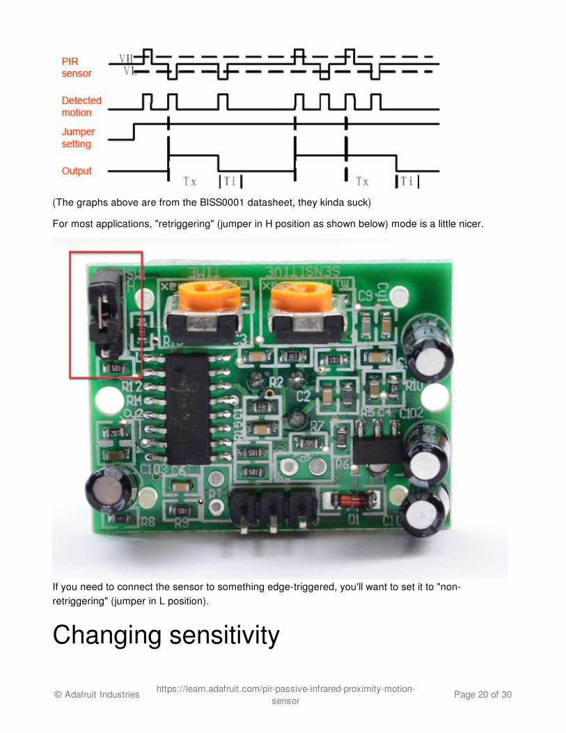
(The graphs above are from the BISS0001 datasheet, they kinda suck)
For most applications, "retriggering" (jumper in H position as shown below) mode is a little nicer.
If you need to connect the sensor to something edge-triggered, you'll want to set it to "non-retriggering" (jumper in L position).
Changing sensitivity
© Adafruit Industries https://learn.adafruit.com/pir-passive-infrared-proximity-motion-sensor
Page 20 of 30

The Adafruit PIR has a trimpot on the back for adjusting sensitivity. You can adjust this if your PIR istoo sensitive or not sensitive enough - clockwise makes it more sensitive.
Changing Pulse Time and TimeoutLengthThere are two 'timeouts' associated with the PIR sensor. One is the "Tx" timeout: how long the LED islit after it detects movement - this is easy to adjust on Adafruit PIR's because there's a potentiometer.
The second is the "Ti" timeout which is how long the LED is guaranteed to be off when there is nomovement. This one is not easily changed but if you're handy with a soldering iron it is within reason.First, lets take a look at the BISS datasheet again
© Adafruit Industries https://learn.adafruit.com/pir-passive-infrared-proximity-motion-sensor
Page 21 of 30

On Adafruit PIR sensors, there's a little trim potentiometer labeled TIME. This is a 1 Megaohmadjustable resistor which is added to a 10K series resistor. And C6 is 0.01uF so
Tx = 24576 x (10K + Rtime) x 0.01uF
If the Rtime potentiometer is turned all the way down counter-clockwise (to 0 ohms) then
Tx = 24576 x (10K) x 0.01uF = 2.5 seconds (approx)
If the Rtime potentiometer is turned all the way up clockwise to 1 Megaohm then
Tx = 24576 x (1010K) x 0.01uF = 250 seconds (approx)
If RTime is in the middle, that'd be about 120 seconds (two minutes) so you can tweak it as necessary.For example if you want motion from someone to turn on a fan for a minimum of 1 minute, set theRtime potentiometer to about 1/4 the way around.
For older/other PIR sensorsIf you have a PIR sensor from somewhere else that does not have a potentiometer adjust, you cantrace out the adjustment resistors this way:
© Adafruit Industries https://learn.adafruit.com/pir-passive-infrared-proximity-motion-sensor
Page 22 of 30
Determining R10 and R9 isnt too tough. Unfortunately this PIR sensor is mislabeled (it looks like theyswapped R9 R17). You can trace the pins by looking at the BISS001 datasheet and figuring out whatpins they are - R10 connects to pin 3 and R9 connects to pin 7. the capacitors are a little tougher todetermine, but you can 'reverse engineer' them from timing the sensor and solving!
For example:
Tx is = 24576 * R10 * C6 = ~1.2 seconds R10 = 4.7K and C6 = 10nF
Likewise,
Ti = 24 * R9 * C7 = ~1.2 seconds R9 = 470K and C7 = 0.1uF
You can change the timing by swapping different resistors or capacitors. For a nice tutorial on this, seeKeith's PIR hacking page (http://adafru.it/aKw).
© Adafruit Industries https://learn.adafruit.com/pir-passive-infrared-proximity-motion-sensor
Page 23 of 30

Using a PIRReading PIR SensorsConnecting PIR sensors to a microcontroller is really simple. The PIR acts as a digital output so all youneed to do is listen for the pin to flip high (detected) or low (not detected).Its likely that you'll want reriggering, so be sure to put the jumper in the H position!
Power the PIR with 5V and connect ground to ground. Then connect the output to a digital pin. In thisexample we'll use pin 2.
The code is very simple, and is basically just keeps track of whether the input to pin 2 is high or low. Italso tracks the state of the pin, so that it prints out a message when motion has started and stopped.
/* * PIR sensor tester */ int ledPin = 13; // choose the pin for the LEDint inputPin = 2; // choose the input pin (for PIR sensor)int pirState = LOW; // we start, assuming no motion detectedint val = 0; // variable for reading the pin status void setup() { pinMode(ledPin, OUTPUT); // declare LED as output pinMode(inputPin, INPUT); // declare sensor as input
© Adafruit Industries https://learn.adafruit.com/pir-passive-infrared-proximity-motion-sensor
Page 24 of 30

Serial.begin(9600);} void loop(){ val = digitalRead(inputPin); // read input value if (val == HIGH) { // check if the input is HIGH digitalWrite(ledPin, HIGH); // turn LED ON if (pirState == LOW) { // we have just turned on Serial.println("Motion detected!"); // We only want to print on the output change, not state pirState = HIGH; } } else { digitalWrite(ledPin, LOW); // turn LED OFF if (pirState == HIGH){ // we have just turned of Serial.println("Motion ended!"); // We only want to print on the output change, not state pirState = LOW; } }}
Don't forget that there are some times when you don't need a microcontroller. A PIR sensor can beconnected to a relay (perhaps with a transistor buffer) without a micro!
© Adafruit Industries https://learn.adafruit.com/pir-passive-infrared-proximity-motion-sensor
Page 25 of 30

Example ProjectsA simple room greeter that plays the super mario brothers theme music when triggered by a PIR in ahacked airwick freshener unit.
A USB-powered singing and blinking Mario mushroom (there's a video on thesite!) (http://adafru.it/aKx)
© Adafruit Industries https://learn.adafruit.com/pir-passive-infrared-proximity-motion-sensor
Page 26 of 30

Rain Umbrellas (http://adafru.it/aKy)A home-made security system using PIR sensors (which is built into a Start Trek panel!)PIR sensor + Arduino + Servo = automatic cat door!
© Adafruit Industries https://learn.adafruit.com/pir-passive-infrared-proximity-motion-sensor
Page 27 of 30

A 2-PIR motion tracker (http://adafru.it/aKz) by Lucky Larry
© Adafruit Industries https://learn.adafruit.com/pir-passive-infrared-proximity-motion-sensor
Page 28 of 30

A PIR-based remote camera trigger (also by Lucky Larry!) (http://adafru.it/aKA)An interesting hack whereby the PIR sensor is used 'raw' to track movement.
© Adafruit Industries https://learn.adafruit.com/pir-passive-infrared-proximity-motion-sensor
Page 29 of 30

Buy a PIR Motion SensorBuy a PIR Motion Sensor (http://adafru.it/189)
© Adafruit Industries Last Updated: 2016-02-25 02:32:59 PM EST Page 30 of 30