
Piping System Failure Report_ISE
16
Pipe System Failure Report Phase III of the Hot and Chilled Water Lines Tunnel Project # 528A8-10-814 Samuel S. Stratton VA Medical Center 113 Holland Avenue Albany, NY 12208 February 17, 2015 2359 Route 300 Wallkill, NY 12589 Phone: (845) 863-1788 Fax: (845) 863-1789
-
Upload
charlie-eadie -
Category
Documents
-
view
62 -
download
4
Transcript of Piping System Failure Report_ISE

Pipe System Failure Report Phase III of the Hot and Chilled Water Lines Tunnel
Project # 528A8-10-814
Samuel S. Stratton VA Medical Center
113 Holland Avenue
Albany, NY 12208
February 17, 2015
2359 Route 300
Wallkill, NY 12589
Phone: (845) 863-1788 Fax: (845) 863-1789

Table of Contents
1. PURPOSE .................................................................................................................................. 1
2. EXECUTIVE SUMMARY .............................................................................................................. 1
3. TIMELINE .................................................................................................................................. 2
4. BACKGROUND .......................................................................................................................... 3
5. SYSTEM FAILURE ....................................................................................................................... 8
6. DISCUSSION ............................................................................................................................ 12
7. CONCLUSION .......................................................................................................................... 14

Samuel S. Stratton VA Medical Center
Pipe System Failure Report
Phase III of Hot and Chilled Water Lines Tunnel 1
1. Purpose
The purpose of this report is to present the facts leading to the piping system failure on 11/13/2014.
2. Executive Summary
The hot water pipe system failed on 13 November 2014 because the design did not include proper anchoring. Iron Sword repeatedly communicated concern about this design shortfall. Nonetheless, after repeat affirmations from the engineer of record and direction from the VA, Iron Sword installed the pipe system as shown in the design documents. The specifications require that Iron Sword test the system. The test procedures followed the specifications in the contract and complied with standard industry practice. Applying pressure to the unrestrained expansion joints caused them to extend which caused more movement than the design anticipated. The additional movement damaged a number of components in the system to include the pipe (torn), pipe guides, rollers and expansion joints. The damage caused by this design flaw is unfortunate. Iron Sword has continually strived to deliver this project and advise the VA on the best course of action to achieve that end. In spite of the setbacks associated with the piping system failure, Iron Sword remains focused on the mission of delivering a complete Hot and Chilled Water Line Tunnel system to the VA Medical Center. We have continued to work as a team player to try to resolve all issues. We look forward to completing the project in the coming months. In keeping with the spirit of working towards resolution, and acting at your request, we submit this report. This report will cover the background of the communications, decisions, events and facts leading up to the hot water pipe system failure. First, the report will show a timeline of events followed by a narrative. Next, the report will include details of the events during the day of the system failure. The report will include a discussion of these events and our conclusions. If you have any questions or concerns after reading this report, please do not hesitate to contact Charlie Eadie via email at [email protected] or via phone at (845) 419-3760.
Respectfully submitted,
Charlie Eadie Greg Louks Vice President President & CEO
Attachments:
1. 12-0517 RFI 043 Response – Piping Pressure Test 2. 13-0722 RFI 002 Response – Anchor Locks 3. 13-0722 RFI 004 Response – Design and Function 4. PDF Graphic, “Unrestrained Extension in Piping System”
C.Eadie
Snapshot
Samuel S. Stratton VA Medical Center
Pipe System Failure Report
Phase III of Hot and Chilled Water Lines Tunnel 2
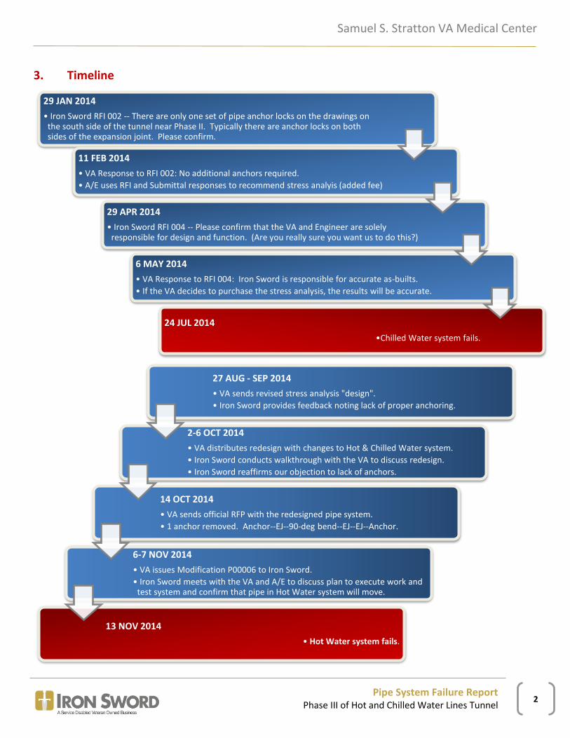
3. Timeline
29 JAN 2014
• Iron Sword RFI 002 -- There are only one set of pipe anchor locks on the drawings on the south side of the tunnel near Phase II. Typically there are anchor locks on both sides of the expansion joint. Please confirm.
11 FEB 2014
• VA Response to RFI 002: No additional anchors required.
• A/E uses RFI and Submittal responses to recommend stress analyis (added fee)
29 APR 2014
• Iron Sword RFI 004 -- Please confirm that the VA and Engineer are solely responsible for design and function. (Are you really sure you want us to do this?)
6 MAY 2014
• VA Response to RFI 004: Iron Sword is responsible for accurate as-builts.
• If the VA decides to purchase the stress analysis, the results will be accurate.
24 JUL 2014
•Chilled Water system fails.
27 AUG - SEP 2014
• VA sends revised stress analysis "design".
• Iron Sword provides feedback noting lack of proper anchoring.
2-6 OCT 2014
• VA distributes redesign with changes to Hot & Chilled Water system.
• Iron Sword conducts walkthrough with the VA to discuss redesign.
• Iron Sword reaffirms our objection to lack of anchors.
14 OCT 2014
• VA sends official RFP with the redesigned pipe system.
• 1 anchor removed. Anchor--EJ--90-deg bend--EJ--EJ--Anchor.
6-7 NOV 2014
• VA issues Modification P00006 to Iron Sword.
• Iron Sword meets with the VA and A/E to discuss plan to execute work and test system and confirm that pipe in Hot Water system will move.
13 NOV 2014
• Hot Water system fails.

Samuel S. Stratton VA Medical Center
Pipe System Failure Report
Phase III of Hot and Chilled Water Lines Tunnel 3
4. Background
Iron Sword initially raised concerns about the anchors in the Hot and Chilled Water Lines project during the first phase of the project. During the “Phase II” portion of the project, we submitted RFI 043 with the following text:
In regards to hydro-static testing of the new ‘Hot Water and Chilled Water’ piping in the new tunnel, we have some concerns…We advise not pressurizing the lines any further due to the fact that there are no permanent anchors on either side of the last expansion [joint] before the weld caps that end our project…We also question the fact that even after the [next] phase is complete, there are no anchors near these expansion joints.1
We continued to express this concern during Phase III of the project. We submitted RFI 002 in January 2014 to ask about the recognizable lack of necessary anchor locks in the design and recommend that the VA add the appropriate anchors. We based our concern upon industry guidelines and manufacturer installation instructions, which the specifications direct us to follow. Specification Section 23 21 13 Hydronic Piping includes the ASME B31.1-08 Power Piping Code by reference. The specification outlines that bellows—externally pressurized type—conform to the standards of EJMA (Expansion Joint Manufacturers Association) and ASME B31.1. The ASME code states,
Where corrugated or slip-type expansion joints, or flexible metal hose assemblies are used anchors and guides shall be provided where necessary to direct the expansion into the joint or hose assembly. Such anchors shall be designed to withstand the force specified by the manufacturer for the design conditions at which the joint or hose assembly is to be used. If this force is otherwise unknown, it shall be taken as the sum of the product of the maximum internal area times the design pressure plus the force required to deflect the joint or hose assembly.2
The Hydronic Piping specification also includes the following language, “Anchors and Guides: Provide type, quantity and spacing as recommended by manufacturer of expansion joint and as shown”. Each phase of this project has a different expansion joint, but both outline the need to properly anchor and guide the expansion joints.
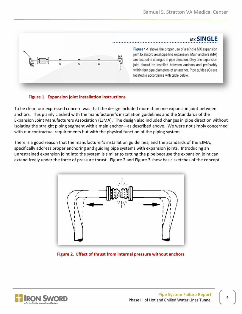
The Microflex Installation Instructions, shown below in Figure 1, explain that the MX externally pressurized expansion joints “are designed to absorb axial movement only, and must therefore be installed in straight sections of pipelines, with properly designed anchors, guides, and supports”. The instructions continue; “main anchors (MA) are located at changes in pipe direction. Only one expansion joint should be installed between anchors and preferably within four pipe diameters of an anchor”.
1 See attached RFI 043, submitted 3/21/14 and returned 5/8/14. 2 ASME B31.1.121.7.1 Anchors and Guides paragraph (c)
Samuel S. Stratton VA Medical Center
Pipe System Failure Report
Phase III of Hot and Chilled Water Lines Tunnel 4
Figure 1. Expansion joint installation instructions
To be clear, our expressed concern was that the design included more than one expansion joint between anchors. This plainly clashed with the manufacturer’s installation guidelines and the Standards of the Expansion Joint Manufacturers Association (EJMA). The design also included changes in pipe direction without isolating the straight piping segment with a main anchor—as described above. We were not simply concerned with our contractual requirements but with the physical function of the piping system.
There is a good reason that the manufacturer’s installation guidelines, and the Standards of the EJMA, specifically address proper anchoring and guiding pipe systems with expansion joints. Introducing an unrestrained expansion joint into the system is similar to cutting the pipe because the expansion joint can extend freely under the force of pressure thrust. Figure 2 and Figure 3 show basic sketches of the concept.
Figure 2. Effect of thrust from internal pressure without anchors

Samuel S. Stratton VA Medical Center
Pipe System Failure Report
Phase III of Hot and Chilled Water Lines Tunnel 5
Figure 3. Illustrating pressure thrust
The Standards of the Expansion Joint Manufacturers Association (EJMA) includes an example of the load considerations for a flange connection with an expansion joint. The explanation outlines the force that acts on the flange connection due to thrust loading shown in Figure 4, “when an unrestrained expansion joint is employed as shown in Figure C13.2 [Figure 5], the flange loading conditions change dramatically. In order to keep the expansion joint from freely extending, a main anchor is normally utilized to restrain the elbow. This main anchor will also carry the pressure thrust that results from the pressurization of the system and release this load from the flange bolts”.3
Figure 4. Force due to axial loading
3 Section C / Page 100, Standards of the Expansion Joint Manufacturers Association, Inc.

Samuel S. Stratton VA Medical Center
Pipe System Failure Report
Phase III of Hot and Chilled Water Lines Tunnel 6
Figure 5. Main anchor restrains expansion joint
The design did not adhere to any expansion joint manufacturer’s standard for anchoring, and the physical implications of allowing expansion joints to expand freely were clear to Iron Sword, but the VA maintained the position that no additional anchors were necessary. After we recommended adding anchors as part of our question in RFI 002, the VA responded, dated 2/27/14, and included the A/E response (emphasis added):
During the Phase III Pre-Construction Review Meeting, a comment from VA personnel instructed FFA [Friedman Fisher Associates] to add an additional expansion joint in the straight horizontal run of pipe prior to where the pipe turns and enters the Warehouse. The structural pipe analysis, that was current at the time, did not call for any additional expansion joints or anchors in this section. We added the expansion joint to the piping drawing without additional analysis, with the opinion that additional flexibility would not be an issue.
Answer: Although adding expansion joints for additional flexibility in a piping system may not be an issue, it has been our experience that adding too many anchors and over-restraining certain piping systems can be detrimental to the overall flexibility of the system. We do not recommend adding additional restraints without additional services to modify and re-run the pipe stress analysis.4
This RFI response provides a number of important facts and observations. First, the engineer added an expansion joint to the piping system without conducting an additional analysis. It seems to reason that the analysis to which he refers would be a “stress analysis” otherwise known as calculating the forces and moments acting upon the system during the most severe conditions (temperature, pressure, etc.) and verifying that the system design accommodates such stresses (per the ASME code). Second, the engineer expressed justification for this lack of analysis based upon “the opinion that additional flexibility would not be an issue”. Third, the engineer recommended against adding additional restraints. Fourth, the
4 See attached response to RFI 002, dated 2/27/14 from VA and 2/25/14 from Pete Black and Paul Lawton of Friedman Fisher Assoc.

Samuel S. Stratton VA Medical Center
Pipe System Failure Report
Phase III of Hot and Chilled Water Lines Tunnel 7
engineer qualified his professional opinion (recommendation) by advocating that the client pay him to modify and re-run the pipe stress analysis.
In response to Iron Sword’s Hydronic Piping Shop Drawing submittal, the engineer5 recommended that an additional stress analysis be performed for record as an as built. The VA returned the submittal to Iron Sword as “Approved as Noted” and “No deviated noted; None Approved”, with the comment that, “VA emphasizes that accurate as-built drawings must be maintained, so that if the recommended final stress analysis is purchase from the AE, the results will be accurate”.6 Based on the comments included in the submittal response, and to ensure that we understood the VA direction, Iron Sword submitted RFI 004 on 4/29/14 requesting confirmation that the “VA and Engineer are responsible for the design and function of the system”. The VA responded on 5/14/14 by stating that Iron Sword’s sole responsibility relating to the notes regarding stress analysis was to maintain accurate as built drawings.7
The next event of significance to this report was the failure of the chilled water system on 7/24/14. The unrestrained expansion joints extended and the pipe expanded causing damage. This started the process of redesigning the system in motion. The VA acquired an additional stress analysis from the engineer. Iron Sword provided as built drawings to enable the stress analysis and the engineer visited the site to field verify. The VA distributed the “as built mods” drawings and Iron Sword coordinated a walkthrough to discuss the system changes. Iron Sword stressed the importance of proper anchoring, but the modifications did not comport with the EJMA recommendations. The VA issued an RFP on 10/14/14, which included changes to both the Hot and Chilled Water piping systems. Iron Sword submitted a proposal on 10/20/14 with a statement warning the VA that the design did not comply with recommendations for anchors noted in the manufacturer’s installation guidelines (included as attachment). The VA issued contract modification P00006 on 11/6/14.
The modification included removing the weld between the base of the anchor and the stanchion at point A44 of the hot water system. The “drawing” called for Iron Sword to install metal plate stops 1 inch from either side of the support base as shown on Figure 6. The modification included a detail for these plates. Iron Sword executed the change as directed by the modification, drawings and specifications. On 11/7/14, Iron Sword—represented by Charlie Eadie (Vice President) and Pete Burger (Superintendent)—met with the VA Engineering Manager, Oscar Prue, in his office to participate in a conference call with the A/E. During this discussion, Iron Sword communicated its intention to proceed with work until ready for a pressure test and then request another confirmation. The engineer maintained that the design was sound and that Iron Sword should proceed with the work as depicted. The engineer also confirmed that the pipe would move at point A44 and asserted that this would not be a problem. The VA directed Iron Sword to proceed with work. Iron Sword agreed to proceed accepting that the A/E bore responsibility for the design of the system.
5 Paul Lawton of Friedman Fisher Associates. 6 VA response to submittal number 23 21 13 – 003 R0, dated 4/24/14 (attached) 7 See attached response to RFI 004, dated 5/14/14 from the VA.

Samuel S. Stratton VA Medical Center
Pipe System Failure Report
Phase III of Hot and Chilled Water Lines Tunnel 8
Figure 6. Anchor removed during modification P0006
5. System Failure
On 11/13/14, Iron Sword supervised the pre-test of the hot water piping system. The following is the report given by Iron Sword’s superintendent, Pete Burger, immediately following the system failure.
Fill and pressurization procedures- 11/13/2014
As part of normal protocol our mechanical contractor intended to fill the piping to test pressure
today, and given all of the specified alterations to the HW piping had been completed and the
urgency that the VA voiced concerning completion of these repairs I proceeded. My intention was,
as is standard procedure in a witnessed pressure test, to inform the VA once the agreed upon test
pressure of 140# was reached. That the specified alterations were performed according to the

Samuel S. Stratton VA Medical Center
Pipe System Failure Report
Phase III of Hot and Chilled Water Lines Tunnel 9
proposal is indisputable; everything is in place as we were instructed and the failure occurred
precisely as we repeatedly cautioned that we suspected it would.
Thompkins’ workers, Kevin Teal Jr. and Dave Madsen, arrived on site @ 7:00 AM to continue
welding pipe anchors on CW lines at Warehouse end of tunnel and started filling HW piping
utilizing a ¾” hose connected to an outside hose bib on the chiller plant building and attached to
the HW piping at a connection with a shut off valve and pressure gauge located at the low point
of the tunnel piping at the Chiller Plant end of the tunnel. An electric pump was installed in the
hose line at the point of connection to the HW piping. I (Peter Burger) was also present for this
work.
At approximately 7:30 AM upon reaching 30 PSI the piping had moved against the stops that we
had been directed to install 1” away from the anchor and roller bases. As we had been told by the
engineer at the phone meeting held in Oscar’s office the week before that this should be expected,
and were reassured that they were confident in the design, we proceeded with the pressurization
process. At approximately 8:00 AM @100# of pressure, the anchor at the bend in the tunnel failed
when expansion compensators to either side of the bend extended allowing the upper HW pipe to
push into the corner towards the tunnel wall tearing away from the anchor. At this point, the “fill
to test pressure” process was stopped and the VA was notified of the failure of design.
As I said, we have repeatedly voiced our concerns regarding the design of piping anchor locations
and their relation to expansion compensators, and have been repeatedly rebuffed by the A/E. We
most recently requested “one last” meeting with the concerned parties and the A/E after being
asked (in light of the recent discovery of an underground leak) to proceed with getting this work
completed just as quickly as possible. We were once again assured that the design would work by
the A/E, and instructed to proceed as directed by the VA and assured that, should it fail, the A/E would
bear sole responsibility.

Samuel S. Stratton VA Medical Center
Pipe System Failure Report
Phase III of Hot and Chilled Water Lines Tunnel 10
Figure 7. Sliding anchor moves to 1-inch plate stops
Figure 8. Sliding roller support moves to 1-inch plate stops

Samuel S. Stratton VA Medical Center
Pipe System Failure Report
Phase III of Hot and Chilled Water Lines Tunnel 11
Figure 9. Pipe expands into the bend and forces act laterally on guides
Figure 10. Anchor at A44 (now sliding guide)

Samuel S. Stratton VA Medical Center
Pipe System Failure Report
Phase III of Hot and Chilled Water Lines Tunnel 12
Figure 11. Expansion joint extended beyond rated extension
The results of this pre-test were unfortunate. The events that followed this are all relatively well known and should not be a matter of debate. Iron Sword met with the director of the VA Medical Center along with the VA Projects and Facilities staff and the A/E. In the ensuing meetings, the engineer discussed the stress analysis program that he used to conduct the stress analysis—the results of which he used to design the system. In this discussion, the engineer described the model’s inability to account for the 1-inch metal plate stops that he added to the design. The error in modelling resulted in design parameters—including anticipated pipe movement—that were not accurate.
6. Discussion
The facts are present and the logical conclusion is clear: the design was flawed and this is the root cause of the system failure. Nonetheless, in spite of this readily apparent conclusion, some parties have insisted upon searching for ways to assign fault to Iron Sword. The most common items that have come up in discussion are the following:
1. Iron Sword did not execute test procedures correctly. Iron Sword needed VA and/or A/E present. 2. Iron Sword did not hire a PE to verify that the anchors and guides are properly designed. 3. Iron Sword did not provide adequate information on anchors.

Samuel S. Stratton VA Medical Center
Pipe System Failure Report
Phase III of Hot and Chilled Water Lines Tunnel 13
The first concern about Iron Sword pressurizing the pipe system is misguided. The chief complaint voiced by members of the VA projects team was that Iron Sword did not have the COR and A/E present when we began filling the pipe with water in preparation for a test. While the specifications require us to do leak testing to the satisfaction of the Resident Engineer, and require that an authorized representative of the Contracting Officer be present for the final test, there is no requirement to have anyone present for pre-tests, which the specification requires. In fact, specification section 01 00 00 General Requirements, Section 1.24 Tests, Paragraph A states, “Final test will not be conducted unless pre-tested”. On the day that the pipe system failed, the mechanical subcontractor filled the pipe with water and gradually brought it up to pressure in preparation for the final test. In keeping with the specification and industry standard practice, the plan was to achieve test pressure (pre-test) and then request that the VA provide an authorized representative to observe the final test. The specifications do not support the opinion that the COR and A/E needed to be present for the entire process. Finally, the VA and A/E directed Iron Sword to proceed during the meeting on 11/7/14. Iron Sword presented the idea of a final check to confirm we should test, to which the A/E said: not necessary.
The second concern about Iron Sword hiring a PE is unconvincing. The specification section 23 21 13 Hydronic Piping, Section 3.3 Expansion Joints (Bellows and Slip Type), Paragraph A, states: “Anchors and Guides: Provide type, quantity and spacing as recommended by manufacturer of expansion joint and as shown. A professional engineer shall verify in writing that anchors and guides are properly designed for forces and moments which will be imposed”. The projects staff has asked if we had hired a professional engineer. The short answer is no. The fact that Iron Sword did not hire a PE has no bearing on the system failure. As discussed, Iron Sword identified an issue with the first sentence of this requirement. We repeatedly informed the VA of our concern that the design lacked the requisite number of anchors. We read the installation guidelines, reviewed the drawing, and arrived at the simple fact that we could not provide anchors and guides of “quantity and spacing as recommended by manufacturer of expansion joint” because the design did not include the correct number of anchors. It does not take a professional engineer to read English and count the number of anchors on a drawing. We identified this fact in RFI 043 (Phase II), RFIs 002 & 004 (Phase III) and in numerous meetings, emails and phone calls.
The third and final issue that has come up in discussion is that Iron Sword did not provide enough information on the anchors installed. To the contrary, the fact is that the engineer did not provide a detail for the anchors in the design. Iron Sword has since provided a detail showing the dimensions of the anchors that we fabricated in the field, which we based on the limited information sent. While this line of questioning would serve the engineer when designing the system—in order to identify the anchors necessary to accommodate the forces—it presents no probative value in this assessing this system failure. None of the anchors failed.
Brad Fisher (Principal, FFA) stated that the stress analysis was flawed and that we installed the system in accordance with his design. Brad Fisher attributes the flawed design to a failure in the stress analysis software. This design did not properly anchor and guide the expansion joints in the system. We proceeded with the modifications in revision #1 after receiving Supplemental Agreement No. 6. Meanwhile, we continued to object to the design and verified that the A/E was solely responsible for design and function of the system (RFI 004). After the damage occurred, Brad Fisher presented a new design (revision #2) to remedy the points of failure in revision #1 (i.e. the cause of damage). Brad Fisher inspected the pipe system and confirmed that we installed per design. All of this leads to a logical conclusion that the design was flawed and this caused the pipe system to fail during a routine pre-test.
Samuel S. Stratton VA Medical Center
Pipe System Failure Report
Phase III of Hot and Chilled Water Lines Tunnel 14
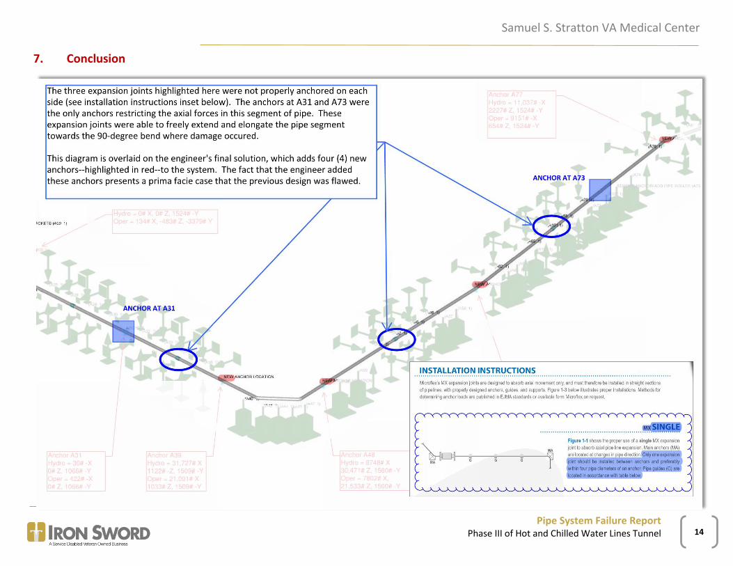
7. Conclusion