Pipeline Construction and Design Standard · PDF file9.1 DESIGN BASIS ... Pipeline...
49
Pipeline Construction and Design Standard
Transcript of Pipeline Construction and Design Standard · PDF file9.1 DESIGN BASIS ... Pipeline...

Pipeline Construction and Design Standard

REVISION STATUS
Section Dot Point Date Pages
Revised Revision Description RVWD APRV
9.10 3 25/06/09 19 New Version BD SM 9.10 4 25/06/09 19 New Version BD SM 9.10 5 25/06/09 19 New Version BD SM
Whole Document 16/12/10 All New Version BD BD Whole Document 28/11/11 All New Version BD BD Whole Document 02/04/13 All New Version BD BD
9.5 20/11/13 16 New Version BD NK 23 23.1 & 2 20/11/13 35 New Version BD NK 5 N/A 20/11/13 7 New Version BD NK 6 N/A 20/11/13 7 & 8 New Version BD NK 7 N/A 20/11/13 13 New Version BD NK
Att 3 N/A 20/11/13 14 New Version BD NK Att 4 N/A 20/11/13 N/A New Attachment BD NK
Attachments 17/01/14 N/A Renumbered Attachments BD BD
INDEX

BUSSELTON WATER Pipeline Construction and Design Standard
3
1. INTRODUCTION ...................................................................................................... 5
2. REFERENCE MATERIAL ....................................................................................... 5 3. GLOSSARY OF TERMS.......................................................................................... 5
4. STANDARD ABBREVIATIONS .............................................................................. 6
SECTION 1
5. PRELIMINARIES TO CONSTRUCTION ................................................................. 7
6. MAJOR AND GENERAL WORKS .......................................................................... 7
7. MINOR WORKS (EXEMPT WORKS) ................................................................... 13
SECTION 2
8. DESIGN GUIDELINES........................................................................................... 14 8.1 REDEVELOPMENT OF EXISTING AREAS........................................................................ 14 8.2 WATER RETICULATION PLANNING FOR SUBDIVISIONS ............................................. 14 8.3 LAND REQUIREMENTS ..................................................................................................... 14 9. TECHNICAL REQUIREMENTS (MAINS) ............................................................. 14 9.1 DESIGN BASIS ................................................................................................................... 14 9.2 BW BASIC DESIGN CRITERIA .......................................................................................... 14 9.3 ADDITIONAL DESIGN CONSIDERATIONS ....................................................................... 15 9.4 ALIGNMENT CONSIDERATIONS ...................................................................................... 15 9.4.1 VALVES............................................................................................................................... 15 9.4.2 LOCATION OF VALVES ..................................................................................................... 16 9.5 HYDRANT INSTALLATION ................................................................................................ 16 9.6 AIR VALVES ....................................................................................................................... 16 9.7 SCOUR VALVES ................................................................................................................. 16 9.8 FLUSHING POINTS ............................................................................................................ 17 9.9 PRESSURE REDUCING VALVES ...................................................................................... 17 10. DRAWINGS ........................................................................................................... 17
11. CONSTRUCTED INFORMATION ......................................................................... 18
12. PRODUCTS AND MATERIALS ............................................................................ 18 13. CONSTRUCTION REQUIREMENTS .................................................................... 19 13.1 CONTRACTOR ACCREDITATION REQUIREMENTS ....................................................... 19 14. PREVENTION OF CONTAMINATION .................................................................. 19
SECTION 3
15. CONSTRUCTION .................................................................................................. 20 15.1 SURVEY AND SETTING OUT ............................................................................................ 20 15.2 HANDLING OF PIPES AND FITTINGS .............................................................................. 20 15.3 PIPE ALIGNMENT AND DEPTH ......................................................................................... 20 15.3.1 ALIGNMENT ........................................................................................................................ 20 15.3.2 DEPTH (MINIMUM COVER) ................................................................................................ 20 15.4 EXCAVATION AND BEDDING ........................................................................................... 21 15.4.1 EXCAVATION ..................................................................................................................... 21 15.4.2 BEDDING ............................................................................................................................ 21 16. PIPE LAYING AND JOINTING .............................................................................. 21 16.1 PREPARATION PRIOR TO INSTALLATION ..................................................................... 21 17. JOINTING .............................................................................................................. 22 17.1 PVC TO PVC PIPES AND FITTINGS .................................................................................. 22 17.2 PVC TO DI PIPES AND FITTINGS ..................................................................................... 22 17.3 DI TO DI PIPES AND FITTINGS ......................................................................................... 22 17.4 JOINTING OF STEEL PIPES AND FITTINGS .................................................................... 22

BUSSELTON WATER Pipeline Construction and Design Standard
4
17.5 PE TO PE PIPES AND FITTINGS ....................................................................................... 23 17.6 PROTECTION OF STEEL PIPES FROM CORROSION ..................................................... 23 18. LAYING OF PIPES AND INSTALLATION OF FITTINGS .................................... 23 18.1 DI PIPELINE SYSTEM ........................................................................................................ 24 18.2 PVC PIPELINE SYSTEM..................................................................................................... 24 18.3 PE PIPELINE SYSTEM ....................................................................................................... 24 18.4 MAJOR ROAD CROSSINGS .............................................................................................. 24 18.5 BRIDGE, TUNNEL AND RIVER CROSSINGS ................................................................... 24 18.6 BENDS AND PIPE DEFLECTIONS .................................................................................... 24 18.7 INSTALLATION OF FITTINGS AND VALVES ................................................................... 25 18.10 VALVES............................................................................................................................... 25 18.10.1 COVERS, FRAMES AND SURROUNDS ............................................................................ 25 18.11 TEMPORARY BLANK ENDS .............................................................................................. 26 18.12 CONNECTION TO EXISTING WATER MAINS ................................................................... 26 19. THRUST SUPPORTS AND ANCHORS ................................................................ 27 19.1 STEEL PIPE ANCHORAGE ................................................................................................ 27 19.3 BACKFILL AROUND VALVES, HYDRANTS, FLUSHING POINTS AND SERVICE CONNECTIONS ..................................................................................................................................... 28 19.4 RESTORATION OF ROAD RESERVES AND ACCESS WAYS ......................................... 28 20. TESTING OF MAINS AND SERVICE CONNECTIONS ........................................ 29 20.1 PREPARATION ................................................................................................................... 29 20.2 FILLING MAINS FOR TESTING ......................................................................................... 29 20.3 TEST EQUIPMENT ............................................................................................................. 30 20.4 OFFICIAL PRESSURE TEST .............................................................................................. 30 20.5 TEST PROCEDURES ......................................................................................................... 30 20.5.1 STEEL, PVC, DI AND COPPER PIPELINE SYSTEMS INCLUDING PE IN CUL-DE-SAC 30 20.5.2 PE PIPELINE SYSTEMS ..................................................................................................... 30 20.5.3 WATER SERVICE CONNECTIONS .................................................................................... 30 20.6 TEST COMPLIANCE CRITERIA ......................................................................................... 30 20.7 RE-TESTING ....................................................................................................................... 31 20.8 POST-TEST REQUIREMENTS ........................................................................................... 31 21. DISINFECTION OF WATER RETICULATION ...................................................... 31 21.1 DISINFECTANT ................................................................................................................... 31 22. PRELAID WATER SERVICE CONNECTIONS ..................................................... 33 22.1 ALIGNMENT AND DEPTH .................................................................................................. 33 22.2 ROAD CROSSINGS ............................................................................................................ 33 22.3 TAPPING RETICULATION MAINS ..................................................................................... 33 23. MISCELLANEOUS WORKS ................................................................................. 34 23.1 ROAD MARKINGS .............................................................................................................. 34 23.2 MARKER POSTS ................................................................................................................ 34
SECTION 4
24. CONTRACTOR REQUIREMENTS ........................................................................ 39
25. JOB SAFETY ANALYSIS ..................................................................................... 40
ATTACHMENT 1 ..................................................................................................................... 42
ATTACHMENT 2 ..................................................................................................................... 43 ATTACHMENT 3 ..................................................................................................................... 44

BUSSELTON WATER Pipeline Construction and Design Standard
5
1. Introduction Busselton Water (BW) Pipeline Construction and Design Standard provides staff, contractors and consultants with guidelines and technical standards for the design and installation of water supplies within Busselton Water’s License area. The standard has been produced to complement existing standards implemented by WSAA Water Supply Code WSA03-2002 and the Water Corporation of WA for the design and construction of water reticulation assets. In the event of conflict between the WSAA Code, the BW Standard shall take precedence.
2. Reference Material
WSAA Water Supply Code of Australia (Water Services Association of Australia) WSA03-2002
Water Corporation Design standard DS 63 and DS 60 Polyethylene Pipeline Code WSA 01 – 1998 (Water Services Association of
Australia) Utility Providers Code of Practice for Western Australia Steel Pipeline System Design Manual (Tyco Water) Steel Pipeline System Handling and Installation Reference Manual (Tyco
Water) Pipe Fittings Standard Drawings (Water Corporation and WSAA)
3. Glossary of Terms Within the standard the following highlighted in bold expressions shall have the following meaning.
As Constructed – Information and measurements provided to locate works relative to existing assets and other supplied survey information.
WSAA Code – The Water Supply Code of Australia WSA03-2002, as published by the Water Services Association of Australia.
BW – Busselton Water. Deferred Services - services to be installed to lots released at a later date by
the Developer. Drawings - water reticulation drawings attached to this standard. Drafting Standards – Busselton Water drafting standards. Lot - a property requiring a reticulation service. MGA94 – Map Grid of Australia 1994. Pre-laid Services - water service connections installed in conjunction with the
construction of new reticulation mains. Standard – Published Busselton Water standard.

BUSSELTON WATER Pipeline Construction and Design Standard
6
4. Standard Abbreviations
AC asbestos cement L litre AHD Australian Height Datum mg milligram AS Australian Standard m metre B/END blank end GRP glass reinforced plastic BL building (property) line mm millimetre BV butterfly valve MSCL mild steel cement mortar lined BW Busselton Water NI not installed CI cast iron OD outside (external) diameter in mm. CU copper ID Internal Diameter in mm. DAV dual orifice double air valve PAW pedestrian access way DI cement lined ductile iron PE polyethylene pipe DN nominal diameter in mm. PN pressure nominal E&C
expanded & collapsed (slip-in)-steel pipe joint
POS Public Open Space
EXIST existing PVC polyvinyl chloride FP flushing point RC reinforced concrete
FW fullway gate valve ROW Right of Way HYD hydrant RRJ rubber ring joint kg Kilogram S Steel kL kilolitre SC scour kPa Kilopascal SV sluice valve

BUSSELTON WATER Pipeline Construction and Design Standard
7
5. Preliminaries to Construction The Water Services Act 2012, Part 6 – Powers in relation to water services works divides all of the works into one of the three categories of EXEMPT, GENERAL and MAJOR Works. The requirements of the Preliminaries to Works procedures differ for each category of works and care must be taken in determining the category of works that are proposed. The Water Services Act allows to carry out all necessary survey and testing work of lands for the proposed works. For the purposes of this document activities to be undertaken prior to construction activities will be called Prelims (Preliminaries to Construction). Refer to the (Preliminaries to Construction Manual) for the preliminary to works requirements and/or approvals that are to be undertaken prior to commencement.
6. Major and General Works Below is the definition of major and general works as stated in the Water Services Act 2012; Major Works are the provision of;
Dams and reservoirs; water storage tanks when constructed have capacity greater than 10ML;
groundwater schemes consisting of bores when constructed have capacity greater than 10ML per day;
irrigation schemes (but not including any irrigation chanel within existing scheme);
water and wastewater treatment plants when constructed have capacity greater than 10ML day;
General Works are the provision of;
Trunk and distribution mains, pumping stations and mains, control and metering stations, main and branch sewers, main drains, irrigation channels, compensation basins;
water and sewerage reticulation mains, other than reticulation mains on land provided at request of the owner of land;
groundwater schemes consisting of bores when constructed will have capacity of 2ML or less per day;
Waste and water treatment plants when constructed will have capacity of 2ML or less per day;
Chemical dosing plants; Water storage tanks when constructed have capacity of 10ML or less per day; Any irrigation channel with an existing irrigation scheme
SECTION 1
BUSSELTON WATER Pipeline Construction and Design Standard
8
Major and general works may require a notice setting out;
description of works; area of works to be located; purposes for works are required; the times when and places at which plans may be inspected information as to how, where and by when an objection to or submission in
relation to the proposal may be lodged. Below are government agencies and a description of advice that can be obtained;
Department of Environment and Conservation (DEC): Within Busselton Water’s Licence Area, DEC is the referral body for State issues relating to the protection of flora, fauna and wetlands. Referrals to DEC are to be made where clearing is required and or crossing wetlands occurs as part of the construction works. When requested, Busselton Water is to undertake all necessary surveys requested. City of Busselton (CoB): The CoB is the controlling body for all local roads within Busselton Water’s License Area. Advice relating to works and issues relating to traffic management and planning shall be submitted to the CoB for comment. Utility Providers (Western Power, Synergy, Gas, Water Corporation, Telstra): Prior to the commencement of any works, Busselton Water shall request all relevant Dial Before You Dig information. Where drainage is considered an issue, Busselton Water shall liaise with the CoB to locate these facilities. Department of Indigenous Affairs (DIA): DIA is the centre of expertise for heritage and cultural issues and maintains a register of Aboriginal sites within Busselton Water’s License Area. Where construction is undertaken in proximity to an Aboriginal site, Busselton Water will initiate a section 18 under the Aboriginal Heritage Act 1972 prior to the commencement of works. Department of Environment and Water Resources (DEW): Within Busselton Water’s Licence Area, DEW is the referral body for Federal issues relating to flora, fauna and wetlands. Referrals to DEW are to be made when carrying out works on nationally protected wetlands. When requested, Busselton Water is to undertake all the necessary surveys [Environment Protection and Biodiversity Conservation Act 1999 (EPBC Act) referral/process shown as per Figures 1 and 2].

BUSSELTON WATER Pipeline Construction and Design Standard
9
Department of Water (DoW): The DoW is the licensing body for water extraction n allocation around the state. Busselton Water shall submit applications for new bore proposals to DoW. Any impacts upon a waterway, discharging, dewatering require notification Main Roads WA (MRWA): The MRWA is the controlling body for all major roads within the State. Advice relating to works and issues relating to traffic management on major roads shall be submitted to MRWA for comment.
BUSSELTON WATER Pipeline Construction and Design Standard
10
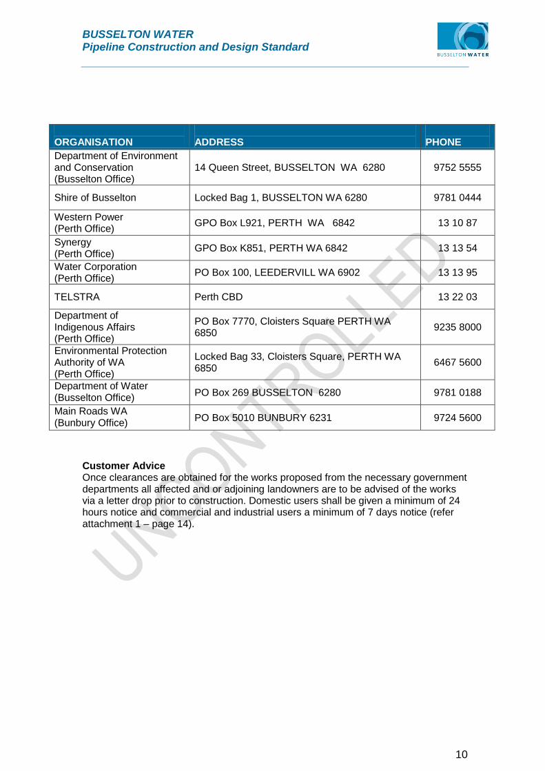
ORGANISATION
ADDRESS
PHONE
Department of Environment and Conservation (Busselton Office)
14 Queen Street, BUSSELTON WA 6280 9752 5555
Shire of Busselton Locked Bag 1, BUSSELTON WA 6280 9781 0444
Western Power (Perth Office) GPO Box L921, PERTH WA 6842 13 10 87
Synergy (Perth Office) GPO Box K851, PERTH WA 6842 13 13 54
Water Corporation (Perth Office) PO Box 100, LEEDERVILL WA 6902 13 13 95
TELSTRA Perth CBD 13 22 03
Department of Indigenous Affairs (Perth Office)
PO Box 7770, Cloisters Square PERTH WA 6850 9235 8000
Environmental Protection Authority of WA (Perth Office)
Locked Bag 33, Cloisters Square, PERTH WA 6850 6467 5600
Department of Water (Busselton Office) PO Box 269 BUSSELTON 6280 9781 0188
Main Roads WA (Bunbury Office) PO Box 5010 BUNBURY 6231 9724 5600
Customer Advice Once clearances are obtained for the works proposed from the necessary government departments all affected and or adjoining landowners are to be advised of the works via a letter drop prior to construction. Domestic users shall be given a minimum of 24 hours notice and commercial and industrial users a minimum of 7 days notice (refer attachment 1 – page 14).

BUSSELTON WATER Pipeline Construction and Design Standard
11
ATTACHMENT 1

BUSSELTON WATER Pipeline Construction and Design Standard
12
ATTACHMENT 2

BUSSELTON WATER Pipeline Construction and Design Standard
13
7. Minor works (Exempt works) Below is the definition of exempt works as stated in the Water Services Act 2012; Exempt works are;
the provision of undertaking of works that are not major or general works; the maintenance or repair of existing works; the making of alterations, extensions or additions to major or general works
that will not materially alter the nature, scope or capacity of the works the making of alterations, extensions or additions to general works on –
(i) land owned by the licensee; or (ii) a reserve under the Land Administration Act 1997, the care, control
and management of which is placed with the licensee under that Act; Exempt works are not subject to provisions as set out for Major and General Works, however utility information is to be requested for these works via “Dial before your dig”. Prior to the construction of exempt works all affected and or adjoining landowners are to be advised of the works via a letter drop. Unless works are carried out in an emergency domestic users shall be given a minimum of 24 hours notice and commercial and industrial users a minimum of 7 days notice (refer attachment 1).

BUSSELTON WATER Pipeline Construction and Design Standard
14
8. Design Guidelines This Part of the Standard sets out drafting and design requirements of Busselton Water (BW). It shall be read in conjunction with Part 1 of the WSAA Code. In the event of conflict between the WSAA Code and this standard, the Standard shall take precedence. 8.1 Redevelopment of Existing Areas The condition and adequacy of existing water supply mains in redevelopment proposal shall be assessed in consultation with BW. 8.2 Water Reticulation Planning for Subdivisions BW will determine the reticulation layout plan including reticulation main sizes and class, location of distribution main valves and hydrants, and capacities of other elements of the system to ensure the supply to and within the subdivision is integrated with the overall water supply scheme. Where required BW will request its hydraulic consultant to undertake the design of reticulation and trunk mains. Prior to the request for hydraulic design BW will request a quote from the consultant and submit this to the developer. Works will not commence until payment is received. 8.3 Land Requirements Fee simple ownership is BW’s preferred land tenure for all it facilities. Where facilities are identified for a particular development land identified for those facilities is to be ceded to BW free of cost. In built up areas BW will negotiate with individual owners.
9. Technical Requirements (mains) 9.1 Design Basis The design methodology provided in the WSAA Code is acceptable to BW, however design criteria in this Standard shall take precedence over the criteria in the WSAA Code. BW requires the developer to pay a design fee for the hydraulic design, the development is then assessed to ensure the pipe network and pipe size meets minimum water licence requirements for the all stages of the development. 9.2 BW Basic Design Criteria Under BW’s existing customer charter BW must supply a minimum static head of 15m and a maximum static head of 100m to every serviced lot within its licence area. BW require all developments to be reviewed hydraulically in context with the water supply system as a whole, the BW consultant will review developments as follows:
Elevations used to meet minimum pressure requirements for an urban property is the ground level found within the front 30 m of the property, the highest contour is to be used to calculate the minimum head. Maximum head is to be calculated using the lowest contour. For larger lots where building envelopes
SECTION 2

BUSSELTON WATER Pipeline Construction and Design Standard
15
are clearly defined, the elevation used for maximum and minimum head calculations may be restricted to the area of the building envelope.
Water reticulation mains shall be sized by BW’s hydraulic consultant. In general the consultant will size mains such that flow velocities are kept below 2 m/sec. Distribution, trunk and supply mains are to assessed on an individual basis however flow velocities generally will not exceed 4m/sec with head losses of between 2 to 3 meters per kilometre considered acceptable.
9.3 Additional Design Considerations BW’s consultant will design BW’s water supply with the following guidelines:
Reticulation mains shall be mains smaller than DN 250. In urban, special rural and or high density development, BW requires a
minimum pipe size of DN 100. 63 MDPE may be considered in cul-de-sacs serving up to 5 single residential lots. The length of 63 MDPE is to be no longer than 100m.
DN 150 pipe shall be used for areas zones industrial and commercial. Larger mains are to be considered to meet future demand. Where practicable the reticulation is to form a series of closed loops to
minimise dead end mains. Where possible a group of 50 or more properties shall be supplied by more
than one pipe route. A Property is to be serviced by a reticulation main along one of its street
frontages (Road reserve). Dead end mains are generally located at the fringe of a reticulation network
and shall be sized to cater for future mains extensions. In general services will not be permitted off a main larger than 200mm.
9.4 Alignment considerations
Mains are to be located within road reserves on an alignment of 2.1m measured from the property boundary in accordance with the Utility Providers Code of Practice Western Australia.
Where road reserves are not available, easements are to be negotiated and provided within Developments on Crown land and or Public Open Space.
Easements shall have a minimum width of 3m and shall where required as part of the subdivision process and shall be transferred to BW free of cost.
Where road reserve vegetation requires clearing BW may request an easement over adjoining private property (eg farmland paddocks). The developer shall consult with the owner for the provision of an easement.
Where possible the number of long services is to be minimised thus road reserves greater than 30m wide shall have mains located on both sides of the road.
If a road crossing is unavoidable, each main should cross the road perpendicular to the road reserve boundary at 2.1m off the lot boundary and in line with property truncation point.
Where a main is to cross a river via a bridge or other structures such as tunnels and or culverts. BW is to be presented with drawings of the proposal and a methodology outlining construction and maintenance issues.
For river crossings where security of supply is considered an issue main crossings shall be above ground.
9.4.1 Valves
BUSSELTON WATER Pipeline Construction and Design Standard
16
Sluice Valves shall be resilient seated – PN16 Clock Close. All valves to be coated and lined. Within a reticulation network, valves are required to isolate the mains for operational and maintenance purposes. Set out below are guidelines for the installation of valves such they create a minimal effect on residents within an area. The network is to be designed to enable the supply of water through alternative mains if the primary main is isolated, without affecting a large number of lots. A primary reticulation main supplies water to a number of secondary reticulation mains. The primary reticulation main is normally a 200mm or 250mm diameter main and supply’s 150mm and 100mm (secondary reticulation) mains. 9.4.2 Location of valves
All secondary reticulation mains supplied from the primary reticulation main have isolation valves at the off -take from the primary main
It is possible to isolate any section of a primary reticulation main by the closure of no more than 10 isolating valves
Isolating any section of reticulation main interrupts supply to no more than 70 residential lots or 20 non-residential lots
It is possible to isolate any section of reticulation (but not primary reticulation main) by the closure of no more than five isolating valves
Valves are to be located opposite street boundary truncation points. Where there is no truncation, the valve shall be located 6m from the street boundary line.
9.5 Hydrant Installation Hydrants shall be WA pattern 100mm screw-down type with integral `yoke SPS 292 with built-in isolation valve and installed only on DN100 or larger pipes. Hydrants shall be installed as per the specifications stated in the Department of Fire and Emergency Services (DFES) Standard for Hydrant Installation. (See attachment 5) The DFES hydrant standard conditions have been developed from the Water Corporation Design Standard 63 for water service infrastructure. 9.6 Air Valves Generally Air valves are not required throughout a reticulation system. However Air valves may be required on supply mains and or trunk mains, where required Air valves are to be as follows:
Air valves, where used in reticulation systems, shall be of DN 50 dual orifice installed with a flanged or threaded isolating valve.
9.7 Scour Valves Scour valves are generally located along reticulation mains located in undulating terrain, or where installation of flushing points is not practical.

BUSSELTON WATER Pipeline Construction and Design Standard
17
Where required, scouring assembly shall include a DN 100 flanged sluice valve and installed to the BW’s requirements.
9.8 Flushing Points All temporary blank ends and dead ends of mains shall be provided with flushing points. 9.9 Pressure Reducing Valves
Pressure reducing valves are not generally required within the BW water network however if required they shall be hydraulically operated and controlled by a Cla-Val CRD pilot control.
Installations are to be above ground and housed in a standard lockable vandal-proof metal cabinet.
Cabinets shall have lockable doors or removable panels with concealed points of fastenings allowing maintenance access. The cabinets shall be subject to acceptance by BW.
Pit type installation is not preferred and will only be approved in special circumstances.
9.10 Services
No services shall be connected directly to a Distribution / Trunk main in a development area.
The number of long services shall be minimised wherever practicable. Each pre-laid service in developments shall be installed at time of water mains
installation to the isolation tap. Each service riser pipe and isolation tap to have stand-up protector. Isolation
taps to be 1000mm from lot boundary for requirement of WP pillar exclusion zone
All short and long single services to be 25mm MDPE. All long dual services to be 32mm MDPE across road protected in a conduit in accordance with Water Corporation standard drawings (Series BD62-8)
9.11 Connections of Water Reticulation to Distribution / Trunk Mains
The location and size of water reticulation mains connected to distribution / trunk mains shall be determined by BW.
For industrial subdivisions, the smallest connection shall be minimum DN 200. If more than 250 services are to be supplied from the connection, then the
connection shall not be smaller than DN 300.
10. Drawings Drawings shall show sufficient detail to clearly indicate the design of the reticulation at a scale of either 1:1000 or 1:2000; drawings are to include the following:
A legend indicating the symbols and abbreviations. A north direction arrow. Water reticulation boundaries.

BUSSELTON WATER Pipeline Construction and Design Standard
18
Street names, Cadastral boundaries, lot numbers and the total number of lots served (Detailing short and long services).
Land use, e.g. duplex, POS, school, multi- residential etc. Land required by BW, Easements etc. Spot levels or contours. Location of existing water mains, and proposed connection details. Pipe material, class and diameter, and total lengths of mains. Alignment of the pipe including location of valves, hydrants, flushing points,
prelaid services and an indication of lots to have deferred services. WAPC Number, plan number and any relevant standard drawings.
11. Constructed Information As constructed documentation shall be supplied to BW by a surveyor and shall be based on measurement from installed cadastral boundary pegs. All As Constructed information shall be to MGA94. As Constructed Drawings are to detail the following:
Text indicating the drawing is an As Constructed is to be placed on the drawing along with the surveyors name and date the As Constructed was undertaken.
The final design plan is to indicate, length of mains, type and class, the final lot layout and location of pre-laid services, valves and hydrants etc.
A digital copy of the plan is to be supplied in either DGN (Preferred) or DWG / DXF format. The as constructed in to be spatially correct using MGA94 coordinate system and all levels are to be based on AHD.
Non standard alignments are to be indicated on the plan in brackets e.g. (1.8)
12. Products and Materials All water reticulation products shall be new and shall have mechanical, corrosion resistant and operational characteristics that render it fit-for purpose in live service. The product shall be packaged such that when it is installed in accordance with the manufacturer’s installation guidelines, it will operate in pressurised water network within the specified operating parameters for at least 50 years prior to any major rehabilitation and or replacement. All elements of water reticulation product in contact with drinking water shall comply with the requirements of AS/NZS4020. All water reticulation systems shall be handed over to BW in a hygienic and disinfected condition. Water reticulation products shall comply with the requirements of the relevant Australian Standard. Pipes used for water mains shall comply with Table 1 below; Table 1
Type of Pipe Class of Pipe
Polyvinylchloride (PVC) PVC-M Series 2 (RRJ) Class 12 AS/NZS 4765
Polyethylene (PE) MDPE PE100 PN10 AS/NZS 4130
Steel Pipe MSCL Sintakote coating

BUSSELTON WATER Pipeline Construction and Design Standard
19
Steel Grade HA1016 to AS/NZS 1594 Polyethylene (PE) (Water Services)
MDPE PE100 PN12.5 AS/NZS 4130
Copper (CU) (Water Services) AS 1432 Type B
Pipe Fittings AS/NZS 2280 Ductile iron coated and
lined to AS/NZS 4158 Rated PN16
13. Construction Requirements Water reticulation shall be constructed to the requirements of BW and to the WSAA Code as required. Construction activities that may impact directly or indirectly on existing BW infrastructure are not permissible unless agreed in writing by BW. 13.1 Contractor Accreditation Requirements Water reticulation construction personnel shall be accredited in accordance with the following accreditation programs, appropriate to the pipeline materials of each project:
Steel pipeline construction - Course in Quality Installation of Sintakote Steel Pipelines (Sintakote Pipelines Program) by Tyco Water. Telephone (03) 9217 3154, facsimile (03) 9305 3963, email [email protected]
PVC pipeline construction - PVC Pipe laying Accreditation Challenger TAFE Fremantle Campus, Telephone (08) 9239 8330, facsimile (08) 9239 8379, Email [email protected]
PE pipeline welding work – Welding Operator Licensed in accordance with the requirements of the Institute of Materials Engineering Australasia Limited (IMEA) Certification Program for
Plastics Fusion Welding. Contact: Licensing Officer, Telephone (03) 9326 7266, facsimile (03) 9326 7272, e-mail [email protected] At least one person in each pipe laying crew shall be accredited except that, for PE pipeline welding work, all welders shall be accredited.
14. Prevention of Contamination During the construction of water reticulation, all materials, components and installation shall be configured so as to prevent any contamination of system water. A high standard of hygiene shall be maintained with respect to the personnel engaged and all materials, tools and equipment used in the construction of the work. In particular materials, tools or equipment used previously on live sewerage work shall not be permissible on water reticulation work. Staff and contractors are to follow BW disinfection processes and procedures as set out in the Procedures Manual Volume 1 Technical (SOP No. 2.2).

BUSSELTON WATER Pipeline Construction and Design Standard
20
SECTION 3
15. Construction 15.1 Survey and Setting Out Water reticulation shall be set out in accordance with the design drawings. Any deviation from the accepted drawings shall be subject to the approval of BW. Once final finished levels are achieved on lot boundaries after the completion of road reserve clearing and road earthworks:
Sufficient cadastral survey pegs and temporary pegs along curved lot boundaries shall be installed to enable the proper construction of the water reticulation. All pegs shall be uniquely marked so as to be clearly identifiable in relation to individual lots.
Cadastral survey pegs installed for the water reticulation work shall remain uncovered and undisturbed and shall be available for the Joint Final Inspection. Any disturbed cadastral survey pegs shall be re-established by a Licensed Surveyor.
15.2 Handling of Pipes and Fittings All pipes and fittings shall be handled and installed in a manner that will prevent physical or structural damage to pipes, coatings, linings and elastomeric seals. Pipeline components including coatings and linings that are damaged, including scored pipe surfaces, and cement lining cracks larger than 0.1mm shall be rejected. Pipes and fittings that have coatings or linings of polymeric or plastic materials shall not be exposed to the external environment for more than 12 months. Prior to use all pipes are to be checked to ensure they are not out of date. Out of date materials will be rejected by BW. 15.3 Pipe Alignment and Depth 15.3.1 Alignment Installation of Pipe shall not commence until the cadastral survey pegs required to determine the pipe alignment are in position. The following requirements shall apply unless otherwise shown on Drawings:
Alignments shall generally be in accordance with the Utility Providers Code of Practice, (Water mains 2.1m); 1.8m alignment may be considered and approved by BW where clashes with other services occur.
In a common trench, the water reticulation main shall be laid with other services in accordance with the alignments and depths shown on the design drawing.
Mains shall be laid true to line within 100mm from their correct alignment, except where obstacles prevent access to the alignment. In such instances, a proposal that is acceptable to all utilities shall be submitted to BW. Agreed alignment variations shall be documented on the As Constructed Drawings.
15.3.2 Depth (Minimum Cover)

BUSSELTON WATER Pipeline Construction and Design Standard
21
Generally pipes shall be laid as straight as practicable and in compliance with manufacturer’s recommendations while maintaining the appropriate minimum cover of 700mm. Where a change in grade occurs the mains shall be laid to avoid exceeding the maximum allowable deflection allowed under the manufacturers recommendations.
A minimum clearance of 100mm all around shall be maintained where the main is to be installed in close proximity to existing and or proposed services.
The depth to the top of the pipe from the final verge level and the gutter level shall be established at intervals not exceeding 50 metres and recorded on the As Constructed Drawings.
Concrete encasement or protective cover slabs are not permissible as alternatives to maintaining minimum pipe cover.
15.4 Excavation and Bedding Prior to excavation works all utility facilities are to be located and potholed and any service clashes reported to BW before installation of the mains. 15.4.1 Excavation Where open trench excavation is proposed, pipe trenches shall be excavated to alignments, depths and widths required by the design drawings. The following requirements shall also apply:
Where necessary trenches shall be dewatered until each section of main has been completed and tested.
Groundwater shall not be allowed to enter pipes. Over excavation of the trench shall be backfilled and compacted with suitable
bedding material. Where open trench excavation is not practicable, such as across major roads, freeways and railways, under major obstructions, and wherever shown on the Drawings, the pipeline shall be installed by trenchless technology. The methods shall be to the requirements of the controlling authority (eg MRWA) and acceptable to BW. 15.4.2 Bedding Bedding material shall be in accordance with the Drawings and shall meet the following requirements:
For trenches in sand the natural soil at the trench bottom shall be compacted. For trenches in gravel and or non-granular soils the trench shall be over-
excavated by at least 150mm, in depth and refilled with suitable imported bedding material, and compacted.
In all cases the trench bottom shall be hand trimmed immediately before placing the pipe to provide even support to the whole pipe barrel.
16. Pipe Laying and Jointing 16.1 Preparation Prior to installation
BUSSELTON WATER Pipeline Construction and Design Standard
22
Pipes shall be examined for cracks, scoring, gouges or any other defects.
Where defective pipes are identified they will be rejected by BW. Sand and other foreign materials shall be removed from the pipe bore. And jointing pipe spigots, socket surfaces and elastomeric rings are to be
cleaned.
17. Jointing 17.1 PVC to PVC Pipes and Fittings Joints between PVC pipes and fittings shall be made with elastomeric seals in accordance with the manufacturer's instructions:
Pipes are to be installed in a straight line prior to making the joint. Only jointing lubricant specified by the pipe manufacturer is to be used Socket joints are to be adequately restrained to prevent movement during the
jointing process Spigot Joints are to be pushed home in a manner recommended by the pipe
manufacturer until the witness mark is just visible. Pipes damaged during the jointing process are to be removed and replaced. Where PVC pipe is cut on site, the cut end shall be chamfered and witness
marked in accordance with the manufacturer’s instructions. 17.2 PVC to DI Pipes and Fittings
PVC socket ends shall be jointed with matching PVC spigot ends only in order to achieve a watertight joint.
No metallic pipe or pipe fitting spigots shall be jointed to PVC socket ends. Where a PVC pipe is cut on site, the cut end shall be chamfered and witness
marked in accordance with the manufacturer’s instructions without damaging the pipe.
17.3 DI to DI Pipes and Fittings
Ductile iron pipes shall be jointed with elastomeric joint seals in accordance with the manufacturer’s instructions:
Each seal is to be retained in the socket groove of the previously laid pipe without any twist or buckle.
The spigot end of the pipe is to be laid and centred within the elastomeric seal and supported until the jointing process is completed.
The pipe is “pushed home” firmly and straight in the socket of the previously laid pipe and is to be restrained from springing back.
Each spigot end of a cut pipe shall be chamfered in accordance with the manufacturer’s instructions.
17.4 Jointing of Steel Pipes and Fittings Elastomeric seal jointed steel pipes shall be installed in compliance with the manufacturer’s instructions. Fittings shall be welded as for weld-jointed steel pipes.

BUSSELTON WATER Pipeline Construction and Design Standard
23
Where steel pipes are weld-jointed, installation shall be in accordance with the Steel Pipeline System Handling and Installation Manual and the following requirements:
All pipe welding shall be in accordance with AS 4041 Pipe work Class 2P, Corporation Welding Specification WS-1 and the Drawings;
Pipe flanges for valve connections shall be welded to pipes in accordance with the Drawing DS 65 AY58-15-1 of the Water Corporation Pipe Fittings Standard Drawings;
Welding procedures and qualification of each welder and welding operator shall be in accordance with AS4041 and the requirements of Corporation Welding Specification WS-1;
Where the cement mortar lining of a pipe or fitting cannot be readily reinstated at the welded joint, a convex band shall be welded over the joint. When the band has cooled, it shall be fully injected with cement grout through a hole in the bottom or side which is then sealed with a welded cap once the grout has set;
All cut ends and welded areas shall be protected as required by sub-clause “Protection of Steel Pipes from Corrosion” under 17.6.
Welded joints may be subject to visual examination by BW for acceptance of welding work.
17.5 PE to PE Pipes and Fittings
PE pipes and pipe fittings and their jointing shall comply with the requirements of, and including limitations in Table 3.1 of Part 3 of the WASS Standard.
Where butt fusion weld jointing is expressly permitted, the pipes shall be prepared for welding in accordance with pipe manufacturer’s recommendation.
17.6 Protection of Steel Pipes from Corrosion
Damaged pipe coating shall be primed, filled with butyl mastic and wrapped with a 2mm thick reinforced bitumen mastic with PVC backing (Densopol 80, Rockrap 4000 Tape System or approved equivalent), in accordance with the manufacturer’s application specification.
All welded joints, bands, bends, tees, flanges; flange and valve body assembly bolts shall be primed and wrapped with a butyl mastic tape and PVC overwrap system (Denso or approved equivalent) in accordance with the manufacturer’s application specification.
For pipes emerging from below ground, the tape wrapping shall extend to 100mm above the finished ground level.
Where a protective coating system is used, pipeline and valve surfaces shall be prepared so that rust and any other deleterious materials are removed in accordance with the coating manufacturer’s requirements
In all circumstances, the minimum surface preparation requirements shall be degreasing and mechanical wire brushing to obtain a Class 2 cleanliness in accordance with AS 1627 Part 2.
18. Laying of Pipes and Installation of Fittings Pipes shall be laid to the following general requirements. At the end of each day's work or at any time when pipe laying is suspended, every open end of each

BUSSELTON WATER Pipeline Construction and Design Standard
24
incomplete pipeline shall be plugged with a tapered stopper or an acceptable end cap matching the pipe. No tools or any construction materials shall remain in the pipes. 18.1 DI pipeline system
Purpose made polyethylene sleeving shall be installed in accordance with the pipe manufacturer’s recommendations.
Any rupture in the sleeving due to damage shall be overwrapped and securely taped.
18.2 PVC pipeline system
PVC pipelines shall be laid in accordance with manufacturer’s instructions and in accordance with the practices recommended in the PVC pipe laying accreditation course.
18.3 PE pipeline system
PE pipelines shall be laid in accordance with manufacturer’s instructions and practices recommended in the PE butt welding accreditation course.
Allowance shall be made for the likely pipe movement due to temperature changes during installation and commissioning. A final service temperature of 20º±5ºC may be assumed unless otherwise specified in the Drawings. Pipe lengths and bend locations shall be adjusted for changes in length that will occur when the temperature stabilises at the final service temperature.
The trenches shall not be backfilled unless the ambient temperature is within ±5ºC of the final service temperature.
PE pipes within the trench may “snake” if the final “snaked” alignment at the final stabilised service temperature is within 100mm of the correct alignment.
18.4 Major road crossings
The pipes shall be laid continuous under road pavement and extend 1.5 metres beyond the road shoulder. The pipeline under the road pavement shall not contain:
an elastomeric seal or mechanical joint; An electrofusion fitting or butt-welded joint in a PE pipe, if the crossing is
constructed by trenchless method without being encased in a pipe sleeve. Mild steel weld-jointed pipes shall have external fusion bonded polyethylene
coating and internal cement lining and shall be in the longest practicable lengths, to minimise the number of welded joints under the road pavement.
18.5 Bridge, tunnel and river crossings
Each crossing proposal shall detail the construction methodology together with the approval of relevant authorities and shall be submitted to BW for consideration and acceptance.
18.6 Bends and Pipe Deflections

BUSSELTON WATER Pipeline Construction and Design Standard
25
A pipeline required to follow a long curve may be laid and jointed with deflections at the joints. The maximum angular deflection at a pipe joint shall not exceed the pipe manufacturer’s recommendations. Bending of pipes to achieve a curve or for any other purpose is prohibited, except for PE and CU pipes.
PE pipes may be laid in a curve of radius that is not less than the manufacturer’s recommendations.
An acceptable pipe-bending tool shall be used to bend CU pipe. Crimped or distorted pipes shall be rejected.
Where the required angle change exceeds the permissible joint deflection, standard bend fittings shall be used.
Bends shall be installed opposite cadastral survey pegs unless otherwise shown on the Drawings and or accepted by BW.
Where a bend is required on a truncation at which a valve is also required, the bend and the valve shall be separated by an 800mm minimum length of straight pipe.
18.7 Installation of Fittings and Valves
The mating flanges of all flanged joints where dissimilar metal contact may occur shall be electrically isolated by means of acceptable flange insulation kits.
The inside of all valves, hydrants and fittings and the mating surfaces of the spigot ends, collars, flanges and rubber rings shall be cleaned immediately prior to installation and before jointing.
Pipes shall be cut to ensure installation of fittings in the correct location. The minimum pipe length between adjacent elastomeric seal jointed fittings shall be 1000mm without anchorage and 800mm with anchorage.
18.8 Hydrant Risers
A double flanged hydrant riser pipe of the appropriate length shall be installed on a hydrant tee to suit the final verge level above the tee. The hydrant installation shall then be completed in accordance with the Water Corporations Standards Drawings. (Series BD62-2-1)
18.9 Flushing Points
Flushing points on all permanent and temporary blank ends shall be installed in accordance with the Water Corporations Standards Drawings (Series BD62-2-2) and in the locations designated on the approved construction drawings.
If a sluice valve and a bend are both required at a truncation, the valve may, subject to agreement, be displaced from the point opposite the truncation by 800mm. The valve shall be positioned in the location least likely to be paved.
18.10 Valves
All valves and fittings that are non-compliant or defective shall be rejected. 18.10.1Covers, Frames and Surrounds
Covers, frames and service chamber assemblies for sluice valves, gate valves, stop valves, hydrants and flushing points shall be installed so that the cover

BUSSELTON WATER Pipeline Construction and Design Standard
26
level is flush with the final surface level and to the requirements shown on the Drawings.
Valve Box to have BW moulded in top painted Blue. Busselton Water own pattern and request valve boxes to be purchased from Busselton Water.
18.11 Temporary Blank Ends
Temporary blank end caps shall be installed on new pipelines to be connected to existing water mains. The end caps shall be installed approximately 4m from the existing water main and shall be clear of any pavement.
Temporary blank ends shall be adequately anchored to withstand test pressure.
18.12 Connection to Existing Water Mains Work on or connection of new pipelines to existing water mains is not permissible unless:
Written acceptance has been obtained from BW. All required pressure testing of the new water reticulation has been
successfully conducted and accepted. The new water reticulation has been disinfected in accordance with section 22
of the standard. New mains shall be laid at the specified depths and alignments after
ascertaining by manual excavation methods the positions of other existing services in the vicinity.
Interference with, or operation of any existing main or valve or fitting is not permitted unless approved by BW.

BUSSELTON WATER Pipeline Construction and Design Standard
27
19. Thrust Supports and Anchors Thrust supports for permanent installation shall be of concrete. For temporary installation, repairs and where concreting work is impracticable, jarrah timber may be used. Thrust supports for multiple or compound bend arrangements shall be of concrete only. (Refer attachment 1 for standard concrete thrust supports) Flange bolts shall be installed with the washers and nuts furthest from any concrete thrust support. Bolt heads must not be encased by the concrete. Corrosion protection of the flange bolts shall be carried out prior to construction of concrete thrust supports. Thrust supports shall not extend more than 300mm from nominated alignments except where other accepted by BW. Thrust supports shall be installed and the trench backfilled and compacted prior to commencement of pressure testing. 19.1 Steel Pipe Anchorage
Buried Steel Pipeline Where buried steel pipes are used, thrust supports may be replaced by welded pipeline sections installed on both sides of the fittings as indicated in Table 1. Table 1
Size DN(mm)
Min Length of Weld (m) each side of pipe
45 Degree Bend
60 Degree Bend
90 Degree Bend
100 6 10 30 150 6 10 30 200 6 15 40 250 6 15 40
Note: The lengths are valid for; maximum hydraulic pressure of 1200 Kpa in pipe, and a minimum 600mm well compacted soil cover over pipes.
BUSSELTON WATER Pipeline Construction and Design Standard
28
19.2 Backfill Initial backfill shall be selected fill material placed and compacted to provide continuous support to the pipe as shown in the standard drawings. Initial backfill at the sides and up to 150mm above the pipe shall be well compacted so that no joints or pipes are disturbed or damaged. All joints shall be left exposed until the preliminary pressure tests have been successfully completed. Final backfill of pipe trenches shall be carried out to the requirements of the Drawings. Where the excavated soil is not suitable for final backfill, imported granular material complying with the requirements shall be imported for backfill. Except where thrust support by backfill is required for pressure testing, final backfill shall not be carried out until:
the As Constructed measurements have been taken for pipes and fittings in pipe trenches;
The Official Pressure Test is accepted, and height and position have been complied with for service risers.
Where backfill is required to provide thrust support, for pressure testing, it shall be carried out only after the As Constructed measurements have been taken. Any backfilling carried out prior to complying with the above requirements will be rejected and the reticulation may be required to undergo a further pressure test. Compacted final backfill shall be finished as follows:
In a road verge - levelled to the final verge level. Within a pavement area - to the levels meeting the road authority’s
requirements for the pavement construction. At service tapping points and around service risers – to the agreed final ground level. Sections of water reticulation damaged and repaired during backfilling will require another official pressure test after reinstatement 19.3 Backfill around Valves, Hydrants, Flushing Points and Service
Connections Granular material shall be used for backfill around all valves, hydrants, flushing points and service connections. 19.4 Restoration of Road Reserves and Access Ways After backfill pavements in road reserves or access ways shall be temporarily reinstated and maintained in a safe condition for vehicles and pedestrian traffic. The final surface treatment, including restoration of road pavements, footpaths, landscaping and vegetation shall be to the requirements of the road authority.

BUSSELTON WATER Pipeline Construction and Design Standard
29
20. Testing of Mains and Service Connections
Each pipeline and service connection shall be subjected to a successful preliminary pressure test before carrying out the Official Pressure Test. Official Pressure Tests shall be witnessed by the Construction Engineer and a Busselton Water representative. Details of each Official Pressure Test shall be recorded on a Pressure Test Record Sheet included in this part of the Standard. Each record sheet shall be kept and a copy submitted to BW for its records. Water service connections may be pressure tested separately to, or in combination with reticulation mains. The tapings and all riser joints and fittings shall remain exposed to allow viewing during the pressure test.
The use of sealant or similar products to plug any detected leakage is not permitted.
20.1 Preparation
Mains shall not be tested until at least 24 hours after concrete thrust supports have been constructed. The following requirements shall be met prior to testing:
The difference in elevation between any two points on the section of the main
under test shall be not greater than 30 metres; At least 300mm of suitable fill material shall be placed over the initial backfill
for the section of pipeline to be tested, leaving all meter risers, stop tap, water service tapings and hydrant tee flanges exposed to view;
The pressure test gauge shall be located as close as practicable to the lowest point of the test section.
All water service tapping points and riser joints included for the pressure test shall be exposed for inspection. All property service stop taps shall be in the open position and have their outlets plugged at the time of testing;
Where a valve is shut to form one end of a test section, suitable temporary supports shall be installed to prevent the valve moving due to unbalanced hydraulic thrust.
No pressure testing against valves on live mains shall be conducted prior to approval from BW.
20.2 Filling Mains for Testing
The section of the main to be tested shall be filled gradually with potable water acceptable to Busselton Water. Filling of the main shall be completed at least 24 hours prior to the commencement of the Official Pressure Test. For cement mortar lined pipelines this period shall be 48 hours prior to testing to allow for absorption.
Water for testing purposes may be obtained from the BW live mains provided prior approval has been given by, and detail arrangements for the draining of test water have been made with the BW.
Air from the test section should be expelled. If necessary, temporary air vents may be provided by the use of appropriate tapping band. Temporary air vents shall be removed upon completion of the test and the tapping point sealed with a suitable plug.

BUSSELTON WATER Pipeline Construction and Design Standard
30
20.3 Test Equipment
Main or isolated sections of the main shall be pressure tested by means of a pump capable of raising and maintaining the hydraulic pressure for the duration of the test.
A calibrated pressure gauge of minimum diameter 100mm and maximum 50kPa pressure graduation intervals shall be connected to the pipeline to be tested.
20.4 Official Pressure Test
Each test section shall be subjected to a hydraulic pressure test of 1.25 times the design pressure (H) for the section under test (1.25H), or 1200 kPa (120m head of water) whichever is the higher, as measured at the lowest point of the test section, unless otherwise requested by BW.
20.5 Test Procedures
For all water reticulation systems the test shall be carried out with the test pressure maintained for as long as necessary to inspect all joints and fittings within the test section by a Busselton Water representative. The duration of the test shall not be less than one hour. The Construction Engineer and or representative shall give no less than 48 hours’ notice prior to the water pressure test.
20.5.1 Steel, PVC, DI and Copper Pipeline Systems including PE in Cul-de-Sac
The test shall be carried out as outlined in the Code generally except that no water loss or pressure drop during the test shall be acceptable.
20.5.2 PE Pipeline Systems
The test shall be carried out as outlined in Section 2.13 of WSA 01 as in the Extract attached at the end of this Part, except for the test pressure and test duration requirements herein.
20.5.3 Water Service Connections
Each water service shall be flushed for its full length with water from the main to remove any foreign matter or air. The outlet of the stop tap shall then be sealed with a brass or plastic threaded plug and the stop tap turned on before commencing the pressure test. During the test the copper riser pipe shall be lowered or raised and the rotated joint inspected for leakage.
20.6 Test Compliance Criteria
Subject to all test preparation and procedures being adhered to, a pressure test shall be acceptable if the following are met:
There is no visible leak or evidence of leakage detected from the
sections/mains being tested. There is no loss of water from any pipeline section under test. There is no visible leak or evidence of leakage from all water service tapping
point or riser joint during testing.

BUSSELTON WATER Pipeline Construction and Design Standard
31
20.7 Re-Testing
If a test section fails the pressure test, the cause of failure shall be determined and rectified. The section shall be re-tested until an acceptable test result is achieved.
20.8 Post-Test Requirements
After satisfactory completion of the pressure test, the test section shall be left charged. All sluice valves and section gate valves shall be left fully opened and all hydrants, flushing points and tapping at temporary dead ends shall remain closed.
After successful pressure test and before backfilling of a pipe trench, the stop tap in the service connection shall be turned off. The stop tap shall then be fitted with a fabricated “stand-up service protector” and the stop tap outlet fitted with a security plug in accordance with Water Corporation Drawings (Series BD64 -9-1 and 2).
21. Disinfection of Water Reticulation The water reticulation shall be disinfected as part of the filling and pressure testing processes, unless otherwise accepted. Water reticulation disinfection work shall not proceed until a Disinfection Plan has been submitted to and accepted by BW. Each Disinfection Plan shall provide the following details:
Disinfectant and dilution water quantities proposed for each disinfection batch or operation.
The progressive stages of disinfection operations as defined by the valving sequence proposed.
The disinfection dilution and injection equipment proposed; The timing of each disinfection operation. The methodology proposed for flushing of disinfectant waste and the disposal
arrangements acceptable to the local and environmental authorities. At any stage during the filling and testing of mains, BW may request that all
mains to be tested be flushed until the water is clear of all foreign material. During filling, disinfectant shall be added to the main in accordance with the
requirements in of section 22.1, ensuring that the disinfectant is thoroughly mixed with the filling water and evenly distributed.
Where practicable, the common reticulation valves shall be operated progressively after two or more adjoining sections have been successfully pressure tested. The disinfectant shall be progressively introduced until the reticulation has been fully disinfected.
The diluted disinfectant shall be retained in the water reticulation for as long as practicable which shall not be less than 24 hours. The main shall then be drained and flushed with potable water. All waste and flushed disinfectant shall be disposed of in an environmentally acceptable manner in accordance with the requirements of the local and the environmental authorities.
21.1 Disinfectant
Disinfectant shall be calcium hypochlorite powder rated to yield 65% available chlorine, or sodium hypochlorite liquid rated to yield 12% available chlorine. The disinfectant shall be diluted with water for injection into the water

BUSSELTON WATER Pipeline Construction and Design Standard
32
reticulation to be disinfected so that the effective strength of the diluted product provides a dosing rate of 20mg/L measured as free chlorine.
The disinfectant dilution guidelines in the following table maybe used to calculate the appropriate disinfectant and dilution water quantities in each case.
Table
NOTE: For a dose rate of 20mg/L: 10kg of calcium hydrochloride will treat 325 KL of water/ 20 L of sodium hydrochloride liquid will treat 120 KL of water
Nominal Pipe Diameter
(mm)
Nominal
Volume in Pipe
Calcium
Hypchlorite Powder (65% C1
2)
Sodium
Hypochlorite Liquid (12% C12)
kL of Water
per 1000m of Pipe
kg used for
1000m of Pipe
Litres used for 1000m of Pipe
50
2
0.06
0.4
100
7
0.20
1.2
150
17
0.50
2.8
200
33
1.00
5.5
250
49
1.51
8.2
300
68
2.10
11.3
BUSSELTON WATER Pipeline Construction and Design Standard
33
22. Prelaid Water Service Connections Prelaid water service connections in new subdivisions shall be installed in accordance with the Drawings. 22.1 Alignment and Depth Water services shall be installed where shown on the Drawings in accordance with the typical arrangements shown on the Drawings contained in Part 4 of the Standard. Where it may prove impracticable to comply with the requirements due to concealed obstructions, alteration will require BW approval. A minimum of 100mm clearance all round shall be provided for all water service pipes relative to other services. 22.2 Road Crossings Road crossings for service connections shall be installed prior to the construction of the road. Immediately after installation the ends of the service pipes shall be temporarily enclosed with a plastic bag securely fastened with adhesive tape. 22.3 Tapping Reticulation Mains Service tapping locations on water reticulation mains shall be located within 100mm of the standard service alignment unless constrained by the following:
A minimum of 300mm from a pipe or pipe fitting socket. A minimum of 300mm from an adjoining tapping. When tapping PVC and PE mains, the swarf and coupon shall not be
permitted to fall into the main. The tapping band shall be installed so that the off-take is centrally positioned
over the tapping hole in the main and in accordance with the Drawings in Part 4 of the Standard.
90˚ Brass elbow (male to female) must connect from tapping band to service pipe work.
Fittings shall be assembled and jointed in accordance with the manufacturer's recommendations.
Each threaded joint shall be sealed with PTFE thread tape or Teflon jointing compound applied in accordance with the manufacturer's recommendations.
Tapping or service pipe work which is positioned more than 200mm from the standard or agreed service location in the road reserve or 100mm within a property will be deemed defective and will be rejected by BW.

BUSSELTON WATER Pipeline Construction and Design Standard
34
23. Miscellaneous Works 23.1 Road Markings Road markings shall be provided and installed by the contractor to indicate the location of valves and permanent flushing points. The kerb marking, shall be placed adjacent to the fittings and marked with a suitable blue line marking paint. Blue cats eyes required to indicate Hydrants shall be installed by the contractor. Specification and installation procedures are available by contacting DFES. 23.2 Marker Posts A flexible metal marker post shall be provided and installed to indicate the position of hydrants. The posts shall be installed no more than 45cm to the rear or front of the hydrant. Refer DFES for identification and marking requirements.

BUSSELTON WATER Pipeline Construction and Design Standard
35
WATER RETICULATION OFFICIAL PRESSURE TEST RECORD SHEET
Subdivision Estate Name/Description of Main: ………………..………………………………………………………………………………... …………………………………………………………………………………………………. Busselton Water File No………………………………. WAPC No:………………………….. Busselton Water Drg No:……………………………………………………………………… . Busselton Water Assessment Officer: ………………………………………………………………………………….. Contractor: ………………………………………………………………………………………………… Mains Tested in accordance with the requirements of Busselton Water’s Water Reticulation Standard.
MAIN DIA. TYPE LENGTH REMARKS
NOTE: There are no allowable leakage rates for any type of pipe. Date Tested: ………………………………………………………………………….PASSED/FAILED Test Pressure…………………………………………………………………….. kPa Duration of Test MINUTES Signature of Contractor’s Representative Date: Name of Contractor’s Representative: ………………………………………………………………………………………………….. Witnessed By: Busselton Water Assessment Officer Date

BUSSELTON WATER Pipeline Construction and Design Standard
36
EXTRACT (SECTION 2.13) FROM WATER SERVICES ASSOCIATION’S
POLYETHYLENE PIPELINE CODE WSA 01-1998 TESTING AND COMMISSIONING General The traditional testing procedure used for most pipeline materials throughout the water industry requires the pipeline to be filled with water, raised to the test pressure and then sealed. The pressure in the pipeline is then monitored, and the pipeline inspected for any leakage or failure of any pipeline components. A maximum acceptable water loss rate or loss volume is specified for acceptance purposes. These procedures are strictly not applicable to viscoelastic materials such as PE since PE pipes exhibit creep and stress relaxation. When a PE pipeline is sealed under a test pressure there will be a reduction in pressure, even in a leak free system, due to the creep response of the material. Two pressure tests have been described below. The basic pressure test (visual) is recommended for pipe sizes <= DN 250 for residential locations using both standard trenching and rehabilitation techniques. The general pressure test (technical) is recommended for the remaining installations where the consequences of pipeline leakage or failure are more significant. The objective of the field pressure test is to test the jointing and installation, not the material capability. With a safety factor of 1.25 for PE coupled with relatively flat regression curves, the maximum test pressure and test duration for field testing needs to be carefully chosen whenever there is a possibility of elevated (>20
0C)
temperatures during testing. In such cases the multiplication factor adopted should be reduced to say 1.2 to 1.3. Basic Pressure Test (Visual)
For completed line testing, a test pressure of 1.25 times the maximum working pressure shall be applied for a minimum of 15 minutes without leakage, or for sufficient time to permit visual inspection of the line.
Test water shall be introduced to the pipeline and time allowed for the temperature to stabilise in the pipe to overcome any volume change effect.
Test pressures shall not exceed the design safety factor for the material.
Compressed air testing shall not be permitted for pressure pipe.
Where hydrostatic test pressures are applied to PE pipelines, the current water utility techniques for valve operation, air removal, and length of test sections adopted for PVC pipe shall be utilised.
General Pressure Test (Technical) General When a PE pipe is sealed under a test pressure there will be a decay in pressure, even in a leak free system, due to the creep response and stress relaxation of the material. Due to this material behaviour, standard pipe testing procedures used for other pipe materials such as DICL and steel, are not suitable for PE pipe. A procedure for pressure testing PE pipelines has been developed in the UK and is outlined in the “Manual for Polyethylene Pipe Systems for Water supply Applications”,

BUSSELTON WATER Pipeline Construction and Design Standard
37
produced by the Water Research Committee (WRc). The test procedures set out below are based on the procedures in this standard. Test Principle The principle of the testing procedure is that the plot of the log of pressure versus the log of time, for a pressurised pipeline will result in a straight line, if there are no leaks and no entrapped air. The slope of the line should be within a certain range, based on experience in the UK. Test Pressure For PE pipe systems the recommended test pressures at <=20
0C are as follows:
• for PN 6 and PN 10 systems, 1.5 times the Rated Pressure,
• for PN 12.5 and PN 16 systems, 1.5 times the Working Pressure.
Where systems have components of different pressure ratings, care should be taken to ensure that the test pressure does not exceed 1.5 times the rated pressure of the lowest rated component. For example, in a PE pipeline system using PN 12.5 pipe with a mixture of PN 10 and PN 12.5 fittings which operates at a maximum working pressure of 110 metres, the recommended test pressure should not exceed 150 m, despite this being less than 1.5 times the working pressure. Test Procedure The test procedure shall be as follows:
• Backfill the pipeline-joints may be left exposed if required (the results of the test may vary if the pipeline is not restrained by backfilling and a steeper curve should result).
• Fill the pipeline from the lowest point making sure that all air is removed. • Leave the pipeline to stabilise at its temperature until the next day. • Apply pressure to the main by pumping continuously at a constant rate.
Record the time tL (pressure loading time) taken to raise the pressure to the test pressure from the starting pressure.
NOTE: Long duration may mean the presence of entrapped air-the test should be stopped and the air removed. (v) Once the test pressure has been reached, the pipeline is isolated and the pressure allowed to decay. (vi) Pressure recordings (in metres head) are taken at selected intervals of time. The
greater the number of pressure readings taken the more reliable the analysis. However, a minimum of three recordings is required:
• the first pressure reading P1 shall be taken at t
1 , where t
1 is equal to the pressure
loading time, tL or 10 minutes, whichever is greater. • the second pressure reading t
2 shall be taken at a time, t
2 , of approximately 7tL.
NOTE: Because the pipeline begins to relax within the period of pressurisation, a correction factor has to be applied to the time. Experience suggests that this should be O.4tL). t1c=t
1 + O.4t
L
t2c=t
2 + O.4t
L
BUSSELTON WATER Pipeline Construction and Design Standard
38
(vii) The measurement of the slope of the pressure decay curve between t1 and t
2 is
then calculated as the ratio n1:
n
1=(logP
1-logP
2)/(logt
2c-logt
1c)
Enter results in table (refer to table below) (a) For an acceptable main, experience suggests that n
1 should be between 0.04 to
0.05. For pipelines that are unconstrained, eg. slip lined or pipe cracked, n
1 should be
between 0.08 to 0.10 (b) If value of n
1 is significantly less than in (a), there is too great a volume of air in the
main. (c) If the value of n
1 is significantly greater than in (a), it is likely that there is a leak.
The third pressure reading P
3 is taken at a decay time t
3 not less than 15 tL. The
corrected value for t3 is:
t3c=t
3+0.4t
L
The measurement of the slope of the pressure decay curve between t2 and t
3 is then
calculated as the ratio n1
n2
=(logP2
-logP3
)/(logt3
c-logt2
c)
The value n
2 should be between the same ranges as n
1 (see (a) above).
The sensitivity of the analysis can be increased by extending the value of t3 (ie.
extending the test duration). The results (log P versus log t
c) when plotted should yield a straight line if there are no
leaks. If the test results when plotted shows that there may be leaks, the pipeline route shall be inspected for leaks which, when detected, shall be rectified. The pressure in the main shall be released slowly to pre test conditions. The pipeline shall then be retested after a period equivalent to at least 5 times the previous total test period. Commissioning The established water business flushing and disinfection methods currently used for PVC and DI pipe shall be adopted for PE pipe. These methods may be adapted to meet particular PE installation conditions, e.g. pre-chlorination of sliplined mains.
BUSSELTON WATER Pipeline Construction and Design Standard
39
24. Contractor Requirements This section is to be read in conjunction with section 3 and sets out contractors obligations and requirements in relation to works undertaken for and on behalf of BW. In general works undertaken by contractors will be either within the road reserve or on freehold BW sites. In all cases the contractor will be required to adhere to the highest possible standards for Occupational Health and Safety. The contractor will need to demonstrate to BW that all the necessary procedures, accreditations and insurances are in place as follows.
Provision of up to date copies of insurances relating to Workers compensation and Public Indemnity.
Certificates required to undertake the works to be carried out (eg working at heights, working in confined spaces etc)
Relevant experience in similar size and type of work. Submission of a Job Safety Analysis (JSA) reviewing risks and proposals to
reduce risk (See attachment for BW JSA). Any relevant licenses specific to the works to be undertaken.
The contractor at all times will be required to ensure the site is kept clean, tidy, safe and secure and that appropriate bunting , signage, traffic management and traffic control is in place. Contractors are to ensure all the necessary PPE are made available to its employees. Failure to comply with one or of the above will result in the issue of a stop work notice.
SECTION 4
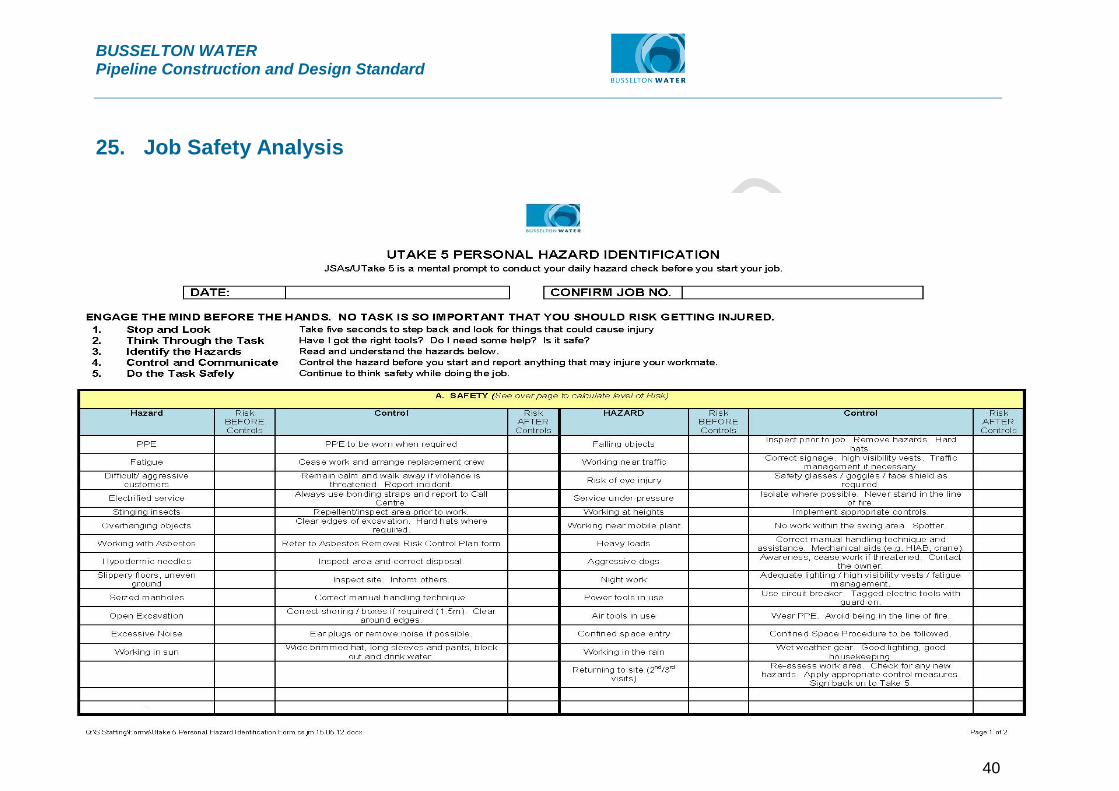
BUSSELTON WATER Pipeline Construction and Design Standard
40
25. Job Safety Analysis
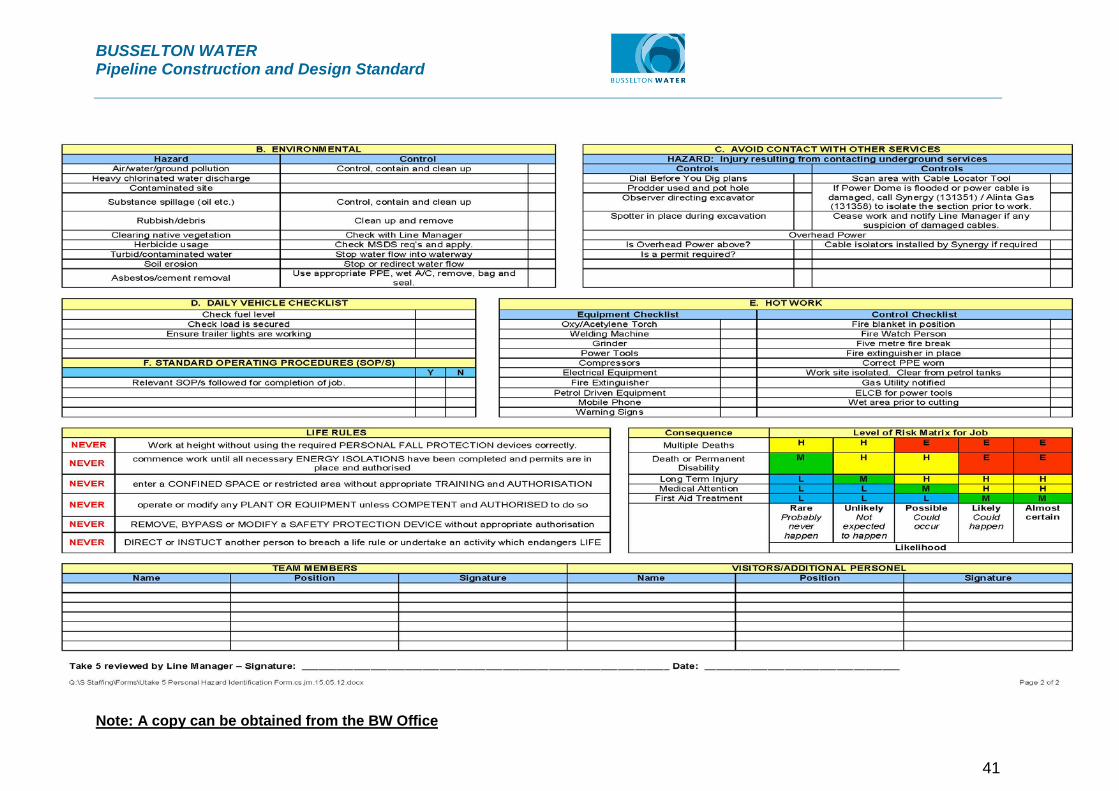
BUSSELTON WATER Pipeline Construction and Design Standard
41
Note: A copy can be obtained from the BW Office

BUSSELTON WATER Pipeline Construction and Design Standard
42
Attachment 1
IMPORTANT NOTICE REGARDING
YOUR WATER SERVICE
Dear Valued Customer
Please be advised that Busselton Water will be undertaking mains maintenance on DATE.
Water will be turned off from approximately TIME in the following areas:
LOCATIONS
Maintenance can in some instances causes water to look discoloured, this doesn’t usually last. If you do experience this please call us on 9781 0500.
Busselton Water regrets any inconvenience this may cause and seeks your tolerance in this matter.
For further information please contact Busselton Water on 9781 0500.
Yours faithfully
(for) Chris Elliott CHIEF EXECUTIVE OFFICER

BUSSELTON WATER Pipeline Construction and Design Standard
43
Attachment 2

PLAN - 90° BENDS
PLAN - TEES
BLANK ENDS
FSL
11.25° TO 45° BENDS
FSL
DIAMETER
NOMINAL
FITTING
TYPE OF
L (mm)
LENGTH
D (mm)
DEPTH
W (mm)
WIDTH
300
L (mm)
LENGTH
D (mm)
DEPTH
W (mm)
WIDTH
1550
2150
1200
600
300
750
750
750
750
750
550
700
450
350
350
L (mm)
LENGTH
D (mm)
DEPTH
W (mm)
WIDTH
800
1100
600
300
300
750
750
750
750
750
400
500
350
350
350
ALLOWABLE FOUNDATION BEARING PRESSURE**
50 kPa 100 kPa 200 kPa
DIAMETER
NOMINAL
FITTING
TYPE OF
L (mm)
LENGTH
D (mm)
DEPTH
W (mm)
WIDTH
375
L (mm)
LENGTH
D (mm)
DEPTH
W (mm)
WIDTH
L (mm)
LENGTH
D (mm)
DEPTH
W (mm)
WIDTH
1050
1500
800
450
300
850
850
850
850
850
500
650
450
400
400
ALLOWABLE FOUNDATION BEARING PRESSURE**
50 kPa 100 kPa 200 kPa
END OR TEE *
90°
45°
22.5°
11.25°
L
W
20
-
1
MEMBRANE
POLYETHYLENE
L
W20
SECTION 1
-SCALE : N.T.S.
PIP
E C
OVE
R
W20
50 MIN.
D
200
MIN.
200
SECTION 2
-SCALE : N.T.S.MEMBRANE
POLYETHYLENE
MEMBRANE
POLYETHYLENE
W
D
200
50 MIN. COMPACTED FILL
UNDISTURBED SOIL OR WELL
CONCRETE POURED AGAINST
-
1
-
2
L
W
-
1
MEMBRANE
POLYETHYLENE
L
WATER
BUSSELTON
BW-84-3 A
M B
WATER RETICULATION
STANDARD DRAWINGS
CONCRETE THRUST SUPPORTS - DN300-375
BEND, TEES & BLANK ENDS - PVC & DI PIPELINES
SHOWN.
PIPE LINE JOINTS NOT BE COMPLETELY ENCASED IN CONCRETE. 180 DEGREE MAXIMUM ENCASEMENT AS 9.
THRUST BLOCK CONCRETE CHARACTERISTIC COMPRESSIVE STRENGTH TO BE MINIMUM 25 MPa.8.
THE OUTMOST FACE OF THE BLOCK.
THRUST BLOCKS GREATER THAN 2000mm IN LENGTH TO HAVE SL81 MESH PLACED WITH 50mm COVER TO 7.
WRAP POLYETHYLENE MEMBRANE AROUND PIPE AND FITTING FOR PROTECTION.6.
UNCOMPACTED FILL, SPECIALIST GEOTECHNICAL ADVICE IS TO BE SORT.
WHERE INSITU MATERIAL CONSISTS OF VERY SOFT/SOFT/FIRM CLAY, LOOSE CLEAN SAND OR 5.
COMPACTED TO 95% MDD IN LAYERS NOT EXCEEDING 300mm.
WHERE TRENCH REQUIRES BACKFILL, FILL MATERIAL TO BE WELL GRADED CLEAN GRANULAR FILL 4.
MAXIMUM PIPE TEST PRESSURE TO BE 1200 kPa (120m).3.
ALL PIPE WORK AND FITTINGS TO BE IN ACCORDANCE WITH AS1477 AND AS4041.2.
MINIMUM PIPE COVER TO BE 600mm.1.
GENERAL NOTES:
HATCHED THRUST BLOCK DIMENSIONS ARE NOT RECOMMENDED. SPECIALIST GEOTECHNICAL ADVICE SHOULD BE SORT TO INCREASE FOUNDATION BEARING RESISTANCE.
ALLOWABLE INSITU MATERIAL FOUNDATION PRESSURES TO BE DETERMINED IN ACCORDANCE WITH WSA GUIDELINES. REFER TO WAT-1200.
THRUST BLOCK DIMENSIONS TO BE SIZED FOR BRANCH PIPE DIAMETER.
NOTE:
END OR TEE *
90°
45°
22.5°
11.25°
(REFER TO NOTE 7)
F81 MESH WITH 50 COVER
BUSSELTON WA 6280
PO BOX 57
PHONE: (08) 97810 500
RECOMMENDED
REC
APPROVED
APP
DRN
DATE
DES CKD
SIZE
SHEET
ORIGINAL
ISSUECAD
MF
PLANJOB NoFILEA3
1050
**
*
- -
W20
W20
1650
850
850
850
550
400
4200
5900
3200
850
850
850
1050
1850
800
2100
1600
850
450
850
850
850
850
700
600
400
400
2950 850 950
3050
4300
750
750
750
950
2350
1200
600
750
750
750
600
400
350
NOTE 4
COMPACTED FILL. REFER TO
UNDISTURBED SOIL OR WELL
CONCRETE POURED AGAINST
PRELIMINARY

DIAMETER
NOMINAL
FITTING
TYPE OF
L (mm)
LENGTH
D (mm)
DEPTH
W (mm)
WIDTH
200
1650
2350
1250
650
350
650
650
650
650
650
500
600
400
300
300
L (mm)
LENGTH
D (mm)
DEPTH
W (mm)
WIDTH
850
1200
650
350
300
650
650
650
650
650
350
450
300
300
300
L (mm)
LENGTH
D (mm)
DEPTH
W (mm)
WIDTH
450
600
350
300
300
650
650
650
650
650
300
350
300
300
300
ALLOWABLE FOUNDATION BEARING PRESSURE**
50 kPa 100 kPa 200 kPa
END OR TEE *
90°
45°
22.5°
11.25°
DIAMETER
NOMINAL
FITTING
TYPE OF
L (mm)
LENGTH
D (mm)
DEPTH
W (mm)
WIDTH
250
L (mm)
LENGTH
D (mm)
DEPTH
W (mm)
WIDTH
1150
1600
900
450
300
700
700
700
700
700
450
550
400
300
300
L (mm)
LENGTH
D (mm)
DEPTH
W (mm)
WIDTH
600
800
450
300
300
700
700
700
700
700
350
400
300
300
300
ALLOWABLE FOUNDATION BEARING PRESSURE**
50 kPa 100 kPa 200 kPa
END OR TEE *
90°
45°
22.5°
11.25°
PLAN - TEES
BLANK ENDS
FSL
11.25° TO 45° BENDS
FSL
PLAN - 90° BENDS
-
1
L
W
W
20
-
1
L
W
20
MEMBRANE
POLYETHYLENE
MEMBRANE
POLYETHYLENE
SECTION 1
-SCALE : N.T.S.
MEMBRANE
POLYETHYLENE
D
W20
PIP
E C
OVE
R
200
50 MIN.
200
MIN.
200
50 MIN.
W
D
MEMBRANE
POLYETHYLENE
L
SECTION 2
-SCALE : N.T.S.
-
1
-
2
L
W
WATER
BUSSELTON
BW-84-2 A
M B
WATER RETICULATION
STANDARD DRAWINGS
CONCRETE THRUST SUPPORTS - DN200-250
BEND, TEES & BLANK ENDS - PVC & DI PIPELINES
SHOWN.
PIPE LINE JOINTS NOT BE COMPLETELY ENCASED IN CONCRETE. 180 DEGREE MAXIMUM ENCASEMENT AS 9.
THRUST BLOCK CONCRETE CHARACTERISTIC COMPRESSIVE STRENGTH TO BE MINIMUM 25 MPa.8.
THE OUTMOST FACE OF THE BLOCK.
THRUST BLOCKS GREATER THAN 2000mm IN LENGTH TO HAVE SL81 MESH PLACED WITH 50mm COVER TO 7.
WRAP POLYETHYLENE MEMBRANE AROUND PIPE AND FITTING FOR PROTECTION.6.
UNCOMPACTED FILL, SPECIALIST GEOTECHNICAL ADVICE IS TO BE SORT.
WHERE INSITU MATERIAL CONSISTS OF VERY SOFT/SOFT/FIRM CLAY, LOOSE CLEAN SAND OR 5.
COMPACTED TO 95% MDD IN LAYERS NOT EXCEEDING 300mm.
WHERE TRENCH REQUIRES BACKFILL, FILL MATERIAL TO BE WELL GRADED CLEAN GRANULAR FILL 4.
MAXIMUM PIPE TEST PRESSURE TO BE 1200 kPa (120m).3.
ALL PIPE WORK AND FITTINGS TO BE IN ACCORDANCE WITH AS1477 AND AS4041.2.
MINIMUM PIPE COVER TO BE 600mm.1.
GENERAL NOTES:
COVER (REFER NOTE 7)
F81 MESH WITH 50
20
BUSSELTON WA 6280
PO BOX 57
PHONE: (08) 97810 500
RECOMMENDED
REC
APPROVED
APP
ORIGINAL
SHEET
SIZE
MF
ISSUECADPLANJOB NoFILE
DES CKD
DATE
DRN
A3
HATCHED THRUST BLOCK DIMENSIONS ARE NOT RECOMMENDED. SPECIALIST GEOTECHNICAL ADVICE SHOULD BE SORT TO INCREASE FOUNDATION BEARING RESISTANCE.
ALLOWABLE INSITU MATERIAL FOUNDATION PRESSURES TO BE DETERMINED IN ACCORDANCE WITH WSA GUIDELINES. REFER TO WAT-1200.
THRUST BLOCK DIMENSIONS TO BE SIZED FOR BRANCH PIPE DIAMETER.
NOTE:
1050
**
*
-
W
2250
1800
900
450
700
700
700
700
550
500
350
300
3150 700 750
NOTE 4
COMPACTED FILL. REFER TO
UNDISTURBED SOIL OR WELL
CONCRETE POURED AGAINST
FI/A9 BUSSELTON WATER
31/01/2012
CONSTRUCTION ISSUE
ENGINEERSGRIEVE
WOOD AND
31/01/2012
31/01/2012

PLAN - 90° BENDS
PLAN - TEES
BLANK ENDS
FSL FSL
11.25° TO 45° BENDS
DIAMETER
NOMINAL
FITTING
TYPE OF
L (mm)
LENGTH
D (mm)
DEPTH
W (mm)
WIDTH
100
550
800
450
300
300
550
550
550
550
550
300
400
300
300
300
L (mm)
LENGTH
D (mm)
DEPTH
W (mm)
WIDTH
300
400
300
300
300
550
550
550
550
550
300
300
300
300
300
L (mm)
LENGTH
D (mm)
DEPTH
W (mm)
WIDTH
300
300
300
300
300
550
550
550
550
550
300
300
300
300
300
ALLOWABLE FOUNDATION BEARING PRESSURE**
50 kPa 100 kPa 200 kPa
END OR TEE *
90°
45°
22.5°
11.25°
DIAMETER
NOMINAL
FITTING
TYPE OF
L (mm)
LENGTH
D (mm)
DEPTH
W (mm)
WIDTH
150
1050
1500
800
400
300
600
600
600
600
600
350
400
300
300
300
L (mm)
LENGTH
D (mm)
DEPTH
W (mm)
WIDTH
550
750
400
300
300
600
600
600
600
600
300
300
300
300
300
L (mm)
LENGTH
D (mm)
DEPTH
W (mm)
WIDTH
300
400
300
300
300
600
600
600
600
600
300
300
300
300
300
ALLOWABLE FOUNDATION BEARING PRESSURE**
50 kPa 100 kPa 200 kPa
END OR TEE *
90°
45°
22.5°
11.25°
-
1
SECTION 1
-SCALE : N.T.S.
W20
D
200
200
50
MIN.
MIN.
W
50
200
D
SECTION 2
-SCALE : N.T.S.
-
2
L
W
L
20
W
L
W
20
W
L
-
1
MEMBRANE
POLYETHYLENE
MEMBRANE
POLYETHYLENE
MEMBRANE
POLYETHYLENE
WATER
BUSSELTON
BW-84-1 A
M B
WATER RETICULATION
STANDARD DRAWINGS
CONCRETE THRUST SUPPORTS - DN100-150
BEND, TEES & BLANK ENDS - PVC & DI PIPELINES
-
1
SHOWN.
PIPE LINE JOINTS NOT BE COMPLETELY ENCASED IN CONCRETE. 180 DEGREE MAXIMUM ENCASEMENT AS 9.
THRUST BLOCK CONCRETE CHARACTERISTIC COMPRESSIVE STRENGTH TO BE MINIMUM 25 MPa.8.
THE OUTMOST FACE OF THE BLOCK.
THRUST BLOCKS GREATER THAN 2000mm IN LENGTH TO HAVE SL81 MESH PLACED WITH 50mm COVER TO 7.
WRAP POLYETHYLENE MEMBRANE AROUND PIPE AND FITTING FOR PROTECTION.6.
UNCOMPACTED FILL, SPECIALIST GEOTECHNICAL ADVICE IS TO BE SORT.
WHERE INSITU MATERIAL CONSISTS OF VERY SOFT/SOFT/FIRM CLAY, LOOSE CLEAN SAND OR 5.
COMPACTED TO 95% MDD IN LAYERS NOT EXCEEDING 300mm.
WHERE TRENCH REQUIRES BACKFILL, FILL MATERIAL TO BE WELL GRADED CLEAN GRANULAR FILL 4.
MAXIMUM PIPE TEST PRESSURE TO BE 1200 kPa (120m).3.
ALL PIPE WORK AND FITTINGS TO BE IN ACCORDANCE WITH AS1477 AND AS4041.2.
MINIMUM PIPE COVER TO BE 600mm.1.
GENERAL NOTES:
BUSSELTON WA 6280
PO BOX 57
PHONE: (08) 97810 500
A3
ORIGINAL
SHEET
SIZE
MF
ISSUECADPLANJOB NoFILE
RECOMMENDED
REC
APPROVED
APP
DES CKD
DATE
DRN
HATCHED THRUST BLOCK DIMENSIONS ARE NOT RECOMMENDED. SPECIALIST GEOTECHNICAL ADVICE SHOULD BE SORT TO INCREASE FOUNDATION BEARING RESISTANCE.
ALLOWABLE INSITU MATERIAL FOUNDATION PRESSURES TO BE DETERMINED IN ACCORDANCE WITH WSA GUIDELINES. REFER TO WAT-1200.
THRUST BLOCK DIMENSIONS TO BE SIZED FOR BRANCH PIPE DIAMETER.
NOTE:
1050
**
*
-
PIP
E C
OVE
R
MEMBRANE
POLYETHYLENE
w20
NOTE 4
COMPACTED FILL. REFER TO
UNDISTURBED SOIL OR WELL
CONCRETE POURED AGAINST
FI/A9 BUSSELTON WATER
31/01/2012
CONSTRUCTION ISSUE
ENGINEERSGRIEVE
WOOD AND
31/01/2012
31/01/2012

BUSSELTON WATER Pipeline Construction and Design Standard
44
Attachment 3
DEPARTMENT OF FIRE AND EMERGENCY SERVICES
STANDARD
FOR
HYDRANT INSTALLATION
March 2013

BUSSELTON WATER Pipeline Construction and Design Standard
45
Introduction Fire hydrants are integral to effective fire and emergency management. The
Department of Fire and Emergency Service (DFES) is committed to monitoring
contemporary emergency water service delivery measures and reviewing the
suitability of these standard hydrant conditions as required. DFES has identified the
following design standard requirements for hydrants connected to all water utility
water mains.
DFES Hydrant Standard conditions have been developed from the Water Corporation
Design Standard 63 for water service infrastructure. DFESA is working with the
Aqwest and Busselton Water providers to include the following standard hydrant
conditions in their infrastructure design requirements.
Specifications
Hydrants
Hydrants shall be WA pattern 100mm screw-down type with integral ‘yoke’ SPS 292
with built-in isolation valve and installed only on DN100mm or larger pipes. Hydrants
shall be located;
• so that the maximum distance between a hydrant and the rear of a building
envelope, (or in the absence of a building envelope the rear of the lot) shall be
120 m and the hydrants shall be no more than 200 m (+ / - 10m) apart;
• a maximum of 100 m (+ / - 10 m) spacing in industrial and commercial areas;
hydrants in these areas should conform to Building Classification 2 – 9c as per
the Building Code of Australia;
• hydrant spacing in rural residential areas where minimum site areas per
dwelling is 10,000 m2 (1ha), a maximum 400 m (+ / - 10 m) hydrant spacing be
applied. If area is further subdivided to land parcels less than 1ha, then the
residential standard (200m (+ / - 10 m) ) is to be applied;
• ideally hydrants will be located in proximity to a boundary to allow it to be
readily located
• Hydrants shall be located centrally only when driveways create a problem;
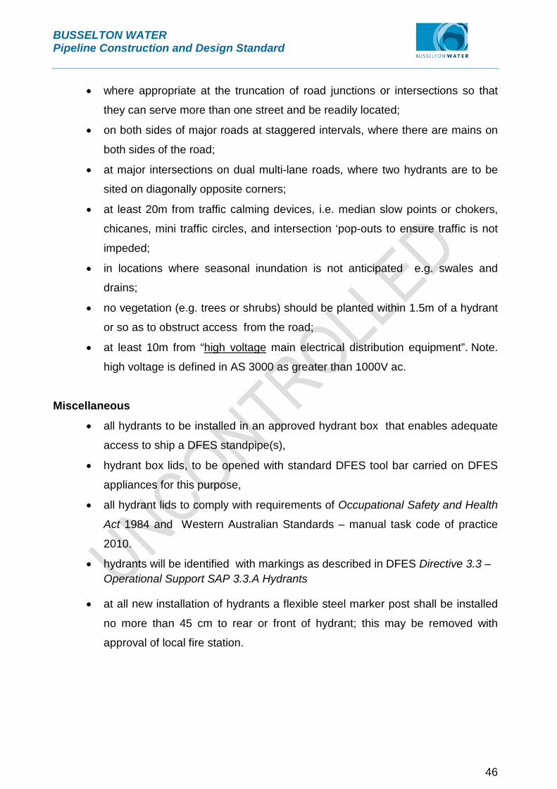
BUSSELTON WATER Pipeline Construction and Design Standard
46
• where appropriate at the truncation of road junctions or intersections so that
they can serve more than one street and be readily located;
• on both sides of major roads at staggered intervals, where there are mains on
both sides of the road;
• at major intersections on dual multi-lane roads, where two hydrants are to be
sited on diagonally opposite corners;
• at least 20m from traffic calming devices, i.e. median slow points or chokers,
chicanes, mini traffic circles, and intersection ‘pop-outs to ensure traffic is not
impeded;
• in locations where seasonal inundation is not anticipated e.g. swales and
drains;
• no vegetation (e.g. trees or shrubs) should be planted within 1.5m of a hydrant
or so as to obstruct access from the road;
• at least 10m from “high voltage main electrical distribution equipment”. Note.
high voltage is defined in AS 3000 as greater than 1000V ac.
Miscellaneous
• all hydrants to be installed in an approved hydrant box that enables adequate
access to ship a DFES standpipe(s),
• hydrant box lids, to be opened with standard DFES tool bar carried on DFES
appliances for this purpose,
• all hydrant lids to comply with requirements of Occupational Safety and Health
Act 1984 and Western Australian Standards – manual task code of practice
2010.
• hydrants will be identified with markings as described in DFES Directive 3.3 – Operational Support SAP 3.3.A Hydrants
• at all new installation of hydrants a flexible steel marker post shall be installed
no more than 45 cm to rear or front of hydrant; this may be removed with
approval of local fire station.