Pipe Rehabilitation by Trenchless · Why Pipe Rehabilitation ... • Pits excavation ... grout and...
90
Pipe Rehabilitation by Trenchless Pipe Rehabilitation by Trenchless Technology Introduction Introduction Update: 13 April 2011 1
Transcript of Pipe Rehabilitation by Trenchless · Why Pipe Rehabilitation ... • Pits excavation ... grout and...

Pipe Rehabilitation by TrenchlessPipe Rehabilitation by Trenchless Technology
IntroductionIntroduction
Update: 13 April 2011 1

Why Pipe Rehabilitation (PR)
• HK supplies portable and salt water through a water mains of more than 7200km
• 45% of the underground system are built 3045% of the underground system are built 30 years ago approaching the end their service lifelife
• New service life/ design life is ≥ 50 years
Update: 13 April 2011 2

Four stages to solve pipe problemsg p p p
Determine the standard of performance needed
Identify the pipe problems via various surveys
According to the problems, determine the rehabilitating solution
Implement the rehabilitation and assess the effectImplement the rehabilitation and assess the effect
(continued)
Update: 13 April 2011 3

Strategies to Solve Pipe ProblemsUsing 4R Strategy
Right Skilled Persons – Skilled persons or Utilities Specialists can identify the pipe problem(s) by various survey methodspipe problem(s) by various survey methods i.e. CCTV, Pipe Condition Survey, Water Leakage Investigation Method(s) ‐ Determine required standards
Right Planning/ ‐ Based on the problem defined and required standards;Preparation Plan/Prepare the best rehabilitation method to
overcome itRight Equipment ‐ Implement the determined rehabilitation works in aRight Equipment Implement the determined rehabilitation works in a
most efficient/effective wayRight Price ‐ Tender Price should include all 3R mentioned above
‐ Adopt the right planning/preparation, right equipment then implementation by right skilledpersons/Utilities Specialists, the determined pipe rehabilitation works could be completed on time, efficient and within cost budget
Update: 13 April 2011 4
efficient and within cost budget

Water Leakage Detection
Mechanical Listening Device LNCMechanical Listening Device
LNC
Update: 13 April 2011 5
LNC

CCTV Survey
Update: 13 April 2011 6

F l i blFour stages to solve pipe problems
Update: 13 April 2011 7

Why Trenchless Technology (TT)
• PR can be divided into pipe trench digging and TTTT
• Advantages of TT over pipe trench digging:– Less open digs, less disturbance to traffic and publicpublic
– More Economic
F t i t ll ti– Faster installation
Update: 13 April 2011 8

Types of TT• Two basic types:
– If the pipe has serious structural problem → p p p →trenchless construction methods (TCM)
– TCM: install a new pipeTCM: install a new pipe
– If the pipe’s problem is structural but non‐crucial → trenchless renewal methods (TRM)→ trenchless renewal methods (TRM)
– TRM: renew the old pipe
(Continued)
Update: 13 April 2011 9
Types of TTWe will only focus on 3 trenchless renewal methods/ lining methods:Cured‐in‐place pipe (CIPP)Sliplining (SL)Close‐fit pipe (CFP)
Update: 13 April 2011 10

Applications of TT
• Sanitary sewer and waste pipelines• Potable water, drainage and irrigation pipelines• Gas transmission pipelines• Industrial process pipelines• Electrical conduits and marine vessel pipes
(Continued)
Update: 13 April 2011 11

Applications of TTApplications of TT
• Oilfield and containment pipelinesp p
• Nuclear facility cooling systems
• Force mains and slurry pipelines
• High‐rise building utilities (seldom use in H.K.)High rise building utilities (seldom use in H.K.)
Update: 13 April 2011 12

Limitations of TT• Size: 100 – 2800 mm in dia., however it is not cost effective for bigger size due to cost of materialseffective for bigger size due to cost of materials
• Pull in area required for Slip Lining
• Scaffold tower required for water curing processScaffold tower required for water curing process.
• Diversion required for most systems.
(Continued)
Update: 13 April 2011 13

Limitations of TTLimitations of TT
• Temporary Traffic Arrangement required for most• Temporary Traffic Arrangement required for most systems especially those using water or steam for curing process.g p
• Polyester Resin may be adversely affected by water until they have cured.
Update: 13 April 2011 14

Rehabilitation Design Considerations• Type of pipe problem• Pressure or gravity pipe
l b l d• Lining material to be applied• Pipe characteristics:
– Pipe diameter– Pipe diameter– Pipe shape– Pipeline with or without lateral connectionsp– Straight or bended pipe– Varying or uniform pipe cross‐sections, etc.
(Continued)
Update: 13 April 2011 15

Rehabilitation Design ConsiderationsRehabilitation Design Considerations
• Lining installation length• Type of fluid carried by the pipe• Design life• Cost, etc.
Update: 13 April 2011 16
Polymeric materials for the liner of PR
• Common materials for liner:– Polyethylene (PE)
– Polyvinylchloride (PVC)– Polyvinylchloride (PVC)
– Glass reinforced plastic (GRP) (also named as fib l )fiberglass)
– Polyester resin
– Polyurethane (PU)
– Etc.tc.
Update: 13 April 2011 17

Common Preparations Before Insertion of liner for Different Linings
• Pits excavation & Preparation (the launch and reception pits or manholes for the insertion of thereception pits or manholes for the insertion of the liner)
P i t ll ti l i• Pre‐installation cleaning
• Followed by a CCTV inspection
(Continued)(Continued)
Update: 13 April 2011 18

Common Preparations Before Insertion of liner for Different Linings
• The openings or connections in the middle of the i h ld b l d d b i ipipe should be closed and not be in operation
• Bypassing the existing flow/over‐pumping if too long water suspension period or too large flow discharge rate
Update: 13 April 2011 19

Launching & Receiving Pit / ManholeLaunching & Receiving Pit / Manhole
• The entry pit or manhole is the highest point y p g pin the pipeline to be renovated. This is the position of the support truckposition of the support truck.
• The winch (if necessary) is positioned at the reception manhole or pit to pull in the pipe.
(Continued)
Update: 13 April 2011 20

Launching & Receiving Pit / ManholeLaunching & Receiving Pit / Manhole
• The launching pit should be constructed to g pallow enough space for reconnecting lining into the available networkinto the available network.
• The receiving pit should be constructed to allow enough space for winch accommodation and pipe reversion.p p
Update: 13 April 2011 21

Pre‐installation Cleaningg• To remove all internal dirt, tuberculation and debris to promote bond between liner or grout and the inner wall of the existing pipeg g p p
• High pressure water jetting is usually used
h f bl h• For the case of portable water pipe, the cleaning equipment need to be first sterilized
Update: 13 April 2011 22

CCTV InspectionCCTV Inspection
• After cleaning the pipeline for lining• After cleaning, the pipeline for lining undergoes a CCTV inspection and a video is takentaken
(Continued)
Update: 13 April 2011 23

CCTV InspectionCCTV Inspection
• To check and note:• To check and note:– The pipe material & condition
h l l f l l– The level of cleanliness– Location of all existing bends and defects– Location of any openings or connections in the middle of the pipe
Update: 13 April 2011 24

Lateral openings and connectionsLateral openings and connections
Update: 13 April 2011 25

Pipe Rehabilitation by TrenchlessPipe Rehabilitation by Trenchless Technologygy
Cured‐in‐pipe (CIPP)Cured in pipe (CIPP)
Update: 13 April 2011 26

CIPP ‐ Applicationpp• Applied to pipe diameter of 75mm to 2500mm
• For both structural and non‐structural pipe problem
• Used in a wide range of pipes: sewers, portable g p p , pwater pipes, gas pipes, etc.
• More common for gravity pipe than high pressureMore common for gravity pipe than high pressure pipe
• However in HK commonly for sewers and cooling• However, in HK, commonly for sewers and cooling mains
Update: 13 April 2011 27

CIPP ‐Main Component of LinerCIPP Main Component of Liner• Main component of CIPP (liner):
– a thermosetting resin system – and a flexible fabric tube (for carrying and supporting the resins till it is installed and cured)
– Impermeable coating(not a must)
(Continued)
Update: 13 April 2011 28

CIPP ‐Main Component of Liner• 3 types of resin:
Unsaturated polyester–Unsaturated polyester–Vinyl ester– Epoxy
• Material for fabric tube can be:–Nonwoven–WovenWoven
(Continued)(Continued)
Update: 13 April 2011 29

CIPP ‐Main Component of LinerCIPP Main Component of Liner
• Impermeable coatings are commonly used on the exterior, or interior, or both of the tube to , ,protect the resin during installation
Update: 13 April 2011 30

CIPP ‐ Key Steps of Liner Installation1. Bypass the existing flow and clean the existing
pipe by pipe jettingp p y p p j g2. CCTV inspection3 Impregnation of the CIPP liner3. Impregnation of the CIPP liner4. Liner insertion by water inversion or compressed
air inversion or winch cable pulling methodair inversion or winch cable pulling method5. Curing by hot water or steam6 Cool down reconnect later connections and6. Cool down, reconnect later connections and
CCTV inspection
Update: 13 April 2011 31

CIPP ‐ Preparation of Liner• Steps of preparing CIPP liner:
– Cut the liner to correct length– The resin is mixed with catalysts and retarder by electrical stirring equipment until thoroughly mixedstirring equipment until thoroughly mixed
– Impregnation: pump in the resin mix into the fabric tube. – The resin mix is spread evenly throughout by usingThe resin mix is spread evenly throughout by using calibration rollers
(Continued)
Update: 13 April 2011 32

CIPP Preparation of LinerCIPP ‐ Preparation of Liner
• Remarks:– All air is vacuumed out of the fabric tube as this allow resin to soak thoroughly into the tubeto soak thoroughly into the tube
– Impermeable coatings or other protective membrane must be applied as a pre‐liner to protect the resin if CCTV shows pp p pinfiltration occur
(Continued)
Update: 13 April 2011 33

CIPP ‐ Preparation of Liner
Cut the liner to correct length- Cut the liner to correct length - mix the resin with catalysts by electrical stirring equipment. - After that, pump the resin mix into the fabric tube
Update: 13 April 2011 34

CIPP ‐ Preparation of Linerp
Calibration roller滾軸 Resin膠漿Resin膠漿
Update: 13 April 2011 35

CIPP ‐ Preparation of LinerCIPP Preparation of Liner
Liner produced完成的襯墊 catalyst摧化劑
Update: 13 April 2011 36

CIPP ‐ Installation & Curing Methodsg
• 3 different installation methods to insert the liner into the existing pipe:– Water inversion
– Compressed air inversion
– Winch pulling method– Winch pulling method
(Continued)(Continued)
Update: 13 April 2011 37
CIPP ‐ Installation & Curing Methods
• 3 curing methods to cure liner with existing pipe:H t t i– Hot water curing
– Steam curing
– UV light curing (less common in HK)
Update: 13 April 2011 38

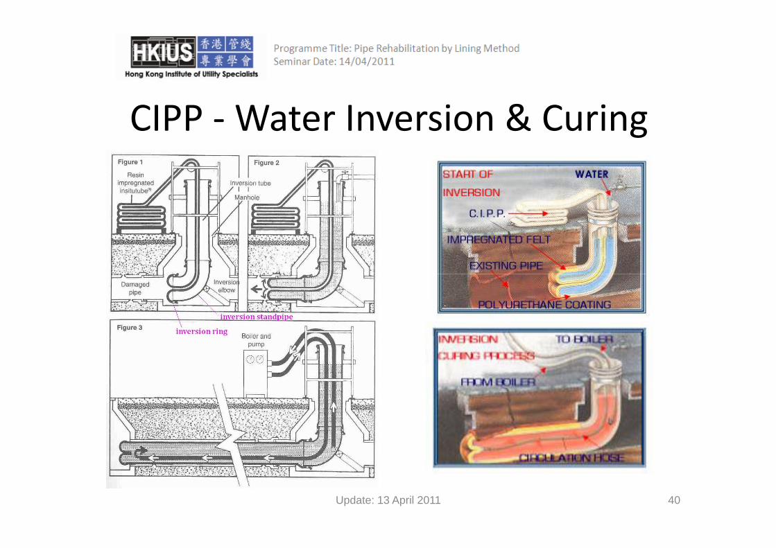
CIPP ‐Water Inversion & Curing• Insertion by water inversion :
1. The end of liner is turned inside out and clamped around an i i i f i t b kinversion ring forming a turnback
2. The turnback head around the ring is fitted to an inversion standpipe (also named as inversion tube) from the top of it
3. The standpipe with turnback is connected to the existing pipe4. Water is then introduced into the standpipe and therefore
onto the turnback5. Liner starts to turn inside out along the existing pipe and
against the pipe wall6 A cable is attached to the end of the liner to guide the6. A cable is attached to the end of the liner to guide the
inversion
(Continued)(Continued)
Update: 13 April 2011 39
CIPP ‐Water Inversion & Curing
Update: 13 April 2011 40

CIPP ‐Water Inversion & Curing• For water inversion, only hot water curing can be applied:– The water in liner is circulated to a water filtration unit and then mobile water boiler by a water circulation pump systemp p y
– Water is heated by the boiler to the curing temperature (e.g. 65°C to 90°C for epoxy resin) gradually to achieve a controlled curingg adua y to ac e e a co t o ed cu g
– Hot water circulates back to liner through a hose– Curing time (several hour usually) depends on:
Th f h b il• The power of the boiler• The length and diameter of the pipe to be cured
(Continued)
Update: 13 April 2011 41

CIPP ‐Water Inversion & CuringCIPP Water Inversion & Curing
Water Boiler & pumpWater Boiler & pump
Update: 13 April 2011 42

CIPP – compressed air Inversion & Curing• Insertion by compressed air inversion:
– The liner with resin is drawn into a reversing drumThe liner with resin is drawn into a reversing drum– The end of the liner is turned inside out and connected to the reversing flange on the outside of th dthe drum
– Reversion is by driving air into the turnback and air pressure force the liner forward along the wall of thepressure force the liner forward along the wall of the existing pipe
– A pulling cable is attached to the liner’s end to guide h i ithe inversion
(Continued)(Continued)
Update: 13 April 2011 43

CIPP – compressed air Inversion & Curingp g
d h• For compressed air inversion, hot water or steam curing can be applied
(Continued)(Continued)
Update: 13 April 2011 44

CIPP – compressed air Inversion & Curing
The liner with resin is put into the pipe.
A pulling cable is attached to the liner’s end to guide the inversion.
Update: 13 April 2011 45

CIPP – compressed air Inversion & Curing
I t ith Ai
Update: 13 April 2011 46
Invert with Air

CIPP – compressed air Inversion & Curing
Set appropriate air pressure for lining inversion
The end of the liner is turned inside out.
Update: 13 April 2011 47

CIPP – compressed air Inversion & Curing
Reversion Drum氣鼓 Reversion Drum氣鼓
Update: 13 April 2011 48

CIPP – compressed air Inversion & Curing
Steam Curing
Update: 13 April 2011 49

CIPP – compressed air Inversion & Curingp g
• For steam curing:• For steam curing:
– When liner is in place, the within pressure is l dreleased
– Then steam from a mini steam generator and through a compressor is circulated into the liner by pumping system with hose
Update: 13 April 2011 50
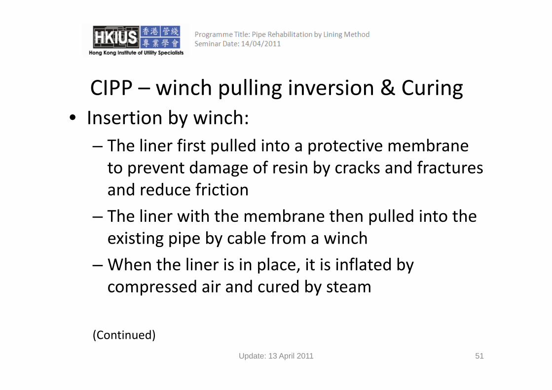
CIPP – winch pulling inversion & Curing• Insertion by winch:
– The liner first pulled into a protective membraneThe liner first pulled into a protective membrane to prevent damage of resin by cracks and fractures and reduce frictionand reduce friction
– The liner with the membrane then pulled into the existing pipe by cable from a winchexisting pipe by cable from a winch
– When the liner is in place, it is inflated by ompressed air and red b steamcompressed air and cured by steam
(Continued)
Update: 13 April 2011 51

CIPP – winch pulling inversion & Curing
Update: 13 April 2011 52

CIPP – final steps after curing• When curing ends, the pipe is cooled down and emptied
• Invert the calibration hose out of the lined pipe• The ends of the newly formed pipe are cut and y p ptrimmed
• For pipe with connections in the middle, dimples can be created at the connecting locations by the pressure during inversion and curing
(Continued)
Update: 13 April 2011 53

CIPP – final steps after curing• A special cutting device or robot with CCTV or man entry is employed to cut hole for lateralman entry is employed to cut hole for lateral connection if necessary
• A CCTV inspection is done to check the new• A CCTV inspection is done to check the new pipe being without visual defects
• Fill the annular gap with cement mortar• Fill the annular gap with cement mortar between the liner and the host pipe at the manholesmanholes.
Update: 13 April 2011 54
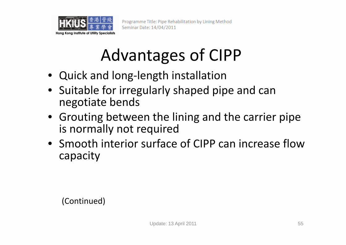
Advantages of CIPP• Quick and long‐length installation• Suitable for irregularly shaped pipe and can g y p p pnegotiate bends
• Grouting between the lining and the carrier pipe g g p pis normally not required
• Smooth interior surface of CIPP can increase flow capacity
(Continued)
Update: 13 April 2011 55

Advantages of CIPPAdvantages of CIPP• Bends or pipe deformation can be adapted though localized wrinkling may appear
• Small variation of pipe cross section can be• Small variation of pipe cross section can be adapted
• Laterals remade in sewer
Update: 13 April 2011 56

CIPP LimitationsCIPP ‐ Limitations• Full pumping needed in the installation• Full pumping needed in the installation• The existing flow must be bypassed during
installationinstallation• Limited pipe diameter application for
winched liningswinched linings
Update: 13 April 2011 57

Pipe Rehabilitation by TrenchlessPipe Rehabilitation by Trenchless TechnologygySliplining (SL)
Update: 13 April 2011 58

Sliplining ‐ ApplicationSliplining Application• A smaller pipe inserted into the existing pipe and the annular space between the 2 pipes is groutedgrouted
• Applied to pipe diameter of 20mm to 25002500mm
(Continued)
Update: 13 April 2011 59

Sliplining ApplicationSliplining ‐ Application
• For both structural and non structural prolem• For both structural and non‐structural prolem
• For both sewers and portable water pipes
• Owing to cost consideration, more common for pressure pipe than gravity pipefor pressure pipe than gravity pipe
Update: 13 April 2011 60

Sliplining
Update: 13 April 2011 61

Sliplining – Types of SlipliningSliplining – Types of Sliplining
• 2 types of sliplining: continuous and segmental• 2 types of sliplining: continuous and segmental• Continuous sliplining: segmental pipes are joined into a continuous piece of any length which is theninto a continuous piece of any length which is then slipped into the existing host pipe
(Continued)
Update: 13 April 2011 62

Sliplining – Types of Slipliningp g yp p g• Segmental sliplining:
Hi hl i il i li li i– Highly similar to continuous sliplining
– There are many short‐length segmental pipes with a flush sleeve jointsleeve joint
– They are connected at the launch pit and forced into the host pipe one by onehost pipe one by one
– Choosing which method depends on the pit size and its nearby area available, i.e. the temporary trafficnearby area available, i.e. the temporary traffic arrangement
(Continued)
Update: 13 April 2011 63

Sliplining – Types of SlipliningSliplining – Types of Sliplining
• Segmental method is applicable for diameters• Segmental method is applicable for diameters larger than 610mm
• For continuous sliplining, grouting may not be required while that for segmental sliplining isrequired while that for segmental sliplining is a must
Update: 13 April 2011 64

Sliplining ‐MaterialsSliplining Materials
• The following are more common ones:g– Polyethylene (PE)
Glassfibre reinforced pol ester (GRP)– Glassfibre reinforced polyester (GRP)
– PVC
Update: 13 April 2011 65

Sliplining – joining of Segmental Pipes• The segmental pipes can be joined by butt fusion, gasketed bell and spigot, or extrusion welding togasketed bell and spigot, or extrusion welding to form the long liner
• The joining method depends on the type of liner• The joining method depends on the type of liner material used. For instance, solid wall PE pipe is usually joined by butt fusion while PE profileusually joined by butt fusion while PE profile walled pipe is usually integral gasketed bell and spigot or extrusion weldingspigot or extrusion welding
(Continued)
Update: 13 April 2011 66

Sliplining – joining of Segmental Pipes
• The joining is done either above ground or in the launch pit If the launch pit is long enoughthe launch pit. If the launch pit is long enough to allow the liner pipe curve through the bends of the pit the joining is usually donebends of the pit, the joining is usually done above groundF l di t PE i f h t it• For large diameter PE pipes for a short pit, butt fusion in launch pit is usually applied
(Continued)
Update: 13 April 2011 67

Sliplining – joining of Segmental Pipes
• However, the installation rate is slower as time is needed for fusing pipe segments and coolingneeded for fusing pipe segments and cooling welds. Cooling time cannot be too short as that
k th t th f th i li d ican weaken the strength of the pipeline during installation and shorten the service life.
• The external beads formed due to welding on the pipe are removed by special tool prior to the p p y p pinsertion. All beads add to the friction between the existing and the new pipes during installation.g p p g
Update: 13 April 2011 68

Sliplining – Inversion Methodp g
• The liner are inserted by pushing or pulling orThe liner are inserted by pushing or pulling or both from a launch pit to a reception pit.
h ll ll• Pushing generally uses manually or hydraulically powered machines
(Continued)(Continued)
Update: 13 April 2011 69

Sliplining – Inversion Method
• If the liner pipe uses the bell and spigot• If the liner pipe uses the bell and spigot gasketed joint arrangement, the liner pipe must be inserted by pushing
• After insertion, there are connecting servicesAfter insertion, there are connecting services laterals, if there are any, and also grouting
Update: 13 April 2011 70

Sliplining – Installation Procedure• To show steps of sliplining, the installation of solid wall PE
pipe by continuous sliplining in a launch pit is stated as an lexample:
– Cleaning of host pipe and CCTV inspection– Segmental pipes joining by butt fusion welding in the launch pitg p p j g y g p– Cooling down the joined liner– Remove the external beads formed due to welding by special tool
prior to the insertionprior to the insertion– The jointed liner is pulled into the existing host pipe by the cable of
winch. After pulled for a distance, it goes to welding again, and then pulling againpulling again
– Grouting the space between the liner and the existing host pipe and reconnecting service laterals by excavation from outside
Update: 13 April 2011 71

Sliplining ‐ Advantages• Quick and simple to install
C t ff ti f i d i• Cost‐effective for pressurized pipes
• Segmental slipining may not require bypassing g p g y q yp gof the existing flow.
• It can be used to most types of pipes• It can be used to most types of pipes
• It has an independent structural integrity and is not reliant on the integrity of the host pipe
• It causes little disturbance to other utilities• It causes little disturbance to other utilities Update: 13 April 2011 72

Sliplining ‐ LimitationsSliplining Limitations
• Grouting is usually neededGrouting is usually needed
• The reduction of diameter of the original pipe f h b lafter rehabilitation
• With pressure pipelines, it is sometimesWith pressure pipelines, it is sometimes possible to increase the working pressure and thus compensate for the loss in flow capacitythus compensate for the loss in flow capacity.
Update: 13 April 2011 73

Pipe Rehabilitation by TrenchlessPipe Rehabilitation by Trenchless Technology
Close‐fit pipe (CFP)Close fit pipe (CFP)
Update: 13 April 2011 74

CFP ‐ Introduction
• Another name: Formed‐in place pipe (FIPP) lining
• In a CFP lining the liner’s outside diameter is• In a CFP lining, the liner s outside diameter is slightly larger than the inside diameter of the i i h iexisting host pipe
(Continued)
Update: 13 April 2011 75

CFP ‐ IntroductionCFP Introduction
• The cross section of the liner is temporarily• The cross section of the liner is temporarily deformed or reduced before insertion into the existing host pipe. The liner is later restored close to its original diameter, forming a close g gfit with the existing host pipe
Update: 13 April 2011 76

CFP – Types of CFP liningsCFP Types of CFP linings
f l• 3 types of CFP linings:– Deformed lining: cross section temporarily folded
– Rolldown: diameter reduction by mechanical method
– Swageling: diameter reduction by thermal method
(Continued)
Update: 13 April 2011 77

CFP – Types of CFP liningsCFP Types of CFP linings
• Remark• Remark– There are 2 types of swagelining: hot swagelining & cold
li iswagelining
– One difference between rolldown and swagelining is that after reducing the diameter the liner’s pipe wall becomesafter reducing the diameter, the liner s pipe wall becomes thicker in rolldown while that in swagelining remains the same
(Continued)
Update: 13 April 2011 78

CFP – Types of CFP lining• Mechanically folded pipe
Update: 13 April 2011 79

CFP – Types of CFP Lining
• Rolldown
Update: 13 April 2011 80

CFP – Installation Procedureh f h i ll i f i i d l• To show steps of CFP, the installation of compact pipe is stated as an example:
– Insertion: At the entrance pit, the drum with pipe is handled with the dedicated drum dispensing unit, the drum trailer. The winch to pull in the pipe is positioned at the reception pitis positioned at the reception pit.
– Heating: Saturated steam is feeded into the pipe to make pipe heat up and regain its original cross section.Expansion: When the pipe is sufficiently heated up steam is replaced by cold– Expansion: When the pipe is sufficiently heated up, steam is replaced by cold compressed air. Expansion takes place just after switching from steam to compressed air. The air pressure is set high enough to enable the pipe to radially expand, thus achieving a close‐fit with the interior of the existing y p g gpipeline.
– Cooling: Cooling down with air takes place simply by keeping the pressure on. The cooling phase ends when ambient temperature has been reached.
– Fixation: Fixation of pipe ends by means of electrofusion is needed to prevent longitudinal shrinkage during or prior to reconnection.
– Reconnection: Reconnection to the existing pipeline can be achieved by means f f i h i d h i l bl h iof fusion techniques and mechanical assembly techniques
Update: 13 April 2011 81

CFP ‐ Advantages• Little reduction in diameter of pipe after lining• Little loss in flow capacityLittle loss in flow capacity• It is rapid and causes little disturbance to other utilitiesutilities
• Improved hydraulic performance compared to the host pipethe host pipe
• No grouting required• The liner can be used in host pipes with bends up to 45°
Update: 13 April 2011 82

CFP ‐ Limitations• A large working area is required to lay the butt fused liner before diameter reduction &butt‐fused liner before diameter reduction & insertion
• Bypassing the existing pipe’s flow during installation is requiredinstallation is required
• Not suitable for rehabilitating the existing pipe i h i iwith varying cross‐sections
Update: 13 April 2011 83
Pipe Rehabilitation by TrenchlessPipe Rehabilitation by Trenchless Technologygy
Quality ControlQuality Control
Update: 13 April 2011 84

Project Quality PlanPrepare Project Quality Plan by qualified staff prior to lining works commencement i.e. MHKIUS or OMHKIUS in PR Division;
Monitor right steps, right skilled staff, right equipment are deployed for carrying out the lining works;carrying out the lining works;
Qualified Project Manager (MHKIUS or OMHKIUS in PR Division) should use quality control technique namely Plan – Do – Check – Act to ensure h d i d PQP i i l d d d d i dthe determined PQP is implemented and updated as required;
Final inspection/checking to endorse the completed lining works achieve the required standards/performance;q /p ;
Update: 13 April 2011 85

Quality Control
• Proper records to ensure quality of lining work
– Daily record of work (equipment, skilled staff, progress, safety issues)
– Size and material of the existing host pipeg p p
– Details of the lining including outside diameter, wall thickness, material
– Result of initial and final color CCTV inspection
R ti it / i i f i t l t t lt (CIPP l )– Reactivity/ mixing of resin control test result (CIPP only)
– Temperature (°C) of lining at installation(CIPP only)– Temperature (°C) of lining during curing and upon completion of rehabilitation
(CIPP only)
– Etc.
Update: 13 April 2011 86

4R Strategy4R Strategy
Right Skilled Person – Implement the lining works comply with requiredRight Skilled Person Implement the lining works comply with required PQP stipulated requirements
Right Planning/ ‐ Qualified staff (MHKIUS or OMHKIUS in PR Division) Preparation prepare the best lining method in terms of timePreparation prepare the best lining method in terms of time,
cost, quality namely Iron TriangleRight Equipment ‐ Adopted to complete the lining works to achieve
stipulated standards and performanceRight Price ‐ Tender Price should be estimated using 3R criteria
as mentioned above‐ Final goal is achieved in terms of “On Time Completion, Within Budget Cost, Comply Quality Standards”
Update: 13 April 2011 87

Pipe Rehabilitation by Trenchless Technology
Conclusion
Update: 13 April 2011 88

Conclusionshl h i i i d i• Trenchless techniques are gaining ground in
capabilities & use.• Successful use of trenchless requires careful consideration of its strengths & weaknesses.g
• Ground, site and project conditions should be considered in the use of trenchlessconsidered in the use of trenchless technologies.F t hl t h l i f l l i i• For trenchless technologies careful planning is required.
Update: 13 April 2011 89

Reference
• http://www.uti.hk
• http://www.gastechnology.org/
Update: 13 April 2011 90