PIPE FOR USE AS CASING FOR WELLS
56
ZAO VNIITneft R&D Institute for OCTG Design and Operation Private Stock Company ENDORSED by: APPROVED by: A.A. Klachkov Y.N. Antipov Deputy CEO, Chief Engineer, OAO TMK CEO, ZAO VNIITneft ____________, 2010 _____________, 2010 PIPE FOR USE AS CASING FOR WELLS OPERATION MANUAL DEVELOPED by: A.A. Donskoy CTO, ZAO VNIITneft ____________, 2010 Samara, 2010
-
Upload
hoanghuong -
Category
Documents
-
view
223 -
download
0
Transcript of PIPE FOR USE AS CASING FOR WELLS

ZAO VNIITneft R&D Institute for OCTG Design and Operation
Private Stock Company
ENDORSED by: APPROVED by:
A.A. Klachkov Y.N. Antipov
Deputy CEO, Chief Engineer, OAO TMK CEO, ZAO VNIITneft
____________, 2010 _____________, 2010
PIPE FOR USE AS CASING FOR WELLS
OPERATION MANUAL
DEVELOPED by:
A.A. Donskoy
CTO, ZAO VNIITneft
____________, 2010
Samara, 2010

2
TABLE OF CONTENTS
1 Terms and Definitions................................................................................................................... 4
2 Pipe Specifications ........................................................................................................................ 5
3 Marking and Packing .................................................................................................................. 16
3.1 Marking of Pipe ................................................................................................................. 16
3.2 Packing of Pipe .................................................................................................................. 23
4 Good Practice for Pipe Operation – Requirements and Recommendations ............................... 26
4.1 Pipe Pre-operation Requirements ...................................................................................... 26
4.2 Casing String Forming ...................................................................................................... 28
4.3 Running Casing ................................................................................................................. 29
4.4 Running Casing Equipment Requirements ....................................................................... 34
4.5 Thread Compound Selecting Recommendations .............................................................. 34
4.6 Monitoring Casing in Service ............................................................................................ 36
4.7 Care of Casing in Hole ...................................................................................................... 37
4.8 Recovery of Casing ........................................................................................................... 37
4.9 Basic Recommendations for Prevention of Emergencies ................................................. 37
5 Transportation and Storage ......................................................................................................... 38
5.1 Transportation.................................................................................................................... 38
5.2 Storage ............................................................................................................................... 38
6 Safety Requirements ................................................................................................................... 39
7 Manufacturer's Guarantee ........................................................................................................... 39
Annex A Strength Properties and Makeup Torque Values for Casing Made to GOST 632 ............. 40
Annex B List of Referenced Documents ........................................................................................... 54
Abbreviations Used in This Document ............................................................................................. 56

3
This Manual covers the range of casing manufactured to GOST 632, GOST R 53366-2009 (ISO
11960:2004), API Spec 5CT and specifications (TU) applied at Pipe Metallurgical Company (OAO
TMK).
All casing manufactured according to GOSTs, specifications, API standard listed herein may be used for
oil and gas well casing, provided the recommendations given below are considered.
This Manual is intended to neither withdraw nor contradict the current normative documents listed in
Annex B, but rather to supplement and specify the particular features inherent to the operation of casing
manufactured by OAO TMK.
This Manual supersedes the current version issued by ZAO VNIITneft in 2005.
This Manual covers all the occupational health and safety requirements applicable to the operation of
casing at oil/gas production facilities.
The pipe data contained herein were taken from product specifications and are provided for general
reference. Detailed technical data shall be sought in applicable specifications.
OAO TMK guarantees proper quality of pipe used in operation, provided all the requirements herein
contained are complied with.
This Manual is supplied with each delivered lot of pipe and shall be binding upon the Customers.

4
1 Terms and Definitions
Casing – pipe run from the surface and intended to line the walls of a drilled well.
Coupling – internally threaded cylinder for joining two lengths of threaded pipe.
Inspection lot, lot – definite quantity of product manufactured under conditions that are considered
uniform for the attribute to be inspected.
Heat – metal produced by a single cycle of a melting process.
Seamless pipe – wrought steel tubular product made without a weld seam.
Supplier – a firm, company or organization performing the delivery of certain type of product, which
certifies and bears responsibility for the conformity of delivered product to all details contained in the
certificate and to the requirements of specifications, GOSTs and other technical documents.
Customer – a party responsible for the definition of purchase order requirements and for the settlement
of the purchase order.
Schedule – pipe description denoting pipe application, pipe body outside diameter, wall thickness, pipe
grade or steel grade.
Thread protector – component (cap, ring, insert or pin) used to protect threads and seals during storage,
transportation and handling.
Connection – threaded assembly of tubular components.
Hand-tight makeup – sufficiently tight so that the coupling cannot be removed except by use of a
wrench.
Casing accessory – one-piece tubular section (crossover connector, swage, nipple, flow coupling, etc.)
used in a pipe string to provide mechanical and pressure integrity within the pipe string and facilitate the
performance of some other functions required of that pipe string.
Inspection – process of measuring, examining, testing, gauging or otherwise comparing a unit of product
with the applicable requirements.
Standard specifications for manufacture and delivery of tubular goods – standards, specifications,
technical appendices to agreements/contracts for manufacture and delivery of pipe.
Specifications (TU) – technical document prepared according to designer's (manufacturer's) decision or
at customer's request, which contains the complete set of requirements applicable to product, its
manufacture and inspection.
Visual inspection – organoleptic examination by the organs of vision.
Measuring control – control by use of measuring equipment.
Imperfection – discontinuity in the product wall or on the product surface that can be detected by NDT
methods.

5
Defect – imperfection of sufficient magnitude to warrant rejection of the product based on the criteria
defined in product specifications.
Pipe mill – firm, company or corporation that operates pipe-making facilities.
Processor – firm, company or corporation that operates facilities capable of heat-treating pipe made by a
pipe mill.
Threader – firm, company or corporation that operates facilities capable of threading and have thread
gauges required to control the threads.
Manufacturer – one or more of the following, as the case may be: pipe mill; processor; threader;
coupling manufacturer or pup-joint manufacturer; accessory manufacturer.
2 Pipe Specifications
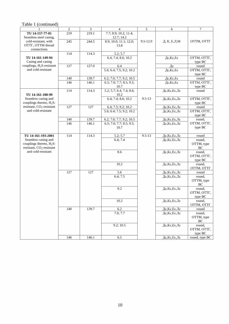
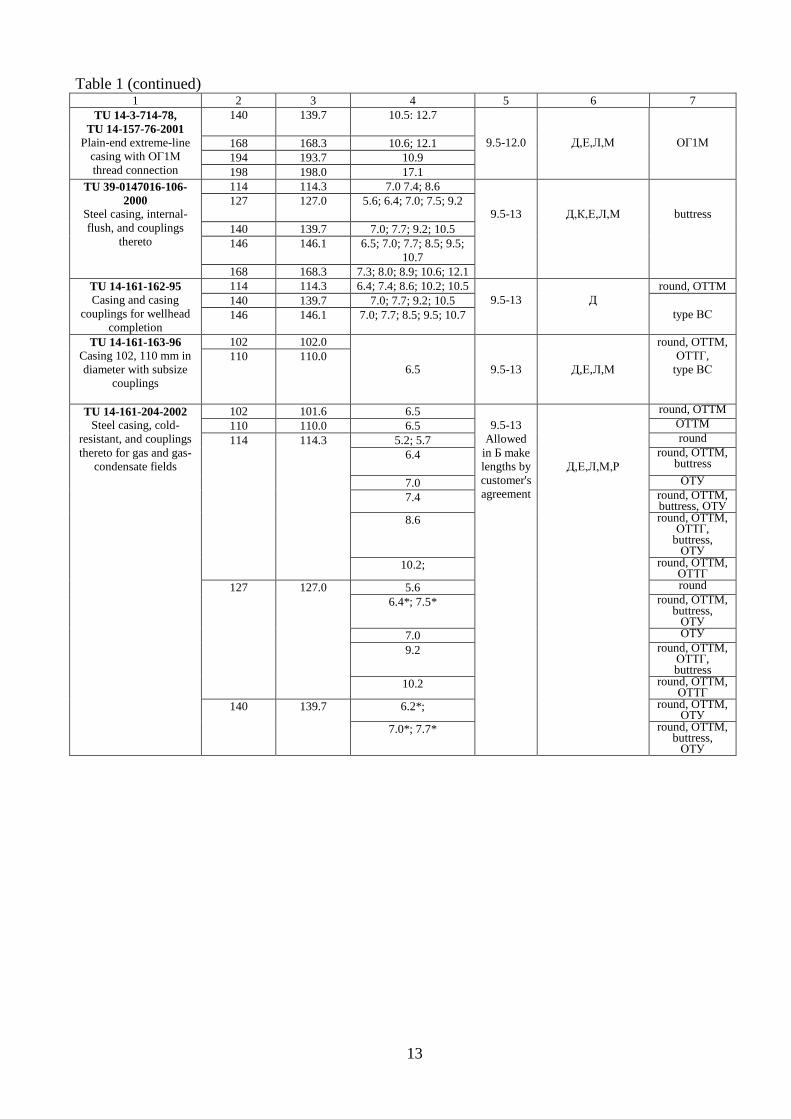
2.1 Range of casing manufactured by TMK pipe mills is given in Table 1.
Table 1 – Range of casing manufactured by TMK mills
Designation of
standard specification
Pipe dimensions Pipe grade Thread
connection Diameter, mm Wall thickness, mm Length,
m specified nominal
1 2 3 4 5 6 7
GOST 632-80
Casing and casing
couplings –
Specifications
114 114.3 5.2; 5.7
6.0-12.0
Д round
6.4 Д,К,Е,Л,М round,
OTTM 7.4* Д,К,Е,Л,М Р
8.6*; 10.2 Д,К,Е,Л,М Р round,
OTTM, ОТТГ
127 127.0 5.6
6.0-12.0
Д Round
6.4 Д,Е,Л,М round,
OTTM 7.5 Д,К,Е,Л,М,Р
9.2; 10.2 Д,К,Е,Л,М,Р round,
OTTM, ОТТГ
140 139.7 6.2
6.0-12.0
Д round,
OTTM 7.0 Д,К,Е,Л,М
7.7 Д,К,Е,Л,М,Р
9.2; 10.5 Д,К,Е,Л,М,Р round,
OTTM, ОТТГ
146 146.1 6.5
6.0-12.0
Д round,
OTTM
7.0; 7.7. 8.5;
Д,К,Е,Л,М round,
OTTM
9.5; 10.7 Д,К,Е,Л,М,Р
round,
OTTM, ОТТГ

6
Table 1 (continued) 1 2 3 4 5 6 7
GOST 632-80
Casing and casing
couplings –
Specifications
168 168.3 7.3
6.0-12.0
Д,К,Е,Л round,
OTTM 8.0; 8.9 Д,К,Е,Л,М
10.6; 12.1 Д,К,Е,Л,М round,
OTTM, ОТТГ
178 177.8 8.1; 13.7
6.0-12.0
Д,К,Е,Л,М
round,
OTTM
9.2; 10.4; 11.5; 12.7;
round,
OTTM, ОТТГ
194 193.7 7.6
6.0-12.0
Д,К,Е,Л,М
round,
OTTM 8.3
9.5; 10.9; 12.7; 15.1 round,
OTTM, ОТТГ
219 219.1 7.7
6.0-12.0
Д round,
OTTM
8.9; 10.2; 11.4;
12.7; 14.2
Д,К,Е,Л,М,Р round,
OTTM, ОТТГ
245 244.5 7.9
6.0-12.0
Д round,
OTTM
8.9; 10.0; 11.1;
12.0; 13.8; 15.9 Д,К,Е,Л,М,Р round,
OTTM, ОТТГ
273 273.1 8.9
6.0-12.0
Д,К,Е,Л,М round,
OTTM, ОТТГ 10.2; 11.4; 12.6; 13.8;
15.1; 16.5 Д,К,Е,Л,М,Р
324 323.9 8.5
6.0-12.0
Д round,
OTTM 9.5 Д,Е,Л
11.0;12.4;14.0 Д,К,Е,Л,М,Р
GOST R 53366-2009
(ISO 11960:2004)
Petroleum and natural
gas industries – Steel
pipe for use as casing or
tubing for wells –
General specifications
101 101.6 6.5
length
range
II. III
J55
L80; C95; P110 OTTM
114 114.3 5.21; 5.69 Н40; J55; K55; М65 round
6.35; 7.37;8.56 Н40; J55; K55;
М65; L80 type 1;
N80; C90; C95;
P110; Q125; Q135 round,
OTTM,ОТТГ,
ВС 10.2 Н40; J55; K55;
М65; L80 type 1;
N80; C90; Т95;
C95; P110
127 127.0
5.59 J55; K55; М65 round
6.43;
J55; K55; L80 type
1; N80; C90; Т95;
C95; P110
round,
OTTM,ОТТГ,
ВС
7.52 J55; K55; L80 type
1; N80; C90; Т95;
C95; P110: Q135
9.19; 11.10 J55; K55; L80 type
1; N80; C90; Т95;
C95; P110;
Q125;Q135
10.7; J55; K55; ; L80 type
1; N80; C95; P110;
Q125;Q135
12.14; 12.70 J55; K55; L80 type
1; N80; C90; C95;
P110; Q125
140 139.7 6.20 Н40; J55; K55;
М65; N80
round,
OTTM
6.98 Н40; J55; K55; L80
type 1; N80; C90;
Т95; C95; P110 round,
OTTM,ОТТГ,
ВС 7.72; 9.17; 10.54 Н40; J55; K55; L80
type 1; N80; C90;
Т95; C95; P110;
Q125;Q135

7
Table 1 (continued) 1 2 3 4 5 6 7
GOST R 53366-2009
(ISO 11960:2004)
Petroleum and natural
gas industries – Steel
pipe for use as casing or
tubing for wells –
General specifications
146 146.1 6.50 Н40; J55; K55;
М65; N80
round,
OTTM, ВС
7.00; 7.70 Н40; J55; K55; L80
type 1; N80; C90;
Т95; C95; P110
round
OTTM,
ВС
146 146.10 8.50; 9.50; 10.70
length
range
II, III
Н40; J55; K55; L80
type 1; N80; C90;
Т95; C95; P110;
Q125; Q135
round
OTTM,ОТТГ,
ВС
168 168.28 7.32 Н40; J55; K55;
М65; N80
round,
OTTM, ВС
8.00 Н40; J55; K55;
М65; L80 type 1;
N80; C95; P110
round
OTTM,ОТТГ,
ВС
8.94; 10.59; 12.06 Н40; J55; K55;
М65; L80 type 1;
N80; C90; Т95;
C95; P110;
Q125;Q135
round
OTTM,ОТТГ,
ВС
178 177.80 8.05 Н40; J55; K55;
М65; L80 type 1;
N80; C90; Т95; C95
round
OTTM,ОТТГ,
ВС
9.19; 10.36; 11.51;
12.65
Н40; J55; K55;
М65; L80 type 1;;
N80; C90; Т95;
C95; P110
round
OTTM,ОТТГ,
ВС
13.72 L80 type 1; N80;
C90; Т95; C95;
P110
round
OTTM,ОТТГ,
ВС
194 193.68 7.60 Н40; J55; K55 round
OTTM, ВС
8.33; 9.52; 10.92;
12.70
Н40; J55; K55; N80;
L80 type 1; C90;
Т95;; C95; P110;
Q125;Q135
round
OTTM,ОТТГ,
ВС
219 219.08 7.7 Н40; J55; K55;
М65; N80
round
OTTM, ВС
8.94; 10.16; 11.43;
12.70
Н40; J55; K55; N80;
L80 type 1; C90;
Т95; C95; P110;
Q125;Q135
round
OTTM,ОТТГ,
ВС
14.15 L80 type 1; N80;
C90; Т95 C95; C90;
Т95; P110;
Q125;Q135
round
OTTM,ОТТГ,
ВС
245 244.48 7.92 Н40; J55; K55; N80 round
OTTM, ВС
8.94; 10.03; 11.05;
11.99; 13.84
Н40; J55; K55;
М65; L80 type 1;
N80; C90; Т95;
C95;Р110;Q125;
Q135
round
OTTM,ОТТГ,
ВС
15.11 L80 type 1; N80;
C95; C90; Т95;
P110; Q125; Q135
round
OTTM,ОТТГ,
ВС
273
273.10 8.89; Н40; J55; K55;
М65; L80 type 1;
N80; C90; Т95;
C95; Р110
10.16; 11.43; 12.57;
13.84
J55; K55; М65; L80
type 1; N80; C95;
C90;
Т95;P110;Q125;
Q135
round
ВС
OTTM, ОТТГ

8
Table 1 (continued) 1 2 3 4 5 6 7
GOST R 53366-2009
(ISO 11960:2004)
Petroleum and natural
gas industries – Steel
pipe for use as casing or
tubing for wells –
General specifications
273
273.10 15.11
L80 Type 1; N80;
C95; С90; Т95;
P110; Q125;Q135
round
OTTM, ОТТГ,
ВС
16.50 J55; K55; L80 Type
1; C95; P110; Q135
round
OTTM, ОТТГ,
ВС
324 323.90 8.50 Н40; J55; K55;
М65; L80 Type 1;
C95; P110
round
OTTM, ВС
9.50; 11.10; 12.40;
14.0
Н40; J55; K55;
М65; L80 Type 1;
N80; C95; С90;
Т95;P110;Q125;
Q135
round
OTTM, ОТТГ,
ВС
340 339.70 8.38 Н40; J55; K55 round
9.65; 10.92 Н40; J55; K55;
М65; L80 Type 1;
N80; C95;C90; Т95;
round
OTTM, ВС
12.19; Н40; J55; K55;
М65; L80 Type 1;
N80; C95;C90; Т95;
Р110
13.06
Н40; J55; K55; L80
Type 1; N80; C95;
С90;
Т95;P110;Q125;
Q135
round
OTTM, ВС
API Spec 5CT /
ISO 11960:2004 Eighth edition
Specification for Casing
and Tubing /
Petroleum and natural
gas industries – Steel
pipe for use as casing or
tubing for wells
114 114.3 6.35; 7.37;8.56;
length
range
II, III
Н40; J55; K55;
М65; L80 Type 1;
N80; С90; Т95;
C95; P110; Q125
round,
ВС,
ТМК FМС
LС, STC,
ТМК GF
ТМК PF,
ТМК PF ET,
TMK CS,
TMK TTL -01,
ТМК 1
127 127.0 6.43; 7.52; 9.19; 10.16;
11.10; 12.14; 12.70
140 139.7 6.99; 7.72; 9.17; 10.54
168 168.28 7.32; 8.94; 10.59;
12.06
178 177.8 8.05; 9.19; 10.36;
11.51; 12.65; 13.72
194 193.68 8.33; 9.52; 10.92;
12.70
219 219.08 8.94; 10.16; 11.43;
12.70; 14.15
245 244.48 8.94; 10.03; 11.05;
11.99; 13.84; 15.11
273 273.1 8.89; 10.16; 11.43;
12.57; 13.84; 15.11
340 339.7 9.65; 10.92; 12.19;
13.06
TU 39.0147016-63-96
Casing and casing
couplings with buttress
thread
114 114.3 7.4; 8.6; 10.2
to GOST
632-80 Д, К, Е, Л type ВС
127 127 7.5; 9.2; 10.7
140 139.7 7.0; 7.7; 9.2; 10.5
146 146.1 7.0; 7.7; 8.5; 9.5; 10.7
168 168.3 7.3; 8.0; 8.9; 10.6; 12.1
178 177.8 8.1; 9.2; 10.4; 11.5;
12.7; 13.7
194 193.7 7.6; 8.3; 9.5; 10.9; 12.7
219 219.1 7.7; 8.9; 10.2; 11.4;
12.7; 14.2
245 244.5 7.9; 8.9; 10.0; 11.1;
12.0; 13.8

9
Table 1 (continued) 1 2 3 4 5 6 7
TU 14-162-13-95
Seamless casing with
buttress thread
connection and
couplings thereto
219 219.1 8.9; 10.2; 11.4; 12.7;
14.2
6.0-12.0
Д, Е, Л, М
type ВС 245 244.5 7.9; 8.9; 10.0; 11.1;
12.0; 13.8
273 273.1 8.9; 10.2; 11.4; 12.6;
13.8; 15.1
324 323.9 9.5; 11.0; 12.4; 14.0
TU 14-161-175-98
Steel casing and
couplings thereto
114
114.3
6.4
9.5-13.0
Д round thread
6.4 Д,Е,Л,М OTTM, ОТТГ,
type ВС 7.4; 8.6 Д,Е,Л,М,Р
10.2 Л,М,Р
127 127.0 5.6; 6.4; 7.5 Д round
6.4: 7.5; 9.2; 10.2 Д,Е,Л,М,Р OTTM, ОТТГ,
type ВС
140 139.7 6.2; 7.0; 7.7 Д round
6.2; 7.0; 7.7; 9.2; 10.5 Д,Е,Л,М,Р OTTM, ОТТГ,
type ВС
TU 14-161-175-98
Steel casing and
couplings thereto
146 146.1 6.5; 7.0; 7.7 9.5-13.0 Д round
6.5; 7.0 Д round,
OTTM, ОТТГ,
type ВС
7.7 Д round
7.7 Д,Е,Л,М OTTM, ОТТГ,
type ВС 8.5; 9.5; 10.7 Д,Е,Л,М,Р
168 168.3 7.3; 8.9 Д round
8 Д,Е
7.3; 8.0; 8.9; 10.6; 12.1 Д,К,Е,Л,М OTTM, ОТТГ,
type ВС
TU 14-157-24-92
Casing and casing
couplings, cold-resistant
114 114.3 8.6; 10.2
9.3-12.0
Д,Е,К,Л,М,Р
ОТТГ исп. А
ТМК FМС
127 127.0 9.2; 10.7
140 139.7 9.2; 10.5
146 146.1 8.5; 9.5; 10.7
168 168.3 8.9; 10.6; 12.1
178 177.8 9.2; 10.4; 11.5; 12.7
194 193.7 9.5; 10.9; 12.7
219 219.1 8.9; 10.2; 11.4; 12.7;
14.2
245 244.5 8.9; 10.0; 11.1; 12.0;
13.8
TU 14-ZR-76-2004
Casing and casing
couplings, cold-resistant
168 168.3 10.6; 12.1
6-11.7
Д,К,Е, Л,М
ОТТГ, OTTM
178 177.8 9.2; 10.4; 11.5; 12.7
219 219.1 8.9; 10.2; 11.4; 12.7
245 244.5 8.9; 10.0; 11.1; 12.0
324 323.9 9.5; 11.0; 12.4
TU 14-157-77-01
Seamless steel casing,
cold-resistant, with
ОТТГ, OTTM thread
connections
114 114.3 7.4; 8.6; 10.2
9.5-12.0
Д, К, Е,Л,М
OTTM, ОТТГ
127 127.0 7.5; 9.2; 10.7
140 139.7 7.0; 7.7; 9.2; 10.5
146 146.1 7.0; 7.7; 8.5; 9.5; 10.7
168 168.3 7.3; 8.0; 8.9; 10.6;
12.1
178 177.8 8.1; 9.2; 10.4; 11.5;
12.7; 13.7
194 193.7 7.6; 8.3; 9.5; 10.9; 12.7
10
Table 1 (continued) 1 2 3 4 5 6 7
TU 14-157-77-01
Seamless steel casing,
cold-resistant, with
ОТТГ, OTTM thread
connections
219 219.1 7.7; 8.9; 10.2; 11.4;
12.7; 14.2
9.5-12.0
Д, К, Е,Л,М
OTTM, ОТТГ 245 244.5 8.9; 10.0; 11.1; 12.0;
13.8
TU 14-161-149-94
Casing and casing
couplings, H2S-resistant
and cold-resistant
114 114.3 5.2; 5.7
6.4; 7.4; 8.6; 10.2 Дс,Кс,Ес OTTM, ОТТГ,
type ВС
127 127.0 6.4 Дс round
5.6; 6.4; 7.5; 9.2; 10.2 Дс,Кс,Ес OTTM, ОТТГ,
type ВС
140 139.7 6.2; 7.0; 7.7; 9.2; 10.5 Дс,Кс,Ес round
146 146.1 6.5; 7.0; 7.7; 8.5; 9.5;
10.7
Дс,Кс,Ес OTTM, ОТТГ,
type ВС
TU 14-161-180-99
Seamless casing and
couplings thereto, H2S-
resistant, CO2-resistant
and cold-resistant
114 114.3 5.2; 5.7; 6.4; 7.4; 8.6;
10.2
9.5-13
Дс,Кс,Ес,Лс round
6.4; 7.4; 8.6; 10.2 Дс,Кс,Ес,Лс OTTM, ОТТГ,
type ВС
127 127 6.4; 7.5; 9.2; 10.2 Дс,Кс,Ес,Лс round
5.6; 6.4; 7.5; 9.2; 10.2 Дс,Кс,Ес,Лс OTTM, ОТТГ,
type ВС
140 139.7 6.2; 7.0; 7.7; 9.2; 10.5 Дс,Кс,Ес,Лс round,
OTTM, ОТТГ,
type ВС 146 146.1 6.5; 7.0; 7.7; 8.5; 9.5;
10.7
Дс,Кс,Ес,Лс
TU 14-161-193-2001
Seamless casing and
couplings thereto, H2S-
resistant, CO2-resistant
and cold-resistant
114 114.3 5.2; 5.7 9.5-13 Дс,Кс,Ес,Лс round
6.4; 7.4 Дс,Кс,Ес,Лс round,
OTTM, type
ВС
8.6 Дс,Кс,Ес,Лс round,
OTTM, ОТТГ,
type ВС
10.2 Дс,Кс,Ес,Лс round,
OTTM, ОТТГ
127 127 5.6 Дс,Кс,Ес,Лс round
6.4; 7.5 Дс,Кс,Ес,Лс round,
OTTM, type
ВС
9.2 Дс,Кс,Ес,Лс round,
OTTM, ОТТГ,
type ВС
10.2 Дс,Кс,Ес,Лс round,
OTTM, ОТТГ
140 139.7 6.2 Дс,Кс,Ес,Лс round
7.0; 7.7 Дс,Кс,Ес,Лс round,
OTTM, type
ВС
9.2; 10.5 Дс,Кс,Ес,Лс round,
OTTM, ОТТГ,
type ВС
146 146.1 6.5 Дс,Кс,Ес,Лс round, type ВС

11
Table 1 (continued) 1 2 3 4 5 6 7
TU 14-161-193-2001
Seamless casing and
couplings thereto, H2S-
resistant, CO2-resistant
and cold-resistant
146 146.1 7.0; 7.7 9.5-13 Дс,Кс,Ес,Лс round,
OTTM, type
ВС
8.5; 9.5; 10.7 Дс,Кс,Ес,Лс round,
OTTM, ОТТГ,
type ВС
168 168.3 7.3; 8.0; 8.9; 10.6 Дс,Кс,Ес,Лс round,
OTTM, type
ВС
TU 14-157-47-97
Casing and casing
couplings with buttress
thread, corrosion-
resistant and cold-
resistant
114 114.3 8.56-10.2 range I
7.62-
10.36
J55, K55, N80, C95
type ВС
127 127 7.52-10.7
140 139.7 7.72-10.5
146 146.1 7.00; 7.70; 8.50; 9.50;
10.70
range II
10.36-
12.0 168 168.28 7.32; 8.94; 10.59;
12.07
178 177.88 8.05; 9.19; 10.36;
11.51; 12.65; 13.72
TU 14-157-47-97
Casing and casing
couplings with buttress
thread, corrosion-
resistant and cold-
resistant
194 193.68 8.33; 9.53; 10.92;
12.70; 14.27; 15.11;
15.88
range II
10.36-
12.0
J55, K55, N80, C95 type ВС
219 219.08 8.94; 10.16; 11.43;
12.70; 14.15
245 244.48 8.94; 10.03; 11.05;
11.99; 13.84; 15.11
TU 14-ZR-29-2007
Steel casing, seamless
and electric-welded, and
couplings thereto,
heavy-duty, with
buttress thread
connection
114 114.3 6.4; 7.4; 8.6; 10.2
9.5-13.0
Д,Е,Л,М;Р
type ВС
127 127 6.4; 7.5; 9.2; 10.7
140 139.7 6.2; 7.0; 7.7; 9.2; 10.5
146 146.1 6.5; 7.0; 7.7; 8.5; 9.5;
10.7
168 168.3 7.3; 8.0; 8.9; 10.6; 12.1
Дс1; Дс2
Д,Е,Л,М;Р
178 177.8 6.9; 8.1; 9.2; 10.4;
11.5; 12.7; 13.7; 15.0
194 193.7 7.6; 8.3; 9.5; 10.9;
12.7; 15.1
219 219.1 7.7; 8.9; 10.2; 11.4;
12.7; 14.2
245 244.5 7.9; 8.9; 10.0; 11.1;
12.0; 13.8; 15.9
273 273.1 8.89; 10.16; 11.43;
12.57; 13.84; 15.11
324 323.9 8.2; 9.5; 11.0; 12.4;
14.0
340 339.7 9.65; 10.92; 12.19;
13.06
TU 14-157-11-98
Steel casing with
packing assembly made
of polymeric material
140 139.7 7.0; 7.7
to GOST
632-80
6.0-12.0
Д,Е,Л,М
OTTM
9.2; 10.5 OTTM, ОТТГ
146 146.1 7.0; 7.7 OTTM
8.5; 9.5; 10.7 OTTM, ОТТГ
168 168.3 7.3; 8.0 OTTM
8.9; 10.6; 12.1 OTTM, ОТТГ
178 177.8 8.1; 13.7 OTTM
9.2; 10.4; 11.5; 12.7;
13.7
OTTM, ОТТГ
219 219.1 7.7; 8.9; OTTM
10.2; 11.4; 12.7; 14.2 OTTM, ОТТГ
245 244.5 7.9; OTTM
8.9; 10.0; 11.1;
12.0; 13.8
OTTM, ОТТГ

12
Table 1 (continued) 1 2 3 4 5 6 7
TU 14-162-102-2000
Longitudinal electric-
welded casing and
couplings thereto
219 219.1 7.7-10.2
9.0-12.0
Дс1, Дс2
OTTM,
type ВС 245 244.5 7.9-10.0
273 273.05 8.9-11.4 OTTM
324 323.9 8.9-11.0
TU 14-157-75-2001,
TU 14-157-83-2002,
TU 14-157-91-2003,
TU 14-157-92-2003
Casing with TMK-FMC
enhanced leak resistance
thread connection and
couplings thereto
114 114.3 8.6; 10.2
9.5-11.8
J55, K55, N80, L80,
C95, P110
Д,Е,Л,М
ТМК-FMC
127 127.0 9.2; 10.7
140 139.7 7.0; 7.7; 9.2; 10.5
146 146.1 7.0; 7.7; 8.5; 9.5; 10.7
168 168.3 8.9; 10.6; 12.1
TU 14-157-75-2001,
TU 14-157-83-2002,
TU 14-157-91-2003,
TU 14-157-92-2003
Casing with TMK-FMC
enhanced leak resistance
thread connection and
couplings thereto
178 177.8 9.2; 10.4; 11.5; 12.7;
13.7; 15.0
9.5-11.8
J55, K55, N80, L80,
C95, P110
Д,Е,Л,М
ТМК-FMC
194 193.7 9.5; 10.9; 12.7; 15.1
219 219.1 8.9; 10.2; 11.4; 12.7;
14.2
245 244.5 8.9; 10.0; 11.1; 12.0;
13.8; 15.9
TU 14-162-41-98
Seamless casing,
enhanced leak
resistance, size 324 mm,
with ОТТГ thread
connection, and
couplings thereto
324
323.9
9.5; 11.0; 12.4; 14.0
9.5-12.0
Д,Е,Л,М
ОТТГ
TU 14-162-53-2004
Casing ТТL-01 and
couplings thereto for
directional and
horizontal holes with
hole deviation rate up to
5°/10 m
219 10.2; 11.4; 12.7; 14.2
limited
8.0-12.0
Д.Е.Л.М.Р
ТТL-01
245 10.0; 11.1; 12.0; 13.8;
15.9
324 11.0; 12.4; 14.0
TU 1321-197-
00147016-01
Extreme-line steel
casing
114 114.3 6.4; 7.4
9.5-13
Д, К, Е, Л, М
Дхл, Кхл, Ехл,
Лхл, Мхл
according to
TU 120 120.0 6.9
127 127.0 6.4; 7.5
140 139.7 7.0; 7.7
TU 1321-205-
00147016-01
Casing and casing
couplings, CO2-resistant
and H2S-resistant
219-339
219.1-339.7
7.3-16.5
9.5-13
Е, Л
OTTM, ОТТГ,
type ВС
13
Table 1 (continued) 1 2 3 4 5 6 7
TU 14-3-714-78,
TU 14-157-76-2001 Plain-end extreme-line
casing with ОГ1М
thread connection
140 139.7 10.5: 12.7
9.5-12.0
Д,Е,Л,М
ОГ1М 168 168.3 10.6; 12.1
194 193.7 10.9
198 198.0 17.1
TU 39-0147016-106-
2000
Steel casing, internal-
flush, and couplings
thereto
114 114.3 7.0 7.4; 8.6
9.5-13
Д,К,Е,Л,М
buttress 127 127.0 5.6; 6.4; 7.0; 7.5; 9.2
140 139.7 7.0; 7.7; 9.2; 10.5
146 146.1 6.5; 7.0; 7.7; 8.5; 9.5;
10.7
168 168.3 7.3; 8.0; 8.9; 10.6; 12.1
TU 14-161-162-95
Casing and casing
couplings for wellhead
completion
114 114.3 6.4; 7.4; 8.6; 10.2; 10.5
9.5-13
Д
round, OTTM
140 139.7 7.0; 7.7; 9.2; 10.5
type ВС 146 146.1 7.0; 7.7; 8.5; 9.5; 10.7
TU 14-161-163-96
Casing 102, 110 mm in
diameter with subsize
couplings
102 102.0
6.5
9.5-13
Д,Е,Л,М
round, OTTM,
ОТТГ,
type ВС 110 110.0
TU 14-161-204-2002
Steel casing, cold-
resistant, and couplings
thereto for gas and gas-
condensate fields
102 101.6 6.5
9.5-13
Allowed
in Б make
lengths by
customer's
agreement
Д,Е,Л,М,Р
round, OTTM
110 110.0 6.5 OTTM
114 114.3 5.2; 5.7 round
6.4
round, OTTM, buttress
7.0 ОТУ
7.4 round, OTTM, buttress, ОТУ
8.6 round, OTTM, ОТТГ,
buttress, ОТУ
10.2; round, OTTM, ОТТГ
127 127.0 5.6 round
6.4*; 7.5* round, OTTM, buttress,
ОТУ
7.0 ОТУ
9.2 round, OTTM, ОТТГ, buttress
10.2 round, OTTM, ОТТГ
140 139.7 6.2*; round, OTTM, ОТУ
7.0*; 7.7* round, OTTM, buttress,
ОТУ

14
Table 1 (continued) 1 2 3 4 5 6 7
TU 14-161-204-2002
Steel casing, cold-
resistant, and couplings
thereto for gas and gas-
condensate fields
140 139.7 9.2*; round, OTTM, ОТТГ, buttress
ОТУ
10.5 round, OTTM, ОТТГ, buttress
146 146.1 6.5*; 7.0*; 7.7*;
round, OTTM, buttress,
ОТУ
8.5*; 9.5*; 10.7 round, OTTM, ОТТГ,
buttress, ОТУ
168 168.3 7.3*; 8.0*;
round, OTTM, buttress,
ОТУ
8.9*;10.6*; 12.1* round, OTTM, ОТТГ,
buttress, ОТУ
TU 1321-261-
00147016-03
Steel casing, internal-
flush, 102, 110 mm in
diameter, shouldered
within small-size
couplings
102 101.6
7.0
to GOST
632-80
Д, К, Е, Л, М
OTTM 110 110.0
TU 14-3-514-76
Casing and casing
couplings
140 139.7 7.0; 7.7; 9.2; 10.5
9.5-13
Д
round 146 146.1 6.5; 7.0; 7.7; 8.5; 9.5;
10.7
TU 14-ZR-82-2005
Casing and casing
couplings, cold-resistant
for OAO GAZPROM
140 139.7 7.72 - 10.54
6.0-12.0
Д,К,Е,Л,М,Р
J55,K55,N80, L80,
С95, P110
ТМК GF 168 168.3 8.9 - 12.1
178 177.8 8.1 - 15.0
219 219.1 8.9-14.2 OTTM, ОТТГ,
buttress,
ТМК ТТL-01,
ТМК FMC,
ТМК GF
244 244.5 8.9-15.9
273 273 8.9-16.5
324 323.9 9.5-14.0
TU 14-157-93-2007
Steel seamless casing,
H2S-resistant, and
couplings thereto, with
ТМК-FМС enhanced
leak resistance thread
connection
114 114.3 8.6; 10.2
9.5-11.8
L80C
ТМК-FMC
127 127.0 9.2; 10.7
140 139.7 7.0; 7.7; 9.2; 10.5
146 146.1 7.0; 7.7; 8.5; 9.5; 10.7
168 168.3 8.9; 10.6; 12.1
178 177.8 9.2; 10.4; 11.5; 12.7;
13.7; 15.0
194 193.7 9.5; 10.9; 12.7; 15.1
219 219.1 8.9; 10.2; 11.4; 12.7;
14.2
TU 14-157-97-2007
Steel seamless casing
and cold-resistant
couplings thereto with
ТМК GF enhanced leak
resistance thread
connection
140 139.7 7.72; 9.17; 10.54
9.5-11.8
L80, J55, K55,
N80Q, C95, P110
ТМК GF 168 168.28 7.32; 8.94; 10.59;12.06
178 177.8 8.05; 9.19; 10.36
11.51; 12.65

15
Table 1 (continued) 1 2 3 4 5 6 7
TU 14-157-99-2005
Seamless extreme-line
steel casing with TMK1
thread connection
102 101.60 5.74; 6.65
10.0-11.3
Д, Е, Л, М,
J55, K55, N80,
N80Q, L80 Type 1,
C95, P110, Q 125
Type 1
ТМК1 114 114.3 6.88; 8.56
120 120 6.90; 8.00
140 139.7 7.00; 7.70
Note – * at the initial production stage
2.2 Mechanical properties of casing manufactured in accordance with GOST 632 are given in Table 2.
Table 2 – Mechanical properties of casing made to GOST 632
Pipe grade Yield strength, σY Tensile strength, σT Elongation
δ5, %, min min max
Д 379 552 655 14.3
К 490 – 687 12.0
Е 552 758 689 13.0
Л 655 862 758 12.3
М 758 965 862 10.8
Р 930 1137 1000 9.5
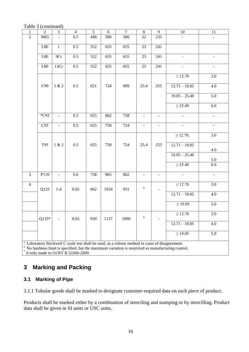
2.3 Mechanical properties of casing manufactured in accordance with GOST R 53366-2009 and API Spec
5CT are given in Table 3.
Table 3 – Mechanical properties of casing made to GOST R 53366-2009 and API Spec 5CT
Group
Pipe
grade
Type
Total
elongation
under
load, %
Yield strength
Rt, MPa
Tensile
strength
Rm, MPa,
min
Hardness, maxа
Specified wall
thickness
t, mm
Permissible
hardness b
variation, HRC min max HRC HBW
1 2 3 4 5 6 7 8 9 10 11
1 Н40 - 0.5 276 552 414 - - - -
Ј55 - 0.5 379 552 517 - - - -
K55 - 0.5 379 552 655 - - - -
K72* - 0.5 491 - 687 - - - -
N80 1 0.5 552 758 689 -
N80
Q 0.5 552 758 689 - - - -
16
Table 3 (continued) 1 2 3 4 5 6 7 8 9 10 11
2
M65 - 0.5 448 586 586 22 235 - -
L80 1 0.5 552 655 655 23 241
L80 9Cr 0.5 552 655 655 23 241 - -
L80 13Cr 0.5 552 655 655 23 241 - -
С90
1 & 2
0.5
621
724
689
25.4
255
≤ 12.70 3.0
12.71 – 19.05
4.0
19.05 – 25.40
5.0
≥ 25.40
6.0
*С95 - 0.5 655 862 758 - - - -
С95 - 0.5 655 758 724 - - - -
Т95
1 & 2
0.5
655
758
724
25.4
255
≤ 12.70. 3.0
12.71 – 19.05
4.0
19.05 – 25.40
5.0
≥ 25.40
6.0
3 Р110 - 0.6 758 965 862 - - - -
4
Q125
1-4
0.65
862
1034
931
b
-
≤ 12.70 3.0
12.71 – 19.05
4.0
≥ 19.05
5.0
Q135*
-
0.65
930
1137
1000
b
-
≤ 12.70 3.0
12.71 – 19.05
4.0
≥ 19.05
5.0
a Laboratory Rockwell C scale test shall be used. as a referee method in cases of disagreement. b No hardness limit is specified, but the maximum variation is restricted as manufacturing control. * if only made to GOST R 53366-2009
3 Marking and Packing
3.1 Marking of Pipe
3.1.1 Tubular goods shall be marked to designate customer-required data on each piece of product.
Products shall be marked either by a combination of stenciling and stamping or by stencilling. Product
data shall be given in SI units or USC units.

17
Marking information applied by stamping or hot rolling and stenciling shall be in accordance with the
requirements of product standards/specifications.
Corrosion-resistant pipe shall be only marked by stenciling; no stamping shall be applied.
Examples of pipe and coupling marking in accordance with GOST 632 and API Spec 5CT are given in
Figs 1 – 4.
Fig. 1 shows an example of marking casing and couplings to GOST 632.
Figs 2, 3, 4 show examples of marking casing and couplings to API Spec 5CT.
Pipe made to TU specifications shall be marked in accordance with applicable TU requirements.

18
77
75
9
146 Е
7.7
06 07
146 (Е) 7.7 1083 304 OTTM А
50
ТЗ
Д
С
А
coupling
1 5-8 1 pipe 30-35
Rolled
marking Stenciling zone
400-600 zone 15-30
Stamped or rolled marking information Stenciling information
77759 - pipe No 146 - pipe specified diameter, mm
146 - pipe specified diameter, mm ( ) - ultrasonic examination
Е - pipe grade Е - pipe grade
7.7 - wall thickness, mm 7.7 - wall thickness, mm
- manufacturer's trade mark 1083 - pipe length, cm
06 - month of manufacture 304 - pipe weight, kg (marked at weight check)
07 - year of manufacture OTTM - connection type (not marked for pipe with short round thread)
Note: 1 – location of rolled marking shall be encircled by light-color paint А - Make (marked when Make A pipe are delivered)
- manufacturer's trade mark
Marking of couplings by stamping Designation Information
ТЗ coupling manufacturer's trade mark
Д grade
С special couplings for OTTM and ОТТГ pipe
А Make (only for Make А)
Note: marking characters may be applied on the coupling faces
Fig. 1 – Marking example for casing 146 7.7 mm, pipe grade "Е" with OTTM thread connection to GOST 632
19
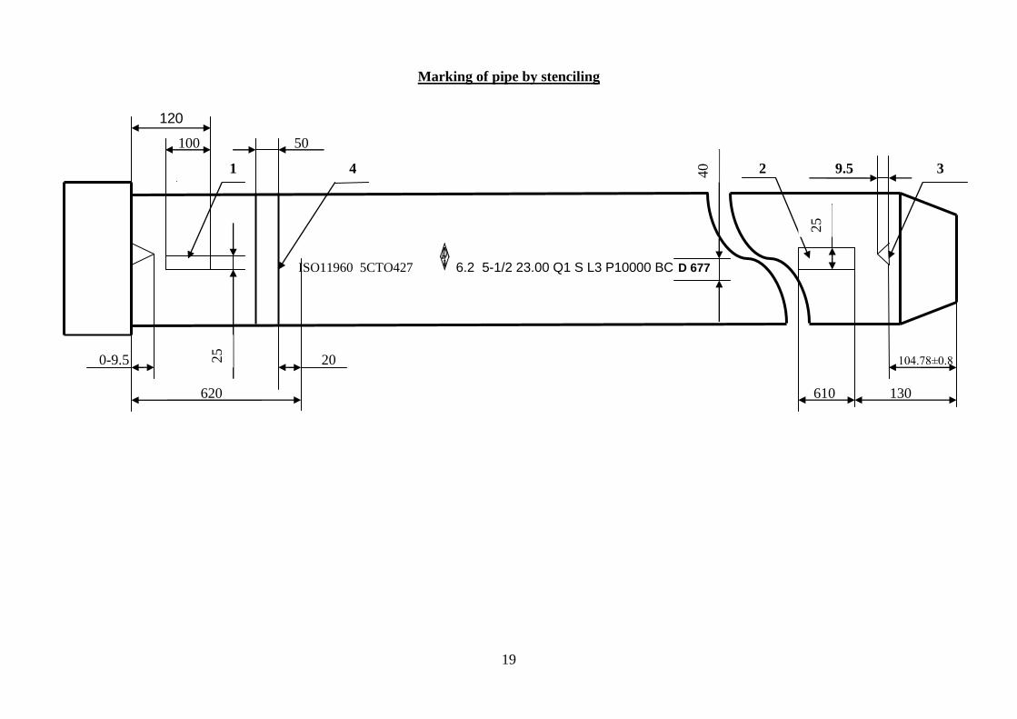
ISO11960 5CTO427 6.2 5-1/2 23.00 Q1 S L3 P10000 BC D 677
40
25
25
Marking of pipe by stenciling
120
100 50
1 4 2 9.5 3
0-9.5 20 104.78±0.8
620 610 130

20
Pipe stenciling information
ISO11960 - International standard ISO 11960
5СТ0427 - License No
- API Monogram
6 - year of manufacture (the last digit)
2 - quarter of manufacture
5-1/2 - size designation, Label 1 (diameter, inches)
23.00 - weight designation, Label 2 (lb/ft)
Q1 - steel grade Q125, type 1
S - process of manufacture (seamless pipe)
L3 - product specification level PSL3
P10000 - hydrostatic test pressure (psi)
BC - buttress thread
D - standard drift mandrel
677 - unique No of length of pipe
Notes:
1. Paint a band 100 25 mm on the pipe mill end against the make-up triangle.
2. Paint a band 610 25 mm on the pipe field end against the make-up triangle.
3. Make-up triangle.
4. Orange band: color coding for grade Q125, Type 1.
Fig. 2 – Marking example for pipe with coupling 139.7 10.54 mm, grade Q125, Type 1, with buttress thread connection to API Spec 5CT, PSL-3

21
ISO11960 5CTO427 6.2 5-1/2 23.00 Р S L3 P9900 BC D
40
25
25
5СТО427
6.2
23.00 P S
45
71
2
Marking by stamping Marking by stenciling
120
100 50 4
1 2 9.5 3
0-9.5 20 104.78±0.8
320 610 130
620

22
Information of marking by stamping Information of marking by stenciling
45712 - No of pipe length ISO11960 - International standard ISO 11960
5СТ0427 - License No 5СТ0427 - License No
- API Monogram
- API Monogram
6 - year of manufacture (the last digit) 6 - year of manufacture (the last digit)
2 - quarter of manufacture 2 - quarter of manufacture
23.00 - weight designation, Label 2 (lb/ft) 5-1/2 - size designation, Label 1 (diameter, inches)
Р - steel grade Р110 23.00 - weight designation, Label 2 (lb/ft)
S - process of manufacture (seamless pipe) Р - steel grade Р110
S - process of manufacture (seamless pipe)
L3 - product specification level PSL3
P9900 - hydrostatic test pressure (psi)
BC - buttress thread
D - standard drift mandrel
Notes:
1. Paint a band 100 25 mm on the pipe mill end against the make-up triangle.
2. Paint a band 610 25 mm on the pipe field end against the make-up triangle.
3. Make-up triangle.
4. White band: color coding for grade P110.
Fig. 3 – Marking example for pipe with coupling 139.7 10.54 mm, grade P110, Type 1, with buttress thread connection to API Spec 5CT, PSL-3
23
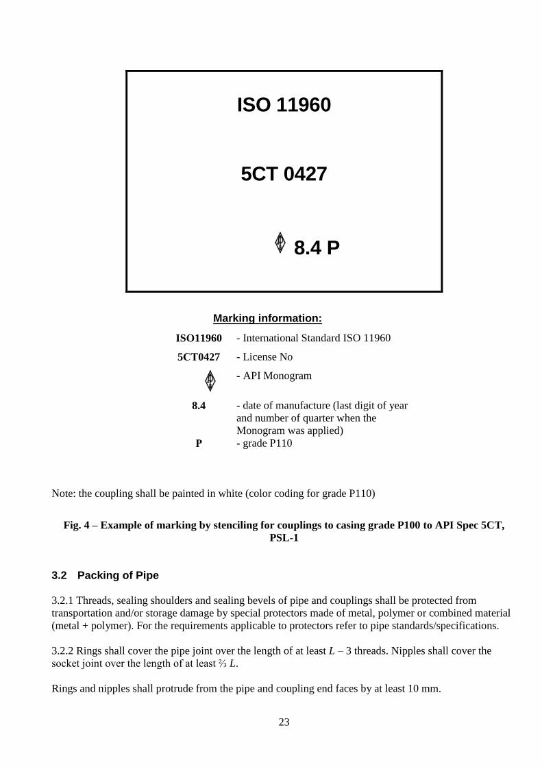
ISO 11960
5CT 0427
8.4 P
Marking information:
Note: the coupling shall be painted in white (color coding for grade P110)
Fig. 4 – Example of marking by stenciling for couplings to casing grade P100 to API Spec 5CT,
PSL-1
3.2 Packing of Pipe
3.2.1 Threads, sealing shoulders and sealing bevels of pipe and couplings shall be protected from
transportation and/or storage damage by special protectors made of metal, polymer or combined material
(metal + polymer). For the requirements applicable to protectors refer to pipe standards/specifications.
3.2.2 Rings shall cover the pipe joint over the length of at least L – 3 threads. Nipples shall cover the
socket joint over the length of at least ⅔ L.
Rings and nipples shall protrude from the pipe and coupling end faces by at least 10 mm.
ISO11960 - International Standard ISO 11960
5СТ0427 - License No
- API Monogram
8.4 - date of manufacture (last digit of year
and number of quarter when the
Monogram was applied)
Р - grade Р110

24
3.2.3 The design and material of protectors shall ensure unscrewing thereof, prevent the dust and moisture
from ingress in the thread during transportation and handling. The material shall be free from components
contributing to corrosion or to the engagement of protectors with a thread.
3.2.4 When screwing-on protective elements, thread connection shoulders and sealing bevels shall be
coated with rust-preventive compound. At customer's request, when specified in the purchase order,
thread-sealing compound may be used instead of rust-preventive compound.
For the requirements applicable to protectors during packing refer to 3.2.1.
3.2.5 Only pipe of the same pipe lot shall be shipped in a single carload.
Pipe of different pipe lots may be shipped in a single carload, provided the pipe of different lots are
segregated, if a pipe lot or a remainder thereof is not consistent with the car capacity.
3.2.5 Pipe shall be delivered in bundles, securely bundled in at least two points.
3.2.6 One bundle shall only contain pipe of the same pipe lot.
3.2.7 Bundling material shall not be used as slinging fixture. The packing shall allow for multiple
transfers of bundles with pipe undamaged.
3.2.8 The following pipe packing patterns are used in TMK Company: "extra", "economic", "ordinary"
and "simplified". The required pipe packing pattern shall be specified in the purchase order.
3.2.8.1 The above named four packing patterns provide for uniform weight of bundles for all patterns and,
accordingly, the same quantity of similar in diameter and wall thickness lengths of pipe per bundle.
To fill the purchase order according to the volume (tonnage, footage) specified by the customer, one to
two bundles of the ordered pipe lot, which contain less weight or less lengths of pipe than specified by
packing patterns, may be formed.
3.2.8.2 For the "extra" packing pattern, casing shall be bundled so that any contact between pipe bodies,
couplings, tool joint elements, upsets be positively precluded. This is achieved by laying pipe on supports.
At customer's request, supports are made as external or internal, wooden or metal/polymeric. A support
provides a cradle for each length of pipe. Supports filled with pipe shall be bundled with steel band or by
stud bracing.
For the requirements applicable to protectors refer to 3.2.1.
Each bundle shall have three tags secured thereto: one tag at the aligned end of the bundle, and another
two tags, at the sides of the bundle.
The tag shall contain the following information:
Trade mark and manufacturer
Consignee
Station of destination
Purchase Order No
Bundle No
Lot No
Heat No

25
GOST, TU No
Size
Steel grade (pipe grade)
Number of lengths
Length, m
Weight, metric tons
Address and contact phone
3.2.8.3 For the "economic" packing pattern, casing shall be bundled on external or internal wooden
supports.
Threads and pipe ends shall be protected in accordance with 3.2.1.
Each bundle shall have two tags secured thereto: one tag at the aligned end of the bundle, and another tag
at the left (of the aligned end) side of the bundle.
3.2.8.4 For the "ordinary" packing pattern, tubing shall be bundled on external or internal wooden
supports.
Threads and pipe ends shall be protected in accordance with 3.2.1.
3.2.8.5 For the "simplified" packing pattern, casing shall be packaged in accordance with GOST 10692
requirements and shipped according to the loading patterns accepted at the manufacturer's facility.
The protection of pipe ends and threaded elements shall be in accordance with the requirements of
standards/specifications applicable to the manufacture of pipe under shipment.
The protectors shall be fitted on pipe ends, taking into account the geographical area of the destination,
e.g., protectors made of cold-resistant plastic where pipe are delivered to areas with low average yearly
temperature.
3.2.9 For all types of packing, when forming a bundle of casing, the couplings shall face the same
direction.
3.2.10 For the "extra", "economic" and "ordinary" packing patterns, all pipe ends facing one direction
shall be coplanar. Misalignment of the opposite pipe ends in the bundle shall not exceed 0.5 m.
3.2.11 Casing shall be packed in bundles using external or internal supports and loaded in a car in
accordance with Table 4.
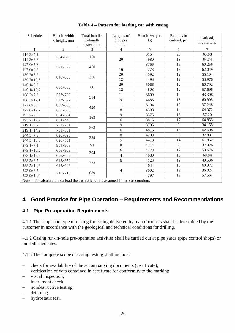
26
Table 4 – Pattern for loading car with casing
Schedule Bundle width
height, mm
Total bundle-
to-bundle
space, mm
Lengths of
pipe per
bundle
Bundle weight,
kg
Bundles in
carload, pc. Carload,
metric tons
1 2 3 4 5 6 7
114,35,2 534668 150
20
3154 20 63.08
114,38,6 4980 13 64.74
127,05,6 592592 450
3766 16 60.256
127,09,2 16 4773 13 62.049
139,76,2 640800 256
20 4592 12 55.104
139,710,5 12 4498 12 53.976
146,16,5 690863 60
20 5066 12 60.792
146,110,7 12 4808 12 57.696
168,37,3 577769 514
11 3609 12 43.308
168,312,1 577577 9 4685 13 60.905
177,85,9 600800 420
11 3104 12 37.248
177,812,7 600600 8 4598 14 64.372
193,77,6 664664 163
9 3575 16 57.20
193,712,7 664443 6 3815 17 64.855
219,16,7 751751 563
9 3795 9 34.155
219,114,2 751501 6 4816 13 62.608
244,57,9 826826 339
8 4209 9 37.881
244,513,8 826551 5 4418 14 61.852
273,17,1 909909 91 8 4214 9 37.926
273,110,2 606909 394
6 4473 12 53.676
273,116,5 606606 4 4680 13 60.84
298,58,5 648972 223
6 4128 12 49.536
298,514,8 648648
4
4644 13 60.372
323,98,5 710710 689
3002 12 36.024
323,914,0 4797 12 57.564
Note – To calculate the carload the casing length is assumed 11 m plus coupling.
4 Good Practice for Pipe Operation – Requirements and Recommendations
4.1 Pipe Pre-operation Requirements
4.1.1 The scope and type of testing for casing delivered by manufacturers shall be determined by the
customer in accordance with the geological and technical conditions for drilling.
4.1.2 Casing run-in-hole pre-operation activities shall be carried out at pipe yards (pipe control shops) or
on dedicated sites.
4.1.3 The complete scope of casing testing shall include:
– check for availability of the accompanying documents (certificate);
– verification of data contained in certificate for conformity to the marking;
– visual inspection;
– instrument check;
– nondestructive testing;
– drift test;
– hydrostatic test.
27
4.1.4 In the absence of a certificate of conformity to the requirements of product standards/specifications,
the acceptance, pre-operation and use of casing for string assembly is prohibited.
4.1.5 Instrumentation used for pipe quality control shall be certified and verified in accordance with
specified procedures.
4.1.6 Each length of casing should be drift-tested along the entire length immediately prior to running.
The testing shall be made using drift mandrels conforming to the requirements of GOST 632, GOST R
53366, TU specifications for pipe made to the said GOSTs, and to the requirements of ISO 11960 and
API Spec 5CT. During testing make sure that threads, packing and shoulder surfaces of couplings and
pipe are properly protected from any damage. Casing that failed to pass the drift test shall be put aside.
4.1.7 For pipe that were repaired at central pipe yards, the yard shall issue an individual certificate
indicating the field of application and hole lining limitations.
4.1.8 All casing, both new and reconditioned, shall be always handled with thread protectors in place.
Casing shall be placed on supports or on wooden/metal pads freed from stones, sand or mud, other than
drill mud.
4.1.9 The customer is free to decrease the number of controlled variables, taking into account the
established inspection at manufacturers' facilities and the guarantees of pipe conformity to the
requirements of standards and specifications (TU).
However, during transportation and delivery of pipe to the customer, some variables may be brought out
of tolerance; therefore, the following shall be retained as required testing:
– visual inspection;
– hydrostatic test;
– drift test;
– failing protectors (lost in transit), gauging.
If, during the hydrostatic test, a pipe thread connection proves leaky, the coupling torquing is allowed.
The pipe that has endured the hydrostatic retest shall be considered fit for service.
4.1.10 Immediately prior to running casing remove the protectors from the pipe field end and mill end,
thoroughly clean and examine the thread. If even minor thread damages beyond repair are detected, the
affected length of pipe shall be put aside.
4.1.11 Rejected pipe shall be stored on the rejected pipe rest racks.
Prior to running in hole, the length of each casing length shall be measured with a steel measuring tape
calibrated in millimeters with the least graduation of 3.0 mm.
The length shall be measured from the unengaged coupling face to the power-tight position of coupling
face along the pin end of pipe. For round thread connections, OTTM and ОТТГ connections, such a
position shall be the last hairline of the thread; for buttress connection the said position shall be the base
of the make-up triangle.
28
4.2 Casing String Forming
4.2.1 The selection of casing and casing string mechanical design shall be made taking into account the
maximum anticipated external and internal pressure on complete displacement of drill mud with
formation fluid or liquid-gas mixture, recession of fluid level in the course of well development or
artificial lifting, the loads occurring as a result of 3D deflection profile, as well as axial loads applied to
the pipe and corrosive properties of fluid at the construction and operation phases.
4.2.2 For the casing string design, standards/specifications approved by Rostekhnadzor shall be used.
4.2.3 A string running procedure shall be developed; such procedure shall provide for properly
proportioned stressing of pipe upon cement setting. This is necessary to avoid the occurrence of critical
stresses or excessive and/or dangerous tensile stresses during the well operation.
4.2.4 Casing exposed to hydrogen sulfide shall be selected in accordance with the manufacturing process
variables and corrosion environment properties.
4.2.5 The conformity of casing to applicable specifications and SSC (sulfide stress cracking) resistance of
pipe shall be confirmed by a certificate.
4.2.6 For the mechanical design of casing operating in H2S-bearing environment, a pressure containment
derating factor (KS) [38] shall be introduced to address this condition.
4.2.7 Thread connections shall be selected in accordance with [39] and Table 5.
4.2.8 Casing string sections shall be formed of commissioned pipe in accordance with the string design.
4.2.9 The pipe length sequence number shall be applied with permanent light paint on the outside
diameter close to the field end.
4.2.10 The numbering sequence shall be in accordance with the sequence of running pipe in the hole.

29
Table 5 – Recommended application of thread connections for casing strings
Gauge pressure, MPa Thread connection design Note
Liquid environment, γ ≥ 0,3104 N/m
3
≤45
OTTM
buttress
Use of round short thread (STC) and
long thread (LC) is allowed
ОТТГ
ТМК-TTL-01
TMK CS
TMK FMC
TMK GF
TMK PF
Applicable for H2S-bearing
environment
>45
OTTM and buttress with PTFE
ring
ОТТГ
ТМК-TTL-01
TMK CS
TMK FMC
TMK GF
TMK PF
Applicable for H2S-bearing
environment
Gaseous environment, γ ≤ 0,3104 N/m
3
≤45 ОТТГ
>45
ТМК-TTL-01
TMK CS
TMK FMC
TMK GF
TMK PF
Applicable for H2S-bearing
environment
Notes:
1) For pipe ≤ 168 mm in diameter at hole deviation rate up to 5°/10 m and for pipe > 168 mm in
diameter at hole deviation rate up to 3°/10 m, the mechanical design shall be made as for pipe in
vertical hole, without regard to any deflection.
2) For pipe > 168 mm in diameter at hole deviation rate 3° to 5°/10 m, the permissible tensile load shall
be reduced by 10%, with the exception of TMK GF and TMK PF thread connections.
3) At hole deviation rate of 5°/10 m, use of TMK GF and TMK PF thread connections is recommended.
4.3 Running Casing
4.3.1 Personnel involved in the assembly of casing strings shall be trained and qualified for the operations
in question.
4.3.2 When running a combined casing string make sure that the racks accommodating the casing
intended for use according to the assembly program are freely accessible.
4.3.3 Make sure that each length of casing be run in strict compliance with the sequence defined at the
design phase. Should any length of pipe appear unidentifiable, put it aside until the pipe weight and
connection type and size are ascertained.
4.3.4 Prior to makeup of subs and connectors make sure that the mating threaded parts are of the same
type and size.
30
4.3.5 Pipe shall be unloaded with mill ends facing the wellhead. Pipe shall be stacked on racks in
accordance with the running sequence. Standby lengths of pipe shall be stacked separately, so as to
provide free access thereto.
4.3.6 Place thread protectors on the field end of the pipe so that the thread will not be damaged while
rolling pipe on the rack and pulling into the derrick. Several thread protectors may be cleaned and used
repeatedly for this operation. Exercise due care when laying pipe on and rolling pipe to the walkway; use
a cable damper, if required. Transfer of pipe to the walkway shall be made impact-free, preventing the
pipe from hitting against any part of the derrick or other equipment. When pulling pipe into the derrick,
prevent the pipe from any deflection. Exercise special care when operating high-grade casing (grade E
and higher) and casing having thread connections packing with PTFE rings and metal-to-metal packing.
4.3.7 If a combined string or a string containing unmarked lengths of pipe is to be run, drift each length of
pipe with a mandrel to avoid running pipe having excessive weight or insufficient inside diameter.
4.3.8 Exercise due care when pulling casing strings into the derrick and lowering; when bracing the slips
observe safety precautions to avoid the application of impact loads. Should the string drop down, even a
short distance, the lower-end coupling may break out. Make proper arrangements to avoid the setting-
down of casing at the lower end or the compression of casing due to other causes, as these may cause pipe
to buckle, particularly within the part of the well where the hole enlargement has occurred.
4.3.9 After pulling pipe into the derrick and immediately before stabbing, screw protectors off the field
end; thereafter, the protectors shall be submitted to UPTO and KO, CBPO or CTB for further delivery to
manufacturers.
4.3.10 If the protective ring is dirty, check the condition of field end thread. If the thread is dirty or
corroded it shall be reconditioned followed by the application of thread-sealing compound.
4.3.11 The selection of thread connections and thread-sealing compound by leak resistance criteria should
be made in accordance with Table 6, while the application of compound should be made in accordance
with 4.5.5.
4.3.12 Pipe shall be stabbed in the upright position using, whenever possible, a centralizer. A pin should
be stabbed with due care, avoiding any hitting of threaded ends.
4.3.13 Make sure that immediately prior to stabbing the pin no dirt finds its way to the thread, and no
thread skew occurs due to pin-to-box misalignment.
4.3.14 To prevent the thread from skew, pipe should be centralized from a dedicated site located at the
level of upper pipe end, or from the derrickman's movable platform.
4.3.15 If, after stabbing, the length of pipe is skewed, slightly lift it, pull aside, clean the thread surface
from thread compound (sealing compound) or packing material and grind minor imperfections of thread
with a smooth-cut file. After the thread is thoroughly cleaned apply thread compound (sealing compound)
or packing material. After stabbing rotate the pipe, at first very slowly, to make sure that threads are
properly engaged without cross-threading. Casing with threads showing clearly pronounced evidence of
damage (distortion) shall be rejected.
4.3.16 A thread connection should be made up at first hand-tight (turned home), then with circular tongs.
Rotate the pipe slowly (10 rpm, max) to make sure that threads are properly engaged without cross-
threading.
31
4.3.17 If casing has a tendency to wobble unduly at its upper end when making up, indicating that the
thread may not be in line with the axis of the casing, the speed of rotation should be decreased to prevent
galling of threads.
If wobbling should persist despite reduced rotational speed, the casing should be
laid down for inspection. Do not use such casing in a string to be exposed to heavy tensile loads.
4.3.18 After pre-makeup, the thread connections shall be torqued with pipe spanners AKO or AKB (for
pipe up to 299 mm in diameter) or with power tongs equipped with a torque gauge. To prevent pipe from
crushing make sure that tong dies protrude from the slots by the die cutting height (2 to 3 mm),
maximum.
During makeup of casing at the drill site the coupling may slightly rotate in the mill-made connection.
This does not indicate insufficient mill screwing of the coupling, but rather confirms that torquing effort
reaches the same value as during makeup of the connection at the mill.
4.3.19 Recommended torque values are given in Annex A.3 and Annex A.7 for API Spec 5B thread
connections in accordance with ISO 10405 recommendations. Estimated torque values for GOST 632
thread connections are given for nominal standoff at friction coefficient of 0.06.
These values shall be only considered a guide, due to the very wide variations in torque requirements that
can exist for a specific connection. Because of this, it is essential that these torque values be related to the
average obtained in the course of pipe assembly by linear dimensions.
The torque values listed in Table 1 apply to casing with zinc-plated or phosphate-coated couplings. The
listed torque values are not applicable for making up couplings with PTFE rings. When making
up round thread connections with PTFE rings, 70 percent of the listed values are recommended. Buttress
connections with PTFE seal rings may make up at torque values different from those normally observed
on OTTM, ОТТГ and buttress threads.
4.3.20 To adjust the thread connection makeup torque, it is advisable when starting to run casing from
each particular mill shipment to make up sufficient joints to determine the torque necessary to provide
optimum makeup, with the power makeup turns (following the hand-tight makeup) recorded.
For power makeup of round thread connections, make approximately three more turns beyond the hand-
tight position for pipe 114.3 – 178.8 mm in diameter, and approximately three and a half more turns
beyond the hand-tight position for pipe ≥ 193.7 mm in diameter, with the exception of 244.5 mm and
273.1 mm diameters for pipe grade P 110 which have to be made up 4 more threads beyond the hand-
tight position.
For pipe with OTTM threads, make at least three and a half more turns beyond the hand-tight position.
These values may indicate that a departure from the values listed in Annex A.3 and Annex A.7 is
advisable.
For buttress thread casing connections, makeup torque values should be determined by carefully noting
the torque required to make up each of several connections to the base of the triangle.
Then using the torque value thus established, make up the balance of the pipe of that particular weight
and grade in the string.
32
However, for both recommended and adjusted torque values, the minimum torque should be not less than
75 % of the value selected. The maximum torque should be not more than 125 % of the selected torque.
4.3.21 To prevent galling when making up connections in the field, the connections should be
made up at a speed not to exceed 25 rpm.
4.3.22 During the makeup, observe both the torque gauge indications and the approximate position of the
coupling face with respect to the thread vanish point position for casing with round thread and OTTM
thread, and to the base of triangle for casing with buttress thread.
4.3.23 If the torquing proceeds smoothly (no jerking) with gradual increase in torque gauge reading, and
the coupling does not get hot (not in excess of 80°C), the makeup process shall be stopped at such torque
values as recommended in Annex A.3, Annex A.7 and ISO 10405 or as adjusted in the course of makeups
according to 4.3.20.
4.3.24 In the event of jumpwise increase in or stabilization of torque during makeup, and/or in the event
of coupling heat buildup in excess of 80°C, the connection shall be broken out, following which a
decision shall be made on resolving the causes of disturbance in the makeup process, or on rejection of
pipe.
4.3.25 For casing with round thread connection, the coupling end face after the makeup shall be level
with the pipe end thread vanish point or shall be short of the thread vanish point by plus/minus two
threads (± 6.4 mm).
If, during makeup, the coupling end face is over-turned two threads beyond the thread vanish point and
the torque has not reached 75% of the selected value, the connection should be broken out and laid down
until re-inspection or repair.
If, during makeup, several threads remain exposed after the torque reaches the selected value, additional
torque up to 125% should be applied. If the distance between the coupling end face and the last scratch
exceeds two threads with the additional torque attained, this connection should also be considered
questionable; it should be broken out and put aside for re-inspection or repair.
4.3.26 For casing with OTTM thread connection, the coupling end face after the makeup shall be level
with the pipe end thread vanish point or shall be short of the thread vanish point by 5 mm, maximum.
If, during makeup, the coupling end face has reached the thread vanish point, while the torque has not
reached 75% of the average torque value, the connection should be broken out and laid down until re-
inspection or repair.
If, during makeup, the coupling end face is under-turned short of the thread vanish point by more than 5
mm, while the torque equals 125% of the average torque value, the connection should be broken out and
put aside for re-inspection or repair.
4.3.27 After power makeup of ОТТГ casing with couplings, the pipe end shall mate the shoulder inside
the coupling. The evidence of complete mating of packing surfaces is shown by substantial (steep) growth
of makeup torque read by the torque gauge; the makeup shall proceed without jerking, with the makeup
torque gradually increasing.
4.3.27.1 To select the makeup torque for casing with ОТТГ thread connection, caliper the distance
between the internal shoulder and outer face of the coupling. Then, machine a tool mark on the mating
end of pipe, at a distance as measured between the shoulder and outer face of the coupling. After the

33
power makeup, the coupling end face shall match the tool mark machined on the pipe field end. During
power makeup, when the pipe end reaches the coupling shoulder, the torque steeply increases. Thus
recorded torque will present the optimum value for the actual assembly conditions (compound type, pipe
sizes, etc.). Further makeup shall be done according to the mean torque value obtained as a result of
making up 10 successive lengths of pipe. The rate of power makeup for ОТТГ thread connections shall
not exceed 10 rpm.
4.3.28 For buttress thread casing connections the coupling end face shall be placed at the base of the
triangle (optimum torque) or may be one turn of coupling (5.1 mm) lower (minimum torque), or may
reach the apex of the triangle (maximum torque) (see Fig. 5).
4.3.29 The position of the triangle for makeup buttress thread pipe and coupling at optimum torque is
shown in Fig. 5.
2 1
1 band 25 102 mm applied with light-color paint at the mill end of pipe, opposite the triangle (relative torque)
2 makeup triangle
Figure 5 – Position of triangle for makeup at optimum torque
4.3.30 Joints that are questionable as to their proper makeup should be unscrewed and laid down to
determine the cause of improper makeup. Both the pipe thread and the mating coupling thread should be
inspected. Damaged threads or threads that do not comply with the specification should be repaired. If
damaged or out-of-tolerance threads are not found to be the cause of improper makeup, then the makeup
torque should be adjusted to obtain proper makeup.
4.3.31 Prior to application of compounds the thread surfaces of pipe and couplings shall be cleaned from
dirt and residues of other compounds. Cleaning of threads with kerosene oil and/or diesel fuel is
disallowed.
The range and applications of thread compounds are given in Table 6.
4.3.32 Pre-lowering and lowering of casing with thread connections made to specifications (TU) shall be
in accordance with the requirements of relevant specifications and OAO TMK Thread Connections
Catalog.

34
4.4 Running Casing Equipment Requirements
4.4.1 For running casing, the bearing surface of the elevator shall be flat and the internal diameter shall be
drifted to ensure that casing fits the elevator properly.
4.4.2 For long casing strings, use of slip-type elevators is recommended. Casing spider and elevator slips
shall be clean, sharp and shall fit together well. The slips shall be long enough for heavy strings of casing.
The spider shall be properly gauged.
4.4.3 For conventional elevator, the bearing surface shall be thoroughly checked for uneven wear which
result in deviated lifting of coupling.
4.4.4 Watch carefully that no compound makes its way to working (notch ragged) surfaces of slips
contacting the tubing.
Immediately remove the compound in case of any ingress.
4.4.5 The operation of elevator spider with worn, distorted or damaged parts shall be prohibited.
4.4.6 Dimensions of dies and slips shall be consistent with the diameter of pipe to be run.
4.4.7 To obtain the required makeup torque, use pipe tongs equipped with a torque gauge. The tongs size
shall be consistent with the pipe size. The tongs shall be properly set against a pipe and the dies shall be
perfectly fit to prevent the pipe from crushing and to minimize grooves and dents on the metal surface.
4.4.8 Hydraulic tongs shall be positioned at such distance from the pipe fixing point as to positively
prevent the pipe from bending. If required, holding tongs shall be secured under the coupling.
4.5 Thread Compound Selecting Recommendations
4.5.1 For making up connections use compounds listed in standards/specifications, as the compound
greatly affects the leak resistance of threads. Thread compounds shall take up high specific pressures,
resist high temperatures, seal voids between the mating threads, be easy in application, remain on
threaded surfaces for a long time, etc.
4.5.2 The requirements applicable to service performance of thread compounds for casing include the
following:
– compatible frictional properties allowing for correct and even makeup;
– adequate lubricating properties allowing to facilitate makeup and breakout of a joint without galling
or damaging the mating surfaces of the joint;
– adequate sealing properties for thread connections that will not impair the properties of non-thread
connections, i.e., "metal-to-metal" connections, according to service requirements;
– physical and chemical stability, both in service and in storage;
– properties allowing for effective use of the compound on joint mating surfaces under anticipated
service conditions and in the anticipated environment.
4.5.3 When evaluating the suitability of thread compound, the customer shall define the conditions, in
which the compound will be used and, in addition to the laboratory test data according to compound
specifications, shall take into account field test results and field service experience.
4.5.4 Recommended compounds and their respective fields of application are given in Table 6.
35
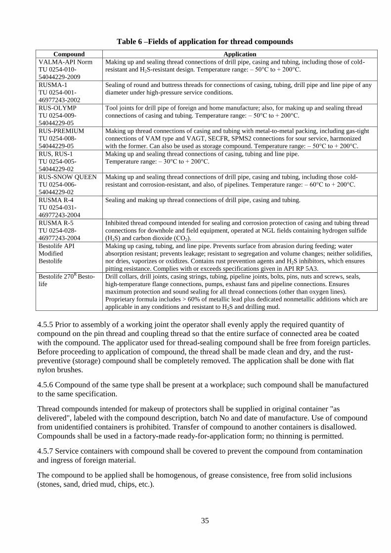
Table 6 –Fields of application for thread compounds
Compound Application
VALMA-API Norm
TU 0254-010-
54044229-2009
Making up and sealing thread connections of drill pipe, casing and tubing, including those of cold-
resistant and H2S-resistant design. Temperature range: – 50°С to + 200°С.
RUSMA-1
TU 0254-001-
46977243-2002
Sealing of round and buttress threads for connections of casing, tubing, drill pipe and line pipe of any
diameter under high-pressure service conditions.
RUS-OLYMP
TU 0254-009-
54044229-05
Tool joints for drill pipe of foreign and home manufacture; also, for making up and sealing thread
connections of casing and tubing. Temperature range: – 50°С to + 200°С.
RUS-PREMIUM
TU 0254-008-
54044229-05
Making up thread connections of casing and tubing with metal-to-metal packing, including gas-tight
connections of VAM type and VAGT, SECFR, SPMS2 connections for sour service, harmonized
with the former. Can also be used as storage compound. Temperature range: – 50°С to + 200°С.
RUS, RUS-1
TU 0254-005-
54044229-02
Making up and sealing thread connections of casing, tubing and line pipe.
Temperature range: – 30°С to + 200°С.
RUS-SNOW QUEEN
TU 0254-006-
54044229-02
Making up and sealing thread connections of drill pipe, casing and tubing, including those cold-
resistant and corrosion-resistant, and also, of pipelines. Temperature range: – 60°С to + 200°С.
RUSMA R-4
TU 0254-031-
46977243-2004
Sealing and making up thread connections of drill pipe, casing and tubing.
RUSMA R-5
TU 0254-028-
46977243-2004
Inhibited thread compound intended for sealing and corrosion protection of casing and tubing thread
connections for downhole and field equipment, operated at NGL fields containing hydrogen sulfide
(Н2S) and carbon dioxide (СО2).
Bestolife API
Modified
Bestolife
Making up casing, tubing, and line pipe. Prevents surface from abrasion during feeding; water
absorption resistant; prevents leakage; resistant to segregation and volume changes; neither solidifies,
nor dries, vaporizes or oxidizes. Contains rust prevention agents and H2S inhibitors, which ensures
pitting resistance. Complies with or exceeds specifications given in API RP 5A3.
Bestolife 270R
Besto-
life
Drill collars, drill joints, casing strings, tubing, pipeline joints, bolts, pins, nuts and screws, seals,
high-temperature flange connections, pumps, exhaust fans and pipeline connections. Ensures
maximum protection and sound sealing for all thread connections (other than oxygen lines).
Proprietary formula includes > 60% of metallic lead plus dedicated nonmetallic additions which are
applicable in any conditions and resistant to H2S and drilling mud.
4.5.5 Prior to assembly of a working joint the operator shall evenly apply the required quantity of
compound on the pin thread and coupling thread so that the entire surface of connected area be coated
with the compound. The applicator used for thread-sealing compound shall be free from foreign particles.
Before proceeding to application of compound, the thread shall be made clean and dry, and the rust-
preventive (storage) compound shall be completely removed. The application shall be done with flat
nylon brushes.
4.5.6 Compound of the same type shall be present at a workplace; such compound shall be manufactured
to the same specification.
Thread compounds intended for makeup of protectors shall be supplied in original container "as
delivered", labeled with the compound description, batch No and date of manufacture. Use of compound
from unidentified containers is prohibited. Transfer of compound to another containers is disallowed.
Compounds shall be used in a factory-made ready-for-application form; no thinning is permitted.
4.5.7 Service containers with compound shall be covered to prevent the compound from contamination
and ingress of foreign material.
The compound to be applied shall be homogenous, of grease consistence, free from solid inclusions
(stones, sand, dried mud, chips, etc.).

36
4.5.8 The compound shall be thoroughly stirred prior to application. Avoid any contact of compound with
skin or its ingress in gastrointestinal tract.
4.5.9 The customer shall be responsible for compliance with the environmental requirements within the
area of work and for proper selection, use and disposal of thread compound.
4.5.10 Use of machinery oil, diesel oil as substitutes for greases, as well as dry makeup shall be
PROHIBITED.
4.6 Monitoring Casing in Service
4.6.1 In operation of casing the following limit loads (without corrosive environment) shall not be
exceeded:
– external pressure;
– pressure containment;
– axial tensile load;
for pipe body:
– without bending
– with bending
(Annexes A1, A2 for pipe made to GOST 632 and ISO 10400 recommendations for pipe made to
API Spec 5CT);
for GOST 632 thread connections:
with round threads:
– without bending
– with bending;
with trapezoidal threads (OTTM, ОТТГ):
– without bending
– with bending;
for makeup torque values (according to Annexes A.3 – A.7).
For thread connections according to specifications (TU):
In accordance with TU requirements and TMK Catalog of API Spec 5B Thread Connections:
with round threads:
– without bending
– with bending;
for makeup torque values (ISO 10405 recommendations);
with buttress threads:
– without bending
– with bending;
(ISO 10400 recommendations).
4.6.2 The following variables shall be monitored during operation:
– thread connection makeup torque;
– axial load;
– hole deviation rate;
– environmental pressure (internal, external);
– ambient temperature;
– environment specific gravity;
– environment corrosive agents.

37
4.7 Care of Casing in Hole
Drill pipe run inside a casing string should be equipped with suitable drill-pipe protectors.
4.8 Recovery of Casing
4.8.1 Breakout tongs should be positioned close to the coupling but not too close since a slight squashing
effect where the tong dies contact the pipe surface cannot be avoided. Keeping a space of ⅓ to ¼ of the
pipe diameter between the tong and the coupling should normally prevent unnecessary friction in the
threads.
4.8.2 Hammering the coupling to facilitate breaking the joint is an injurious practice. If tapping is
required, use only the flat face, never the peen face of the hammer, and under no circumstances should a
sledge hammer be used. Tap lightly near the middle and completely around the coupling, never near the
end nor on the opposite sides only.
4.8.3 Great care should be exercised to disengage all of the thread before lifting the casing out of the
coupling. Do not pull abruptly the casing out of the coupling.
4.8.4 All threads should be cleaned and lubricated or should be coated with a material that will minimize
corrosion. Clean protectors should be placed on the casing before it is laid down.
4.8.5 When casing is being retrieved because of a casing failure, it is imperative to future prevention of
such failures that a thorough metallurgical study be made. Every attempt should be made to retrieve the
failed portion in the "as-failed" condition. When thorough metallurgical analysis reveals some facet of
pipe quality to be involved in the failure, the results of the study should be recorded.
4.9 Basic Recommendations for Prevention of Emergencies
4.9.1 Before proceeding to construction of wells, a degree of risks of emergency failure for casing strings
shall be reviewed. In particular, such risks may be caused by severe service conditions (low temperatures,
corrosive environment, etc.). If required, mitigation arrangements shall be developed.
4.9.2 Strictly comply with the provisions of Section 4 "Good Practice for Operation of Pipe" of this
Manual, API RP 5C1 and ISO 10405, considering these preventive arrangements for mitigation of risks of
emergency failure for casing strings used in construction of wells.
4.9.3 To reduce the emergencies during the works for casing of wells:
– have a good knowledge of mining and geological conditions of well construction, range of potential
problems;
– strictly comply with the requirements of detailed design, current procedural regulations and safety
codes applicable to petroleum and natural gas industry, process flow diagram statement, works
programs; have the above listed documents available at the drill site;
– monitor the condition of borehole and serviceability of equipment and tools;
– know and observe operating procedures for pipe and equipment;
– monitor applied loads;
– make up connections with tongs equipped with a torque gauge;
– implement, in full and in timely manner, arrangements for fault-free working at the drill site;
– make sure that the requirements of Section 4 "Good Practice for Operation of Pipe" of this Manual
are complied with;

38
– loads applied to casing in operation shall not exceed the limit loads according to Annex A,
specification (TU) requirements, recommendations given in "Thread Connections Catalog" (TMK
publication), and ISO 10405, for pipe made to API Spec 5CT with safety factors applied.
To avoid emergencies, running of casing shall be prohibited:
– if the factory marking data are inconsistent with the values stated in the certificate;
– if the inspection results in detection of defects of a magnitude that is greater than allowable;
– in case of improper seating of coupling at the mill (standoff not in conformity with specification
requirements, explicit pipe-to-coupling misalignment, etc.);
– when the pipe wall thickness including the wall thickness at the threaded end in the face-end plane, is
not in compliance with the specification requirements;
– if hydrostatic testing reveals pipe or thread connection leakage.
Investigations of industrial accidents involving pipe should be conducted in accordance with "Guidelines
for investigation of industrial accidents with drill pipe, casing and tubing, and for claim documenting".
5 Transportation and Storage
5.1 Transportation
5.1.1 Transportation of pipe shall be carried out by rail (on open-top freight cars), by truck or by water in
accordance with Shipping Rules and Specifications for Cargo Loading and Fastening applicable to the
specific means of transportation.
5.1.2 Stringers shall be provided across the car or truck body bottom. Pipe bundles shall be provided with
transportation straps.
5.1.3 When carrying pipe on flat wagon, upright posts, wire-tied above the pipe, shall be installed on the
car sides.
5.1.4 For truck transportation, the following precautions shall be taken:
– load pipe on bolsters and tie down with suitable chain at the bolsters;
– load pipe with all couplings facing the same end of the truck.
5.1.5 The bundle weight shall not exceed 5 metric tons, or, at customer's request, 3 metric tons. When
bundling pipe, couplings screwed on pipe shall face the same direction.
5.1.6 Bundling material shall not be used as slinging fixture. The packing shall allow for multiple
transfers of bundles with pipe undamaged.
5.2 Storage
5.2.1 All casing stored at a pipe yard shall rest on racks.
5.2.2 The following categories of pipe shall be stored on individual racks:
a) new pipe received from manufacturers;
b) pipe sorted out by type of reconditioning;
c) reconditioned pipe;

39
d) rejected pipe beyond repair;
e) pipe grouped in sets for forming strings and prepared for delivery to the customer.
5.2.3 Each rack shall accommodate the pipe of the same characteristics: type, nominal diameter, wall
thickness, grade.
5.2.4 The following requirements apply to the racks and the pipe laying:
a) the rack bearing surface shall be horizontal to avoid any inadvertent rolling of pipe; the rack design
shall ensure that the pipe rest on the rack at least at three points of contact, to avoid any inadvertent
rolling down; each rack shall be provided with upright posts;
b) the rack bearing surface should be no less than 500 mm above the ground;
c) pipe should not be stacked higher than 3000 mm;
d) provide wooden strips as separators between successive layers of pipe. Use at least three spacing
strips, 35 – 40 mm thick each.
The strips between layers of pipe shall be coplanar.
5.2.5 Each rack shall be provided with a nameplate containing the specifications of accommodated pipe.
5.2.6 Threads shall be coated by rust-preventive compound and covered with thread protectors.
5.2.7 Storage of acids, alkalis and other corrosive chemicals close to the racks shall be forbidden.
6 Safety Requirements
To ensure safe operation of pipe, make sure that the requirements of the manufacturer's Operation Manual
for the delivered product and other Manufacturer's recommendations, as well as combined corporate
regulations for operation of pipe, duly approved at drilling facilities and consistent with the
Manufacturer's Operation Manual and PB 08-624-03 "Petroleum and Natural Gas Industry Safety Code"
are unconditionally complied with.
7 Manufacturer's Guarantee
The Manufacturer warrants that the pipe and couplings are and remain in conformity to specification
requirements within the period specified in the contract (purchase order), provided the pipe operation and
storage procedures are complied with.

40
Annex A Strength Properties and Makeup Torque Values for Casing Made to GOST 632
Table A.1 – Strength properties of pipe body for GOST 632 pipe
Nominal
diameter,
mm
Wall
thickness,
mm
External pressure limit, MPa Internal pressure limit, MPa Limit tensile loads, kN
Д Е Л М Р Д К Е Л М Р Д К Е Л М Р
1 2 3 4 5 6 7 8 9 10 11 12 13 14 15 16 17 18 19
114
5.2 20.3 - - - - 30.2 - - - - - 666 - - - - -
5.7 24.2 - - - - 33.1 - - - - - 744 - - - - -
6.4 29.5 38.6 42.7 45.9 - 37.2 (36.5) -
(48.0)
54.0 64.2 74.3 - 824 (804) (1058) 1196 1412 1646 -
7.4 36.9 50.3 57.1 62.7 70.1 42.9 (42.3) (55.5) 62.4 74.2 85.9 105.4 940 (920) (1216) 1372 1628 1882 2314
8.6 45.3 63.4 73.4 82.4 95.5 50.0 (49.0) (64.5) 72.5 86.3 99.8 122.5 1078 (1058) (1392) 1568 1862 2156 2646
10.2 - - 93.7 106.9 127.4 - - - 102.3 118.3 145.3 - - - 2176 2530 3098
127
5.6 19.0 - - - - 29.3 - - - - - 804 - - - - -
6.4 24.6 31.1 33.6 35.5 - 33.4 (32.8) (43.2) 48.6 57.7 66.9 - 920 (902) (1176) 1332 1588 1842 -
7.5 32.2 42.7 47.7 51.7 56.6 39.2 (38.5) (50.7) 57.0 67.6 78.3 96.2 1056 (1038) (1372) 1548 1842 2138 2608
9.2 43.0 60.0 69.2 77.4 88.8 48.1 (47.3) (62.2) 69.8 83.0 96.1 117.9 1294 (1274) (1666) 1882 2236 2568 3156
10.7 52.3 74.1 86.7 98.3 116.4 56.0 - 81.3 96.6 111.8 137.2 1490 - 2156 2548 2960 3628
140
6.2 19.3 - - - - 29.5 (28.9) (38.0) 42.7 - - - 980 (960) (1274) 1430 - - -
7.0 24.4 30.7 33.2 35.0 - 33.2 (32.6) (42.9) 48.3 57.4 66.5 - 1098 (1078) (1430) 1608 1902 2216 -
7.7 28.8 37.4 41.3 44.2 47.6 36.6 (36.0) (47.3) 53.1 63.1 73.1 89.7 1216 (1196) (1568) 1764 2078 2412 2960
9.2 37.7 51.7 58.8 64.9 72.8 43.7 (42.9) (56.5) 63.5 75.5 87.4 107.3 1430 (1412) (1842) 2078 2470 2862 3510
10.5 45.2 63.3 73.3 82.4 95.3 49.9 (49.0) (64.5) 72.4 86.2 99.7 122.4 1608 (1588) (2078) 2352 2784 3236 3962
146
6.5 19.4 - - - - 29.5 (29.0) (38.1) 42.9 - - - 1078 (1058) (1392) 1568 - - -
7.0 22.4 27.7 29.8 31.3 - 31.8 (31.3) (41.1) 46.2 63.5 54.9 - 1156 (1136) (1490) 1686 2000 2314 -
7.7 26.7 34.2 37.4 39.7 - 35.0 (34.3) (45.2) 50.8 60.4 69.9 - 1274 (1254) (1646) 1842 2196 2530 -
8.5 31.4 41.6 46.3 50.0 54.5 38.6 (37.9) (49.9) 56.1 66.7 77.2 94.7 1392 (1372) (1804) 2020 2412 2784 3412
9.5 37.1 50.7 57.5 63.2 70.8 43.1 (42.4) (55.8) 62.7 74.5 86.3 105.9 1548 (1510) (2000) 2234 2666 3078 3784
10.7 43.7 61.0 70.4 78.8 90.7 48.6 (47.7) (62.8) 70.6 83.9 97.2 119.2 1726 (1686) (2234) 2510 2980 3452 4236

41
Table A.1 (continued)
1 2 3 4 5 6 7 8 9 10 11 12 13 14 15 16 17 18 19
168
7.3 18.3 21.9 - - - 28.8 (28.8) (37.3) 41.9 49.7 - - 1392 (1372) (1804) 2040 2412 - -
8.0 22.1 27.3 - - - 31.6 (31.0) (40.8) 45.8 54.4 - - 1510 (1490) (1962) 2216 2628 - -
8.9 26.9 34.4 37.6 40.0 42.8 35.1 (34.5) (45.4) 51.0 60.6 70.1 86.1 1686 (1666) (2176) 2450 2922 3372 4138
10.6 35.4 47.9 54.2 59.3 65.9 41.9 (41.1) (54.0) 60.7 72.2 83.5 102.5 1980 (1960) (2568) 2882 3432 3980 4884
12.1 42.6 59.3 68.3 76.3 87.4 47.7 (46.9) (61.7) 69.3 82.4 95.4 117.1 2254 (2216) (2902) 3274 4490 5510
178
5.9 9.8 - - - - 22.1 - - - - - 1216 - - - - -
6.9 14.4 - - - - 25.8 (25.3) (33.3) 37.4 - - - 1412 (1372) (1804) 2038 - - -
8.1 20.3 24.6 26.3 - - 30.3 (29.7) (39.1) 43.9 52.3 - - 1626 (1608) (2118) 2372 2824 - -
9.2 25.9 32.8 35.8 37.9 40.4 34.3 (33.4) (44.4) 49.9 59.3 68.6 84.2 1842 (1824) (2392) 2686 3196 3686 4530
10.4 31.7 42.1 46.9 50.6 55.2 38.8 (38.1) (50.2) 56.4 67.1 77.5 95.2 2078 (2038) (2686) 3020 3568 4138 5080
11.5 36.9 50.2 57.0 62.6 69.9 42.9 (42.2) (55.5) 62.4 74.1 85.8 105.3 2274 (2234) (2942) 3314 3922 4550 5588
12.7 42.3 58.7 67.6 75.4 86.4 47.4 (46.6) (61.3) 68.8 81.9 94.7 116.3 2490 (2450) (3216) 3628 4314 4980 6118
13.7 - 65.6 76.2 85.8 99.8 - - 74.3 88.3 102.2 125.5 - - 3882 4628 5354 6570
15.0 - - 86.9 98.5 116.6 - - - 96.7 111.9 137.4 - - - 4980 5766 7100
194
7.6 14.7 - - - - 26.1 (25.6) (33.6) 37.8 - - - 1686 (1646) (2176) 2450 - - -
8.3 17.9 21.3 22.4 23.2 24.2 28.4 (27.9) (36.8) 41.3 49.1 56.9 69.8 1824 (1804) (2372) 2666 3156 3666 4490
9.5 23.4 29.2 31.6 33.1 35.1 32.5 (32.0) (42.1) 47.3 56.2 65.0 79.9 2078 (2038) (2686) 3020 3588 4158 5118
10.9 29.8 39.0 43.1 46.4 50.2 37.4 (36.7) (48.2) 54.2 64.5 74.6 91.7 2372 (2334) (3058) 3452 4098 4746 5824
12.7 37.5 51.4 58.3 64.3 72.1 43.5 (42.4) (56.3) 63.2 75.1 87.0 106.8 2744 (2686) (3530) 3980 4726 5472 6706
15.1 - - 77.4 87.4 101.9 - - - 89.3 103.4 127.0 - - - 5550 6412 7884
219
6.7 7.9 - - - - 20.3 - - - - - 1686 - - - - -
7.7 11.4 - - - - 23.3 (22.9) (30.2) 33.9 - - - 1940 (1902) (2510) 2824 - - -
8.9 16.0 18.5 19.5 20.1 - 27.0 (26.5) (34.8) 39.2 46.6 53.8 - 2234 (2196) (2196) 2882 3236 4452 -
10.2 21.2 26.0 27.7 29.0 30.5 30.9 (30.4) (39.9) 44.9 53.3 61.8 75.8 2530 (2490) (3274) 3686 4372 5060 6216
11.4 26.1 33.2 36.3 38.4 41.0 34.5 (33.9) (44.6) 50.2 59.6 69.0 84.7 2824 (2764) (3648) 4098 4864 5628 6922
12.7 31.2 41.3 46.0 49.6 54.0 38.5 (37.7) (49.7) 55.9 66.5 76.9 94.4 3118 (3058) (4040) 4530 5392 6236 7648
14.2 - 50.4 57.2 62.8 70.3 43.1 (42.3) (55.6) 62.4 74.3 86.0 105.5 3470 (3392) (4470) 5040 5982 6922 8492

42
Table A.1 (continued)
1 2 3 4 5 6 7 8 9 10 11 12 13 14 15 16 17 18 19
245
7.9 9.2 - - - - 21.5 (21.1) (27.7) 31.2 - - - 2216 (2176) (2882) 3236 - - -
8.9 12.4 13.9 14.5 14.8 - 24.2 (23.7) (31.3) 35.1 41.8 48.2 - 2490 (2450) (3236) 3628 4314 4980 -
10.0 16.2 18.9 19.8 20.5 21.3 27.2 (26.7) (35.1) 39.4 46.9 54.2 66.6 2784 (2744) (3608) 4060 4824 5570 6844
11.1 20.2 24.4 26.1 27.2 28.4 30.1 (29.6) (38.9) 43.7 52.1 60.2 73.9 3078 (3020) (3980) 4470 5334 6158 7570
12.0 23.4 29.3 31.6 33.2 35.1 32.5 (32.0) (42.1) 47.4 56.3 65.1 79.9 3314 (3254) (4294) 4824 5746 6628 8158
13.8 29.9 39.2 43.4 46.7 50.6 37.4 (36.8) (48.4) 54.4 64.7 74.9 91.9 3784 (3726) (4902) 5510 6550 7570 9296
15.9 - - 57.5 63.2 70.8 - - - 74.5 86.3 105.9 - - - 7472 8648 10610
273
7.1 5.1 - - - - 17.3 (17.0) (22.3) 25.1 - - - 2254 (2216) (2902) 3274 - - -
8.9 9.4 10.3 10.6 10.9 - 21.7 (21.3) (27.9) 31.5 37.4 43.2 - 2804 (2744) (3608) 4060 4844 5584 -
10.2 13.1 14.9 15.5 16.0 16.5 17.3 (17.0) (22.3) 25.1 - - - 3169 (3138) (4118) 4648 5510 6374 7924
11.4 17.0 19.9 21.0 21.7 22.5 24.8 (24.3) (32.1) 36.0 42.8 49.5 60.8 3350 (3490) (4588) 5158 6138 7100 8708
12.6 20.9 25.4 27.2 28.3 29.7 27.7 (27.3) (35.8) 40.3 47.8 55.4 67.9 3902 (3844) (5060) 5688 6746 7806 9590
13.8 24.8 31.3 33.8 35.8 37.9 30.6 (30.1) (39.6) 44.5 52.2 61.2 75.1 4256 (4176) (5510) 6198 7354 8512 10454
15.1 - 37.6 41.6 44.5 48.0 33.5 (32.9) (43.3) 48.7 57.9 97.1 82.3 - - 6746 8002 9276 11376
16.5 - - 50.0 54.3 59.7 - - 53.3 63.3 73.3 90.0 - - - 8708 10008 12376
299
8.5 6.6 - - - - 18.9 (18.5) (24.4) 27.4 - - - 2942 (2882) (3784) 4256 - - -
9.5 8.8 - - - - 21.2 (20.8) (27.3) 30.7 36.5 42.3 51.9 3274 (3216) (4216) 4746 5648 6530 8022
11.1 13.0 14.7 15.4 15.8 - 24.7 (24.2) (31.9) 35.9 42.6 49.3 60.6 3804 (3726) (4926) 5510 6550 7590 9316
12.4 16.8 19.6 20.7 21.4 22.3 27.5 (27.1) (35.0) 40.1 47.6 55.1 67.6 4216 (4158) (5452) 6138 7296 8434 10356
14.8 - 30.0 32.4 34.1 36.1 32.9 (32.4) (42.5) 47.8 56.9 65.8 80.7 5000 (4902) (6472) 7256 8630 9982 12258
324
8.5 5.3 - - - - 17.4 - - - - - 3196 - - - - -
9.5 7.2 7.6 7.8 - - 19.5 (19.1) (25.2) 28.2 - - - 3550 (3490) (4588) 5158 - - -
11.0 10.4 11.6 12.0 12.3 - 22.5 (22.2) (29.1) 32.7 38.9 45.0 55.3 4098 (4020) (5294) 5962 7080 8198 10060
12.4 13.9 15.9 16.6 17.1 17.6 25.4 (25.0) (32.8) 37.0 43.9 50.8 62.4 4608 (4510) (5942) 6688 7942 9198 11278
14.0 18.2 21.7 22.9 23.8 24.8 28.7 (28.1) (37.1) 41.7 49.5 57.4 70.4 5178 (5080) (6668) 7512 8924 10316 12670

43
Table A.1 (continued)
1 2 3 4 5 6 7 8 9 10 11 12 13 14 15 16 17 18 19
340
8.4 4.5 - - - - 16.4 - - - - - 3314 - - - - -
9.7 6.7 7.2 7.3 - - 18.9 (18.6) (24.5) 27.5 32.7 - - 3804 (3746) (4922) 5530 6590 - -
10.9 9.0 9.9 10.2 - - 21.3 (20.9) (27.5) 31.0 36.8 - - 4274 (4196) (5510) 6198 7374 - -
12.2 12.0 13.4 13.9 14.3 - 23.8 (23.3) (30.8) 34.6 41.2 47.6 - 4766 (4668) (6158) 6904 8218 9512 -
13.1 14.1 16.3 17.0 17.4 18.0 25.6 (25.1) (33.0) 37.2 44.2 51.2 62.7 5098 (5000) (6590) 7394 8806 10178 12494
14.0 16.5 19.2 20.3 21.0 21.8 27.4 (26.9) (35.4) 39.7 47.3 54.7 67.1 5432 (5334) (7020) 7884 9374 10846 13316
15.4 20.1 24.3 26.0 - - 16.4 - - - - - - - - 10276 11886 14592
Note – Strength property values in parentheses only apply to pipe of Make Б; values without parentheses apply to pipe of both Make A and Б.

44
Table A.2 – Strength derating factors for plain pipe body at bending (λ)
Pipe diameter,
mm
Pipe grade
Д К Е Л М Р
114.3 0.028 0.021 0.019 0.016 0.014 0.011
127.0 0.031 0.023 0.021 0.018 0.016 0.012
139.7 0.034 0.026 0.023 0.020 0.017 0.013
146.1 0.035 0.027 0.024 0.021 0.018 0.014
168.3 0.041 0.031 0.028 0.024 0.021 0.016
177.8 0.043 0.033 0.030 0.025 0.022 0.017
193.7 0.047 0.036 0.032 0.027 0.024 0.019
219.1 0.053 0.040 0.036 0.031 0.027 0.021
244.5 0.059 0.045 0.041 0.034 0.030 0.024
273.1 0.066 0.050 0.046 0.038 0.033 0.026
298.5 0.072 0.055 0.050 0.042 0.036 0.029
323.9 0.078 0.059 0.054 0.046 0.040 0.031
339.7 0.082 0.062 0.057 0.048 0.042
Note: )5,0(1 0
'
n
nn ,
where n’, n – tensile strength safety factor with and without bending, respectively;
0 – pipe deviation rate.

45
Table A.3 – Limit tensile loads and approximate makeup torque values for GOST 632 round thread connections
Pipe
specified diameter
(mm)
Wall thickness
(mm)
Limit tensile loads for casing with short round thread connections (STC) (kN)
Limit tensile loads for casing with long round thread connections (LC) (kN)
Makeup torque values for casing with STC thread connections (N·m)
Makeup torque values for casing with LC thread connections (N·m)
Д К Е Л М Р Д К Е Л М Р Д К Е Л М Р Д К Е Л М Р
1 2 3 4 5 6 7 8 9 10 11 12 13 14 15 16 17 18 19 20 21 22 23 24 25 26
114
5.2 343 - - - - - - - - - - - 1460 1679 1777 1929 2084 2315 - - - - - -
5.7 421 - - - - - - - - - - - 2080 2384 2523 2739 2958 3286 - - - - - -
6.4 490 (480)
(627)
706 - - - 500 - 725 863 1000 - 2290 2628 2781 3019 3261 3622 2279 2614 2767 3004 3244 3603
7.4 (578)
(755)
853 - - - 598 (588)
(774)
872 1039 1206 1480 3347 3839 4063 4411 4764 5292 3068 3520 3725 4044 4368 4852
8.6 (696)
(912)
1019 1216 1412 1726 725 (706)
(931)
1049 1245 1441 1775 3702 4247 4494 4879 5270 5854 3719 4266 4515 4901 5294 5880
10.2 - - - - - - - - 1520 1755 2157 - - - - - - 4129 4736 5012 5441 5877 6528
127
5.6 441 - - - - - - - - - - - 2100 2409 2550 2768 2990 3321 - - - - - -
6.4 539 (529)
(706)
784 - - - 558 - 823 970 1127 - 2652 3042 3219 3495 3775 4193 2642 3030 3207 3481 3760 4177
7.5 666 (675)
(836)
970 1147 - -. 686 (676)
(892)
1000
1196 1382 1696 3122 3581 3790 4114 4444 4936 3329 3818 4041 4387 4738 5263
9.2 (833)
(1098)
1235 1461 1696 2079 882 (863)
(1137)
1284 1520 1765 2167 4278 4907 5193 5638 6090 6764 4604 5281 5589 6068 6554 7280
10.7 - - - - - - 1049 - 1520 1804 2088 2569 - - - - - - 5068 5813 6152 6679 7214 8013
140
6.2 568 (558)
(735)
833 - - - - - - - - - 2523 2894 3063 3325 3592 3990 - - - - - -
7.0 666 (657)
(863)
970 - - - 696 (686)
(902)
1010 1206 1392 - 2920 3349 3544 3848 4156 4616 3090 3544 3751 4072 4398 4885
7.7 755 (745)
(970)
1098 1304 1510 1853 784 (774)
(1010)
1137 1353 1569 1922 3277 3759 3978 4319 4665 5181 3487 4000 4234 4596 4964 5514
9.2 (912)
(1206)
1353 1608 1863 2294 970 (951)
(1255)
1412 1676 1941 2383 4444 5097 5395 5857 6326 7026 4769 5470 5789 6285 6789 7540
10.5 (1068)
(1402)
1578 1873 2167 2667 1127 (1108)
(1461)
1637 1951 2255 2775 4815 5523 5845 6346 6854 7614 5193 5957 6304 6844 7392 8211
146
6.5 637 (627)
(823)
931 - - - - - - - - - 2999 3440 3641 3952 4269 4742 - - - - - -
7.0 706 (696)
(912)
1019 - - - 735 (725)
(951)
1068 1265 1461 - 3212 3684 3899 4232 4572 5078 3442 3949 4176 4537 4900 5443
7.7 794 (774)
(1019)
1147 - - - 823 (813)
(1068)
1196 1431 1657 - 3806 4366 4620 5016 5418 6018 3765 4319 4570 4962 5359 5953
8.5 (872)
(1157)
1294 1539 1784 2196 931 (912)
(1206)
1353 1608 1863 2285 4947 5675 6006 6520 7042 7822 5372 6162 6521 7079 7646 8493
9.5 (1000)
(1314)
1480 1755 2030 2500 1059 (1039)
(1372)
1539 1833 2128 2608 5378 6169 6529 7088 7656 8503 5873 6737 7130 7740 8360 9286
10.7 (1147)
(1510)
1696 2010 2324 2863 1216 (1196)
(1569)
1765 2098 2432 2981 6812 7814 8269 8977 9697 10771 7478 8578 9078 9855 10645 11824
168
7.3 834 (833)
(1098)
1235 1461 - - 882 - 1284 - - - 3465 3974 4206 4566 4932 5478 3687 4229 4476 4859 5248 5829
8.0 931 (951)
(1226)
1373 1638 - - - -
- - - - 3744 4295 4545 4935 5330 5920 4009 4599 4867 5284 5707 6340
8.9 1078 (1059)
(1392))
1569 1863 2157 2647 1127 (1108)
(1461) 1637
1951
2255 2765 4480 5139 5438 5904 6377 7083 5745 6589 6974 7571 8177 9083
10.6 (1294)
(1706)
1922 2285 2638 3246 1382 (1353)
(1784)
2010 2383 2765 3393 6038 6926 7330 7957 8595 9547 6560 7524 7963 8645 9338 10372
12.1 (1500)
(1981)
2226 2538 3059 3756 1598 (1569)
(2069)
2324 2765 3197 3932 7663 8790 9303 10099 10909 12117 8367 9597 10157 11027 11910 13229
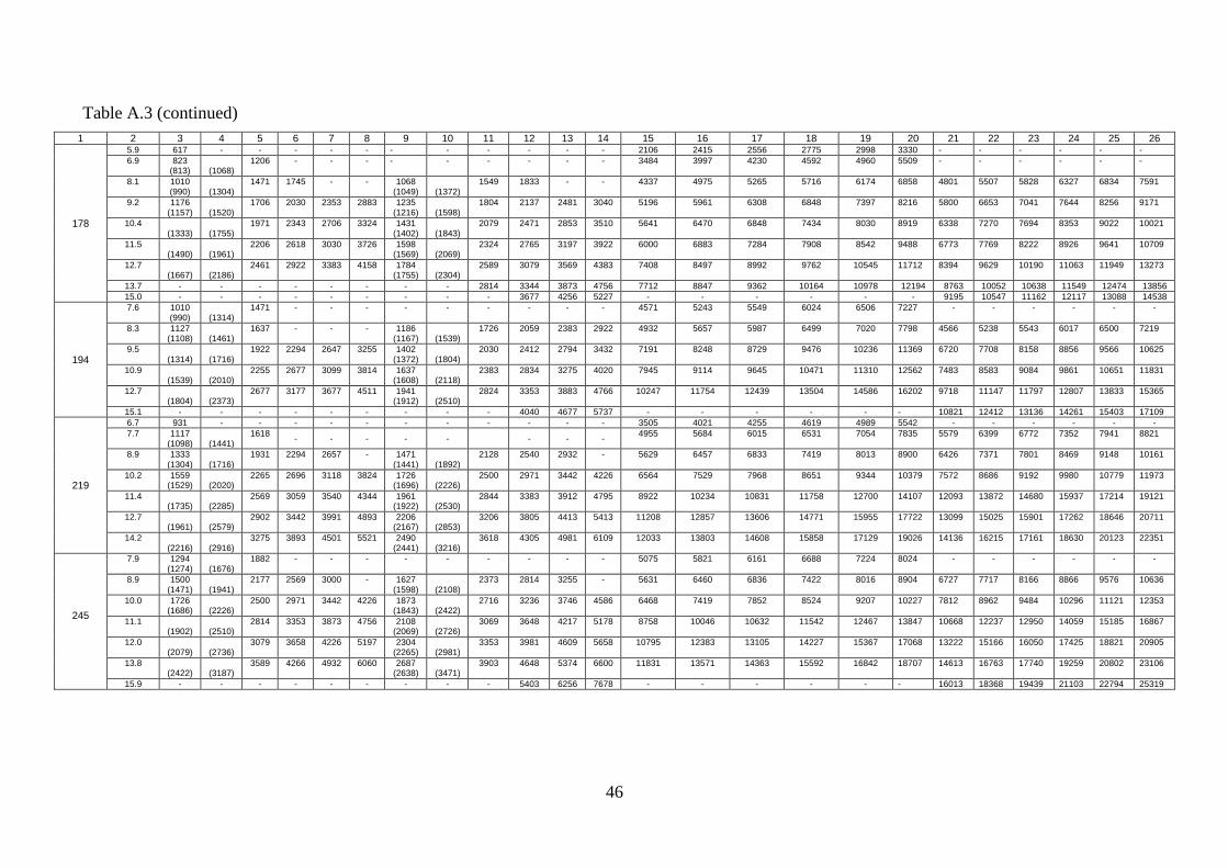
46
Table A.3 (continued)
1 2 3 4 5 6 7 8 9 10 11 12 13 14 15 16 17 18 19 20 21 22 23 24 25 26
178
5.9 617 - - - - - - - - - - - 2106 2415 2556 2775 2998 3330 - - - - - -
6.9 823 (813)
(1068)
1206 - - - - - - - - - 3484 3997 4230 4592 4960 5509 - - - - - -
8.1
1010 (990)
(1304)
1471 1745 - - 1068 (1049)
(1372)
1549 1833 - - 4337 4975 5265 5716 6174 6858 4801 5507 5828 6327 6834 7591
9.2 1176 (1157)
(1520)
1706 2030 2353 2883 1235 (1216)
(1598)
1804 2137 2481 3040 5196 5961 6308 6848 7397 8216 5800 6653 7041 7644 8256 9171
10.4 (1333)
(1755)
1971 2343 2706 3324 1431 (1402)
(1843)
2079 2471 2853 3510 5641 6470 6848 7434 8030 8919 6338 7270 7694 8353 9022 10021
11.5 (1490)
(1961)
2206 2618 3030 3726 1598 (1569)
(2069)
2324 2765 3197 3922 6000 6883 7284 7908 8542 9488 6773 7769 8222 8926 9641 10709
12.7 (1667)
(2186)
2461 2922 3383 4158 1784 (1755)
(2304)
2589 3079 3569 4383 7408 8497 8992 9762 10545 11712 8394 9629 10190 11063 11949 13273
13.7 - - - - - - - - 2814 3344 3873 4756 7712 8847 9362 10164 10978 12194 8763 10052 10638 11549 12474 13856
15.0 - - - - - - - - - 3677 4256 5227 - - - - - - 9195 10547 11162 12117 13088 14538
194
7.6 1010 (990)
(1314)
1471 - - - - - - - - - 4571 5243 5549 6024 6506 7227 - - - - - -
8.3 1127 (1108)
(1461)
1637 - - - 1186 (1167)
(1539)
1726 2059 2383 2922 4932 5657 5987 6499 7020 7798 4566 5238 5543 6017 6500 7219
9.5 (1314)
(1716)
1922 2294 2647 3255 1402 (1372)
(1804)
2030 2412 2794 3432 7191 8248 8729 9476 10236 11369 6720 7708 8158 8856 9566 10625
10.9 (1539)
(2010)
2255 2677 3099 3814 1637 (1608)
(2118)
2383 2834 3275 4020 7945 9114 9645 10471 11310 12562 7483 8583 9084 9861 10651 11831
12.7 (1804)
(2373)
2677 3177 3677 4511 1941 (1912)
(2510)
2824 3353 3883 4766 10247 11754 12439 13504 14586 16202 9718 11147 11797 12807 13833 15365
15.1 - - - - - - - - - 4040 4677 5737 - - - - - - 10821 12412 13136 14261 15403 17109
219
6.7 931 - - - - - - - - - - - 3505 4021 4255 4619 4989 5542 - - - - - -
7.7 1117 (1098)
(1441)
1618 - - - - - - - -
4955 5684 6015 6531 7054 7835 5579 6399 6772 7352 7941 8821
8.9 1333 (1304)
(1716)
1931 2294 2657 - 1471 (1441)
(1892)
2128 2540 2932 - 5629 6457 6833 7419 8013 8900 6426 7371 7801 8469 9148 10161
10.2 1559 (1529)
(2020)
2265 2696 3118 3824 1726 (1696)
(2226)
2500 2971 3442 4226 6564 7529 7968 8651 9344 10379 7572 8686 9192 9980 10779 11973
11.4 (1735)
(2285)
2569 3059 3540 4344 1961 (1922)
(2530)
2844 3383 3912 4795 8922 10234 10831 11758 12700 14107 12093 13872 14680 15937 17214 19121
12.7 (1961)
(2579)
2902 3442 3991 4893 2206 (2167)
(2853)
3206 3805 4413 5413 11208 12857 13606 14771 15955 17722 13099 15025 15901 17262 18646 20711
14.2 (2216)
(2916)
3275 3893 4501 5521 2490 (2441)
(3216)
3618 4305 4981 6109 12033 13803 14608 15858 17129 19026 14136 16215 17161 18630 20123 22351
245
7.9 1294 (1274)
(1676)
1882 - - - - - - - - - 5075 5821 6161 6688 7224 8024 - - - - - -
8.9 1500 (1471)
(1941)
2177 2569 3000 - 1627 (1598)
(2108)
2373 2814 3255 - 5631 6460 6836 7422 8016 8904 6727 7717 8166 8866 9576 10636
10.0 1726 (1686)
(2226)
2500 2971 3442 4226 1873 (1843)
(2422)
2716 3236 3746 4586 6468 7419 7852 8524 9207 10227 7812 8962 9484 10296 11121 12353
11.1 (1902)
(2510)
2814 3353 3873 4756 2108 (2069)
(2726)
3069 3648 4217 5178 8758 10046 10632 11542 12467 13847 10668 12237 12950 14059 15185 16867
12.0 (2079)
(2736)
3079 3658 4226 5197 2304 (2265)
(2981)
3353 3981 4609 5658 10795 12383 13105 14227 15367 17068 13222 15166 16050 17425 18821 20905
13.8 (2422)
(3187)
3589 4266 4932 6060 2687 (2638)
(3471)
3903 4648 5374 6600 11831 13571 14363 15592 16842 18707 14613 16763 17740 19259 20802 23106
15.9 - - - - - - - - - 5403 6256 7678 - - - - - - 16013 18368 19439 21103 22794 25319

47
Table A.3 (continued)
1 2 3 4 5 6 7 8 9 10 11 12 13 14 15 16 17 18 19 20 21 22 23 24 25 26
273
7.1 1157 (1137)
(1490)
1676 - - - - - - - - - 3808 4368 4623 5018 5420 6021 - - - - - -
8.9 1657 (1627)
(2137)
2402 2863 3314 - - - - - - - 5850 6711 7102 7710 8328 9250 - - - - - -
10.2 1941 (1912)
(2510)
2824 3353 3883 4776 - - - - - - 7130 8179 8655 9396 10149 11273 - - - - - -
11.4 2206 (2167)
(2853)
3206 3814 4413 5423 - - - - - - 8523 9776 10346 11232 12132 13476 - - - - - -
12.6 2471 (2422)
(3197)
3589 4266 4932 6060 - - - - - - 9137 10481 11092 12042 13007 14448 - - - - - -
13.8 2726 (2677)
(3530)
3962 4717 5452 6698 - - - - - - 10578 12133 12841 13940 15057 16724 - - - - - -
299
8.5 1676 (1647)
(2167)
2441 - - - - - - - - - 5624 6451 6827 7412 8005 8892 - - - - - -
9.5 1912 (1882)
(2481)
2785 3304 3834 4707 - - - - - - 6740 7731 8182 8883 9594 10657 - - - - - -
11.1 2294 (2255)
(2961)
3334 3962 4589 5629 - - - - - - 8362 9592 10151 11020 11903 13221 - - - - - -
12.4 2599 (2549)
(3363)
3775 4491 5197 6374 - - - - - - 9042 10372 10977 11917 12871 14297 - - - - - -
14.8 (3099)
(4079)
4589 5452 6305 7737 - - - - - - 12890 14786 15648 16988 18349 20382 - - - - - -
324
8.5 1784 - - - - - - - - - - - 5723 6565 6948 7543 8147 9049 - - - - - -
9.5 2039 (2000)
- (2628)
2961 3520 - - - - - - - - 6299 7225 7646 8301 8966 9959 - - - - - -
11.0 2412 (2373)
(3118)
3510 4167 4825 5923 - - - - - - 7716 8851 9367 10169 10984 12201 - - - - - -
12.4 2765 (2716)
(3569)
4011 4776 5521 6776 - - - - - - 11783 13516 14304 15529 16773 18631 - - - - - -
14.0 3157 (3099)
(4079)
4589 5452 6315 7757 - - - - - - 12781 14660 15515 16844 18193 20208 - - - - - -
340
8.4 1824 - - - - - - - - - - - 5583 6404 6778 7358 7947 8828 - - - - - -
9.7 2157 (2118)
(2794)
3138 3736 - - - - - - - - 7243 8308 8792 9545 10310 11452 - - - - - -
10.9 2471 (2432)
(3197)
3589 4275 - - - - - - - - 8265 9481 10033 10893 11765 13068 - - - - - -
12.2 2814 (2755)
(3628)
4079 4854 5619 - - - - - - - 9768 11205 11858 12874 13905 15445 - - - - - -
13.1 3040 (2991)
(3932)
4422 5256 6080 7463 - - - - - - 10244 11751 12436 13501 14583 16198 - - - - - -
14.0 3275 (3216)
(4226)
4756 5648 6541 8031 - - - - - - 10688 12260 12975 14086 15214 16899 - - - - - -
15.4 - - - 6266 7257 8904 - - - - - - 12265 14068 14889 16163 17458 19392 - - - - - -
Note – Strength property values in parentheses only apply to pipe of Make Б; values without parentheses apply to pipe of both Make A and Б.

48
Table A.4 – Strength derating factors for GOST 632 round thread connections at bending (λ)
Pipe diameter,
mm
Pipe grade
Д К Е Л М Р
114.3 0.030 0.023 0.020 0.017 0.014 0.012
127.0 0.034 0.026 0.023 0.020 0.017 0.014
139.7 0.038 0.029 0.025 0.022 0.019 0.015
146.1 0.040 0.030 0.027 0.023 0.020 0.016
168.3 0.046 0.035 0.031 0.027 0.023 0.019
177.8 0.050 0.038 0.033 0.029 0.025 0.020
193.7 0.054 0.042 0.037 0.032 0.027 0.022
219.1 0.066 0.050 0.044 0.037 0.032 0.027
244.5 0.074 0.054 0.050 0.042 0.036 0.030
273.1 0.084 0.064 0.057 0.048 0.041 0.034
298.5 0.095 0.072 0.064 0.054 0.046 0.038
323.9 0.106 0.080 0.072 0.060 0.052 0.043
339.7 0.113 0.086 0.076 0.064 0.055 0.045
351.0 0.122 0.092 0.082 0.069 0.060 -
377.0 0.135 0.102 0.090 0.077 - -
406.4 0.137 0.104 0.093 - - -
426.0 0.160 0.122 0.108 - - -
473.1 0.168 0.128 - - - -
508.0 0.183 - - - - -
Note: )5,0(1 0
'
n
nn ,
where n’, n – tensile strength safety factor with and without bending, respectively;
0 – pipe deviation rate.
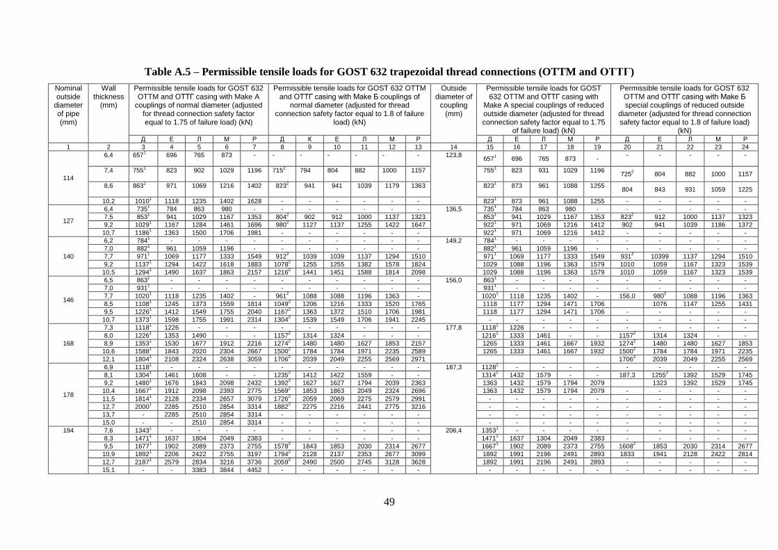
49
Table A.5 – Permissible tensile loads for GOST 632 trapezoidal thread connections (OTTM and ОТТГ)
Nominal outside
diameter of pipe (mm)
Wall thickness
(mm)
Permissible tensile loads for GOST 632 OTTM and ОТТГ casing with Make A
couplings of normal diameter (adjusted for thread connection safety factor equal to 1.75 of failure load) (kN)
Permissible tensile loads for GOST 632 OTTM and ОТТГ casing with Make Б couplings of
normal diameter (adjusted for thread connection safety factor equal to 1.8 of failure
load) (kN)
Outside diameter of
coupling (mm)
Permissible tensile loads for GOST 632 OTTM and ОТТГ casing with
Make A special couplings of reduced outside diameter (adjusted for thread connection safety factor equal to 1.75
of failure load) (kN)
Permissible tensile loads for GOST 632 OTTM and ОТТГ casing with Make Б special couplings of reduced outside
diameter (adjusted for thread connection safety factor equal to 1.8 of failure load)
(kN) Д Е Л М Р Д К Е Л М Р Д Е Л М Р Д Е Л М Р
1 2 3 4 5 6 7 8 9 10 11 12 13 14 15 16 17 18 19 20 21 22 23 24
114
6,4 6571
696 765 873 - - - - - - - 123,8
6571 696 765 873 -
- - - - -
7,4 7551
823 902 1029 1196 715
2 794 804 882 1000 1157 755
1 823 931 1029 1196
7252 804 882 1000 1157
8,6 8631
971 1069 1216 1402 823
2 941 941 1039 1179 1363 823
1 873 961 1088 1255
804 843 931 1059 1225
10,2 10101 1118 1235 1402 1628 - - - - - - 823
1 873 961 1088 1255 - - - - -
127
6,4 7351 784 863 980 - - - - - - - 136,5 735
1 784 863 980 - - - - - -
7,5 8531 941 1029 1167 1353 804
2 902 912 1000 1137 1323 853
1 941 1029 1167 1353 823
2 912 1000 1137 1323
9,2 10291 1167 1284 1461 1696 980
2 1127 1137 1255 1422 1647 922
1 971 1069 1216 1412 902 941 1039 1186 1372
10,7 11861 1363 1500 1706 1981 - - - - - - 922
1 971 1069 1216 1412 - - - - -
140
6,2 7841 - - - - - - - - - - 149,2 784
1 - - - - - - - - -
7,0 8821 961 1059 1196 - - - - - - - 882
1 961 1059 1196 - - - - - -
7,7 9711 1069 1177 1333 1549 912
2 1039 1039 1137 1294 1510 971
1 1069 1177 1333 1549 931
2 10399 1137 1294 1510
9,2 11371 1294 1422 1618 1883 1078
2 1255 1255 1382 1578 1824 1029 1088 1196 1363 1579 1010 1059 1167 1323 1539
10,5 12941 1490 1637 1863 2157 1216
2 1441 1451 1588 1814 2098 1029 1088 1196 1363 1579 1010 1059 1167 1323 1539
146
6,5 8631 - - - - - - - - - - 156,0 863
1 - - - - - - - - -
7,0 9311 - - - - - - - - - - 931
1 - - - - - - - - -
7,7 10201 1118 1235 1402 - 961
2 1088 1088 1196 1363 - 1020
1 1118 1235 1402 - 156,0 980
2 1088 1196 1363
8,5 11081 1245 1373 1559 1814 1049
2 1206 1216 1333 1520 1765 1118 1177 1294 1471 1706 1076 1147 1255 1431
9,5 12261 1412 1549 1755 2040 1167
2 1363 1372 1510 1706 1981 1118 1177 1294 1471 1706 - - - - -
10,7 13731 1598 1755 1991 2314 1304
2 1539 1549 1706 1941 2245 - - - - - - - - - -
168
7,3 11181 1226 - - - - - - - - - 177,8 1118
1 1226 - - - - - - - -
8,0 12261 1353 1490 - - 1157
2 1314 1324 - - - 1216
1 1333 1461 - - 1157
2 1314 1324 - -
8,9 13531 1530 1677 1912 2216 1274
2 1480 1480 1627 1853 2157 1265 1333 1461 1667 1932 1274
2 1480 1480 1627 1853
10,6 15881 1843 2020 2304 2667 1500
2 1784 1784 1971 2235 2589 1265 1333 1461 1667 1932 1500
2 1784 1784 1971 2235
12,1 18041 2108 2324 2638 3059 1706
2 2039 2049 2255 2569 2971 1706
2 2039 2049 2255 2569
178
6,9 11181 - - - - - - - - - - 187,3 1128
1 - - - - - - - - -
8,1 13041 1461 1608 - - 1235
2 1412 1422 1559 - - 1314
1 1432 1579 - - 187,3 1255
2 1392 1529 1745
9,2 14801 1676 1843 2098 2432 1392
2 1627 1627 1794 2039 2363 1363 1432 1579 1794 2079 1323 1392 1529 1745
10,4 16671 1912 2098 2393 2775 1569
2 1853 1863 2049 2324 2696 1363 1432 1579 1794 2079 - - - - -
11,5 18141 2128 2334 2657 3079 1726
2 2059 2069 2275 2579 2991 - - - - - - - - - -
12,7 20001 2285 2510 2854 3314 1882
2 2275 2216 2441 2775 3216 - - - - - - - - - -
13,7 - 2285 2510 2854 3314 - - - - - - - - - - - - - - - -
15,0 - - 2510 2854 3314 - - - - - - - - - - - - - - - -
194
7,6 13431 - - - - - - - - - - 206,4 1353
1 - - - - - - - - -
8,3 14711 1637 1804 2049 2383 - - - - - - 1471
1 1637 1304 2049 2383 - - - - -
9,5 16771 1902 2089 2373 2755 1578
2 1843 1853 2030 2314 2677 1667
1 1902 2089 2373 2755 1608
2 1853 2030 2314 2677
10,9 18921 2206 2422 2755 3197 1794
2 2128 2137 2353 2677 3099 1892 1991 2196 2491 2893 1833 1941 2128 2422 2814
12,7 21871 2579 2834 3216 3736 2059
2 2490 2500 2745 3128 3628 1892 1991 2196 2491 2893 - - - - -
15,1 - - 3383 3844 4452 - - - - - - - - - - - - - - - -

50
Table A.5 (continued)
1 2 3 4 5 6 7 8 9 10 11 12 13 14 15 16 17 18 19 20 21 22 23 24
219
7,7 15491 - - - - - - - - - - 231,8 1549
1 - - - - - - - - -
8,9 17851 2000 2216 2520 - 1686
2 1892 1951 2157 2451 -
3295
17851 2000 2216 2520 - 1716
2 1951 2157 2451 -
10,2 20301 2314 2569 2922 3393 1922
2 2186 2245 2500 2844 2030
1 2295 2530 2873 3334 1951
2 2235 2461 2794 3236
11,4 22551 2520 2893 3295 3815 2128
2 2392 2451 2814 3197 3707 2187 2295 2530 2873 3334 2128 2235 2461 2794 3236
12,7 25001 2903 3236 3687 4266 2363
2 2745 2824 3148 3579 4148 2187 2295 2530 2873 3334 2128 2235 2461 2794 3236
14,2 - 3256 3628 4128 4786 26182 3089 3857 3530 4011 4658 - - - - - 2128 2235 2461 2794 3236
245
7,9 1755 - - - - - - - - - - 257,2
1755 - - - - - - - - -
8,9 20001 2246 2491 2824 - - - - - - - 2000
1 2246 2481 2824 - 1922
2 2186 2422 2745 -
10,0 22361 2540 2824 3216 3726 1882
2 2118 2186 2422 2745 3618 2236
1 2540 2814 3197 3707 2147
2 2471 2736 3118 3608
11,1 24711 2834 3158 3589 4168 2108
2 2402 2471 2745 3118 4050 2432 2559 2814 3197 3707 2363 2490 2736 3118 3608
12,0 26571 3079 3432 3903 4521 2334
2 2677 2755 3069 3491 4393 2432 2559 2814 3197 3707 2363 2490 2736 3118 3608
13,8 30401 3560 3962 4511 5227 2510
2 2902 2991 3334 3795 5080 - - - - -
15,9 - - 4580 5197 6041 - - - - - -
273
8,9 2206 2491 2795 3177 - 21182 2334 2412 2716 3089 - 285,3 2206 2491 2795 3177 - 2147 2412 2716 3089 -
10,2 2550 2873 3236 3687 4276 24122 2696 2794 3148 3579 4158 2550 2854 3138 3569 4138 2461
2 2775 3049 3471 4020
11,4 28441 3226 3648 4148 4815 2687
2 3030 3138 3550 4040 4677 2716 2854 3138 3569 4138 2638 2775 3049 3471 4020
12,6 31281 3579 4050 4609 5345 2951
2 3373 3481 3932 4481 5197 2716 2854 3138 3569 4138 2638 2775 3049 3471 4020
13,8 34031 3942 4452 5070 5884 - - - - - - - - - - - - - - - -
15,1 - 4325 4884 5560 6453 - - - - - - - - - - - - - - - -
16,5 - - 5315 6080 7051 - - - - - - - - - - - - - - - -
299
8,5 2285 - - - - - - - - - - - - - - - - - - - -
9,5 2569 - - - - 2471 2726 2834 3197 3481 - - - - - - - - - - -
11,1 3040 3432 3873 4217 - 28732 3216 3334 3765 4099 - - - - - - - - - - -
12,4 33831 3854 4354 4736 5776 3197
2 3618 3746 4236 4609 5609 - - - - - - - - - -
14,8 - 4609 5197 5943 6943 - - - - - - - - - - - - - - - -
324
9,5 2795 3158 3579 - - 2677 2961 3079 3481 3962 - - - - - - - - - - -
11,0 3265 3697 4177 4766 - 30992 3461 3589 4060 4638 - - - - - - - - - - -
12,4 36871 4187 4746 5413 6286 2677 2961 3079 3481 3962 - - - - - - - - - - -
14,0 41381 4746 5364 6119 7139 - - - - - 6119 - - - - - - - - - -
340
9,7 3001 3393 3844 - - 2873 3187 3304 3736 - - - - - - - - - - - -
10,9 3383 3844 4344 - - 32262 3608 3736 4226 - - - - - - - - - - - -
12,2 38051 4325 5031 5580 - 3599
2 4060 4207 4756 5423 - - - - - - - - - - -
13,1 40791 4658 5276 6021 7002 - - - - - - - - - - - - - - - -
14,0 43441 4991 5649 6453 7512 - - - - - - - - - - - - - - - -
15,4 - - 6208 7080 8287 - - - - - - - - - - - - - - - -
Notes: For Make A pipe 1 – permissible loads at which stresses in the pipe body reach 0.8 of the yield strength (safety factor = 1.25) For Make Б pipe 2 – permissible loads at which stresses in the pipe body reach 0.77 of the yield strength (safety factor = 1.3) The permissible tensile loads given in this Annex apply to vertical holes and holes with deviation rate up to 3.5°
per 10 m.

51
Table A.6 – Reduction in permissible tensile load for GOST 632 trapezoidal threads at bending
Diameter (mm) Rate of deviation (°/10 m)
≤ 3 ≤ 5
114.3 – 168.3 0 0
177.8 – 340.0 0 by 10%
Table A.7 – Approximate makeup torque values for casing with GOST 632 trapezoidal thread connections (OTTM, ОТТГ)
Nominal outside
diameter (mm)
Wall thickness
(mm)
Makeup torque values for casing with GOST 632 OTTM trapezoidal thread connections (N∙m)
Makeup torque values for casing with GOST 632 ОТТГ trapezoidal thread connections (N∙m)
Pipe grade Pipe grade
Д К Е Л М Р Д К Е Л М Р
1 2 3 4 5 6 7 8 9 10 11 12 13 14
114.3
5,7 4242 4866 5150 5591 6039 6708 - - - - - -
6,4 4791 5496 5816 6314 6820 7575 - - - - - -
7,4 5963 6840 7239 7859 8489 9429 - - - - - -
8,6 6715 7703 8152 8850 9559 10618 5072 5181 5235 5325 5425 5588
10,2 7545 8655 9159 9943 10740 11929 6077 6250 6337 6481 6639 6899
127.0
6,4 5062 5807 6146 6672 7206 8005 - - - - - -
7,5 5878 6743 7136 7747 8368 9295 - - - - - -
9,2 7549 8660 9165 9949 10747 11937 5801 5947 6020 6142 6276 6495
10,7 8369 9600 10160 11030 11914 13233 6804 7023 7133 7315 7516 7845
139.7
6,2 5110 5862 6203 6734 7274 8080 - - - - - -
7,0 6035 6922 7326 7953 8590 9542 - - - - - -
7,7 6864 7873 8332 9046 9771 10853 - - - - - -
9,2 7912 9075 9605 10427 11262 12510 6068 6226 6305 6437 6582 6819
10,5 8673 9948 10528 11429 12345 13712 7001 7228 7341 7530 7738 8078
146.1
6,5 5798 6651 7039 7641 8254 9168 - - - - - -
7,0 6279 7202 7622 8275 8938 9928 - - - - - -
7,7 7533 8641 9145 9928 10724 11911 - - - - - -
8,5 8250 9463 10015 10873 11744 13044 6308 6458 6533 6659 6797 7023
9,5 9062 10394 11000 11942 12899 14328 6829 7010 7100 7251 7417 7688
10,7 9930 11390 12054 13086 14135 15700 7820 8070 8194 8402 8631 9005
168.3
7,3 6832 7836 8293 9003 9725 10802 - - - - - -
8,0 7467 8566 9065 9841 10630 11807 - - - - - -
8,9 8214 9422 9971 10825 11692 12987 6364 6554 6648 6806 6980 7263
10,6 10299 11813 12502 13572 14660 16283 8141 8421 8561 8794 9050 9470
12,1 11303 12966 13722 14897 16090 17872 10450 11150 11501 12084 12726 13777

52
Table 7 (continued)
1 2 3 4 5 6 7 8 9 10 11 12 13 14
177.8
6.9 6500 7456 7890 8566 9252 10277 - - - - - -
8.1 7592 8709 9217 10006 10808 12005
- - - - - -
9.2 9231 10589 11206 12166 13140 14596 - - - - - -
10.4 10138 11629 12307 13360 14431 16029 8021 8295 8432 8661 8913 9325
11.5 10871 12470 13197 14327 15475 17189 8955 9314 9494 9793 10123 10662
12.7 11583 13286 14061 15265 16488 18314 9932 10396 10628 11014 11439 12135
13.7 12115 13897 14708 15967 17246 19156 10763 11323 11604 12071 12585 13426
15.0 12739 14612 15464 16788 18133 20142 11883 12583 12933 13516 14157 15207
193.7
7.6 7987 9161 9695 10525 11369 12628 - - - - - -
8.3 8726 10010 10593 11500 12422 13797 - - - - - -
9.5 10773 12358 13078 14198 15336 17034 7345 7575 7689 7880 8090 8434
10.9 12062 13836 14642 15896 17170 19071 8995 9331 9500 9780 10089 10594
12.7 13492 15476 16379 17781 19206 21333 10974 11477 11728 12147 12607 13361
15.1 15089 17308 18317 19885 21479 23857 13451 14224 14610 15253 15961 17120
219.1
7.7 8826 10124 10714 11632 12564 13955 - - - - - -
8.9 10241 11748 12432 13497 14578 16193 6426 6632 6734 6906 7094 7402
10.2 12133 13917 14729 15990 17271 19184 8431 8739 8893 9151 9433 9896
11.4 13890 15933 16862 18305 19772 21962 10329 10749 10959 11309 11694 12324
12.7 15089 17308 18318 19886 21479 23858 11459 12017 12297 12762 13274 14112
14.2 16327 18728 19820 21517 23241 25815 13768 14510 14881 15499 16179 17291
244.5
7.9 9077 10412 11019 11962 12920 14351 - - - - - -
8.9 10245 11752 12437 13502 14584 16199 6497 6728 6844 7037 7249 7597
10.0 11930 13685 14482 15722 16982 18863 8272 8601 8765 9038 9339 9832
11.1 13602 15602 16512 17926 19362 21506 10083 10523 10743 11110 11513 12173
12.0 14468 16596 17564 19068 20595 22876 11266 11809 12080 12532 13029 13843
13.8 16022 18379 19451 21116 22808 25334 13550 14328 14717 15365 16078 17245
15.9 17585 20172 21348 23176 25033 27805 16128 17231 17783 18702 19713 21367
273.1
8.9 10235 11740 12425 13489 14569 16183 6563 6823 6953 7170 7408 7798
10.2 12660 14522 15368 16684 18021 20017 8974 9364 9560 9885 10243 10828
11.4 13895 15938 16867 18312 19779 21969 10641 11173 11439 11882 12370 13167
12.6 15012 17220 18223 19784 21369 23736 12256 12949 13296 13873 14509 15548
13.8 16027 18384 19456 21121 22814 25340 13833 14708 15145 15874 16676 17988
15.1 17026 19530 20669 22439 24237 26921 15515 16609 17156 18068 19070 20711
16.5 18002 20650 21854 23725 25626 28464 17310 18667 19345 20475 21719 23754

53
Table 7 (continued)
1 2 3 4 5 6 7 8 9 10 11 12 13 14
323.9
8.5 9932 11393 12057 13090 14138 15704 - - - - - -
9.5 11077 12706 13447 14598 15768 17514 - - - - - -
11 13766 15790 16711 18142 19595 21765 - - - - - -
12.4 15159 17388 18402 19977 21578 23968 - - - - - -
14 16576 19014 20123 21846 23596 26209 - - - - - -
Note – Makeup torque values listed in this Table shall be only considered a guide and may be adjusted in the course of acquisition of statistical data for specific thread connection assembly conditions.
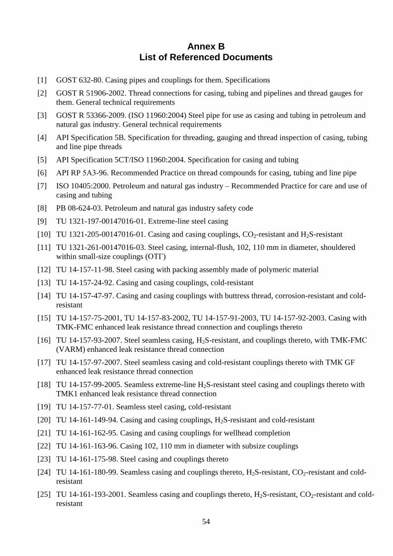
54
Annex B List of Referenced Documents
[1] GOST 632-80. Casing pipes and couplings for them. Specifications
[2] GOST R 51906-2002. Thread connections for casing, tubing and pipelines and thread gauges for
them. General technical requirements
[3] GOST R 53366-2009. (ISO 11960:2004) Steel pipe for use as casing and tubing in petroleum and
natural gas industry. General technical requirements
[4] API Specification 5B. Specification for threading, gauging and thread inspection of casing, tubing
and line pipe threads
[5] API Specification 5CT/ISO 11960:2004. Specification for casing and tubing
[6] АРI RP 5А3-96. Recommended Practice on thread compounds for casing, tubing and line pipe
[7] ISO 10405:2000. Petroleum and natural gas industry – Recommended Practice for care and use of
casing and tubing
[8] PB 08-624-03. Petroleum and natural gas industry safety code
[9] TU 1321-197-00147016-01. Extreme-line steel casing
[10] TU 1321-205-00147016-01. Casing and casing couplings, CO2-resistant and H2S-resistant
[11] TU 1321-261-00147016-03. Steel casing, internal-flush, 102, 110 mm in diameter, shouldered
within small-size couplings (ОТГ)
[12] TU 14-157-11-98. Steel casing with packing assembly made of polymeric material
[13] TU 14-157-24-92. Casing and casing couplings, cold-resistant
[14] TU 14-157-47-97. Casing and casing couplings with buttress thread, corrosion-resistant and cold-
resistant
[15] TU 14-157-75-2001, TU 14-157-83-2002, TU 14-157-91-2003, TU 14-157-92-2003. Casing with
TMK-FMC enhanced leak resistance thread connection and couplings thereto
[16] TU 14-157-93-2007. Steel seamless casing, H2S-resistant, and couplings thereto, with ТМК-FМС
(VARM) enhanced leak resistance thread connection
[17] TU 14-157-97-2007. Steel seamless casing and cold-resistant couplings thereto with ТМК GF
enhanced leak resistance thread connection
[18] TU 14-157-99-2005. Seamless extreme-line H2S-resistant steel casing and couplings thereto with
TMK1 enhanced leak resistance thread connection
[19] TU 14-157-77-01. Seamless steel casing, cold-resistant
[20] TU 14-161-149-94. Casing and casing couplings, H2S-resistant and cold-resistant
[21] TU 14-161-162-95. Casing and casing couplings for wellhead completion
[22] TU 14-161-163-96. Casing 102, 110 mm in diameter with subsize couplings
[23] TU 14-161-175-98. Steel casing and couplings thereto
[24] TU 14-161-180-99. Seamless casing and couplings thereto, H2S-resistant, CO2-resistant and cold-
resistant
[25] TU 14-161-193-2001. Seamless casing and couplings thereto, H2S-resistant, CO2-resistant and cold-
resistant

55
[26] TU 14-161-204-2002. Steel casing, cold-resistant, and couplings thereto for gas and gas-condensate
fields
[27] TU 14-162-13-95. Seamless casing with buttress thread connection and couplings thereto
[28] TU 14-162-41-98. Seamless casing, enhanced leak resistance, size 324 mm, with ОТТГ thread
connection, and couplings thereto
[29] TU 14-162-53-2004. Casing ТТL-01 and couplings thereto for directional and horizontal holes with
hole deviation rate up to 5°/10 m
[30] TU 14-162-102-2000. Longitudinal electric-welded casing and couplings thereto
[31] TU 14-3-514-76. Casing and casing couplings
[32] TU 14-3-714-78, TU 14-157-76-2001. Plain-end extreme-line casing with ОГ1М thread connection
[33] TU 14-ZR-29-2007. Steel casing, seamless and electric-welded, and couplings thereto, heavy-duty,
with buttress thread connection
[34] TU 14-ZR-76-2004. Casing and casing couplings, cold-resistant
[35] TU 14-ZR-82-2005. Casing and casing couplings, cold-resistant for OAO GAZPROM
[36] TU 39.0147016-63-96. Casing and casing couplings with buttress thread
[37] TU 39-0147016-106-2000. Steel casing, internal-flush, and couplings thereto (ОТУ)
[38] Design manual for oil and gas well casing strings. Moscow, 1997.
[39] Recommended Practice for selection of thread connections for casing, drill pipe and tubing used in
construction of slanted holes, horizontal holes and downhole splitters
[40] Recommended Practice for operation and rejecting inspection of casing at petroleum and natural
gas production facilities. Moscow, 2000
Guidelines for investigation of industrial accidents with drill pipe, casing and tubing, and for claim
documenting. Moscow, 1997
[41] API RP 5C1. Recommended Practice for care and use of casing and tubing
[42] API RP 5B1. Recommended Practice for gauging and inspection of casing, tubing and line pipe
threads
[43] API RP 5A3. Recommended Practice on thread compounds for casing, tubing and line pipe, 2nd
Edition. July 2003.
[44] ISO 10400. Petroleum and natural gas industry – Equations and calculations for the properties of
casing, tubing, drill pipe and line pipe used as casing or tubing
[45] Catalog of thread connections (TMK publication)
[46] Guidelines for investigation of industrial accidents with drill pipe, casing and tubing, and for claim
documenting. Moscow, 1997

56
Abbreviations Used in This Document
OTTM
casing with trapezoidal thread and couplings thereto
ОТТГ
casing with trapezoidal thread connection, enhanced leak resistance
BC buttress thread connection
ОТУ
buttress thread connection with "metal-to-metal" packing
UPTO and KO administration for equipment maintenance, service, procurement and integration
CBPO
central production support shop
CTB central pipe yard
AKO
automatic casing tongs
AKB
automatic drill pipe tongs
ОТГ enhanced leak resistance casing with radial end-face packing
ОГ1М
enhanced leak resistance casing