Pipe - Chatham Steel
11
PIPE
Transcript of Pipe - Chatham Steel

PIP
E
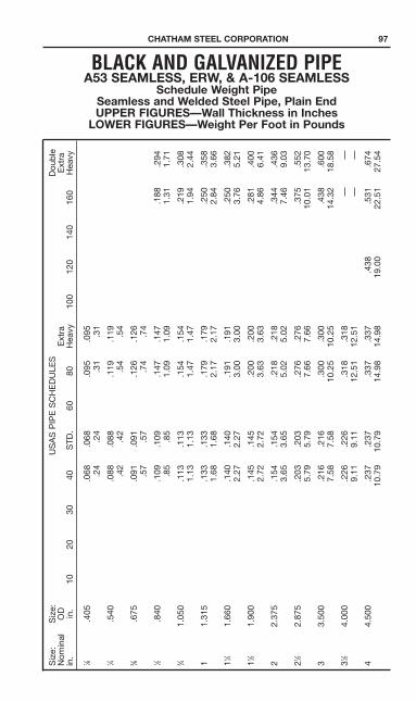
BLACK AND GALVANIZED PIPEA53 SEAMLESS, ERW, & A-106 SEAMLESS
Schedule Weight PipeSeamless and Welded Steel Pipe, Plain EndUPPER FIGURES—Wall Thickness in InchesLOWER FIGURES—Weight Per Foot in Pounds
Siz
e:S
ize:
US
AS
PIP
ES
CH
ED
ULE
SD
oub
leN
omin
alO
DE
xtra
Ext
rain
.in
.10
2030
40S
TD.
6080
Hea
vy10
012
014
016
0H
eavy
1 ⁄8.4
05.0
68.0
68.0
95.0
95.2
4.2
4.3
1.3
11 ⁄4
.540
.088
.088
.119
.119
.42
.42
.54
.54
3 ⁄8.6
75.0
91.0
91.1
26.1
26.5
7.5
7.7
4.7
41 ⁄2
.840
.109
.109
.147
.147
.188
.294
.85
.85
1.09
1.09
1.31
1.71
3 ⁄41.
050
.113
.113
.154
.154
.219
.308
1.13
1.13
1.47
1.47
1.94
2.44
11.
315
.133
.133
.179
.179
.250
.358
1.68
1.68
2.17
2.17
2.84
3.66
11 ⁄41.
660
.140
.140
.191
.191
.250
.382
2.27
2.27
3.00
3.00
3.76
5.21
11 ⁄21.
900
.145
.145
.200
.200
.281
.400
2.72
2.72
3.63
3.63
4.86
6.41
22.
375
.154
.154
.218
.218
.344
.436
3.65
3.65
5.02
5.02
7.46
9.03
21 ⁄22.
875
.203
.203
.276
.276
.375
.552
5.79
5.79
7.66
7.66
10.0
113
.70
33.
500
.216
.216
.300
.300
.438
.600
7.58
7.58
10.2
510
.25
14.3
218
.58
31 ⁄24.
000
.226
.226
.318
.318
——
9.11
9.11
12.5
112
.51
——
44.
500
.237
.237
.337
.337
.438
.531
.674
10.7
910
.79
14.9
814
.98
19.0
022
.51
27.5
4
CHATHAM STEEL CORPORATION 97

98 CHATHAM STEEL CORPORATION
Siz
e:S
ize:
US
AS
PIP
ES
CH
ED
ULE
SD
oub
leN
omin
alO
DE
xtra
Ext
rain
.in
.10
2030
40S
TD.
6080
Hea
vy10
012
014
016
0H
eavy
55.
563
.258
.258
.375
.375
.500
.625
.750
14.6
214
.62
20.7
820
.78
27.0
432
.96
38.5
5
66.
625
.280
.280
.432
.432
.562
.719
.864
18.9
718
.97
28.5
728
.57
36.3
945
.35
53.1
6
88.
625
.250
.277
.322
.322
.406
.500
.500
.594
.719
.812
.906
.875
——
22.3
624
.70
28.5
528
.55
35.6
443
.39
43.3
950
.95
60.7
167
.76
74.6
972
.42
1010
.750
.250
.307
.365
.365
.500
.594
.500
.719
.844
1.00
01.
125
——
—28
.04
34.2
440
.48
40.4
854
.74
64.4
354
.74
77.0
389
.29
104.
1311
5.64
—
1212
.750
.250
.330
.406
.375
.562
.688
.500
.844
1.00
01.
125
1.31
2—
——
——
——
——
33.3
843
.77
53.5
249
.56
73.1
588
.63
65.4
210
7.32
125.
4913
9.67
160.
27—
1414
.000
.250
.312
.375
.438
.375
.594
.750
.500
.938
1.09
41.
250
1.40
6—
36.7
145
.61
54.5
763
.44
54.5
785
.05
106.
1372
.09
130.
8515
0.79
170.
2118
9.11
—
1616
.000
.250
.312
.375
.500
.375
.656
.844
.500
1.03
11.
219
1.43
81.
594
—42
.05
52.2
762
.58
82.7
762
.58
107.
5013
6.61
82.7
716
4.82
192.
4322
3.64
245.
25—
1818
.000
.250
.312
.438
.562
.375
.750
.938
.500
1.15
61.
375
1.56
21.
781
—47
.39
58.9
482
.15
04.6
770
.59
138.
1717
0.92
93.4
520
7.96
244.
1427
4.22
308.
50—
2020
.000
.250
.375
.500
.594
.375
.812
1.03
1.5
001.
281
1.50
01.
750
1.96
9—
52.7
378
.60
104.
1312
3.11
78.6
016
6.40
208.
8710
4.13
256.
1029
6.37
341.
0937
9.17
—
2222
.000
.250
.375
.500
—.3
75.8
751.
125
.500
1.37
51.
625
1.87
52.
125
—58
.07
86.6
111
4.81
—86
.61
197.
4125
0.82
114.
8130
2.88
354.
5140
3.00
451.
06—
2424
.000
.250
.375
.562
.688
.375
.969
1.21
9.5
001.
531
1.81
22.
062
2.34
4—
63.4
194
.62
140.
6817
1.29
94.6
223
8.35
296.
5812
5.49
367.
3942
9.39
483.
1254
2.13
—
CONTINUATIONOFPAGE97
BLACK AND GALVANIZED PIPEA53 SEAMLESS, ERW, & A-106 SEAMLESS
Schedule Weight PipeSeamless and Welded Steel Pipe, Plain EndUPPER FIGURES—Wall Thickness in InchesLOWER FIGURES—Weight Per Foot in Pounds

CHATHAM STEEL CORPORATION 99

100 CHATHAM STEEL CORPORATION
PIPE SPECIFICATIONSSPECIFICATION A53 Sizes 1⁄8"—26" Std., XS and XXS, A.N.S.I. Schedules 10
through 160—Other sizes subject to inquiry.
Scope Covers seamless and welded BLACK and hot-dipped galvanizednominal (average) wall pipe for coiling, bending, flanging and otherspecial purposes and is suitable for welding. CONTINUOUS WELDpipe is not intended for flanging (rail back operation to form flangeusing pipe wall).Purpose for which pipe is intended should be stated on order.
Kinds of Steel Open-hearth Basic-oxygenPermitted For Electric-furnacePipe Material
Hot-Dipped Sets standards for coating of pipe with zinc inside and outside by theGalvanizing the hot-dipped process. Weight of coating must not average less than
1.8 oz. per square foot and not less than 1.6 oz. per square foot.
Permissible Same as A120.Variationsin WallThickness
Chemical Type S (Seamless pipe) & Type E (electric weld)
Requirements Open-Hearth, Electric- Composition — Max %Furnace or Basic Oxygen C Mn P S
Grade A 0.25 0.95 0.05 0.06Grade B 0.30 1.20 0.05 0.06
Type F (furnace-welded pipe)Open-Hearth, Electric- Composition—Max %
Furance or Basic Oxygen C Mn P S— — 0.08 0.06
Tensile Continuous Weld (furnace-welded) Acid- O.H., Basic Oxygen
Requirements Bessemer or Elec. Furn.Tensile Strength min., psi …………………………………………50,000 45,000Yield Point min., psi…………………………………………………30,000 25,000Seamless or Electric-Weld Grade A Grade BTensile Strength min., psi …………………………………………48,000 60,000Yield Point min., psi…………………………………………………30,000 35,000
Hydrostatic Hydrostatic inspection test pressures for plain end and threaded andTesting coupled pipe are specified.
Hydrostatic pressure shall be maintained for not less than 5 secondsfor all sizes of seamless and electric-weld pipe.
CHATHAM STEEL CORPORATION 101
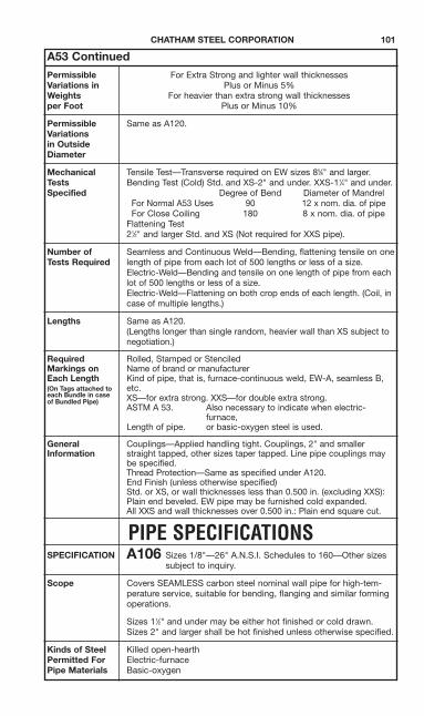
A53 ContinuedPermissible For Extra Strong and lighter wall thicknessesVariations in Plus or Minus 5%Weights For heavier than extra strong wall thicknessesper Foot Plus or Minus 10%
Permissible Same as A120.Variationsin OutsideDiameter
Mechanical Tensile Test—Transverse required on EW sizes 85⁄8" and larger.Tests Bending Test (Cold) Std. and XS-2" and under. XXS-11⁄4" and under.Specified Degree of Bend Diameter of Mandrel
For Normal A53 Uses 90 12 x nom. dia. of pipeFor Close Coiling 180 8 x nom. dia. of pipe
Flattening Test21⁄2" and larger Std. and XS (Not required for XXS pipe).
Number of Seamless and Continuous Weld—Bending, flattening tensile on oneTests Required length of pipe from each lot of 500 lengths or less of a size.
Electric-Weld—Bending and tensile on one length of pipe from eachlot of 500 lengths or less of a size.Electric-Weld—Flattening on both crop ends of each length. (Coil, incase of multiple lengths.)
Lengths Same as A120.(Lengths longer than single random, heavier wall than XS subject tonegotiation.)
Required Rolled, Stamped or StenciledMarkings on Name of brand or manufacturerEach Length Kind of pipe, that is, furnace-continuous weld, EW-A, seamless B,(On Tags attached to etc.each Bundle in case XS—for extra strong. XXS—for double extra strong.of Bundled Pipe)
ASTM A 53. Also necessary to indicate when electric-furnace,
Length of pipe. or basic-oxygen steel is used.
General Couplings—Applied handling tight. Couplings, 2" and smallerInformation straight tapped, other sizes taper tapped. Line pipe couplings may
be specified.Thread Protection—Same as specified under A120.End Finish (unless otherwise specified)Std. or XS, or wall thicknesses less than 0.500 in. (excluding XXS):Plain end beveled. EW pipe may be furnished cold expanded.All XXS and wall thicknesses over 0.500 in.: Plain end square cut.
PIPE SPECIFICATIONSSPECIFICATION A106 Sizes 1/8"—26" A.N.S.I. Schedules to 160—Other sizes
subject to inquiry.
Scope Covers SEAMLESS carbon steel nominal wall pipe for high-tem-perature service, suitable for bending, flanging and similar formingoperations.
Sizes 11⁄2" and under may be either hot finished or cold drawn.Sizes 2" and larger shall be hot finished unless otherwise specified.
Kinds of Steel Killed open-hearthPermitted For Electric-furnacePipe Materials Basic-oxygen

102 CHATHAM STEEL CORPORATION
A106 Continued
Hot-Dipped Not covered in specification.Galvanizing
Permissible Same as A120.Variations inWall Thickness
Chemical Grade A Grade B Grade CCarbon max. % ………………0.25 0.30 0.35Manganese % ……………0.27 to 0.93 0.29 to 1.06 0.29 to 1.06Phosphorus, max. % …………0.048 0.048 0.048Sulfur, max. % …………………0.058 0.058 0.058Silicon, min. % …………………0.10 0.10 0.10
Tensile SeamlessRequirements Grade A Grade B Grade C
Tensile Strength min., psi 48,000 60,000 70,000Yield Point min., psi 30,000 35,000 40,000
Hydrostatic Inspection test pressures produce a stress in the pipe wall equal toTesting 60% of minimum specified Yield Point at room temperature. Maximum
Pressures are not to exceed 2500 psi for sizes 3" and under, and2800 psi for the larger sizes.Pressure is maintained for not less than 5 seconds.
Permissible For Schedules 120 and under—Weight of any length shall not varyVariations in more than 6.5% over and 3.5% under.Weights For Schedules heavier than 120—Weight of any length shall not varyper Foot more than 10% over and 3.5% under.
NOTE: Size 4" and smaller—weighed in lots. Larger sizes—by length.
Permissible Outside Diameter at any point shall not vary from standard specifiedVariations in more than—Outside Over UnderDiameter Sizes 11⁄2" and smaller 1⁄64" 1⁄32"
2"—4" 1⁄32" 1⁄32"5"—8" 1⁄16" 1⁄32"
10"—18" 3⁄32" 1⁄32"20"—24" 1⁄8" 1⁄32"
Mechanical Tensile Test—All sizes—either transverse or longitudinal acceptable.Tests Bending Test (Cold)—2" and under.Specified Degree of Bend Diameter of Mandrel
For Normal A106 Uses 90 12 x nom. dia. of pipeFor Close Coiling 180 8 x nom. dia. of pipeFlattening test—Over 2"
Number of On One Length From EachTests Required Lot of
tensile 5" and smaller 400 or less6" and larger 200 or less
Bending 2" and smaller 400 or lessFlattening over 2" through 5" 400 or less
6" and over 200 or less

CHATHAM STEEL CORPORATION 103
A106 Continued
Lengths Lengths required shall be specified in order. No “jointers” permittedunless otherwise specified.If no definite lengths required, following practice applies:Single Random—16'22'—5% may be 12'-16'.Double Random—Minimum length 22', Minimum average 35'—5%may be 16'-22'.
Required Rolled, Stamped or StenciledMarkings Manufacturer’s private identifying mark. ANSI schedule number.on Each Length ASTM A106 A, A106B, or A106C. Weight (4" and larger).(On Tags attached to Hydrostatic test pressure. Additional “S” if tested toeach Bundle in case supplementary requirements.of Bundled Pipe.)
Length of pipe.
General Unless otherwise specified, pipe furnished with plain ends.Information Surface finish standards are outlined in specification.
PIPE SPECIFICATIONSSPECIFICATION API5L Sizes 1⁄8"—48"
Scope Covers WELDED and SEAMLESS pipe suitable for use in convey-ing gas, water, and oil in both the oil and natural gas industries.
Kinds of Steel Open-hearthPermitted For Electric-furnacePipe Material Basic-oxygen
Hot-Dipped May be ordered galvanized to requirements of ASTM A120.Galvanizing
Permissible Tolerances on wall thicknesses shall not be more thanVariations in those listed at right from the nominal walls specified.Wall Thickness
Chemical Carbon Manganese, Phosphorous, Sulphur,% Max. % Max. % Max. % Max.
SMLS Grade A 0.22 0.90 0.04 0.05SMLS Grade B 0.27 1.15 0.04 0.05SMLS A25 Class I 0.21 0.30-0.60 0.045 0.06SMLS A25 Class II 0.21 0.30-0.60 0.045-0.080 0.06EW and DSA Grade A 0.21 0.90 0.04 0.05EW and DSA Grade B 0.26 1.15 0.04 0.05EW A25 Class I 0.21 0.30-0.60 0.045 0.06EW A25 Class II 0.21 0.30-0.60 0.045-0.080 0.06
Tensile Seamless or Electric-WeldRequirements Tensile Strength Yield Point
Min., psi Min., psiGrade A ……………………………………48,000 30,000Grade B ……………………………………60,000 35,000SMLS or EW Grade A25 Class I …………45,000 25,000SMLS or EW Grade A25 Class II ………45,000 25,000
Hydrostatic Lists Hydrostatic inspection test pressure for all sizes covered byTesting the specification.

104 CHATHAM STEEL CORPORATION
API5L Continued
Permissible For each length of Standard Weight, Regular Weight, Extra Strong,Variations in andWeights Double Extra Strong—Not more than plus 10% minus 3.5%.per Foot For Special Plain End—Not more than plus 10% minus 5%.
For Carload Lots—Not more than minus 1.75%.
Permissible Outside Diameter at any point shall not vary from standardVariations in specified more than:Outside Sizes Over UnderDiameter 11⁄2" and smaller— 1⁄64" 1⁄32"
2" through 31⁄2" incl. 1% 1%4" through 18" incl. 0.75% 0.75%
20" and larger 1% 1%
Mechanical Tensile TestTests Seamless and Continuous Weld—All Sizes—Longitudinal Specimens.Specified Electric-Weld—6" and smaller—Longitudinal—8" and larger—Trans-
verse.Bending Test (Cold)—2" and smaller Continuous Weld
Degree of Bend Diameter of MandrelFor all API Uses 90 12 x OD of pipe
Number of On One LengthTests Required From Each Lot of
Tensile 5" and smaller 400 or less6" through 12" 200 or less14" and larger 100 or less
Bending 2" and smaller BW 400 or lessFlattening Non-Expanded Electric-Weld single lengths crop ends
from each length
Lengths Shortest Length Shortest Length Minimum AverageThreaded & in Entire in 95% of Entire Length EntireCoupled Pipe Shipment Shipment ShipmentSingle Random 16'0" 18'0" —Double Random 22'0" — 35'0"
Required Paint Stenciled (Rolled at Mfgrs. Option)Markings Manufacturer’s name or mark, API monogram, size, grade,on Each Length process of manufacture, type of steel, length, weight per foot (4"(On Tags attached to and larger only). Test pressure when higher than tabulated (2"each Bundle in case and larger only).of Bundled Pipe.)
General Couplings—Applied handling tight. All sizes are recessed, taperInformation tapped.
Thread Protection (all shipments)—11⁄2" and Smaller 2" to 31⁄2" 4" and Over
Burlap Metal Protectors Metal Protectors

CHATHAM STEEL CORPORATION 105
STANDARD MILL PRACTICESteel Pipe and Tubing
DIMENSIONS AND WEIGHT TOLERANCES
ROUND TUBING AND PIPEASTM A53
Weight - The weight of the pipe as specified in Table X2 and Table X3 (ASTM SpecificationA53) shall not vary by more than #10 percent.Note that the weight tolerance of #10 percent is determined from the weights of thecustomary lifts of pipe as produced for shipment by the mill, divided by the numberof feet of pipe in the lift. One pipe sizes over 4 in. where individual lengths may beweighed, the weight tolerance is applicable to the individual length.Diameter - For pipe 2 in. and over in nominal diameter, the outside diameter shallnot vary more than #1 perecent from the standard specified.Thickness - The minimum wall thickness at any point shall be not more than 12.5percent under the nominal wall thickness specified.
SQUARE AND RECTANGULAR TUBING
Outside Dimensions - The specified dimensions, measured across the flats atpositions at least 2 in. from either end of square or rectangular tubing and includingan allowance for convexity or concavity, shall not exceed the plus and minus toleranceshown in the following table:
The respective outside dimension tolerances include the allowances for convexityand concavity.
Tolerancea
Largest Outside Dimension, plus andAcross Flats, in. minus, in.
21⁄2 and under 0.020Over 21⁄2 to 31⁄2, inc. 0.025Over 31⁄2 to 51⁄2, incl. 0.030Over 51⁄2 1 percent

106 CHATHAM STEEL CORPORATION
STANDARD MILL PRACTICE—ContinuedSteel Pipe and Tubing
Lengths - Structural tubing is commonly produced in random lengths, in multiplelengths, and in definite cut lengths. When cut lengths are specified for structuraltubing, the length tolerances shall be in accordance with the following table:
Straightness - The permissible variation for straightness of structural tubing shallbe 1/8 in. times the number of feet of total length divided by 5.Squareness of Sides - For square or rectangular structural tubing, adjacent sidesmay deviate from 90 deg. by a tolerance of plus or minus 2 deg. max.Radius of Corners - For square or rectangular structural tubing, the radius of anyoutside corner of the section shall not exceed three times the specified wall thickness.Twist - The tolerances for twist or variation with respect to axial alignment of the section,for square and rectangular structural tubing, shall be as shown in the following table:
Twist is measured by holding down one end of a square or rectangular tube on aflat surface plate with the bottom side of the tube parallel to the surface plate andnoting the height that either corner, at the opposite end of the bottom side of thetube, extends above the surface plate.Wall Thickness (A500 only) - The tolerance for wall thickness exclusive of the weldarea shall be plus and minus 10 percent of the nominal wall thickness specified. Thewall thickness is to be measured at the center of the flat.
Over 22 to22 feet 44 feet,
and under incl.
Over Under Over Under
Length tolerance forspecified cut 1⁄2 1⁄4 3⁄4 1⁄4
lengths in.
Specified Dimension of Maximum TwistLongest Side, in. per 3 ft. of length, in.
11⁄2 and under 0.050Over 11⁄2 to 21⁄2 incl. 0.062Over 21⁄2 to 4 incl. 0.075Over 4 to 6 incl. 0.087Over 6 to 8, incl. 0.100Over 8 0.112