
Pinjarra IndustrIal EstatE - landcorp.com.au · PINJARRA INDUSTRIAL ESTATE - DESIGN GUIDELINES List...
48
Design Guidelines May 2008 PINJARRA INDUSTRIAL ESTATE
Transcript of Pinjarra IndustrIal EstatE - landcorp.com.au · PINJARRA INDUSTRIAL ESTATE - DESIGN GUIDELINES List...
Design GuidelinesMay 2008
Pinjarra IndustrIal EstatE

APPENDIX 4
P r e s c r i b e d P l a n t S p e c i e s
Prescribed Plant Species
BOTANICAL NAME COMMON NAME HEIGHT SPREAD
Feature Trees
Agonis flexuosa WA Peppermint 10m 8m
Corymbia ficifolia Red Flowering Gum 10m 8m
Eucalyptus caesia ssp. magna Silver Princess 6m 4m
Melaleuca leucadendra Weeping Paperbark 10m 5m
Allocasuarina fraseriana WA Sheok 9m 6m
Endemic Large Tree Planting
Corymbia calophylla Marri 30m 15m
Eucalyptus marginata Jarrah 25m 15m
Eucalyptus rudis Flooded Gum 25m 10m
Eucalytus wandoo Wandoo 20m 10m
Endemic Small Tree Species
Banksia attenuate Slender Banksia 6m 3m
Banksia littoralis Swamp Banksia 5m 3m
Banksia menziesii Firewood Banksia 5m 3m
Melaleuca rhaphiophylla Swamp Paperbark 10m 5m
Large Shrubs
Accacia Cyclops Red Eye Wattle 2m 3m
Callistemon glaucus Albany Bottlebrush 2m 1.5m
Grevillia olivacea Olive Grevillea 2m 2m
Melaleuca incana Grey Honey Myrtle 2m 2m
Small Shrubs (Feature Planting)
2
The particulars and plans in this document are believed to be correct at the time of publication but are subject to change without notice and are supplied for general information only. No representation is made by the Western Australian Land Autho Note: This document is still a working draft and is subject to ongoing preparation by Koltasz Smith and the sub-consultant team.
Once finalised the document will be subject to the assessment of the Shire of Murray and the Department for Planning and Infrastructure (and possibly the Department of Environment) prior to being adopted by the Shire of Murray as a Local Planning Policy under the provisions of the Shire of Murray Town Planning Scheme No. 4. rity or its agents or representatives in respect of any of the information herein. This disclaimer is subject to any contrary legislative provisions.
P I N J A R R A I N D U S T R I A L E S T A T E - D E S I G N G U I D E L I N E S
Table of Contents
1 . I N T R O D U C T I O N 1
1.1 BACKGROUND 2
1.2 OBJECTIVES 2
2 . D E V E L O P M E N T A P P R O VA L P R O C E S S 3
2.1 STAGE 1 DEVElOPMENT PROPOSAl SUBMISSION REqUIREMENTS 5
2.2 STAGE 2 BUIlDING DOCUMENTATION SUBMISSION REqUIREMENTS 6
3 . L A N D U S E 7
4 . S I T E G U I D E L I N E S 9
4.1 SITE lAYOUT AND BUIlDING ORIENTATION 9
4.2 SITE COVERAGE 10
4.3 BUIlDING lAYOUT AND SETBACK 10
4.4 GEOTECHNICAl STANDARDS 10
4.5 VEHIClE ACCESS AND PARKING 12
4.6 EXTERNAl SERVICE AND STORAGE AREAS 15
4.7 BOUNDARY FENCING 15
5 . N AT U R A L R E S O U R C E M A N A G E M E N T 1 7
5.1 STORMWATER MANAGEMENT 17
5.2 lANDSCAPING 18
5.3 lANDSCAPE IRRIGATION 20
5.4 NATURAl lIGHT AND VENTIlATION 21
5.5 EXTERNAl lIGHTING 24
5.6 INTERNAl lIGHTING 24
5.7 WATER USE 24
6 . B U I LT F O R M 2 5
6.1 BUIlDING CHARACTER AND DETAIl 25
6.2 MATERIAl FINISHES AND COlOUR 26
6.3 PlANT AND EqUIPMENT 29
6.4 OUTBUIlDINGS AND OTHER STRUCTURES 30
6.5 SIGNAGE AND GRAPHICS (ADVERTISING) 30
7 . D E TA I L E D P R O V I S I O N S 3 1
7.1 WESTERN POWER 31
7.2 WATER CORPORATION TRUNK MAIN 31
A P P E N D I C E S
P I N J A R R A I N D U S T R I A L E S T A T E - D E S I G N G U I D E L I N E S
L i s t o f F i g u r e s
Figure 1 – Pinjarra Industrial Estate location plan
Figure 2 – Approval process flowchart
Figure 3 - Pinjarra lIA ODP
Figure 4 – Building orientation and passive solar design
Figure 5 – Typical streetscape cross section: Aerial
Figure 6 – Typical streetscape cross section: Elevated
Figure 7 – Site layout: 25 metre primary setback
Figure 8 – Site layout: 11 metre primary setback
Figure 9 – Standard vertical pale fencing
Figure 10 – landscaped screening
Figure 11 - Swale and open area approved plant species
Figure 12 - Cross section of local endemic plant zone groupings
Figure 13 – Natural light building treatments
Figure 14 – Ventilation building treatments
Figure 15 - Built form colour schedule
Figure 16 – Appropriate built form
Figure 17 – Inappropriate built form
Figure 18 – Plant equipment and combining features
Figure 19 – Signage
P I N J A R R A I N D U S T R I A L E S T A T E - D E S I G N G U I D E L I N E S
1
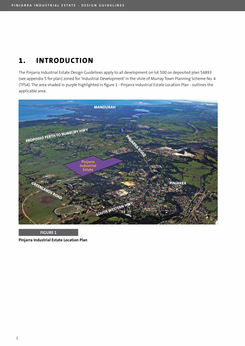
1. INTRODUCTION
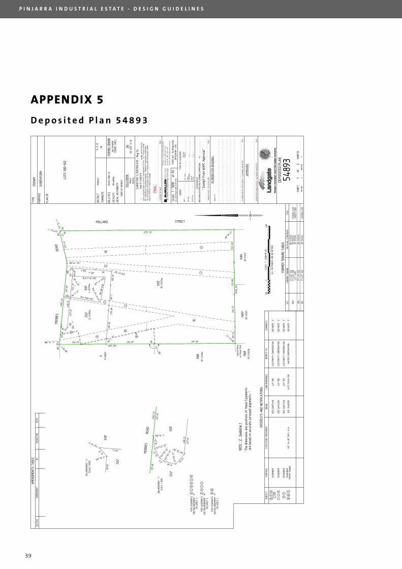
The Pinjarra Industrial Estate Design Guidelines apply to all development on lot 500 on deposited plan 54893
(see appendix 5 for plan) zoned for ‘Industrial Development’ in the shire of Murray Town Planning Scheme No. 4
(TPS4). The area shaded in purple highlighted in figure 1 - Pinjarra Industrial Estate location Plan - outlines the
applicable area.
MANDURAH
PINJARRA ROAD
PINJARRA
SOUTH WESTERN HWY
GREENLANDS ROAD
PROPOSED PERTH TO BUNBURY HWY
PinjarraIndustrial
Estate
FIGURE 1
Pinjarra Industrial Estate Location Plan
P I N J A R R A I N D U S T R I A L E S T A T E - D E S I G N G U I D E L I N E S
2
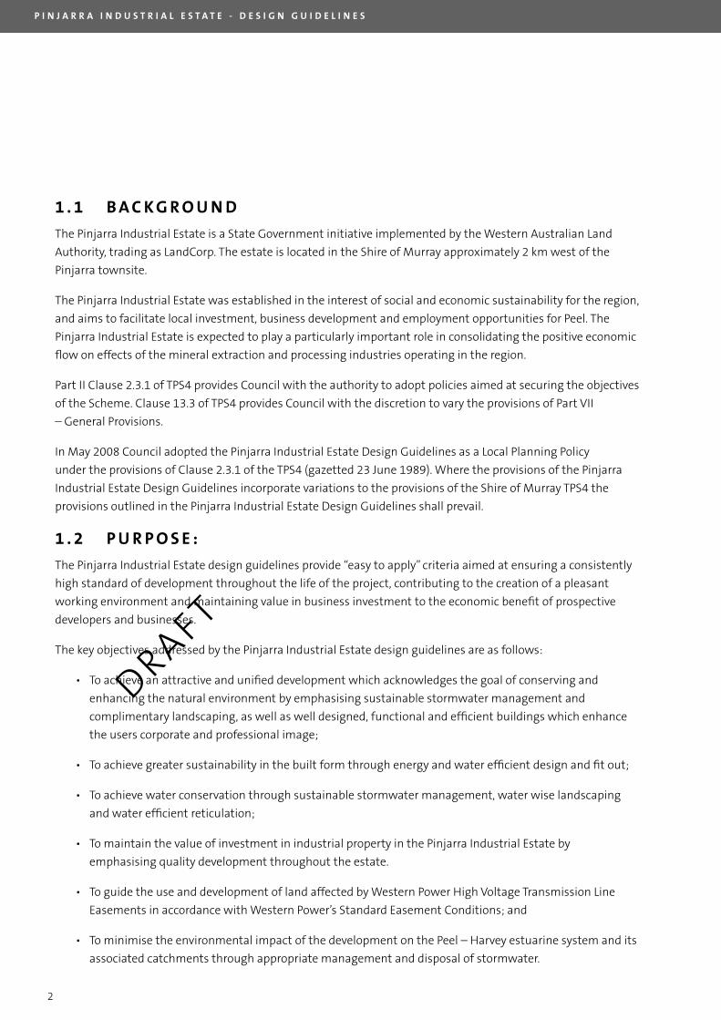
1 . 1 B A C K G R O U N D
The Pinjarra Industrial Estate is a State Government initiative implemented by the Western Australian land
Authority, trading as landCorp. The estate is located in the Shire of Murray approximately 2 km west of the
Pinjarra townsite.
The Pinjarra Industrial Estate was established in the interest of social and economic sustainability for the region,
and aims to facilitate local investment, business development and employment opportunities for Peel. The
Pinjarra Industrial Estate is expected to play a particularly important role in consolidating the positive economic
flow on effects of the mineral extraction and processing industries operating in the region.
Part II Clause 2.3.1 of TPS4 provides Council with the authority to adopt policies aimed at securing the objectives
of the Scheme. Clause 13.3 of TPS4 provides Council with the discretion to vary the provisions of Part VII
– General Provisions.
In May 2008 Council adopted the Pinjarra Industrial Estate Design Guidelines as a local Planning Policy
under the provisions of Clause 2.3.1 of the TPS4 (gazetted 23 June 1989). Where the provisions of the Pinjarra
Industrial Estate Design Guidelines incorporate variations to the provisions of the Shire of Murray TPS4 the
provisions outlined in the Pinjarra Industrial Estate Design Guidelines shall prevail.
1 . 2 P U R P O S E :
The Pinjarra Industrial Estate design guidelines provide “easy to apply” criteria aimed at ensuring a consistently
high standard of development throughout the life of the project, contributing to the creation of a pleasant
working environment and maintaining value in business investment to the economic benefit of prospective
developers and businesses.
The key objectives addressed by the Pinjarra Industrial Estate design guidelines are as follows:
• To achieve an attractive and unified development which acknowledges the goal of conserving and
enhancing the natural environment by emphasising sustainable stormwater management and
complimentary landscaping, as well as well designed, functional and efficient buildings which enhance
the users corporate and professional image;
• To achieve greater sustainability in the built form through energy and water efficient design and fit out;
• To achieve water conservation through sustainable stormwater management, water wise landscaping
and water efficient reticulation;
• To maintain the value of investment in industrial property in the Pinjarra Industrial Estate by
emphasising quality development throughout the estate.
• To guide the use and development of land affected by Western Power High Voltage Transmission line
Easements in accordance with Western Power’s Standard Easement Conditions; and
• To minimise the environmental impact of the development on the Peel – Harvey estuarine system and its
associated catchments through appropriate management and disposal of stormwater.
DRAFT
P I N J A R R A I N D U S T R I A L E S T A T E - D E S I G N G U I D E L I N E S
3
2. DEvELOPMENT APPROvAL PROCESS
All development proposals in the Pinjarra Industrial Estate require endorsement from both landCorp and the
Shire of Murray before construction can commence.
The endorsement will be a two stage process:
Stage 1 involves the approval of the development proposal in general terms by both landCorp and the Shire of
Murray, resulting in an Approval to Commence Development issued by the Shire.
Stage 2 involves the approval by both landCorp and the Shire of Murray of the detailed building documentation,
resulting in the issue of a Building licence from the Shire.
The complete approval process is detailed below:
1. Prior to the submission of development proposals, purchasers and/or their design consultants are
required to meet with landCorp’s ‘Estate Architect’ to clarify the intent of the design guideline document.
landCorp ‘Estate Architect’ contact details:
Pinjarra Industrial Estate
Hodge & Collard Architects
level 3, 38 Richardson Street
Ph: 08 9322 5144
West Perth WA 6005
2. Submission of development proposal to the ‘Estate Architect’
3. landCorp’s ‘Estate Architect’ will assess each development proposal in accordance with the design
guidelines. Section 2.1 outlines in detail submission requirements for the first stage of approval. Upon
satisfactory performance under the design guidelines the ‘Estate Architect’ and the Shire of Murray will
endorse the plans as compliant and advise landCorp accordingly. landCorp will forward an approval
letter and copies of the stamped plans to the proponent and Shire of Murray for planning approval.
4. Submission of the landCorp endorsed development proposal to the Shire of Murray for an Application to
Commence Development.
5. Receipt of Shire of Murray planning approval.
6. Submission of detailed building documentation together with a copy of the Shire planning approval
(including conditions) to landCorp’s ‘Estate Architect’ for endorsement. Section 2.2 outlines submission
requirements for the second stage of assessment. The inclusion of a second level of assessment allows
landCorp and the Shire of Murray to enforce built form and building fit out sustainability initiatives
proposed by the proponent.
P I N J A R R A I N D U S T R I A L E S T A T E - D E S I G N G U I D E L I N E S
4
7. Following landCorp’s and the Shire of Murray’s endorsement an approval letter and approved plans will
be sent to the proponent and Shire of Murray for building licence assessment.
8. Submission of the endorsed building documentation to the Shire of Murray for an application for a
building licence.
9. Following receipt of the Shire of Murray building licence the proponent is permitted the commencement
of development on site.
10. Upon practical completion landCorp’s ‘Estate Architect’ and other representatives will conduct a
building inspection of the site and premises, to determine whether the completed development is in
accordance with the approved building documentation.
11. Upon approval from landCorp the caveat on the title can be removed.
To ensure efficiency in the design guideline assessment and approval process all development proposals should
be forwarded directly to the ‘Estate Architect’ in electronic pdf format.
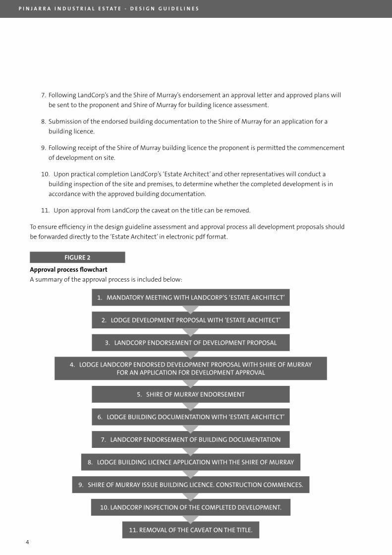
Approval process flowchart
A summary of the approval process is included below:
FIGURE 2
1. Mandatory Meeting with LandCorp’s ‘estate arChiteCt’
2. Lodge deveLopMent proposaL with ‘estate arChiteCt’
3. LandCorp endorseMent of deveLopMent proposaL
4. Lodge LandCorp endorsed deveLopMent proposaL with shire of Murray for an appLiCation for deveLopMent approvaL
5. shire of Murray endorseMent
6. Lodge buiLding doCuMentation with ‘estate arChiteCt’
7. LandCorp endorseMent of buiLding doCuMentation
8. Lodge buiLding LiCenCe appLiCation with the shire of Murray
9. shire of Murray issue buiLding LiCenCe. ConstruCtion CoMMenCes.
10. LandCorp inspeCtion of the CoMpLeted deveLopMent.
11. reMovaL of the Caveat on the titLe.
P I N J A R R A I N D U S T R I A L E S T A T E - D E S I G N G U I D E L I N E S
5
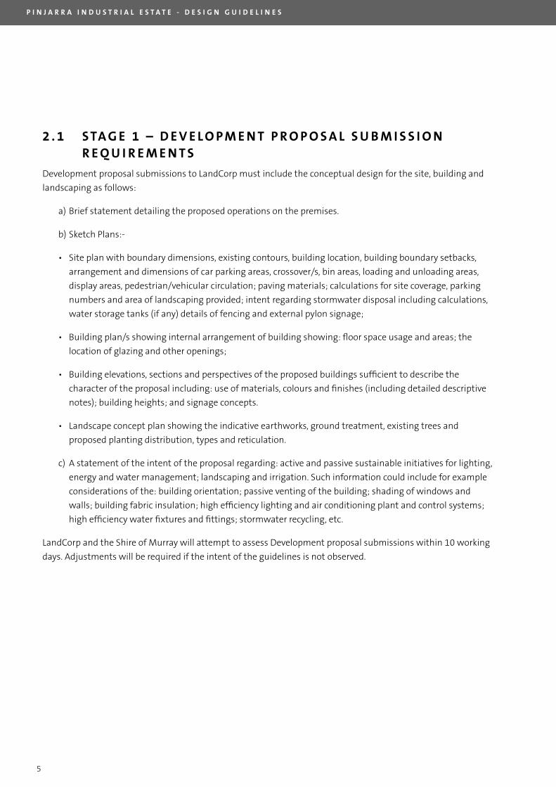
2 . 1 S TA G E 1 – D E V E L O P M E N T P R O P O S A L S U B M I S S I O N R E q U I R E M E N T S
Development proposal submissions to landCorp must include the conceptual design for the site, building and
landscaping as follows:
a) Brief statement detailing the proposed operations on the premises.
b) Sketch Plans:-
• Site plan with boundary dimensions, existing contours, building location, building boundary setbacks,
arrangement and dimensions of car parking areas, crossover/s, bin areas, loading and unloading areas,
display areas, pedestrian/vehicular circulation; paving materials; calculations for site coverage, parking
numbers and area of landscaping provided; intent regarding stormwater disposal including calculations,
water storage tanks (if any) details of fencing and external pylon signage;
• Building plan/s showing internal arrangement of building showing: floor space usage and areas; the
location of glazing and other openings;
• Building elevations, sections and perspectives of the proposed buildings sufficient to describe the
character of the proposal including: use of materials, colours and finishes (including detailed descriptive
notes); building heights; and signage concepts.
• landscape concept plan showing the indicative earthworks, ground treatment, existing trees and
proposed planting distribution, types and reticulation.
c) A statement of the intent of the proposal regarding: active and passive sustainable initiatives for lighting,
energy and water management; landscaping and irrigation. Such information could include for example
considerations of the: building orientation; passive venting of the building; shading of windows and
walls; building fabric insulation; high efficiency lighting and air conditioning plant and control systems;
high efficiency water fixtures and fittings; stormwater recycling, etc.
landCorp and the Shire of Murray will attempt to assess Development proposal submissions within 10 working
days. Adjustments will be required if the intent of the guidelines is not observed.
P I N J A R R A I N D U S T R I A L E S T A T E - D E S I G N G U I D E L I N E S
6
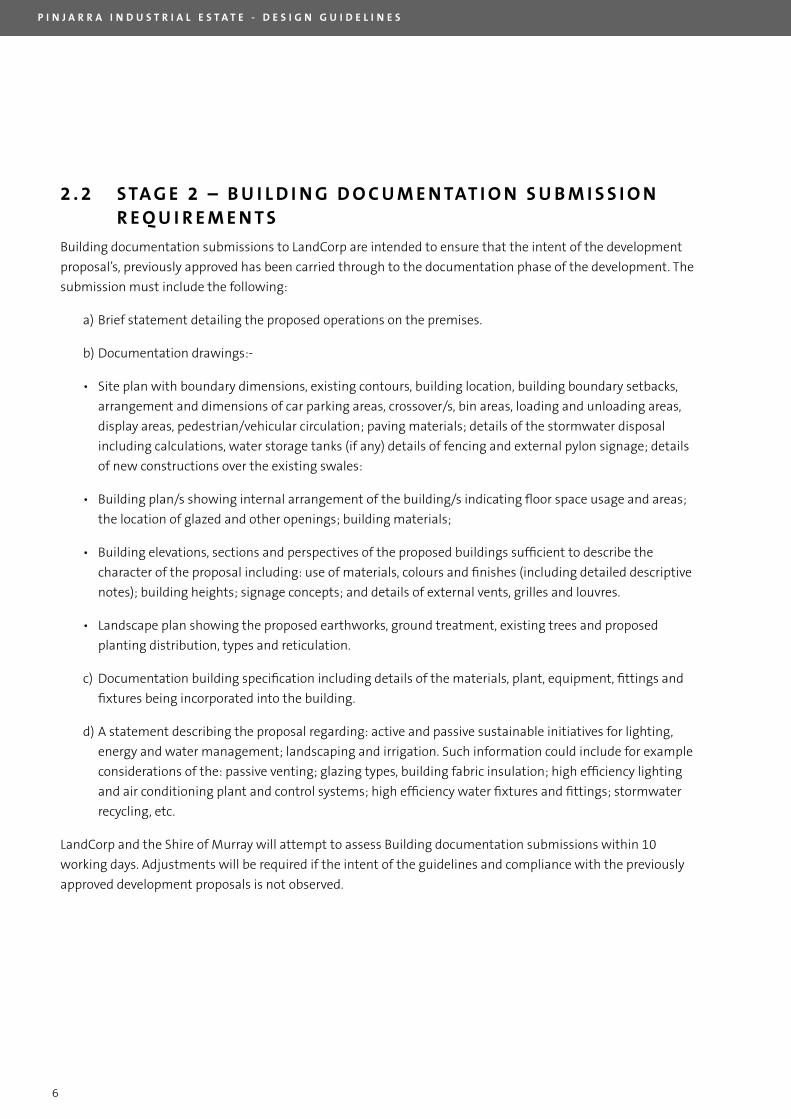
2 . 2 S TA G E 2 – B U I L D I N G D O C U M E N TAT I O N S U B M I S S I O N R E q U I R E M E N T S
Building documentation submissions to landCorp are intended to ensure that the intent of the development
proposal’s, previously approved has been carried through to the documentation phase of the development. The
submission must include the following:
a) Brief statement detailing the proposed operations on the premises.
b) Documentation drawings:-
• Site plan with boundary dimensions, existing contours, building location, building boundary setbacks,
arrangement and dimensions of car parking areas, crossover/s, bin areas, loading and unloading areas,
display areas, pedestrian/vehicular circulation; paving materials; details of the stormwater disposal
including calculations, water storage tanks (if any) details of fencing and external pylon signage; details
of new constructions over the existing swales:
• Building plan/s showing internal arrangement of the building/s indicating floor space usage and areas;
the location of glazed and other openings; building materials;
• Building elevations, sections and perspectives of the proposed buildings sufficient to describe the
character of the proposal including: use of materials, colours and finishes (including detailed descriptive
notes); building heights; signage concepts; and details of external vents, grilles and louvres.
• landscape plan showing the proposed earthworks, ground treatment, existing trees and proposed
planting distribution, types and reticulation.
c) Documentation building specification including details of the materials, plant, equipment, fittings and
fixtures being incorporated into the building.
d) A statement describing the proposal regarding: active and passive sustainable initiatives for lighting,
energy and water management; landscaping and irrigation. Such information could include for example
considerations of the: passive venting; glazing types, building fabric insulation; high efficiency lighting
and air conditioning plant and control systems; high efficiency water fixtures and fittings; stormwater
recycling, etc.
landCorp and the Shire of Murray will attempt to assess Building documentation submissions within 10
working days. Adjustments will be required if the intent of the guidelines and compliance with the previously
approved development proposals is not observed.
P I N J A R R A I N D U S T R I A L E S T A T E - D E S I G N G U I D E L I N E S
7
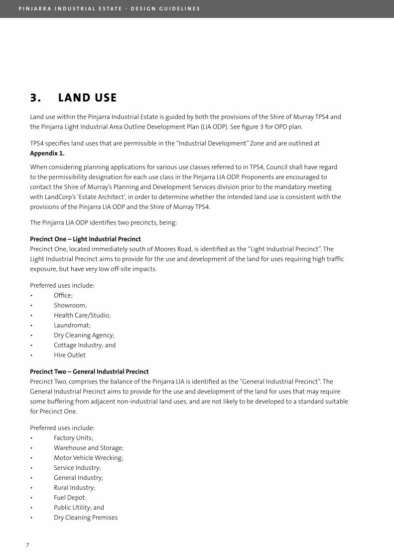
3. LAND USE
land use within the Pinjarra Industrial Estate is guided by both the provisions of the Shire of Murray TPS4 and
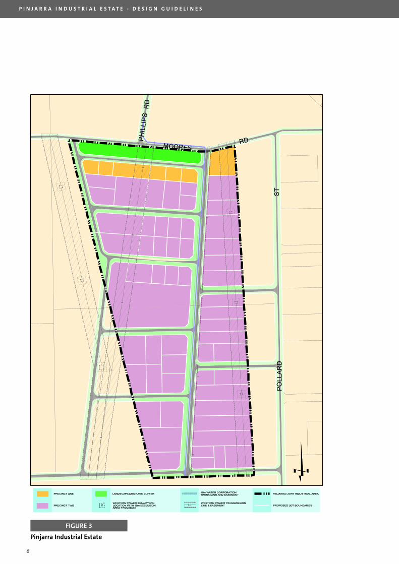
the Pinjarra light Industrial Area Outline Development Plan (lIA ODP). See figure 3 for OPD plan.
TPS4 specifies land uses that are permissible in the “Industrial Development” Zone and are outlined at
Appendix 1.
The Pinjarra lIA ODP identifies two precincts, being:
Precinct One – Light Industrial Precinct
Precinct One, located immediately south of Moores Road, is identified as the “light Industrial Precinct”. The
light Industrial Precinct aims to provide for the use and development of the land for uses requiring high traffic
exposure, but have very low off-site impacts.
Preferred uses include:
• Office;
• Showroom;
• Health Care/Studio;
• laundromat;
• Dry Cleaning Agency;
• Cottage Industry; and
• Hire Outlet
Precinct Two – General Industrial Precinct
Precinct Two, comprises the balance of the Pinjarra lIA is identified as the “General Industrial Precinct”. The
General Industrial Precinct aims to provide for the use and development of the land for uses that may require
some buffering from adjacent non-industrial land uses, and are not likely to be developed to a standard suitable
for Precinct One.
Preferred uses include:
• Factory Units;
• Warehouse and Storage;
• Motor Vehicle Wrecking;
• Service Industry;
• General Industry;
• Rural Industry;
• Fuel Depot:
• Public Utility; and
• Dry Cleaning Premises
When considering planning applications for various use classes referred to in TPS4, Council shall have regard
to the permissibility designation for each use class in the Pinjarra lIA ODP. Proponents are encouraged to
contact the Shire of Murray’s Planning and Development Services division prior to the mandatory meeting
with landCorp’s ‘Estate Architect’, in order to determine whether the intended land use is consistent with the
provisions of the Pinjarra lIA ODP and the Shire of Murray TPS4.
P I N J A R R A I N D U S T R I A L E S T A T E - D E S I G N G U I D E L I N E S
8
Pinjarra Industrial Estate
FIGURE 3
P I N J A R R A I N D U S T R I A L E S T A T E - D E S I G N G U I D E L I N E S
9
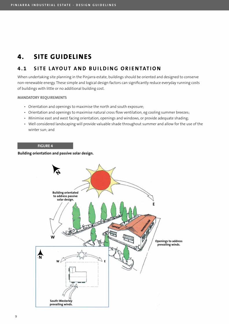
4. SITE GUIDELINES
4 . 1 S I T E L AYO U T A N D B U I L D I N G O R I E N TAT I O N
When undertaking site planning in the Pinjarra estate, buildings should be oriented and designed to conserve
non-renewable energy. These simple and logical design factors can significantly reduce everyday running costs
of buildings with little or no additional building cost.
MANDATORY REqUIREMENTS
• Orientation and openings to maximise the north and south exposure;
• Orientation and openings to maximise natural cross flow ventilation, eg cooling summer breezes;
• Minimise east and west facing orientation, openings and windows, or provide adequate shading;
• Well considered landscaping will provide valuable shade throughout summer and allow for the use of the
winter sun; and
FIGURE 4
Building orientatedto address passive
solar design.
Openings to addressprevailing winds.
N
S
E
W
N
S
EW
South-Westerleyprevailing winds.
W
W
E
E
Building orientation and passive solar design.
P I N J A R R A I N D U S T R I A L E S T A T E - D E S I G N G U I D E L I N E S
10
4 . 2 S I T E C O V E R A G E
MANDATORY REqUIREMENT
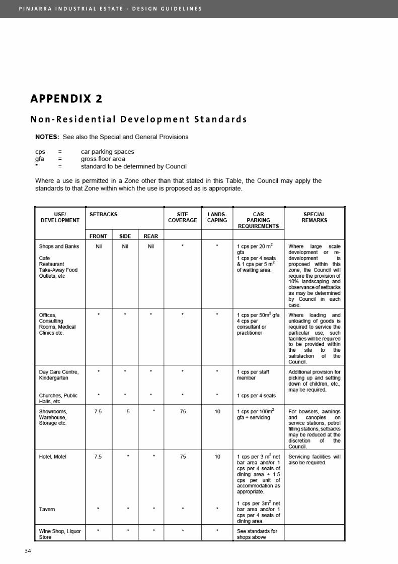
Maximum site coverage shall be in accordance with the provisions of Table II – Non Residential Development
Standards of TPS4 in consideration of setbacks, landscaping, parking and the Building Code of Australia
requirements as outlined in Appendix 2. Where setback, parking and landscaping requirements outlined in this
document differ from those outlined in Table II - Non Residential Development Standards of TPS4, the provisions
of the Pinjarra Industrial Estate design guidelines shall prevail.
All development in the Pinjarra Industrial Estate must achieve a minimum site coverage of 20% of the
unencumbered lot area. Western Power Easements encumber certain lots throughout the estate.
4 . 3 B U I L D I N G L AYO U T A N D S E T B A C K
MANDATORY REqUIREMENT
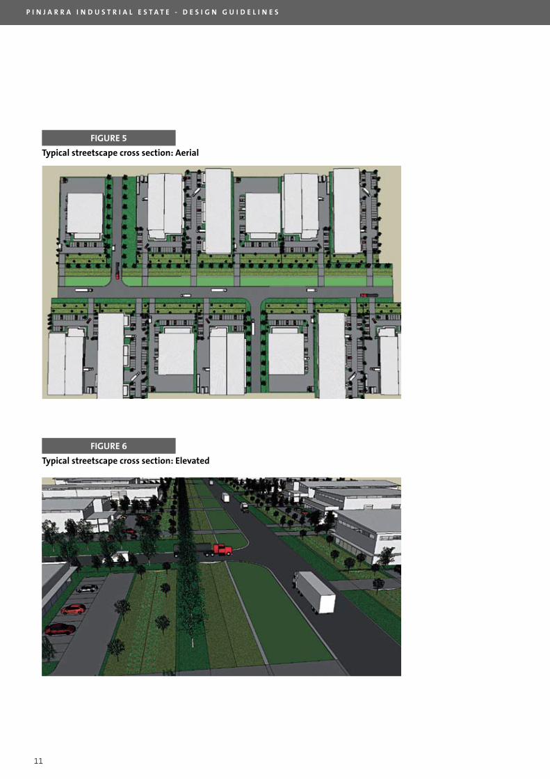
All development, including all buildings and structures, car parking and hardstand areas must be setback a
minimum of 11 metres from the lot boundary on primary street frontages and 5 metres from the lot boundary
on secondary street frontages. The determination between primary and secondary frontages is at the discretion
of landCorp and the Shire of Murray. Figures 5 & 6 provide a typical road cross section of any given street within
the Pinjarra Industrial Estate. Figures 7 & 8 outline the variety in site layout and building setback options for
the estate.
The maximum building setback from the primary street frontage is 25 metres.
Side and rear setbacks outlined in Table II - Non Residential Development Standards of TPS4 Appendix 2 do not
apply within the Pinjarra Industrial Estate and may be reduced to nil, subject to landCorp approval, and Shire of
Murray planning, engineering and building approval.
Developers are encouraged to setback buildings a minimum of 3 metres from both the side and rear lot
boundaries to assist with natural light penetration and natural cross flow ventilation. Developments featuring
a nil side and rear setback will be required to demonstrate ventilation and natural lighting capability in
accordance with landCorp’s development standards. See section 5.4 for guidance on natural light and
ventilation.
4 . 4 G E O T E C H N I C A L S TA N D A R D S
All lots in the Pinjarra Industrial Estate have been prepared with a minimum of 1 metre of clean fill over
the natural sandy/clay soils. The preparation provides for an ‘S’ classification under AS 2870 (1996).
lots have generally been finished with a grade towards the surrounding roads. Therefore as level slabs are
expected to be constructed some earthworks on site will be necessary.
Purchasers will need to undertake their own geotechnical and structural investigations when
constructing buildings on site if any proposed earthworks comprise the 1 metre depth of fill above the
natural sandy/clay soils or where the structural loads are outside that allowed for in AS2870.
P I N J A R R A I N D U S T R I A L E S T A T E - D E S I G N G U I D E L I N E S
11
FIGURE 5
FIGURE 6
Typical streetscape cross section: Aerial
Typical streetscape cross section: Elevated
P I N J A R R A I N D U S T R I A L E S T A T E - D E S I G N G U I D E L I N E S
12
4 . 5 V E H I C L E A C C E S S A N D PA R K I N G
MANDATORY REqUIREMENT
The provision of car parking bays shall be in accordance with the provisions of Table II – Non Residential
Development Standards of TPS4 Appendix 2. Figures 7 & 8 outline a variety of site and car parking layout
options for the estate.
All car parking and vehicle access must be contained on site.
Roadways and parking areas within a development must be planned to achieve the following:
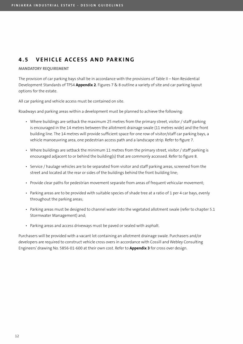
• Where buildings are setback the maximum 25 metres from the primary street, visitor / staff parking
is encouraged in the 14 metres between the allotment drainage swale (11 metres wide) and the front
building line. The 14 metres will provide sufficient space for one row of visitor/staff car parking bays, a
vehicle manoeuvring area, one pedestrian access path and a landscape strip. Refer to figure 7.
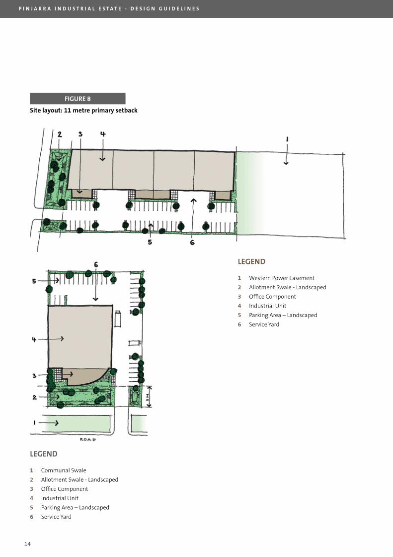
• Where buildings are setback the minimum 11 metres from the primary street, visitor / staff parking is
encouraged adjacent to or behind the building(s) that are commonly accessed. Refer to figure 8.
• Service / haulage vehicles are to be separated from visitor and staff parking areas, screened from the
street and located at the rear or sides of the buildings behind the front building line;
• Provide clear paths for pedestrian movement separate from areas of frequent vehicular movement;
• Parking areas are to be provided with suitable species of shade tree at a ratio of 1 per 4 car bays, evenly
throughout the parking areas;
• Parking areas must be designed to channel water into the vegetated allotment swale (refer to chapter 5.1
Stormwater Management) and;
• Parking areas and access driveways must be paved or sealed with asphalt.
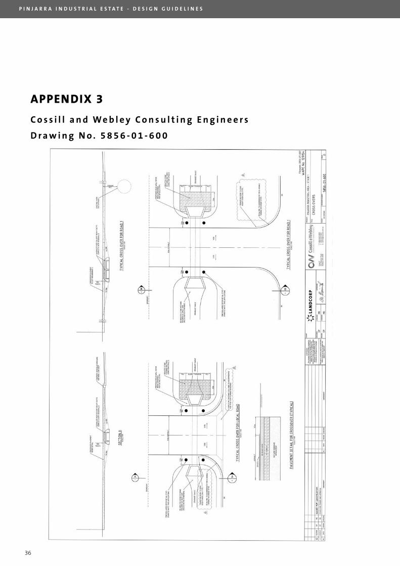
Purchasers will be provided with a vacant lot containing an allotment drainage swale. Purchasers and/or
developers are required to construct vehicle cross overs in accordance with Cossill and Webley Consulting
Engineers’ drawing No. 5856-01-600 at their own cost. Refer to Appendix 3 for cross over design.
P I N J A R R A I N D U S T R I A L E S T A T E - D E S I G N G U I D E L I N E S
13
FIGURE 7
LEGEND
1 Western Power Easement
2 Allotment Swale - landscaped
3 Office Component
4 Industrial Unit
5 Parking Area – landscaped
6 Service Yard
Site layout: 25 metre primary setback
P I N J A R R A I N D U S T R I A L E S T A T E - D E S I G N G U I D E L I N E S
14
FIGURE 8
Site layout: 11 metre primary setback
LEGEND
1 Communal Swale
2 Allotment Swale - landscaped
3 Office Component
4 Industrial Unit
5 Parking Area – landscaped
6 Service Yard
LEGEND
1 Western Power Easement
2 Allotment Swale - landscaped
3 Office Component
4 Industrial Unit
5 Parking Area – landscaped
6 Service Yard
P I N J A R R A I N D U S T R I A L E S T A T E - D E S I G N G U I D E L I N E S
15
4 . 6 E X T E R N A L S E R V I C E A N D S T O R A G E A R E A S
MANDATORY REqUIREMENT
External service and storage areas shall be designed to comply with Clause 7.4 of TPS4 as follows:
• No open storage of goods, unserviceable vehicles or machinery shall be carried out on within the front
boundary setback area (forward of the building line), which shall be used only for landscaping and
drainage, car parking, servicing, loading and unloading, or where appropriate and subject to the approval
of the Council, for trade display; and
• All open storage areas shall be screened from the street and adjoining properties by landscaping, fencing
and/or other means acceptable to landCorp and the Shire of Murray.
• Rubbish bin storage areas must also be screened from all road frontage. The dimensions and location of
rubbish bin storage areas will be at the discretion of landCorp and the Shire of Murray.
• All plant and equipment storage areas are to be adequately screened from public view from both road
frontages.
4 . 7 B O U N D A R Y F E N C I N G
The intent of boundary fencing in the Pinjarra Industrial Estate is to provide security for businesses without
compromising the visual aesthetics and overall character of the development. landCorp’s ‘Estate Architect’
should be contacted to provide advice on different site layouts and fencing options.
MANDATORY REqUIREMENT
• Where a building is setback the maximum 25 metres from the front lot boundary no fencing is permitted
forward of the building line.
• Where a building is setback the minimum 11 metres from the front lot boundary, or 5 metres from the
secondary street boundary, no fencing will be permitted forward of the 25 metre maximum building
setback line. landCorp and the Shire of Murray may choose to exercise discretion in reducing the front
and/or side fencing setback requirement where site security is considered a risk.
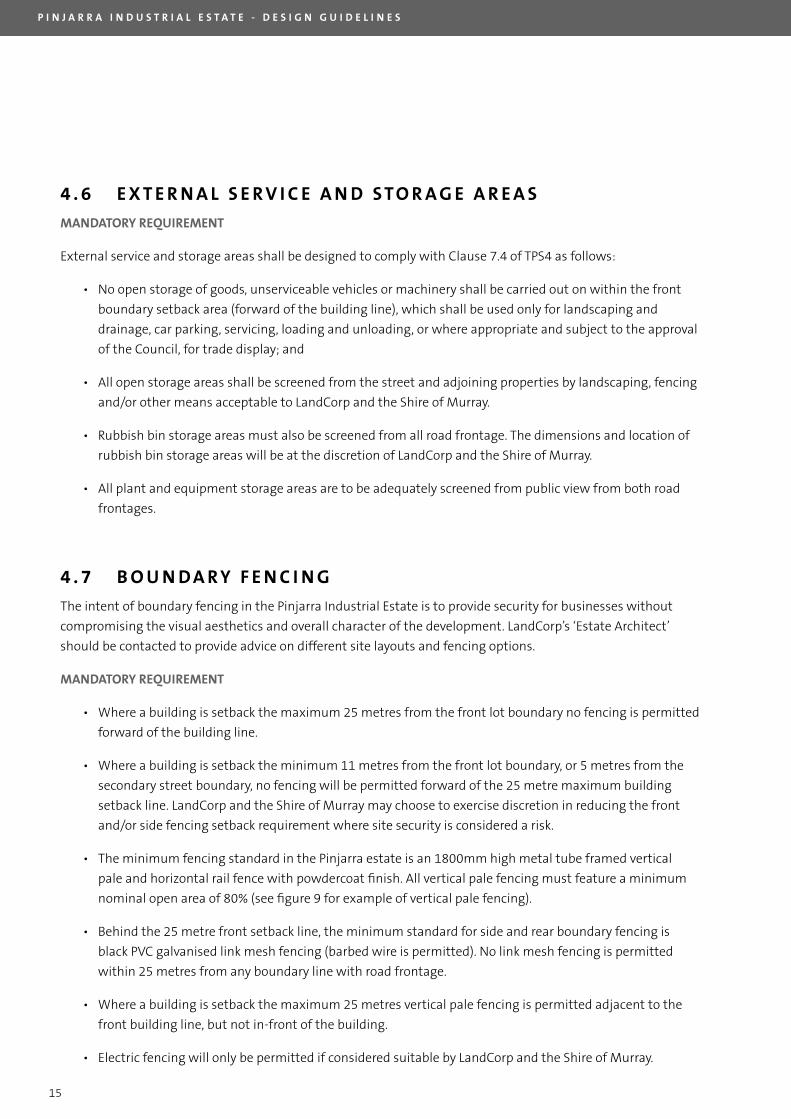
• The minimum fencing standard in the Pinjarra estate is an 1800mm high metal tube framed vertical
pale and horizontal rail fence with powdercoat finish. All vertical pale fencing must feature a minimum
nominal open area of 80% (see figure 9 for example of vertical pale fencing).
• Behind the 25 metre front setback line, the minimum standard for side and rear boundary fencing is
black PVC galvanised link mesh fencing (barbed wire is permitted). No link mesh fencing is permitted
within 25 metres from any boundary line with road frontage.
• Where a building is setback the maximum 25 metres vertical pale fencing is permitted adjacent to the
front building line, but not in-front of the building.
• Electric fencing will only be permitted if considered suitable by landCorp and the Shire of Murray.
P I N J A R R A I N D U S T R I A L E S T A T E - D E S I G N G U I D E L I N E S
16
Standard vertical pale fencing
FIGURE 9
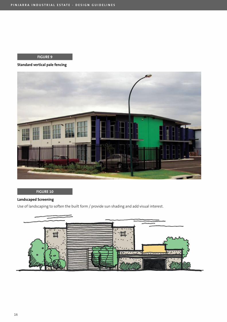
FIGURE 10
Landscaped Screening
Use of landscaping to soften the built form / provide sun shading and add visual interest.
P I N J A R R A I N D U S T R I A L E S T A T E - D E S I G N G U I D E L I N E S
17
5. NATURAL RESOURCE MANAGEMENT
5 . 1 S T O R M WAT E R M A N A G E M E N T
The Pinjarra Industrial Estate is located in the catchments of the Peel Inlet and Harvey Estuary. The estate is
positioned in close proximity to wetland systems in the Murray groundwater area. Natural terrain in the estate
consists predominantly of heavy clays which restrict the rate of natural infiltration of stormwater on site.
In recognition of Pinjarra’s environmental sensitivities landCorp has taken a unique approach to stormwater
management. The estate features a series of private property allotment swales and roadside drainage
swales, which collect and convey stormwater overflow from individual lots and road reserves to a vegetated
compensation basin at the northern end of the site abutting Moores Road. All drainage swales in the Pinjarra
Industrial Estate will be vegetated to the satisfaction of landCorp and the Shire of Murray.
The Pinjarra Urban Water Balance Management Plan was endorsed by the Department of Water in April 2007,
and is recognised by the department as demonstrating best practice in water sensitive urban design for an
industrial estate.
MANDATORY REqUIREMENT
Stormwater management shall meet the following criteria:
i. Each property is required to retain stormwater runoff equivalent to a 1 year ARI, 1 hour duration rainfall
event or 17 mm of rainfall, using a minimum coefficient of runoff of 0.85 over the allotment area,
excluding Western Power transmission easements where these do not contribute to the catchment.
Example – Stormwater runoff required to be retained for 3,600 m2 site where 600 m2 is taken by
Western Power easement + (3,600 – 600) x 0.85 x 0.017 = 43.4 m3;
ii. Stormwater runoff can be directed towards the allotment swale (wherein the subdivider has provided a
nominally sized retention swale) and/or to soakwells and
iii. Depending on the usage of the lot: if the local authority deems it as creating high level of pollutants
(chemical and hazardous materials), a lined retention basin to capture any runoff from the designated
polluted area (to be treated or removed from the site), will be required.
NOTES:
1. Each property owner shall provide calculations to show the required stormwater retention capacity has
been achieved for the proposed site development. Stormwater calculations must be submitted with
building and landscaping plans to landCorp and the Shire of Murray for approval.
2. The on-site drainage design should reflect the requirements of the approved GHD Urban Water Balance
Plan, for the subdivision dated February 2007. A copy of the report is available on the landCorp website
www.landcorp.com.au (Go to project finder and select Pinjarra).
P I N J A R R A I N D U S T R I A L E S T A T E - D E S I G N G U I D E L I N E S
18
5 . 2 L A N D S C A P I N G
MANDATORY REqUIREMENT
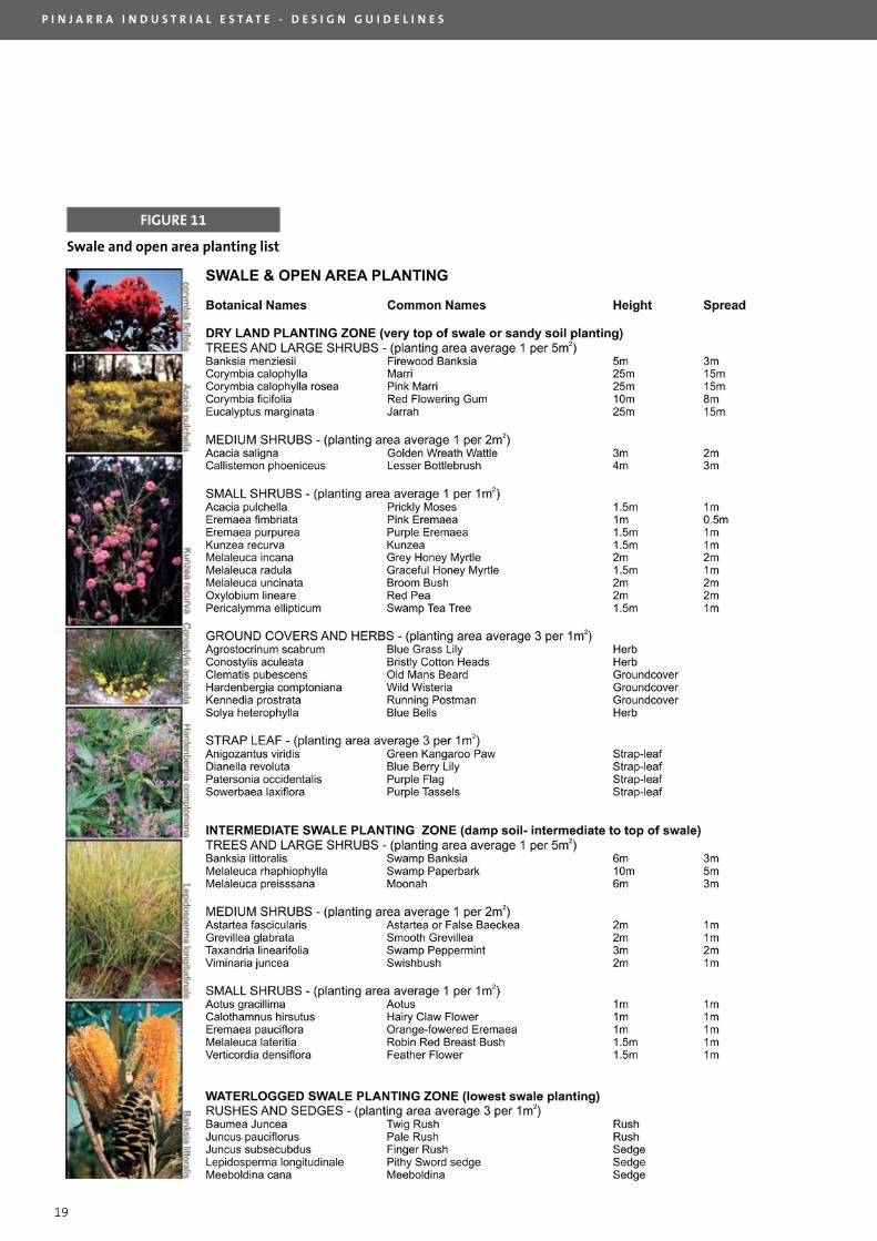
• All plant species must be selected and planted in accordance with the swale and open area planting list
(figure 11).
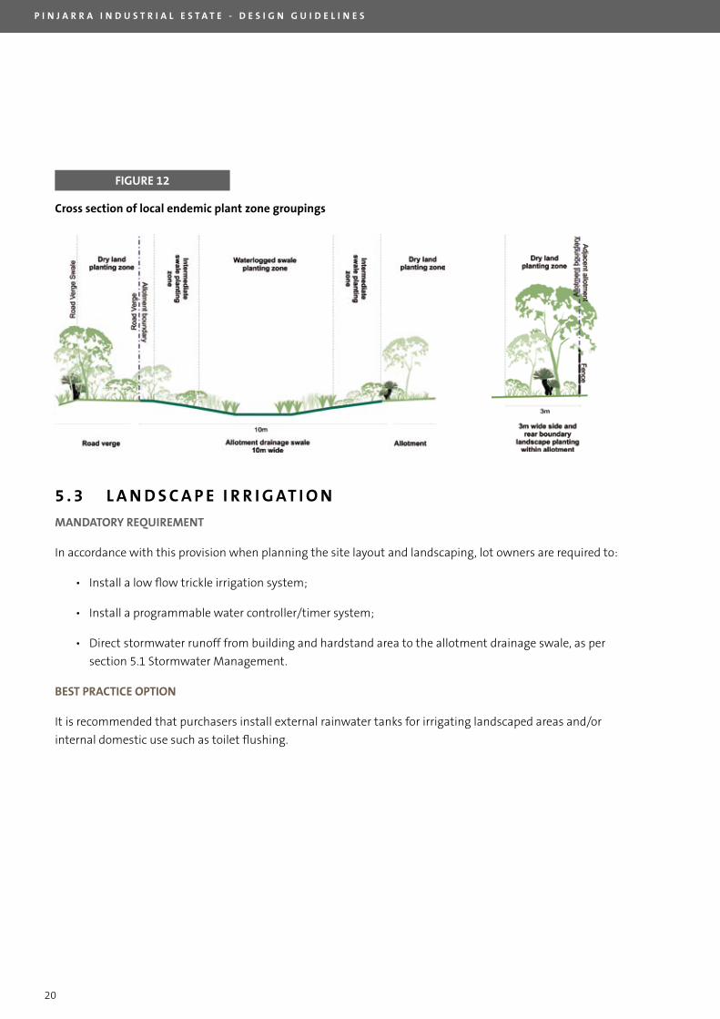
• All approved plant species must be planted in the appropriate planting zones as outlined in figure 12. For
example: waterlogged swale planting, intermediate swale planting, intermediate swale planting, and dry
planting.
• The purchaser is required to vegetate and maintain the full extent of the 10 metre wide allotment
drainage swale, which spans across the front section of the lot, to the satisfaction of landCorp and the
Shire of Murray.
• landscaped areas on all lots are to comprise a minimum of 10 metres in depth from primary street
frontages, and 5 metres in depth from the secondary street frontage where applicable.
• A minimum one metre wide landscape strip, utilising small shrubs, ground covers and herbs, and/or strap
leaf from the dry planting zone plant list (figure 11) is required at the base of any building line with road
frontage.
• Where a development incorporates a visitor car parking area between the allotment swale and front building
line, a pedestrian access path of 1.5 metres in width is to be constructed between the visitor car park area
and building landscape area. The pedestrian access path must be constructed to Australian Standards
1428.1-2001: Design for access and mobility – General requirements for access – New building work.
• Where the front building line is positioned within the 11 to 25 metre setback range from the primary lot
boundary, a minimum one metre wide landscaping strip is required along each of the side lot boundaries
between the primary lot boundary and the front building line;
• All landscape and planting shall be undertaken by a qualified contractor.
P I N J A R R A I N D U S T R I A L E S T A T E - D E S I G N G U I D E L I N E S
19
FIGURE 11
Swale and open area planting list
P I N J A R R A I N D U S T R I A L E S T A T E - D E S I G N G U I D E L I N E S
20
5 . 3 L A N D S C A P E I R R I G AT I O N
MANDATORY REqUIREMENT
In accordance with this provision when planning the site layout and landscaping, lot owners are required to:
• Install a low flow trickle irrigation system;
• Install a programmable water controller/timer system;
• Direct stormwater runoff from building and hardstand area to the allotment drainage swale, as per
section 5.1 Stormwater Management.
BEST PRACTICE OPTION
It is recommended that purchasers install external rainwater tanks for irrigating landscaped areas and/or
internal domestic use such as toilet flushing.
FIGURE 12
Cross section of local endemic plant zone groupings
P I N J A R R A I N D U S T R I A L E S T A T E - D E S I G N G U I D E L I N E S
21
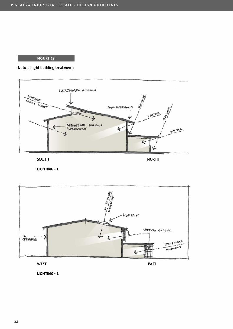
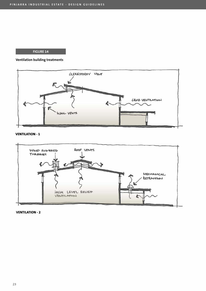
5 . 4 N AT U R A L L I G H T A N D V E N T I L AT I O N
Further to the passive site layout and building orientation guidelines outlined in section 4.1 the following
building design initiatives will aid the conservation of non-renewable energy and improve employee comfort by
assisting the penetration of natural light and ventilation. Figures 13 & 14 illustrate natural light and ventilation
building treatment options.
Section 4.3: Building Layout and Setback, encourages developers to incorporate a minimum side boundary
setback of 3 metres. This approach allows buildings to feature openings on both side walls therefore assisting
natural light penetration and cross flow ventilation. However, in the interest of maximising the developable
area of industrial land in the estate, landCorp and the Shire of Murray are prepared to consider alternative
design solutions to assist with natural light penetration and ventilation so that buildings can be constructed
with a nil side and rear setback.
The following building treatments are optional initiatives designed to assist natural light penetration and
building ventilation. Developers will not be bound to, nor should be limited to, the following design treatments,
however where nil side and rear setbacks are proposed, building designers will need to demonstrate the
building’s ability to capture natural light and allow cross ventilation to the satisfaction of landCorp and the
Shire of Murray.
Natural light
• Rooflights
To introduce UV filtered sunlight into the centre of the building (consideration should be given to
minimising solar gain by careful selection of the translucent rooflight material).
• Clerestory windows
To introduce natural light, preferable diffuse southern light, into the centre of the building, thereby
reducing the requirement for artificial lighting.
Ventilation
• Side wall ventilation openings
To encourage cross-ventilation through the building
• Clerestory windows
To provide an outlet for warm air rising to a high level within the building and to promote cross
ventilation.
• Wind powered ventilation turbines
To aid the relief of hot air at high level and to encourage cooler air to enter at low level in the building,
thereby generating a ‘chimney stack effect’ for air circulation.
• Roof vents active or passive
large relief vents or cowl to further increase upward air flow in the building.
P I N J A R R A I N D U S T R I A L E S T A T E - D E S I G N G U I D E L I N E S
22
FIGURE 13
Natural light building treatments
SOUTH� NORTH
LIGHTING - 1
WEST� EAST
LIGHTING - 2
P I N J A R R A I N D U S T R I A L E S T A T E - D E S I G N G U I D E L I N E S
23
FIGURE 14
Ventilation building treatments
vENTILATION - 1
vENTILATION - 2
P I N J A R R A I N D U S T R I A L E S T A T E - D E S I G N G U I D E L I N E S
24
5 . 5 E X T E R N A L L I G H T I N G
MANDATORY REqUIREMENT
• High frequency compact fluorescent lamps or T5 Triphosphor fluorescent lamps are required for external
areas.
• lighting controlled by timer controls or motion sensors for all external lighting.
• No glare of light spill shall adversely impact adjoining properties or passing motorists.
5 . 6 I N T E R N A L L I G H T I N G
MANDATORY REqUIREMENT
As a minimum standard all developments in the Pinjarra Industrial Estate must feature, but shall not be limited to:
• light fittings that utilise high efficacy light sources such as high pressure sodium discharge lamps or T5
triphosphor fluorescent lights.
• Daylight / occupancy control systems. These control systems generally provide an average 5 year payback
through energy savings.
• lighting controlled by timer controls, photosensitive cells, or motion sensors to control operation of
specific light fixtures and fittings.
5 . 7 WAT E R C O N S E R VAT I O N
MANDATORY REqUIREMENT
The supply of potable water in Western Australia is a critical issue. The following options for building fit out are
consistent with the Building Code of Australia (BCA) Five Star Plus energy and water efficiency measures:
• solar or five-star gas (or heat pump) hot water systems;
• water efficient showerheads;
• water efficient tap fittings in all kitchen sinks and bathroom basins; and
• water efficient dual-flush toilets.
P I N J A R R A I N D U S T R I A L E S T A T E - D E S I G N G U I D E L I N E S
25
6. BUILT fORM
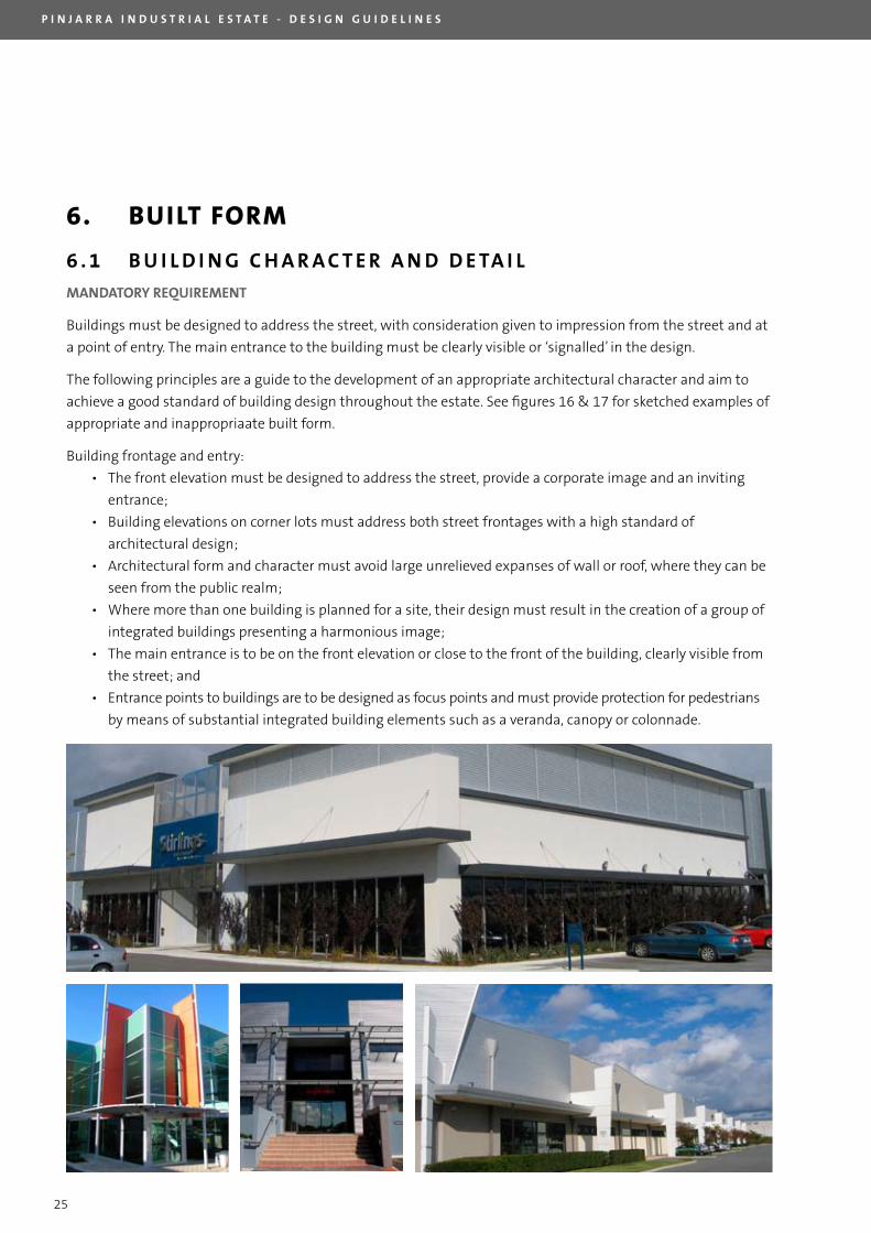
6 . 1 B U I L D I N G C H A R A C T E R A N D D E TA I L
MANDATORY REqUIREMENT
Buildings must be designed to address the street, with consideration given to impression from the street and at
a point of entry. The main entrance to the building must be clearly visible or ‘signalled’ in the design.
The following principles are a guide to the development of an appropriate architectural character and aim to
achieve a good standard of building design throughout the estate. See figures 16 & 17 for sketched examples of
appropriate and inappropriaate built form.
Building frontage and entry:
• The front elevation must be designed to address the street, provide a corporate image and an inviting
entrance;
• Building elevations on corner lots must address both street frontages with a high standard of
architectural design;
• Architectural form and character must avoid large unrelieved expanses of wall or roof, where they can be
seen from the public realm;
• Where more than one building is planned for a site, their design must result in the creation of a group of
integrated buildings presenting a harmonious image;
• The main entrance is to be on the front elevation or close to the front of the building, clearly visible from
the street; and
• Entrance points to buildings are to be designed as focus points and must provide protection for pedestrians
by means of substantial integrated building elements such as a veranda, canopy or colonnade.
P I N J A R R A I N D U S T R I A L E S T A T E - D E S I G N G U I D E L I N E S
26
6 . 2 M AT E R I A L S , F I N I S H E S A N D C O L O U R
MANDATORY REqUIREMENT
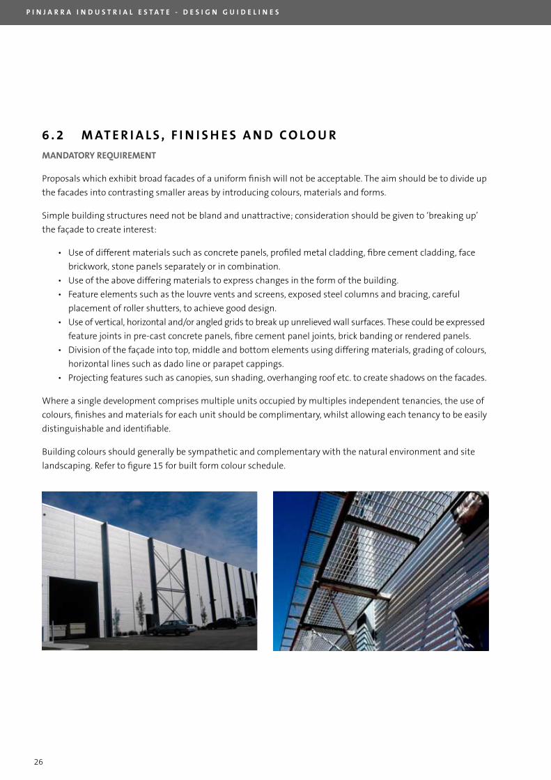
Proposals which exhibit broad facades of a uniform finish will not be acceptable. The aim should be to divide up
the facades into contrasting smaller areas by introducing colours, materials and forms.
Simple building structures need not be bland and unattractive; consideration should be given to ‘breaking up’
the façade to create interest:
• Use of different materials such as concrete panels, profiled metal cladding, fibre cement cladding, face
brickwork, stone panels separately or in combination.
• Use of the above differing materials to express changes in the form of the building.
• Feature elements such as the louvre vents and screens, exposed steel columns and bracing, careful
placement of roller shutters, to achieve good design.
• Use of vertical, horizontal and/or angled grids to break up unrelieved wall surfaces. These could be expressed
feature joints in pre-cast concrete panels, fibre cement panel joints, brick banding or rendered panels.
• Division of the façade into top, middle and bottom elements using differing materials, grading of colours,
horizontal lines such as dado line or parapet cappings.
• Projecting features such as canopies, sun shading, overhanging roof etc. to create shadows on the facades.
Where a single development comprises multiple units occupied by multiples independent tenancies, the use of
colours, finishes and materials for each unit should be complimentary, whilst allowing each tenancy to be easily
distinguishable and identifiable.
Building colours should generally be sympathetic and complementary with the natural environment and site
landscaping. Refer to figure 15 for built form colour schedule.
P I N J A R R A I N D U S T R I A L E S T A T E - D E S I G N G U I D E L I N E S
27
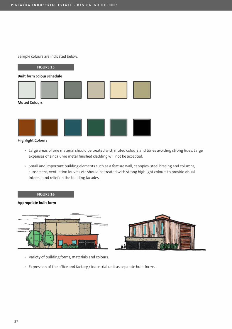
Sample colours are indicated below.
FIGURE 15
Built form colour schedule
Muted�Colours
Highlight�Colours
• large areas of one material should be treated with muted colours and tones avoiding strong hues. large
expanses of zincalume metal finished cladding will not be accepted.
• Small and important building elements such as a feature wall, canopies, steel bracing and columns,
sunscreens, ventilation louvres etc should be treated with strong highlight colours to provide visual
interest and relief on the building facades.
FIGURE 16
Appropriate built form
• Variety of building forms, materials and colours.
• Expression of the office and factory / industrial unit as separate built forms.
P I N J A R R A I N D U S T R I A L E S T A T E - D E S I G N G U I D E L I N E S
28
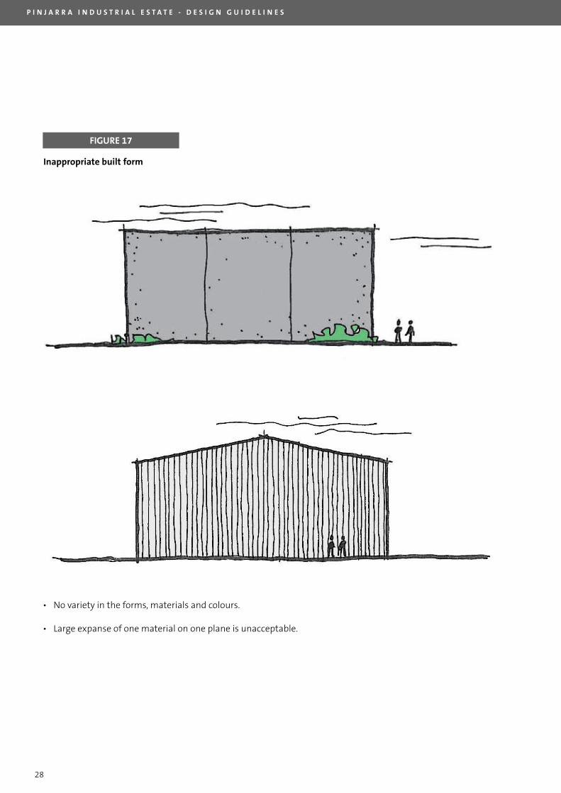
FIGURE 17
Inappropriate built form
• No variety in the forms, materials and colours.
• large expanse of one material on one plane is unacceptable.
P I N J A R R A I N D U S T R I A L E S T A T E - D E S I G N G U I D E L I N E S
29
6 . 3 P L A N T A N D E q U I P M E N T
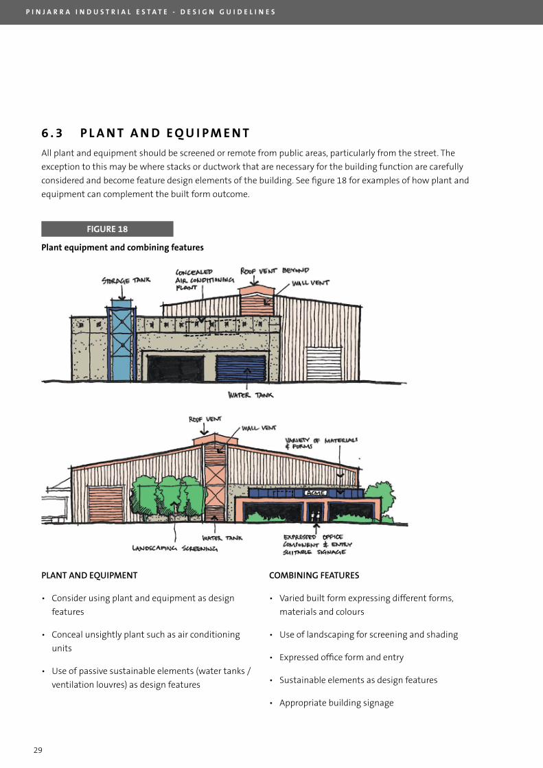
All plant and equipment should be screened or remote from public areas, particularly from the street. The
exception to this may be where stacks or ductwork that are necessary for the building function are carefully
considered and become feature design elements of the building. See figure 18 for examples of how plant and
equipment can complement the built form outcome.
FIGURE 18
Plant equipment and combining features
PLANT�AND�EQUIPMENT
• Consider using plant and equipment as design
features
• Conceal unsightly plant such as air conditioning
units
• Use of passive sustainable elements (water tanks /
ventilation louvres) as design features
COMBINING�FEATURES
• Varied built form expressing different forms,
materials and colours
• Use of landscaping for screening and shading
• Expressed office form and entry
• Sustainable elements as design features
• Appropriate building signage
P I N J A R R A I N D U S T R I A L E S T A T E - D E S I G N G U I D E L I N E S
30
6 . 4 O U T B U I L D I N G S A N D O T H E R S T R U C T U R E S
Where there are numerous separate buildings on the site, the design of each should be considered with
the whole of site planning so that they may present as an integrated development; where possible, future
expansion and staging should be considered so as to integrate these buildings. The use of colours, form and
materials should be complimentary and consistent.
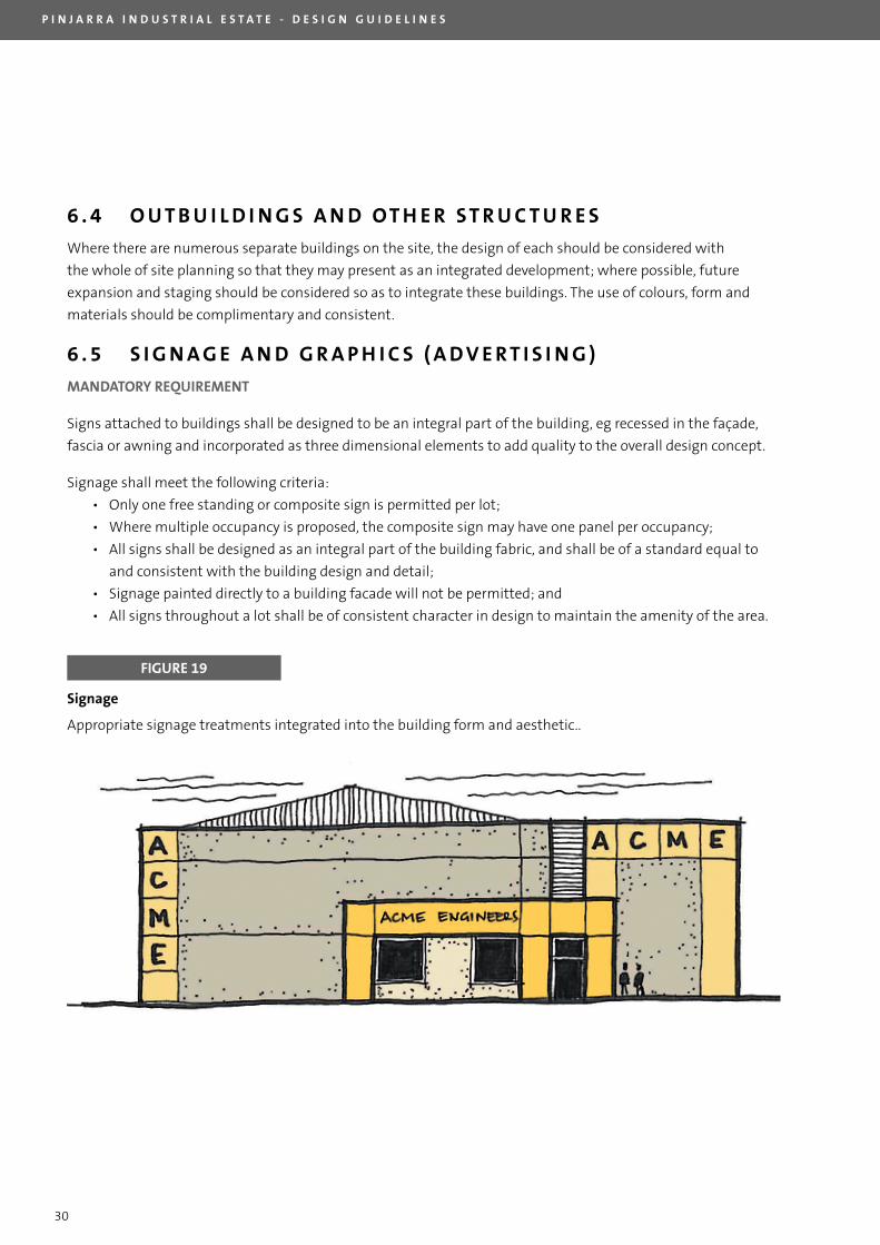
6 . 5 S I G N A G E A N D G R A P H I C S ( A D V E R T I S I N G )
MANDATORY REqUIREMENT
Signs attached to buildings shall be designed to be an integral part of the building, eg recessed in the façade,
fascia or awning and incorporated as three dimensional elements to add quality to the overall design concept.
Signage shall meet the following criteria:
• Only one free standing or composite sign is permitted per lot;
• Where multiple occupancy is proposed, the composite sign may have one panel per occupancy;
• All signs shall be designed as an integral part of the building fabric, and shall be of a standard equal to
and consistent with the building design and detail;
• Signage painted directly to a building facade will not be permitted; and
• All signs throughout a lot shall be of consistent character in design to maintain the amenity of the area.
FIGURE 19
Signage
Appropriate signage treatments integrated into the building form and aesthetic..
P I N J A R R A I N D U S T R I A L E S T A T E - D E S I G N G U I D E L I N E S
31
7. DETAILED PROvISIONS
7 . 1 W E S T E R N P O W E R
Purchasers are encouraged to utilise the land in the Western Power easements. All development and
subsequent use of land on lots which are subject to an easement on title relating to a Western Power
transmission line are subject to compliance with Western Power’s Standard Easement Conditions. Conditions as
outlined in Appendix 4.
All applications for the use and development of land affected by a Western Power easement should be referred
to Western Power for their consideration. Western Power has provided the following advice with respect to
development within the easement area:
• Western Power does not permit ground levels to be altered without conducting a clearance
calculation to ensure the conductor height complies with the Australian Standard. This calculation
is done at the cost of the party changing the Status quo. If the minimum phase-ground clearance
can not be maintained, the proposal will be refused.
• lighting will be subject to both Western Power’s operational requirements, and the Australian
Standard regarding safe electrical clearances. Any calculations required to ensure the proposed
installation will meet the standard and WorkSafe regulation 3.64, will be carried out by Western
Power at the proponent’s cost.
• Any car park facilities installed within the easement must be for short term parking (business
parking) and can only be used by vehicles less than 4.5 metres in height including attachments.
Storage is not permitted with the easement.
• The installation of soak wells for stormwater control must be approved by Western Power.
Earthworks and installation of infrastructure in the easement must comply with WorkSafe
requirements for working near overhead powerlines. There will be a cost involved if the minimum
clearance can not be maintained, this involves permits for working near energised equipment,
and/or the cost of a shutdown if necessary. Western Power can not guarantee that a shutdown of
the transmission line is possible.
• Any metallic fence must be earthed to comply with Australian Standards. The proponent will need
to engage an electrical consultant to determine the extent of earthing required, if any. Western
Power will provide all electrical data requested by the electrical consultant.
Developers / designers are encouraged to liaise with Western Power’s Environment and land Management
Branch prior to the preparation of plans for any development in the vicinity of any Western Power easement.
Western Power customer contact number 13 1087.
7 . 2 WAT E R C O R P O R AT I O N T R U N K M A I N
The Water Corporation’s DN1400 Stirling Trunk Main traverses the site. Water Corporation guidelines titled,
“General Guidelines for Working on or in the Vicinity of Trunk and Bore Mains” can be obtained directly from the
office of the Water Corporation in leederville.
P I N J A R R A I N D U S T R I A L E S T A T E - D E S I G N G U I D E L I N E S
32
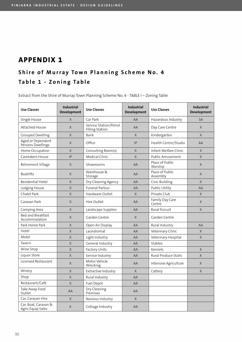
APPENDIX 1
S h i r e o f M u r r a y To w n P l a n n i n g S c h e m e N o . 4
Ta b l e 1 - Z o n i n g Ta b l e
Extract from the Shire of Murray Town Planning Scheme No. 4 - TABlE I – Zoning Table
Use ClassesIndustrial
DevelopmentUse Classes
Industrial Development
Use ClassesIndustrial
Development
Single House X Car Park AA Hazardous Industry SA
Attached House X Service Station/Petrol Filling Station AA Day Care Centre X
Grouped Dwelling X Bank X Kindergarten X
Aged or Dependent Persons Dwellings X Office IP Health Centre/Studio AA
Home Occupation X Consulting Room(s) X Infant Welfare Clinic X
Caretakers House IP Medical Clinic X Public Amusement X
Retirement Village X Showrooms AA Place of Public Worship X
Boatlifts X Warehouse & Storage AA Place of Public
Assembly X
Residential Hotel X Dry Cleaning Agency AA Civic Building X
lodging House X Funeral Parlour AA Public Utility AA
Chalet Park X Hardware Outlet X Private Club X
Caravan Park X Hire Outlet AA Family Day Care Centre X
Camping Area X landscape Supplies AA Rural Pursuit X
Bed and Breakfast Accommodation X Garden Centre X Garden Centre
Park Home Park X Open Air Display AA Rural Industry AA
Hotel X laundromat AA Veterinary Clinic X
Motel X light Industry AA Veterinary Hospital X
Tavern X General Industry AA Stables
Wine Shop X Factory Units AA Kennels X
liquor Store X Service Industry AA Rural Produce Stalls X
licensed Restaurant X Motor Vehicle Wrecking AA Intensive Agriculture X
Winery X Extractive Industry X Cattery X
Shop X Rural Industry AA
Restaurant/Café X Fuel Depot AA
Take Away Food Outlet AA Dry Cleaning
Premises AA
Car, Caravan Hire X Noxious Industry X
Car, Boat, Caravan & Agric Equip Sales X Cottage Industry AA
P I N J A R R A I N D U S T R I A L E S T A T E - D E S I G N G U I D E L I N E S
33
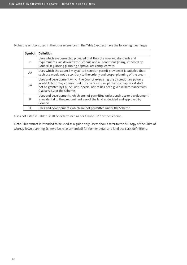
Note: the symbols used in the cross references in the Table 1 extract have the following meanings:
Symbol Definition
PUses which are permitted provided that they the relevant standards and requirements laid down by the Scheme and all conditions (if any) imposed by Council in granting planning approval are complied with.
AAUses which the Council may at its discretion permit provided it is satisfied that such use would not be contrary to the orderly and proper planning of the area.
SA
Uses and development which the Council exercising the discretionary powers available to it may approve under the Scheme except that such approval shall not be granted by Council until special notice has been given in accordance with Clause 5.5.2 of the Scheme.
IPUses and developments which are not permitted unless such use or development is incidental to the predominant use of the land as decided and approved by Council.
X Uses and developments which are not permitted under the Scheme
Uses not listed in Table 1 shall be determined as per Clause 5.2.3 of the Scheme.
Note: This extract is intended to be used as a guide only. Users should refer to the full copy of the Shire of
Murray Town planning Scheme No. 4 (as amended) for further detail and land use class definitions.
P I N J A R R A I N D U S T R I A L E S T A T E - D E S I G N G U I D E L I N E S
34
APPENDIX 2
N o n - R e s i d e n t i a l D e v e l o p m e n t S t a n d a r d s
P I N J A R R A I N D U S T R I A L E S T A T E - D E S I G N G U I D E L I N E S
35
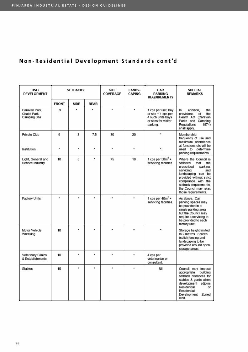
N o n - R e s i d e n t i a l D e v e l o p m e n t S t a n d a r d s c o n t ’d
P I N J A R R A I N D U S T R I A L E S T A T E - D E S I G N G U I D E L I N E S
36
APPENDIX 3
C o s s i l l a n d W e b l e y C o n s u l t i n g E n g i n e e r s
D r a w i n g N o . 5 8 5 6 - 0 1 - 6 0 0

P I N J A R R A I N D U S T R I A L E S T A T E - D E S I G N G U I D E L I N E S
37
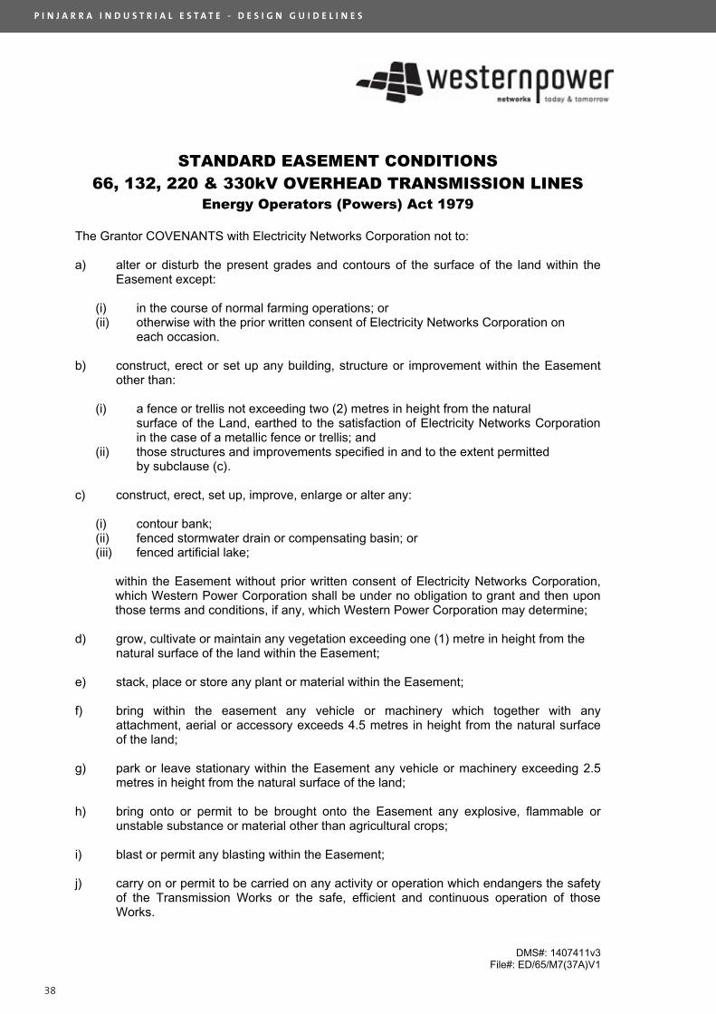
APPENDIX 4
W e s t e r n P o w e r S t a n d a r d
E a s e m e n t C o n d i t i o n s
P I N J A R R A I N D U S T R I A L E S T A T E - D E S I G N G U I D E L I N E S
38
DMS#: 1407411v3 File#: ED/65/M7(37A)V1
STANDARD EASEMENT CONDITIONS66, 132, 220 & 330kV OVERHEAD TRANSMISSION LINES
Energy Operators (Powers) Act 1979
The Grantor COVENANTS with Electricity Networks Corporation not to:
a) alter or disturb the present grades and contours of the surface of the land within the Easement except:
(i) in the course of normal farming operations; or (ii) otherwise with the prior written consent of Electricity Networks Corporation on
each occasion.
b) construct, erect or set up any building, structure or improvement within the Easement other than:
(i) a fence or trellis not exceeding two (2) metres in height from the natural surface of the Land, earthed to the satisfaction of Electricity Networks Corporation in the case of a metallic fence or trellis; and
(ii) those structures and improvements specified in and to the extent permitted by subclause (c).
c) construct, erect, set up, improve, enlarge or alter any:
(i) contour bank; (ii) fenced stormwater drain or compensating basin; or (iii) fenced artificial lake;
within the Easement without prior written consent of Electricity Networks Corporation, which Western Power Corporation shall be under no obligation to grant and then upon those terms and conditions, if any, which Western Power Corporation may determine;
d) grow, cultivate or maintain any vegetation exceeding one (1) metre in height from the natural surface of the land within the Easement;
e) stack, place or store any plant or material within the Easement;
f) bring within the easement any vehicle or machinery which together with any attachment, aerial or accessory exceeds 4.5 metres in height from the natural surface of the land;
g) park or leave stationary within the Easement any vehicle or machinery exceeding 2.5 metres in height from the natural surface of the land;
h) bring onto or permit to be brought onto the Easement any explosive, flammable or unstable substance or material other than agricultural crops;
i) blast or permit any blasting within the Easement;
j) carry on or permit to be carried on any activity or operation which endangers the safety of the Transmission Works or the safe, efficient and continuous operation of those Works.
P I N J A R R A I N D U S T R I A L E S T A T E - D E S I G N G U I D E L I N E S
39
DEPO
SITE
D PL
AN
12
11
5489
3ED
ITIO
NVE
RSIO
N
SHEE
TOF
SHEE
TS
UN
LODGED
VER
SIO
N
SUBJ
ECT
TO
SCALE
:
DATE
FEE
PAID
ASS
ESS
No.
PURP
OSE
TYPE
PLAN
OF
FILE
DIST
RICT
TOW
NSIT
E
DOLA
FIL
E
LOCA
L AUT
HORI
TYLO
CALI
TY
I
Date
Lice
nsed
Sur
veyo
r
ED/V
ERAMEN
DMEN
TBY
DATE
SIGN
ATU
RE
SUBJ
ECT
PURP
OSE
STATU
TORY
REF
EREN
CECO
MMEN
TS
INTE
REST
S AND
NOT
IFIC
ATI
ONS
SEE
FORM
ERTE
NURE
TABL
E
AMEN
DMEN
TS T
ABL
E
ALL
DIS
TANC
ES A
RE IN
MET
RES
PO B
ox
117,
So
uth
Pe
rth
WA
695
1Te
lep
ho
ne
: (08
) 94
74 1
099
Fac
simile
: (08
) 9
474
1093
Ema
il: m
ap
s@m
ap
surv
ey.
co
m.a
u
I.S.
C.
LEGA
LCO
MPO
NENT
CERT
IFIE
DCO
RREC
TFU
LL A
UDIT
F.S.
C.
LODG
ED
S.S.
A.
SURV
EYOR
'S C
ERTI
FICA
TE -
Reg
54
APP
ROVE
D
IN O
RDER
FOR
DEA
LING
S
FIEL
D BO
OK
FORM
ER T
ENUR
E
1 :5
000
at A
2 TYPE
OF
VALI
DATI
ON
DOCK
ETPL
AN
APP
ROVE
D BY
WES
TERN
AUS
TRALI
AN
PLANN
ING
COMMIS
SION
For
INSP
ECTO
R OF
PLA
NS &
SUR
VEYS
/ AUT
HORI
ZED
LAND
OFF
ICER
DATE
Dele
gate
d un
der
S. 1
6 P
& D
Act
200
5
DATE
DATE
INSP
ECTO
R OF
PLA
NS &
SUR
VEYS
/ AUT
HORI
ZED
LAND
OFF
ICER
ORIG
INLA
ND B
URDE
NED
BENE
FIT
TO
h
ereb
y ce
rtify
that
thi
spl
an is
acc
urat
e an
d is
a co
rrec
t re
pres
enta
tion
of t
he -
(a)
*sur
vey;
and
/or
(b)
*cal
cula
tions
fro
m m
easu
remen
ts,
[*de
lete
if in
appl
icabl
e], u
nder
take
nfo
r th
e pu
rpos
es o
f th
is pl
an a
nd t
hat
it co
mpl
ies
with
the
rel
evan
t writ
ten
law(s
) in
rela
tion
to w
hich
it is
lodg
ed.
ON
12.4
8
89°4
1'17
"
90°1
8'27
"
18.6
MOO
RES
1180
DP 2
5396
2
4D
5660
9
1483
DP 9
3537
1484
DP 9
3537
Nail
& Pl
ate
on F
ence
Pos
t
PINJ
ARR
A
D
N
DOC
G487
552E
MUR
RAY
SHIR
E OF
MUR
RAY
Mar
k P.
MARI
OTTI
"Ex
empt
Fro
m W
APC
App
rova
l"
POLLARD STREET
231°
24'1
"
231°24'1"
A
L
EH
J
K
186°14'11"
89°3
9'4"
233.
8824
0.37
120.
7424
3.36
NO
CROW
N
"Th
e di
men
sions
and
pos
ition
s of
the
se E
asem
ents
are
base
d on
acc
urat
e su
rvey
ed a
lignm
ents
."
OMOM
OM
MF
SUBD
IVIS
ION
5026
3-20
04 V
2
I
ELEC
TRIC
ITY C
ORPO
RATI
ONSE
E NO
TE '
Z'E
H
NOTE
'Z'
Gui
delin
e 1
(838
.35)
180°
1'21
"
B
EASE
MEN
T(W
ater
Sup
ply)
DOC
J246
929E
WATE
R CO
RPOR
ATI
ONSE
E NO
TE '
Z'
EASE
MEN
T
SEC
144
OF T
HE L
.A.A
.246.24
226.49
539.
89
451.
65
152.
2722
7.01
428.
15
190.
88
597.87342.59 354.99
270°21'25"
502
501
131.
48
297.4
48.8
7
16.7
7
134°19'5"
314°19
'5"
85°7
'10"
(697.58)
94°1
'31"
95°3
'48"
(583
.13)
502
500
48.8
7
297.4
117°
53'2
7"
17.09
451.
65
227.
01
428.
15
8.5
15.5
718
.59
131.
48
19.5
3155°
50'4
5"
155°
50'4
5"
144°26'38"157°42'25"
(583
.13)
168°16'1"
MOO
RES
RO
AD
D
500
502
LOTS
500
-502
ROAD
BN
OLO
TS 5
00 &
502
C
M
N
TITL
ELO
TFO
RMER
TEN
URE
ON P
LAN
/ DI
AGR
AM
FORM
ER T
ENUR
E TA
BLE
500
PT L
OT 3
22PT
LOT
328
LOT
1482
DP 2
1537
2DP
935
35DP
935
36LR
3034
/430
LR30
71/3
69
PT L
OT 3
28DP
935
35LR
3034
/430
501
PT L
OT 3
22DP
215
372
SEE
Enl.
'U'
SEE
Enl.
'Y'
ENLA
RGEM
ENT
'Y'
SCALE
1:100
0
AC
DK
LM
FOR
EASE
MEN
TS
SEE
ENLA
RGEM
ENT
'V'
ON S
HEET
2
EH
IJ
FOR
EASE
MEN
TS
SEE
ENLA
RGEM
ENT
'W'
ON S
HEET
2
BN
FOR
EASE
MEN
TS
SEE
ENLA
RGEM
ENT
'X'
ON S
HEET
2
BG 3
2(2)
13.
30
ENLA
RGEM
ENT
'U'
SCALE
1:100
0
1168
DP 2
5395
8
LOT
500
LM
IJ
KLO
T 50
0DO
C G4
9423
3EEL
ECTR
ICIT
Y C
ORPO
RATI
ONSE
E NO
TE '
Z'EA
SEMEN
T
AC
EASE
MEN
TDO
C G4
8755
2ELO
T 50
2EL
ECTR
ICIT
Y C
ORPO
RATI
ONSE
E NO
TE '
Z'
91°4
7'40
"or
ig
79°7'
2"ori
g
orig
p.orig
p.orig
235.
43
1275.35
198°42'55"
500
89.2
932h
a
502
0
ALL
DIS
TANC
ES A
RE IN
MET
RES
SCALE
1
: 500
0 @
A2
100
400
119178.4
102.
1918
7.7
249.
99
MAPS
Ref
: 94
183d
p-01
3dDP
5489
3#1.
CSD
12.5
499h
a4.
0279
ha
FINA
L
9934
910
2454
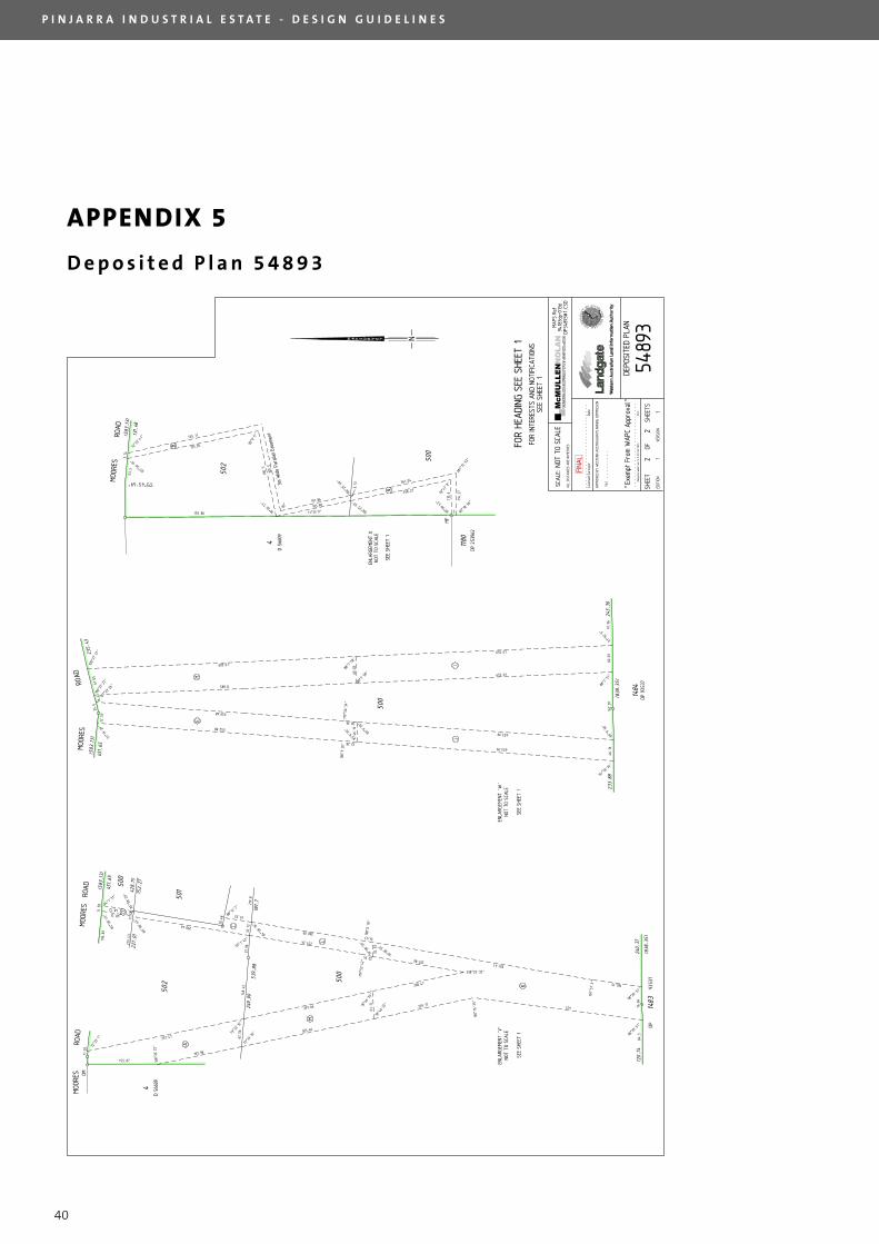
APPENDIX 5
D e p o s i t e d P l a n 5 4 8 9 3
P I N J A R R A I N D U S T R I A L E S T A T E - D E S I G N G U I D E L I N E S
40
N
502
3 90°1
8'56
"
114.
27
110.
6
100.
510
0.5
3.14
72°3
3'41
"
107°
26'1
9"
4D
5660
9
1180
DP 2
5396
2
53.5
155.86
3m W
ide
Para
llel E
asem
ent
281°
12'5
2"
133.05
135.11
90°0
'5"
90°
78°2
6'51
"
11°33'9" 89°3
9'43
"
1484
DP 9
3537
500
46.1
660
.03
32.28
653.99
46.1
660
.03
22.5
3
653.99
28.36
61.0
5
652.01
652.01
85°9
'29" 85°9
'29"
100°
37'2
7" 88°7
'58"
88°7
'58"
94°5
0'24
"
85°9
'36"
88°7
'51"
91°5
2'9"
180°
3'26
"17
9°56
'34"
91°1
9'29
"
100°
37'2
7"10
7°23
'26"
61.1
732
.53
76.8
4
207.86
32.1
2
501.41
16.43
62.5
6
11.0
3
22.24
11.5
8
11.5
8
20.4
8
431
160.15
260.09
193.98
357.47
229.77297.66
208.47
303.46
257.24
48.12
290.46
61.33
155.87
48.12
73°3
3'32
"
84°5
8'18
"
85°5
8'43
"
78°4
6'33
"
85°5
8'29
"
168°
26'2
2"
73°3
3'32
"
78°4
6'33
"
98°2
9'51
"
181°
51'3
"
338°25'32"
79°3
8'59
"
79°38'
59"
98°2
9'51
"
160°
16'3
5"
72°3
3'7"
180°
6'18
"
179°
53'4
2"
88°1
2'7"
95°1'
42"
85°5
8'43
"
94°1
'31"
193.98191.86
3.13
106°
25'5
9"
106°2
5'59
"
B
N
OM
4D
5660
9
MOO
RES
ROAD
(583
.13)
451.
65
MOO
RES
RO
AD
A
M
C
D
L
K
JI
EH
219.
8
148.
42
539.
88
196.
83
215.
43
500
501
502
428.
1522
7.01
152.
27
500
84.3
1483
(838
.35)
120.
7424
0.37
DP
9
3537
(838
.35)
91.9
616
2.07
243.
3623
3.88
16.6
1
235.
43
451.
65
(583
.13)
173°45'49"
500
MOO
RES
ROAD
131.
48
(583
.13)
MOO
RES
R
OAD
SCALE
:
ALL
DIS
TANC
ES A
RE IN
MET
RES
FILE
DEPO
SITE
D PL
AN
22
11
5489
3ED
ITIO
NVE
RSIO
N
SHEE
TOF
SHEE
TS
UN
LODGED
VER
SIO
N
Lice
nsed
Sur
veyo
rDa
te
FOR
HEADI
NG S
EE S
HEET
1
NOT
TO S
CALE
FOR
INTE
REST
S AND
NOT
IFIC
ATI
ONS
SEE
SHEE
T 1
APP
ROVE
D BY
WES
TERN
AUS
TRALI
AN
PLANN
ING
COMMIS
SION
DATE
Dele
gate
d un
der
Sec
16 P
& D
Act
200
5
"Ex
empt
Fro
m W
APC
App
rova
l"
358.27
361.04
ENLA
RGEM
ENT
'V'
NOT
TO S
CALE
SEE
SHEE
T 1
ENLA
RGEM
ENT
'W'
NOT
TO S
CALE
SEE
SHEE
T 1
ENLA
RGEM
ENT
XNO
T TO
SCA
LE
SEE
SHEE
T 1
MF
78°4
7'8"
559.68
552.88
24.6
589.8
603.01
249.
9918
7.7
MAPS
Ref
9418
3dp-
013d
DP54
893#
1.CS
D
FINA
L
37.9
6
APPENDIX 5
D e p o s i t e d P l a n 5 4 8 9 3

P I N J A R R A I N D U S T R I A L E S T A T E - D E S I G N G U I D E L I N E S
41

P I N J A R R A I N D U S T R I A L E S T A T E - D E S I G N G U I D E L I N E S
42

P I N J A R R A I N D U S T R I A L E S T A T E - D E S I G N G U I D E L I N E S
43

APPENDIX 4
P r e s c r i b e d P l a n t S p e c i e s
Prescribed Plant Species
BOTANICAL NAME COMMON NAME HEIGHT SPREAD
Feature Trees
Agonis flexuosa WA Peppermint 10m 8m
Corymbia ficifolia Red Flowering Gum 10m 8m
Eucalyptus caesia ssp. magna Silver Princess 6m 4m
Melaleuca leucadendra Weeping Paperbark 10m 5m
Allocasuarina fraseriana WA Sheok 9m 6m
Endemic Large Tree Planting
Corymbia calophylla Marri 30m 15m
Eucalyptus marginata Jarrah 25m 15m
Eucalyptus rudis Flooded Gum 25m 10m
Eucalytus wandoo Wandoo 20m 10m
Endemic Small Tree Species
Banksia attenuate Slender Banksia 6m 3m
Banksia littoralis Swamp Banksia 5m 3m
Banksia menziesii Firewood Banksia 5m 3m
Melaleuca rhaphiophylla Swamp Paperbark 10m 5m
Large Shrubs
Accacia Cyclops Red Eye Wattle 2m 3m
Callistemon glaucus Albany Bottlebrush 2m 1.5m
Grevillia olivacea Olive Grevillea 2m 2m
Melaleuca incana Grey Honey Myrtle 2m 2m
Small Shrubs (Feature Planting)
44
WESTERN AUSTRALIAN LAND AUTHORITY
LEVEL 3 WESFARMERS HOUSE
40 THE ESPLANADE PERTH
WESTERN AUSTRALIA 6000
T (08) 9482 7499 F (08) 9481 0861
www.landcorp.com.au LC 0
19
5