Ping Pong Product Manual - Round · PDF file5 6- Downloading Firmware to the PingPong board:...
18
1 Ping Pong Product Manual Rev .04 – 26-05-2015
-
Upload
hoangthuan -
Category
Documents
-
view
222 -
download
2
Transcript of Ping Pong Product Manual - Round · PDF file5 6- Downloading Firmware to the PingPong board:...

1
Ping Pong
Product Manual
Rev .04 – 26-05-2015

2
Contents
1- Product Description ........................................................................................................................ 3
2- Key Benefits .................................................................................................................................... 3
3- Product Features ............................................................................................................................. 3
4- Interfaces ........................................................................................................................................ 4
5- Development Enviroment: .............................................................................................................. 4
6- Downloading Firmware to the PingPong board: ............................................................................. 5
a- PIC Programmer: .......................................................................................................................... 5
b- USB Boot Loader: ......................................................................................................................... 5
7- PIN Outs: ......................................................................................................................................... 6
8- RF Connectors: ................................................................................................................................ 7
9- Inter-modules Connections: ............................................................................................................ 7
10- Firmware Development: ............................................................................................................. 8
1- PPR_cdc_com_Port [1]: .............................................................................................................. 10
2- PPR_tcpip_client_server [2]: ...................................................................................................... 11
3- PP_tcpip_tcp_server[3]: ............................................................................................................. 15
4- PP_cdc_com_port_single[4]: ...................................................................................................... 16
5- PP_State_machine: .................................................................................................................... 17
11- References: ............................................................................................................................... 18

3
1- Product Description The Round Solutions PingPong is an embedded IoT/M2M hardware platform made for Software Developers. The platform supports extension boards that add unlimited capabilities. It can be used to easily make physical devices that connect to the web. It’s literally plug, push and play. PingPong comes with both wired and wireless connectivity. The device is available in two open-source SW versions. While the RTOS version comes with the world’s fastest 32-bit microcontroller running in C/C++, the Linux version uses the powerful ARM Cortex processor for even more functionality and applications. PingPong base circuit boards also have a high speed Telit cellular module, a high accuracy positioning component for the Global Navigation Satellite System (GNSS), Ethernet, USB, CANBUS among other items. The Evaluation Kit comes with a dedicated M2M/IoT SIM card and connectivity to a cloud platform.
2- Key Benefits • Easy to integrate with other devices & sensors using USB HS, UART, Ethernet, SPI, I2C, CAN, and
user definable GPIOs • Increased connectivity performance with 2G/3G/4G, Wi-Fi and Bluetooth • Ideal platform for m2m applications and mobile data and computing devices with ultra-compact
design and extended operating temperature range • Combines high-speed wireless connectivity combined with embedded multi-constellation high-
sensitivity positioning GPS + GLONASS receiver • Internet friendly with integrated TCP/IP and UDP/IP stacks • Simple drop-in migration and technology design reuse path to 2G, 3G and 4G² with any Telit
xE910 cellular module • Over-the-Air firmware update • Wide range power supply input 9-60 V DC
3- Product Features • IoT Gateway with wired and wireless communication channels and interfaces
• Extendable through an unlimited number of Plug’n’Play hardware extension boards
• Wireless communication: Telit XE910 cellular family
o 2G, 3G and 4G²
• High Performance GNSS: Telit SL869
o GPS, Glonass, Galileo
o For Tracking, Timing and Dead Reckoning (available on request)
• 2x SIM card holder and SIM on chip
• Watchdog: Hardware Watchdog for the microcontroller
• Configurable over Ethernet, USB and/or SMS
• Out of the box connectivity with
o Cumulocity IoT Cloud Platform
o Telit m2mAIR Cloud
• TCP and UDP Data Protocols
• Accelerometer on board
• Magnetometer on board (E-Compass)
• RTOS Version:
o World’s fastest 32-bit microcontroller with 200 MHz (Microchip PIC32MZ)
o 4 MB Flash memory
• Linux Version:
o ARM Cortex A8 Processor
4
o 32 MB Flash memory
o 128 MB RAM
4- Interfaces • Connectors for unlimited stackable extension boards
• Ethernet interface
• USB interface
• USB interface directly with the Telit Cellular module
• 1 x CAN interface
• 2 x Frequency inputs
• 2 x Analog inputs
• 4 x Three state logic inputs
• 4 x NMOSFET outputs
• 2 x Current measurement inputs (24 bits resolution with galvanic isolation)
• 1 x 1-Wire interface
• Antenna Connectors
o GSM: U.FL Connector
o GNSS: U.FL Connector
5- Development Enviroment:
The RTOS version of the PingPong board uses the Microchip PIC32MZ2048ECM144 microcontroller.
MPLABX from microchip along with XC32 complier are the IDE and complier used in developing
applications and modifying the firmware. Both the IDE and the complier can be downloaded from
Microchip’s website. The IDE is free of charge and the complier comes with 60 days free trial and
then a license can be purchased or can be used for free with some limitations.
Microchip MPLABX: http://www.microchip.com/pagehandler/en-us/family/mplabx/
Microchip XC32 Complier: http://www.microchip.com/pagehandler/en_us/devtools/mplabxc/
It is also strongly recommended to download Microchip MPLAB Harmony Integrated Software
Framework. Microchip MPLAB Harmony allows the developer to configure the project to use
different stacks and configures peripherals easily. It can be found on this link:
http://www.microchip.com/pagehandler/en-us/devtools/mplabharmony/home.html
Refer to Installing a Plug-in Module inside the MPLAB Harmony help file for a guide to add it as a
plug in to the MPLABX IDE.
MPLAB Harmony comes with a set of examples that demonstrates the use of all the peripherals. All
examples can be configured to use the Microchip PIC32MZ2048ECM144 microcontroller by changing
it from the project properties, and then launching the MPLAB Harmony configurator to generate
compatible code for the new Microcontroller without deleting any of the added code such as USB
descriptors.

5
6- Downloading Firmware to the PingPong board: a- PIC Programmer:
The PingPong board has 5 SMD pins for downloading a firmware to the microcontroller on board.
The pins are referenced in the picture below and are from right to left: Master clear (MCLR), VDD,
GND, PGD, and PGC. A non-expensive programmer is Microchip PicKit3 programmer which can be
used to download the firmware. Pinouts are shown below. Other programmer and emulators such
as ICD3 and REAL ICE are available from Microchip for
extensive debugging.
Fig (a)
The Microchip PICKit3 is integrated with MPLABX and the firmware can downloaded directly from
the IDE when it is connected to it.
b- USB Boot Loader:
Alternatively, hex files can be
downloaded via USB CDC. Digital input 4
(DI4) has to be tied to ground to lunch
the Boot Loader in the PingPong on
power up. The Bootloader software is
used to download hex files. The steps
are Connect � Load Hex File �Erase �
Program � Verify. As USB CDC creates a
virtual COM Port, the user has to select
the proper COM port and set the baud
are to 115200 for prompt download of
hex files. Fig (b)
Once Connect is clicked, the application requests the version of the boot loader inside the
PingPong. The current version should be higher than 1.4. Hex files that will be downloaded with the
Projects output that will be downloaded using the Bootloader should have their the linker script

6
“app_p32MZ.ld” added to the linker folder
before compilation. Each project has its own
linker script inside the src folder.
7- PIN Outs:
The picture on the right shows the pinout of the PingPong board. The table below provides a
description about each pin.
Fig (c)
Pin Number Pin Name Pin Description
1 VIN Input voltage to the board. 9 to 60VDC
2 GND Ground input to the board
3 1WD 1 Wire data interface
4 1W-GND 1W-GND interface (with isolation)
5 1W-PWR 1W-Power interface (with Isolation)
6 DO4 Digital output (PMOSFET) – outputs voltage equal VIN when triggered
7 DO2 Digital output (NMOSFET) - outputs GND when triggered
8 DO1 Digital output (PMOSFET) – outputs voltage equal VIN when triggered
9 DO3 Digital output (NMOSFET) - outputs GND when triggered
10 AI2 Analog input 2. 0-30 VDC input with 10 bits resolution
11 DI1 Digital Input 1. 0.7 to 30VDC DC to trigger a logic 1
12 DI2 Digital Input 2. 0.7 to 30VDC DC to trigger a logic 1
13 DI4 Digital Input 4. 0.7 to 30VDC DC to trigger a logic 1
14 DI3 Digital Input 3. 0.7 to 30VDC DC to trigger a logic 1
15 AI1 Analog input 1. 0-30 VDC input with 10 bits resolution
16 IGND Ground from the isolated part of the current measurement circuit
17 CI1+ Current input 1 + (4-20mA current measurement with isolation)

7
18 CI1- Current input 1 -
19 CI2+ Current input 2 + (4-20mA current measurement with isolation)
20 CI2- Current input 2 -
21 CANH CAN High
22 CANL CAN Low
23 FI1 Frequency counter input 1
24 FI2 Frequency counter input 1
8- RF Connectors:
The PingPong board has three UFL connectors on board as shown in the picture below.
Fig (d)
The GNSS connector has a 3V DC voltage to power the active antenna connected to it.
9- Inter-modules Connections:
The following figure shows the inter connections between the Microchip PIC32 microcontroller and all
the other modules on
board:
Fig (e)
PIC32
XE910
Module UART1
UART2 SL869
GNSS
SPI 5
Flash
Memory
4MB
SQI
Accelerometer Magnetometer
I2C
2
CAN
Transceiver CAN
SPI 4 4-20mA
measurement
Ethernet
USB I/O ADC
1-Wire

8
10- Firmware Development:
Before starting the development, we recommend that you make yourself familiar with Microchip
MPLABX IDE and MPLAB Harmony. Note that MPLAB Harmony has to be added as a plugin to the All
the examples we provide have been setup using MPLAB Harmony. We provide examples of source
code that show how to develop a code for the Ping Pong in addition to how to establish
communications between the microcontroller and interconnected module. The examples include
RTOS, Ethernet, USB CDC, communicating with Telit Cellular module, receiving GPS NMEA messages,
writing and reading to memory, and reading and writing to Inputs and Outputs.
The Ping Pong uses a 24MHz clock oscillator. So the oscillator configuration bits should be EC. The
following configuration bits are recommended (and mandatory when using the Boot loader):
/*** DEVCFG0 ***/
#pragma config DEBUG = ON
#pragma config JTAGEN = OFF
#pragma config ICESEL = ICS_PGx1
#pragma config TRCEN = ON
#pragma config BOOTISA = MIPS32
#pragma config FECCCON = OFF_UNLOCKED
#pragma config FSLEEP = OFF
#pragma config DBGPER = PG_ALL
#pragma config EJTAGBEN = NORMAL
#pragma config CP = OFF
/*** DEVCFG1 ***/
#pragma config FNOSC = SPLL
#pragma config DMTINTV = WIN_127_128
#pragma config FSOSCEN = OFF
#pragma config IESO = OFF
#pragma config POSCMOD = EC
#pragma config OSCIOFNC = OFF
#pragma config FCKSM = CSDCMD
#pragma config WDTPS = PS1048576
#pragma config WDTSPGM = STOP
#pragma config FWDTEN = OFF
#pragma config WINDIS = NORMAL
#pragma config FWDTWINSZ = WINSZ_25
#pragma config DMTCNT = DMT31
#pragma config FDMTEN = OFF
/*** DEVCFG2 ***/
#pragma config FPLLIDIV = DIV_3
#pragma config FPLLRNG = RANGE_5_10_MHZ
#pragma config FPLLICLK = PLL_POSC
#pragma config FPLLMULT = MUL_50
#pragma config FPLLODIV = DIV_2

9
#pragma config UPLLFSEL = FREQ_24MHZ
#pragma config UPLLEN = ON
/*** DEVCFG3 ***/
#pragma config USERID = 0xffff
#pragma config FMIIEN = OFF
#pragma config FETHIO = ON
#pragma config PGL1WAY = ON
#pragma config PMDL1WAY = ON
#pragma config IOL1WAY = ON
#pragma config FUSBIDIO = OFF
/*** BF1SEQ0 ***/
#pragma config TSEQ = 0xffff
#pragma config CSEQ = 0xffff
To check the various Harmony configurations used, please open the MPLAB Harmony Configurator
from within MAPLABX, which is found under Tools� Embedded. All the files related to RTOS, TCPIP,
USB CDC, SQI, UART, SPI, and I2C are added to the code automatically by MAPLAB Harmony. The
Ping Pong board uses the chip LAN8740A from Microchip as Ethernet Transceiver, SST26VF032 from
microchip as the flash memory, MCP3910 for 4-10 ma Current measurement, FXOS8700CQ from
Freescale as accelerometer and magnetometer. Please refer to the datasheet of these ICs for more
details information on their utilization in the board if needed.
There are 5 different MPLABX demo projects that can be downloaded from Round Solutions
website. These projects demonstrate the use of FreeRTOS and state machine code. They include
examples about the use of TCPIP, USB CDC, communication with Telit modules, reading GPS NMEA
messages, and reading and writing to IOs.
The purpose of this document is not to explain how FreeRTOS works, how Telit cellular modules
work, or to explain the stack of TCPIP, USB and other modules. It just demonstrates how they are
used in the examples provided, and the users can use these examples as a base for their application
development on the Ping Pong solely without any royalty fee paid to Round Solutions. To get more
information about the functionality of the modules, please refer to the datasheets of each.
The projects available at Round Solutions websites can be downloaded at the following address:
http://www.roundsolutions.biz/media/pdf/EVK-PCB-HEDGN-R1501_PingPong%20SourceCode-
zip%20file.zip
1 - PPR_cdc_com_port_dual: A project that uses RTOS and creates two virtual COM ports (USB CDC)
2- PPR_tcpip_client_server: A project that uses FreeRTOS and sets up TCPIP communications.
3- PP_tcpip_tcp_server: a project that uses state machine to demonstrates the use of TCPIP stack
4- PP_single_com_port: a project that uses state machine to demonstrates the use of USB CDC
stack
5 -PP_State_machine: a project that demonstrates the use of state machines to communicate with
the Telit Cellular module on board, reads GPS NMEA messages, writes to and reads from memory
and IOs.

10
Projects 1, 2, 3, and 4 are based on examples taken from Microchip Harmony and modified to work
on the Ping Pong board, copy rights for Microchip applies here as listed in MPLAB Harmony help
document.
1- PPR_cdc_com_port_dual [1]:
This RTOS based demonstration application creates a USB CDC Device that enumerates as two
serial ports on the USB Host personal computer. This application demonstrates the ability of the
MPLAB Harmony USB Stack to operate in a Real-Time Operating System (this example uses
FreeRTOS) and to support multiple instances of the same device class.
Description:
To build this project, you must copy the project to the following location: <install-
dir>/apps/rtos/freertos/ and then open the PPR_cdc_com_port_dual.X project in MPLAB X IDE.
<install-dir> if not changed by the user is: C:\microchip\harmony\vxxxxx
Where vxxxxx depends on which version of MPLAB Harmony is installed.
The demonstration application contains six tasks. A description of these tasks is as follows:
• The FrameworkTasks task is created in the SYS_Tasks function. This task calls the USB Device
Layer Tasks function (USB_DEVICE_Tasks). The priority of this task is designed to be the lowest
when compared to the priorities of other tasks. Hence this tasks runs when all other tasks are either
in blocked state or not ready to run.
• The APP_USB_DEVICE_Open task is created in the APP_Tasks function. This task creates all the
semaphores and message queues needed for the application. It creates 4 tasks which implement the
application logic. It attempts to open the Device Layer and then blocks on the
xSemaphoreBlockUsbConfigure semaphore. The xSemaphoreBlockUsbConfigure is given in the
USB Device Layer Event Handler when the device is configured by the Host. The tasks then resumes
the 4 application logic tasks and suspends itself.
• The APP_CDC1Read Task is created in the APP_USB_DEVICE_Open task. It schedules a read on
the CDC1 instance and then blocks on the CDC1 instance xSemaphoreCDCReadComplete
semaphore. This semaphore is given in the Read Complete event in the CDC Application Event
Handler. The tasks will then post the data that it has received from the Host to the CDC 1 instance
Message Queue.
• The APP_CDC2Read Task is created in the APP_USB_DEVICE_Open task. It schedules a read on
the CDC2 instance and then blocks on the CDC2 instance xSemaphoreCDCReadComplete
semaphore. This semaphore is given in the Read Complete event in the CDC Application Event
Handler. The tasks will then post the data that it has received from the Host to the CDC 1 instance
Message Queue.
• The APP_CDC1Write Task is created in the APP_USB_DEVICE_Open task. It blocks on the CDC 2
message queue. When APP_CDC2Read Task posts a message to this queue, the APP_CDC1Write
gets ready to run and the writes the data (received on the queue) to the CDC 1. This data is then
transferred to the Host.

11
• The APP_CDC2Write Task is created in the APP_USB_DEVICE_Open task. It blocks on the CDC 1
message queue. When APP_CDC1Read Task posts a message to this queue, the APP_CDC2Write
gets ready to run and the writes the data (received on the queue) to the CDC 2. This data is then
transferred to the Host.
For more information about USB CDC stack, please refer to Framework Help/USB Libraries
Help/USB Device Help/USB Device CDC Library in MPLAB Harmony documentation.
2- PPR_tcpip_client_server [2]:
The TCP/IP Client Server application, PPR_tcpip_client_server, demonstrates how to run multiple
TCP and UDP servers and clients using the TCP/IP Stack in an RTOS environment. The
demonstration also has the HTTP Web server running using the Non-Volatile Memory (NVM)
Microchip Proprietary File System (MPFS) to store the web pages in the internal PIC32 Flash.
Description
To build this project, you must copy the project to the following location: <install-
dir>/apps/rtos/freertos/ and then open the PPR_tcpip_client_server.X project in MPLAB X IDE.
<install-dir> if not changed by the user is: C:\microchip\harmony\vxxxxx
Where vxxxxx depends on which version of MPLAB Harmony is installed.
This demonstration runs IPv4 only on the Ethernet interface. To view the Web page hosted by the
demonstration application, open a Web browser and direct it to the board running the HTTP server by
typing the URL in the address bar (for example, http://mchpboard_e), and then pressing Enter.
Notes
1. The NetBIOS name of the TCP/IP application is specified at the time the TCP/IP stack is initialized,
which is usually in the hostName member of the tcpip_stack_init.c::
TCPIP_HOSTS_CONFIGURATION structure. The NetBIOS service must be enabled for the PIC32
demonstration to respond to NetBIOS queries (the NetBIOS service is enabled by default for this
demo). Alternatively, you can use the IPv4 of the board directly, for example, http://192.168.1.115.
2. The IPv4 address can be obtained from running the TCP/IP Discovery application on the PC side.
It requires that the TCP/IP Announce module is enabled when building the stack (the Announce
module is enabled by default in this application).
To use the advanced features of this demonstration, a system console must be enabled for the
application. The configuration has Telnet enabled by default. A Telnet connection could be used for
delivering the commands needed by the application. The username for telnet is “admin” and the
password is “microchip”
TCP/IP Tasks
There are four TCP/IP tasks in the application that demonstrate the use of IPv4 TCP and UDP
sockets in a multi-threaded system. Each of these tasks implements (and registers with the system
command processor) specific commands. The commands allow the corresponding sockets to be

12
opened and to start the communication with the remote hosts. On all hosts, the server sockets must
first be opened, and then have the client sockets connect to them. There are also commands for
configuring each socket/communication channel. Following the model in this application, extra
commands could be added for any of the tasks to achieve desired operation. Each of these
communication channels can be exercised simultaneously or in turn. For the purposes of the
demonstration, at least two different communication channels should be opened simultaneously to
put in evidence the multi-threaded behavior. A common scenario listing the console commands and
steps needed for running this demonstration would be: 1. Start app1 – TCP server:
• Start the PIC32 TCP server socket that listens on port 9760 by issuing the console
command: topen_s1<CR>
• On the client side (PC, etc.) open a client that connects over TCP to the PIC32 server
using port 9760. Use any network tools (“netcat”, etc.) or special applications, scripts
(TCL, Python, etc.) to transmit and receive data files.
2. Start app2 – TCP client:
• On the remote host side (PC, etc.) open a TCP server that listens for incoming
connections on port 9761. Use any network tools (netcat, etc.) or special applications,
scripts (TCL, Python, etc.) to receive (and transmit) data files. • Set the PIC32 client side
address and port for the server to connect to, for example: tsrv4_c1
192.168.100.101 9761<CR>
• Start the PIC32 TCP client socket by issuing the console command: topen_c1<CR>
3. Start app3 – UDP server:
• Start the PIC32 UDP server socket that listens on port 32323 by issuing the console
command: uopen_s1<CR>
• On the client side (PC, etc.) open a client that connects over UDP to the PIC32 server
using port 32323. Use any network tools (netcat, etc.) or special applications, scripts
(TCL, Python, etc.) to transmit and receive data files.
4. Start app4 – UDP client:
• On the remote host side (PC, etc.) open a UDP server that listens for incoming
connections on port 32324. Use any network tools (netcat, etc.) or special applications,
scripts (TCL, Python, etc.) to receive (and transmit) data files. • Set the PIC32 client side
address and port for the server to connect to, for example: usrv4_c1
192.168.100.101 32324<CR>
• Start the PIC32 UDP client socket by issuing the console command: uopen_c1<CR>
5. Now that you have the TCP/IP tasks running you can check the progress at run time. These
commands give the RX and TX statistics showing the amount of data transferred by each task:
• tstat_s1<CR>
• tstat_c1<CR>
• ustat_s1<CR>

13
• ustat_c1<CR>
6. Once the data transfer is completed, close the TCP/IP sockets (if not already closed by the
remote party):
• tclose_s1<CR>
• tclose_c1<CR>
• uclose_s1<CR>
• uclose_c1<CR>
TCP/IP Task Descriptions and Commands
app1.c::TCP server
This task uses a TCP server socket that listens by default on port 9760 to implement a simple
relay server. Any message that is received on that TCP port will be relayed back to the originating
socket. The following table lists and describes the available commands
Command Description:
topen_s1 Opens the listening TCP server socket.
tmsg_s1 Sends a short message using this socket to the remote client.
tabort_s1 Sends an abort/RST to the remote client and stops the communication.
tclose_s1 Closes the socket and stops the communication.
ttxsize_s1 Sets the TX buffer size of the server socket. The larger the buffer the more memory is
used by the socket and the more efficient is the transfer. Default value is 2048 bytes.
trxsize_s1 Sets the RX buffer size of the server socket. The larger the buffer the more memory is
used by the socket and the more efficient is the transfer. Default value is 2048 bytes.
tdisplay_s1 Enables displaying of the received messages locally to the system console.
tstat_s1 Displays/clears the current TX and RX statistics for the current connection.
app2.c::TCP client
This task uses a TCP client socket to connect to a remote server that listens by default on port
9761. Any message that is received by the socket can be optionally displayed locally. The client
has the possibility of sending messages to the server. The following table lists and describes the
available commands.
Command Description
topen_c1 Opens the TCP client socket.
tmsg_c1 Sends a message to the remote server.
14
tabort_c1 Sends an abort/RST to the server and stops the communication.
tclose_c1 Closes the socket and stops the communication.
tsrv4_c1 Sets the server IPv4 address and port. The default values are 192.168.100.101 and
9761.
tasync_c1 Enables the continuous transmission of messages to the server.
tdisplay_c1 Enables displaying of the received messages locally to the system console.
tstat_c1 Displays/clears the current TX and RX statistics for the current connection.
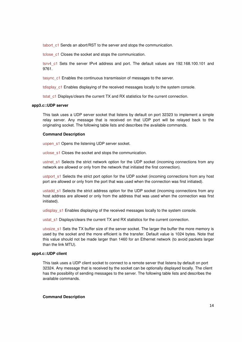
app3.c::UDP server
This task uses a UDP server socket that listens by default on port 32323 to implement a simple
relay server. Any message that is received on that UDP port will be relayed back to the
originating socket. The following table lists and describes the available commands.
Command Description
uopen_s1 Opens the listening UDP server socket.
uclose_s1 Closes the socket and stops the communication.
ustnet_s1 Selects the strict network option for the UDP socket (incoming connections from any
network are allowed or only from the network that initiated the first connection).
ustport_s1 Selects the strict port option for the UDP socket (incoming connections from any host
port are allowed or only from the port that was used when the connection was first initiated).
ustadd_s1 Selects the strict address option for the UDP socket (incoming connections from any
host address are allowed or only from the address that was used when the connection was first
initiated).
udisplay_s1 Enables displaying of the received messages locally to the system console.
ustat_s1 Displays/clears the current TX and RX statistics for the current connection.
utxsize_s1 Sets the TX buffer size of the server socket. The larger the buffer the more memory is
used by the socket and the more efficient is the transfer. Default value is 1024 bytes. Note that
this value should not be made larger than 1460 for an Ethernet network (to avoid packets larger
than the link MTU).
app4.c::UDP client
This task uses a UDP client socket to connect to a remote server that listens by default on port
32324. Any message that is received by the socket can be optionally displayed locally. The client
has the possibility of sending messages to the server. The following table lists and describes the
available commands.
Command Description

15
uopen_c1 Opens the UDP client socket.
umsg_c1 Sends a message to the remote server.
uclose_c Closes the socket and stops the communication.
usrv4_c1 Sets the server IPv4 address and port. The default values are 192.168.100.101 and
32324.
uasync_c1 Enables the continuous transmission of messages to the server.
udisplay_c1 Enables displaying of the received messages locally to the system console.
ustat_c1 Displays/clears the current TX and RX statistics for the current connection.
utxsize_c1 Sets the TX buffer size of the server socket. The larger the buffer the more memory is
used by the socket and the more efficient is the transfer. Default value is 1024 bytes. Note that
this value should not be made larger than 1460 for an Ethernet network (to avoid packets larger
than the link MTU).
For more information about TCPIP stack, please refer to Framework Help/TCP/IP Stack Libraries
Help in MPLAB Harmony documentation.
3- PP_tcpip_tcp_server[3]:
This configuration demonstrates creating an Internet server that uses the MPLAB Harmony TCP API
to create a TCP/IP echo server on port 9760.
Description:
To build this project, you must copy the project to the following location <install-dir>/apps/tcpip/ and
then open the PP_tcpip_server.X project in MPLAB X IDE.
<install-dir> if not changed by the user is: C:\microchip\harmony\vxxxxx
Where vxxxxx depends on which version of MPLAB Harmony is installed.
The demonstration does not offer any additional functionality through the serial port; however, the
current IP can be checked. As soon as a valid IP has been assigned through DHCP to the
demonstration, it is then ready to accept a TCP/IP connection on 9764. If DHCP is not available, the
device is assigned the IP 192.168.100.115. The demonstration will echo back everything it receives
along the connection. A USB cable can be connected to the micro-B USB connector on the bottom of
the PingPong. This will create a USB CDC device on the USB bus. To communicate with the
software, connect to this device though a standard terminal program and set the baud rate to 921,600
baud.
The application initializes the drivers, systems services, interrupts, and application in the function
SYS_Initialize() found inside the file system_init.c

16
The function SYS_Tasks(), found inside file system_tasks.c, maintains system services, Device
Drivers, Middleware & Other Libraries, and the application's state machine. It also runs USB HS
Driver Task Routine, and USB Device layer tasks routine.
The function APP_tasks() contains the state machine for the TCPIP stack.
For more information about TCP Module, please refer to Framework Help/TCP/IP Stack Libraries
Help/TCP Module in MPLAB Harmony documentation.
4- PP_cdc_com_port_single[4]:
This demonstration application creates a USB CDC Device that enumerates as a single COM port on
the host personal computer. The application demonstrates two-way communication between the USB
device and the personal computer host.
Description:
To build this project, you must copy the project to the following location <install-
dir>/apps/usb/device/. and then open the PP_cdc_com_port_single.X project in MPLAB X
IDE.
<install-dir> if not changed by the user is: C:\microchip\harmony\vxxxxx
Where vxxxxx depends on which version of MPLAB Harmony is installed.
This demonstration allows the device to appear like a serial (COM) port to the host. Attach the device to the host. If the host is a personal computer and this is the first time you have plugged this device into the computer, you may be prompted for a .inf file. The inf file is provided with the Source code of the project in a separate folder. Once the device is successfully installed, open up a terminal program, such as HyperTerminal and select the appropriate COM port. On most machines this will be COM5 or higher. Set the communication properties to 9600 baud, 1 Stop bit and No parity, with Flow Control set to None. Once connected to the device, typing a key in the terminal window will result in the attached device echoing the next letter. Therefore, if the letter 'b' is pressed, the device will echo 'c'.
Some terminal programs, like HyperTerminal, require users to click the disconnect button before
removing the device from the computer. Failing to do so may result in having to close and open the
program again to reconnect to the device.
The application initializes the drivers, systems services, interrupts, and application in the function
SYS_Initialize() found inside the file system_init.c
The function SYS_Tasks(), found inside file system_tasks.c, maintains system services, Device
Drivers, Middleware & Other Libraries, and the application's state machine. It also runs USB HS
Driver Task Routine, and USB Device layer tasks routine.
For more information about USB CDC, please refer to Framework Help/USB Libraries Help/USB
Device Help/USB Device CDC Library in MPLAB Harmony documentation.
17
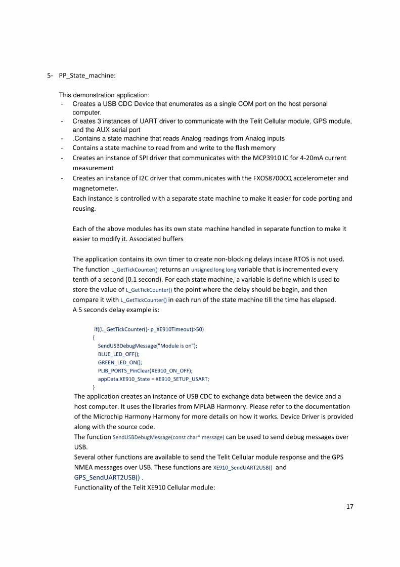
5- PP_State_machine:
This demonstration application:
- Creates a USB CDC Device that enumerates as a single COM port on the host personal
computer.
- Creates 3 instances of UART driver to communicate with the Telit Cellular module, GPS module,
and the AUX serial port
- .Contains a state machine that reads Analog readings from Analog inputs
- Contains a state machine to read from and write to the flash memory
- Creates an instance of SPI driver that communicates with the MCP3910 IC for 4-20mA current
measurement
- Creates an instance of I2C driver that communicates with the FXOS8700CQ accelerometer and
magnetometer.
Each instance is controlled with a separate state machine to make it easier for code porting and
reusing.
Each of the above modules has its own state machine handled in separate function to make it
easier to modify it. Associated buffers
The application contains its own timer to create non-blocking delays incase RTOS is not used.
The function L_GetTickCounter() returns an unsigned long long variable that is incremented every
tenth of a second (0.1 second). For each state machine, a variable is define which is used to
store the value of L_GetTickCounter() the point where the delay should be begin, and then
compare it with L_GetTickCounter() in each run of the state machine till the time has elapsed.
A 5 seconds delay example is:
if((L_GetTickCounter()- p_XE910Timeout)>50)
{
SendUSBDebugMessage("Module is on");
BLUE_LED_OFF();
GREEN_LED_ON();
PLIB_PORTS_PinClear(XE910_ON_OFF);
appData.XE910_State = XE910_SETUP_USART;
}
The application creates an instance of USB CDC to exchange data between the device and a
host computer. It uses the libraries from MPLAB Harmonry. Please refer to the documentation
of the Microchip Harmony Harmony for more details on how it works. Device Driver is provided
along with the source code.
The function SendUSBDebugMessage(const char* message) can be used to send debug messages over
USB.
Several other functions are available to send the Telit Cellular module response and the GPS
NMEA messages over USB. These functions are XE910_SendUART2USB() and
GPS_SendUART2USB() .
Functionality of the Telit XE910 Cellular module:

18
The PIC microcontroller uses UART1 with flow control to send data to and receive data from
the XE910 module. The Pin defined as XE910_Switch is used to provide or disconnect voltage
from the XE910 power pads. To provide power, this pin should be set to logic 1 using the
following function:
PLIB_PORTS_PinSet(XE910_Switch)
To disconnect power, the pin should be cleared using the following function:
PLIB_PORTS_PinClear(XE910_Switch);
After applying power to the module, the pin XE910_ON_OFF should be tied high
(PLIB_PORTS_PinSet(XE910_ON_OFF)) for at least 5 seconds to power up the module as shown in the
state machine for the XE910. Pin PWRMON goes high when the module is on.
The state machine sets an event handler to handle transmission or reception completion
events .
DRV_USART_BufferEventHandlerSet(appData.drvXE910UsartHandle,APP_BufferEventHandlerXE910Usart,(uintptr_t)
1);
Data is received from Telit XE910 module using the following function:
P_Message=DRV_USART_Read(appData.drvXE910UsartHandle,(uint8_t*)&appData.drvXE910UsartRxBuffer[appData.XE910_Buffer
_Index],100);
Where p_Message is the number of bytes that were read.
The remaining code in the state machine is an example on how to configure the module by
sending different AT commands and checking their response. These commands also contain
commands that get the IMEI of the module, set the APN, set the IP and Port of the server.
The PIC microcontroller uses SQI to write to and read from the Flash Memory on board. The
flash memory is 4MB in size. Please refer to the sample read and write code.
The memory can powered on/off through the pin SQI_PWR. If cleared
(PLIB_PORTS_PinClear(SQI_PWR)) then the memory will be powered on, and powered off otherwise.
The PingPong code contains a SL869 GPS module from Telit. The PIC microcontroller uses
UART2 without flow control to read NMEA messages from the module and send commands to
it if needed.
The function GPS_ParseNMEA() can be called every one second to extract longitude, latitude,
date, time, speed, heading, and number of visible satellites.
Function CheckIOs() checks the state of the digital inputs and populates the variables
DigitalInputx with one of either three state of the inputs: FLOATING, LOGIC_HIGH, or
LOGIC_LOW
11- References: [1] Microchip MPLAB Harmony Documentation: Applications Help/RTOS Demonstrations/FREERTOS
Demonstrations/cdc_com_port_dual
[2] Microchip MPLAB Harmony Documentation: Applications Help/RTOS Demonstrations/FREERTOS
Demonstrations/tcpip_client_server
[3] Microchip MPLAB Harmony Documentation: Applications Help/TCPIP Demonstrations/Demonstrations/
tcpip_client_server
[4] Microchip MPLAB Harmony Documentation: Applications Help/ USB Demonstrations/ Demonstrations/ Device/
cdc_com_port_single