
Pinal Airpark Water & Sewer Utility Assessment
53
Pinal Airpark Water & Sewer Utility Assessment Dibble Project No.: 101207.02 February 2013 Prepared For: 7500 North Dreamy Draw Drive Suite 200 Phoenix, Arizona 85020 P. 602.957.1155 F. 602.957.2838 www.dibblecorp.com 02/13/13
Transcript of Pinal Airpark Water & Sewer Utility Assessment
Pinal Airpark Water & Sewer Utility Assessment
Dibble Project No.: 101207.02
February 2013
Prepared For:
7500 North Dreamy Draw Drive Suite 200 Phoenix, Arizona 85020 P. 602.957.1155 F. 602.957.2838 www.dibblecorp.com
02/13/13

Dibble Engineering
February 2013
i Pinal Airpark
Water & Sewer Utility Assessment
Table of Contents
I. Airport Description ....................................................................................................................................... 1
II. Project Goals and Description ....................................................................................................................... 1
III. Water & Sewer Infrastructure Index ............................................................................................................. 3 A. Water Distribution Network ............................................................................................................................................. 3
1. Water System Inventory ........................................................................................................................................... 3 2. Water Distribution Network Photos ......................................................................................................................... 5
B. Sewer System Network ..................................................................................................................................................... 7 1. Sewer System Inventory ........................................................................................................................................... 7 2. Sewer System Photos ................................................................................................................................................ 7
IV. Vulnerability Assessment ............................................................................................................................. 8 A. Life Safety & Public Health Concerns ................................................................................................................................ 8
1. Fire Protection / Non‐Potable Connection ................................................................................................................ 8 2. Wastewater Collection .............................................................................................................................................. 9
B. System Redundancy & Reliability ...................................................................................................................................... 9 1. Water Supply ............................................................................................................................................................. 9 2. Water Storage ......................................................................................................................................................... 10 3. Booster Pumping Capacity ...................................................................................................................................... 10 4. Water Distribution System Integrity ....................................................................................................................... 10 5. Sewer System .......................................................................................................................................................... 10
C. Maintenance / Rehabilitation / Replacement ................................................................................................................. 10 D. Capacity for Expansion .................................................................................................................................................... 11
V. Recommendations ..................................................................................................................................... 11
List of Figures
Figure 1 – Airport Overview Drawing................................................................................................................................................ 2
List of Tables
Table 1 – Water System Inventory .................................................................................................................................................... 3 Table 2 – Sewer System Inventory .................................................................................................................................................... 7 Table 3 – Recommendations .......................................................................................................................................................... 12
Appendices
Appendix A – Utility Mapping, As‐Builts, Other Utility Data
Appendix B – Inventory of Water Infrastructure & Vulnerability Assessment
Appendix C – Inventory of Sewer Infrastructure & Vulnerability Assessment
Appendix D – Engineer’s Opinion of Probable Capital Cost
02/13/13

Dibble Engineering
February 2013
1 Pinal Airpark
Water & Sewer Utility Assessment
I. Airport Description
Pinal Airpark (Airport or MZJ) is situated approximately five miles northwest of the Town of Marana and
approximately 30 miles northwest of the City of Tucson, Arizona. The Airport is approximately one mile
west of Interstate 10, just north of the Pinal/Pima County line. The elevation of the Airport is
approximately 1,891 feet above Mean Sea Level (MSL). While Pinal Airpark is owned by Pinal County,
the Airport is currently leased to Marana Aerospace Solutions.
Pinal Airpark primarily serves as an aircraft storage and maintenance facility for Marana Aerospace
Solutions, but other users such as the Department of Defense, Arizona Army National Guard, and a
flight‐training school utilize the facility as well. The Airport is heavily secured and monitored 24 hours
daily, and is not currently considered a public‐use facility. The 2011‐2015 National Plan of Integrated
Airport Systems (NPIAS) classifies MZJ as a General Aviation Airport.
The airfield consists of one asphalt concrete pavement runway (12‐30) approximately 6,850’ long by
150’ wide. The runway is served by one parallel taxiway, and four connecting taxiways. All facilities can
be seen in the Airport Layout Drawing (as submitted by SFC Engineering Company 1991) in Appendix A.
An aerial image of the site titled, Airport Overview Drawing, is included as page 2 of this report. The
current Airport Reference Code (ARC) for MZJ is Approach Category/Design Group D‐V.
II. Project Goals and Description
The Pinal Airpark water and wastewater utilities will eventually transition from operation, maintenance
and management by the onsite tenant to operation and maintenance and management by Pinal County.
In advance of the transition, Pinal County desires to complete a system inventory and vulnerability
assessment of the existing infrastructure systems.
The intent of this assessment is to document the current condition and operation of the water and
wastewater systems and to provide guidance for developing a prioritized approach and conceptual costs
for system analyses and improvements.
The goals of this study are to:
Index the existing water & sewer infrastructure
Assess the vulnerability of the water & sewer infrastructure
Provide recommendations for future actions


Dibble Engineering
February 2013
3 Pinal Airpark
Water & Sewer Utility Assessment
III. Water & Sewer Infrastructure Index
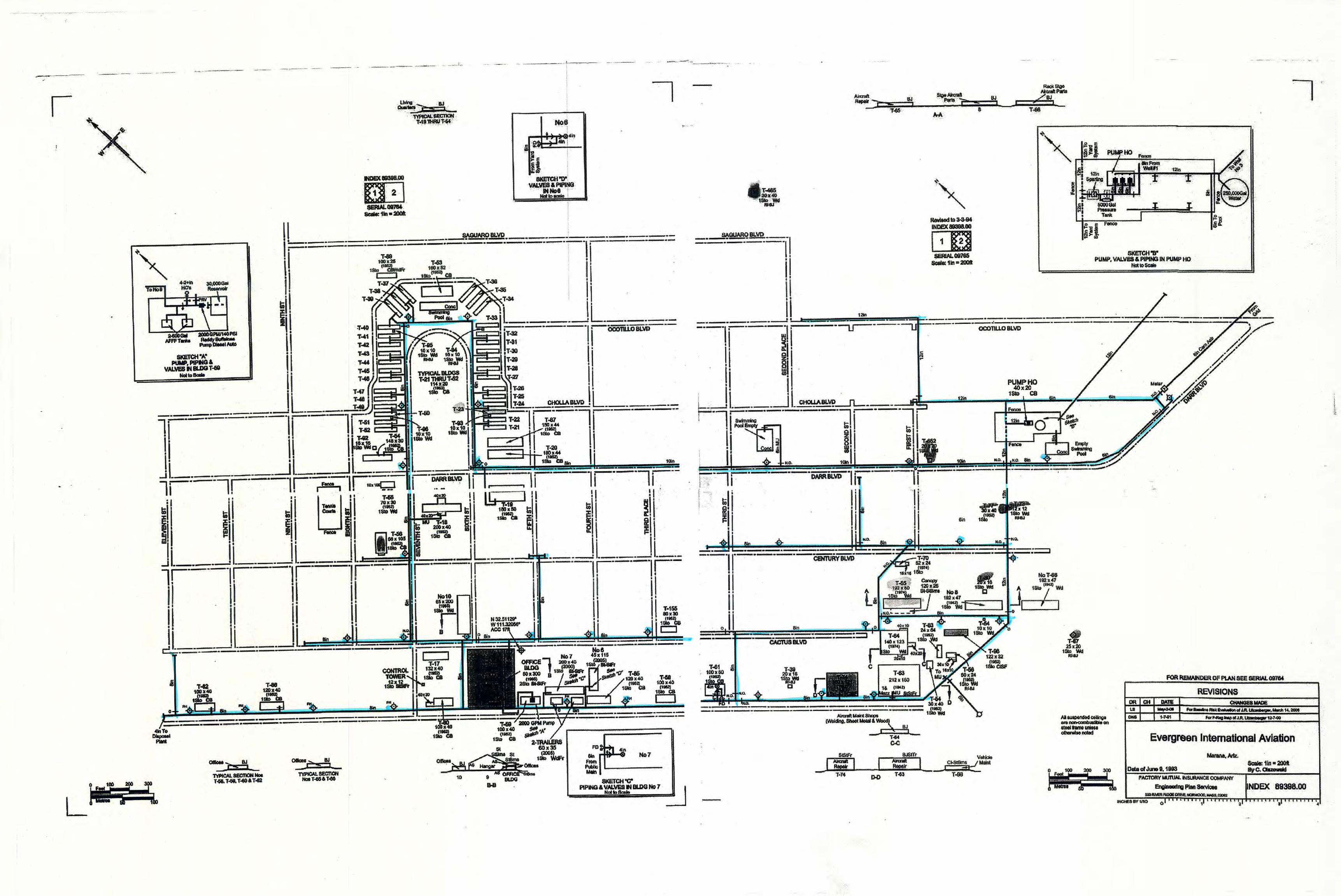
Mapping provided by Marana Aerospace Solutions (MAS) was used to index the existing water and
sewer networks. The list was supplemented with information gathered during a site visit attended by
representatives from Dibble Engineering, Pinal County, and MAS on August 30, 2012. The mapping
provided is included in Appendix A.
A. Water Distribution Network
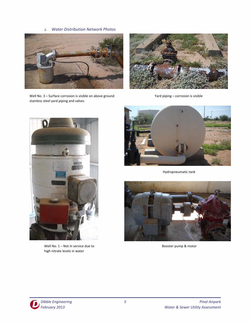
The existing water system, as described by the current tenant’s operating staff and schematic drawings,
generally consists of two (2) active wells, a storage reservoir, three (3) booster pumps, a
hydropneumatic tank and air compressor, a chlorine disinfection system, approximately 23,000 linear
feet of six to twelve‐inch distribution mains, and approximately 35 fire hydrants. Annual and daily
demands of the water network were not available at the time of this assessment and were not
evaluated.
1. Water System Inventory
The distribution network operating pressure as observed during the site visit and as explained by the
Airport operations staff ranges approximately between 30‐50 psi. One well feeds a steel tank reservoir.
Booster pumps draw from the reservoir to a hydropneumatic tank and then to the distribution piping. A
second well that produces non‐potable water connects to the yard piping between the reservoir and the
pump house, but is isolated by a closed gate valve. Table 1 below provides a more precise inventory of
the system.
Table 1 – Water System Inventory
Item Description Year of Installation
Well No. 1
Well #1 produces 750 gpm of non‐potable water that contains
high nitrate levels. ADWR Registration No. 55‐617486.
The pump is a Fairbanks‐Morse vertical turbine, 100 HP, 220/440
Volt, 3 Phase.
1942
Well No. 2 Well #2 was capped in 1992 and is no longer in use.
ADWR Registration No. 55‐617487. 1942
Well No. 3
Well #3 is the primary well that serves the Airport and produces
250 gpm.
ADWR Registration No. 55‐533158.
In approximately 2009 a new pump, motor, and casing liner were
installed. The submersible pump is Simmons manufacture, 460
Volt, 60 Amp.
1992
Booster
Pumps
The 20 HP, 220/440 Volt motors are Fairbanks‐Morse
manufacture. The pumps are American‐Marsh centrifugal pumps,
each rated for 670 gpm at 81 feet of Total Dynamic Head (TDH).
The pumps are set for a minimum run time of 2 minutes.
Unknown (motors)
2002 (pumps)

Dibble Engineering
February 2013
4 Pinal Airpark
Water & Sewer Utility Assessment
Reservoir The 250,000 gallon capacity steel tank reservoir was
manufactured by Brown Tank and Steel, Phoenix, Arizona 1984
Yard Piping
The piping between the reservoir and the pump house and the
between the pump house and the hydropneumatic tank is
welded steel pipe. Original piping is still in use as well as new
piping that was replaced as recently as 1992 with the installation
of Well No.3.
1940’s ‐ 1992
Hydropneumatic
Tank
The steel hydropneumatic tank was manufactured by Adkins
Steel Mfg, is designed for a working pressure up to 125 psi, and
was refurbished in 2002. According to mapping dated October
1962, the original tank had a 5,000 gallon capacity.
1972, 2002
Air Compressor The air compressor for the hydropneumatic tank is a 3HP, belt
drive with Dayton motor. Unknown
Chlorination
System
The chlorination system is a granular calcium hypochlorite feed
system, which operates on a time delay to dose chlorine as water
is pumped to the distribution system.
2002
Distribution
System Piping
The distribution piping is reported to be cast iron. Where line
breaks have occurred, segments have been replaced with ductile
iron pipe.
1940’s
Fire Hydrants
The hydrants at the airport are not of uniform manufacture.
Operations staff indicated that approximately 80% of original
hydrants have been replaced. Some of the original hydrants are
out of service. Dry barrel type hydrant manufacturers include
A.P. Smith Mfg. Co (original), American Flow Control and Clow.
Operations staff indicated that approximately 4 flush type
hydrants are still in use along the flight line.
1940’s – 2000’s
Valves
The distribution system has isolation gate valves throughout the
network.
The check valve at Well No. 1 was replaced 2008.
Check valves at the pump house were replaced in approximately
2002.
1940’s ‐ 2008
Dibble Engineering
February 2013
5 Pinal Airpark
Water & Sewer Utility Assessment
2. Water Distribution Network Photos
Well No. 3 – Surface corrosion is visible on above ground Yard piping – corrosion is visible
stainless steel yard piping and valves
Hydropneumatic tank
Well No. 1 – Not in service due to Booster pump & motor
high nitrate levels in water

Dibble Engineering
February 2013
6 Pinal Airpark
Water & Sewer Utility Assessment
250,000 gallon steel tank reservoir 250,000 gallon steel tank reservoir
Newer hydrant Newer hydrant Original hydrant – out of service
Flush type hydrant Flush type hydrant

Dibble Engineering
February 2013
7 Pinal Airpark
Water & Sewer Utility Assessment
B. Sewer System Network
The existing wastewater system generally consists of a self‐contained stabilization/evaporation basin
system (one lined, combined basin and one unlined dual basin system), approximately 38,000 linear feet
of six to 12‐inch gravity sewers, approximately 40 manholes and approximately 75 sewer cleanouts.
Annual and daily flow rates of the sewer system were not available at the time of this assessment and
were not evaluated.
1. Sewer System Inventory
Table 2 below provides an inventory of the sewer collection and disposal system.
Table 2 – Sewer System Inventory
Item Description Year of
Installation
Sewer Piping
Sewer piping varies from 6” to 12” in diameter and is original. Pipe
material is vitrified clay pipe (VCP), except where polyvinyl chloride pipe
has been used in new construction after the original installation.
1940’s
Sewer Manholes Manholes are brick and mortar construction and are original. 1940’s
Sewer Cleanouts Cleanouts are located throughout the sewer collection system 1940’s
Stabilization
Ponds
One of the stabilization ponds has recently been lined with a high density
polyethylene (HDPE) liner. Additional evaluation of the ponds, including
determining their capacity is not part of this system evaluation.
1940’s –
2000’s
2. Sewer System Photos
Manhole downstream of Bldgs T‐33 &T‐34 Manhole along main line to stabilization ponds
Seventh St & Century Blvd
Dibble Engineering
February 2013
8 Pinal Airpark
Water & Sewer Utility Assessment
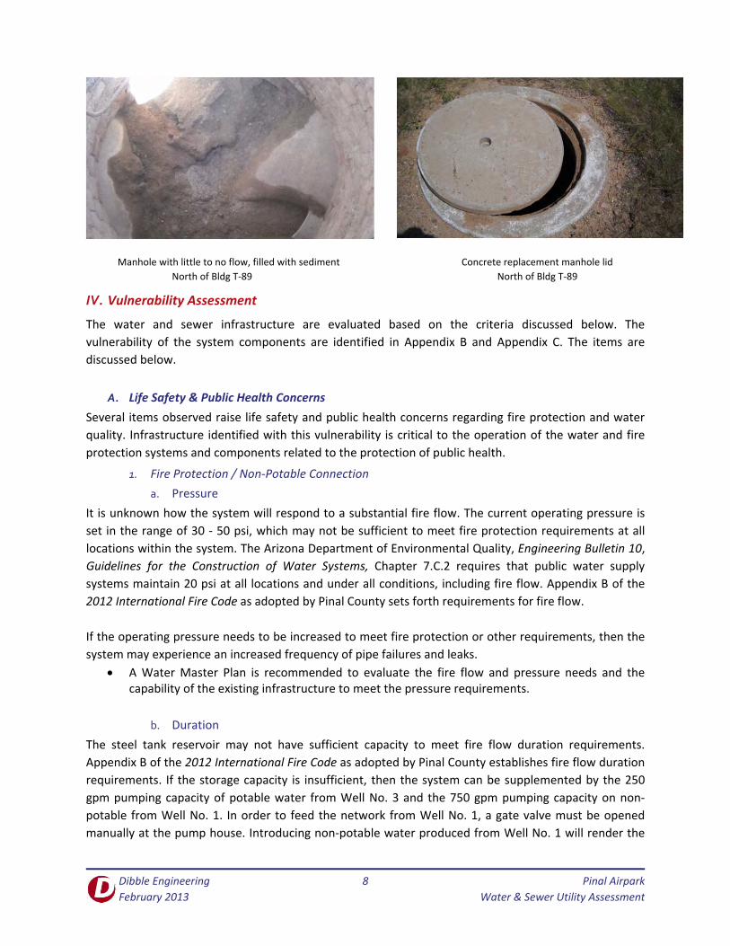
Manhole with little to no flow, filled with sediment Concrete replacement manhole lid
North of Bldg T‐89 North of Bldg T‐89
IV. Vulnerability Assessment
The water and sewer infrastructure are evaluated based on the criteria discussed below. The
vulnerability of the system components are identified in Appendix B and Appendix C. The items are
discussed below.
A. Life Safety & Public Health Concerns
Several items observed raise life safety and public health concerns regarding fire protection and water
quality. Infrastructure identified with this vulnerability is critical to the operation of the water and fire
protection systems and components related to the protection of public health.
1. Fire Protection / Non‐Potable Connection
a. Pressure
It is unknown how the system will respond to a substantial fire flow. The current operating pressure is
set in the range of 30 ‐ 50 psi, which may not be sufficient to meet fire protection requirements at all
locations within the system. The Arizona Department of Environmental Quality, Engineering Bulletin 10,
Guidelines for the Construction of Water Systems, Chapter 7.C.2 requires that public water supply
systems maintain 20 psi at all locations and under all conditions, including fire flow. Appendix B of the
2012 International Fire Code as adopted by Pinal County sets forth requirements for fire flow.
If the operating pressure needs to be increased to meet fire protection or other requirements, then the
system may experience an increased frequency of pipe failures and leaks.
A Water Master Plan is recommended to evaluate the fire flow and pressure needs and the capability of the existing infrastructure to meet the pressure requirements.
b. Duration
The steel tank reservoir may not have sufficient capacity to meet fire flow duration requirements.
Appendix B of the 2012 International Fire Code as adopted by Pinal County establishes fire flow duration
requirements. If the storage capacity is insufficient, then the system can be supplemented by the 250
gpm pumping capacity of potable water from Well No. 3 and the 750 gpm pumping capacity on non‐
potable from Well No. 1. In order to feed the network from Well No. 1, a gate valve must be opened
manually at the pump house. Introducing non‐potable water produced from Well No. 1 will render the

Dibble Engineering
February 2013
9 Pinal Airpark
Water & Sewer Utility Assessment
distribution network non‐potable until the lines are flushed and disinfected and meet Arizona
Department of Environmental Quality (ADEQ) water quality standards.
If the tank storage is insufficient or if well or booster pumps fail, then adequate flow and pressure may
not be achieved at the hydrants.
A Water Master Plan that addresses required fire flow duration and the system’s ability to meet the duration requirement is recommended.
c. Hydrant Spacing
Hydrant type and spacing may not be sufficient to meet current fire protection standards. Appendix C of
the 2012 International Fire Code as adopted by Pinal County establishes fire hydrant spacing
requirements. The existing hydrants in the network are not of uniform manufacture, some of the
hydrants at the Airport are out of service, and most have received minimal maintenance. This makes
spare parts stocking and periodic maintenance more difficult and increases the potential for failure
during adverse operating conditions. If existing hydrants that are still operable do not meet required
hydrant spacing, then adequate fire flow protection may not be available where needed.
Developing a Water Master Plan is recommended to identify hydrant spacing requirements and the system’s compliance or non‐compliance with that spacing.
It is recommended that the Airport adopt uniform standards for hydrants, such as AWWA C502.
2. Wastewater Collection
The existing gravity sewer collection system is operational. Typical sewer pipeline construction of the period utilized practices that may result in significant system leakage. Leaks can occur at separated joints, missing gaskets at joints, and at cracked or broken pipes. Leachate from a leaking sewer system has the potential to eventually contaminate the aquifer and groundwater supply.
A condition assessment of the existing sewer system is recommended to identify locations of leaks and broken pipes.
A Sewer Master Plan is recommended to be developed to ensure pipe sizes, slopes, and cover are sufficient for the needs of the Airport.
B. System Redundancy & Reliability
The system was also evaluated for redundancy and its reliability to meet required demands.
Infrastructure identified with this vulnerability is necessary for the system to continue operations during
failure elsewhere in the system.
1. Water Supply
Currently, the system is supplied by one well that produces potable water, Well No. 3. A second well,
Well No. 1, is available, but produces non‐potable water which, if introduced to the network, would
result in non‐compliance with ADEQ drinking water quality regulations.
A Water Master Plan is recommended that addresses redundancy of the network, which may include a second potable water well that provides a redundant water supply.

Dibble Engineering
February 2013
10 Pinal Airpark
Water & Sewer Utility Assessment
2. Water Storage
The system has one steel tank reservoir. Without demand data or metering, the adequacy of the existing
storage tank to meet diurnal supply and fire flow duration demand requirements is unknown.
A Water Master Plan is recommended that addresses the adequacy of the water storage reservoir to meet current domestic and fire flow demands.
3. Booster Pumping Capacity
Three booster pumps provide for redundant operation if pump failure occurs or if one pump is removed
for maintenance. Capacity for the pumps to meet fire flow pressure requirements is unknown at this
time. As the booster pump system continues to age, obtaining and stocking replacement parts will
become increasingly more difficult. The pump motors are across‐the‐line type which cause more stress
on the pump shaft than soft‐starter type pump motors that are available today.
A Water Master Plan is recommended to determine booster pumping capacity needs.
A new booster pump station with components that meet current standards is recommended.
4. Water Distribution System Integrity
Sufficient looping and isolation ability may be present to allow isolation in the event of main breaks.
A Water Master Plan is recommended to determine the capability of the existing network to deliver required domestic and fire flow demands. Frequency of pipe failures in the existing system may increase as the operating pressure of the system is increased.
5. Sewer System
Gravity sewers typically do not have redundancy, and a maintenance program should be developed and
implemented to ensure proper operation. A condition assessment is recommended to determine the
reliability of the sewer network, that the system is free of clogs, debris and can convey wastewater flow
without hindrance.
C. Maintenance / Rehabilitation / Replacement
In order to provide a reliable water system and sewer system, new and existing infrastructure must be
maintained. Much of the existing water and sewer infrastructure has met or exceeded its design life and
should be replaced. Components such as the well, storage tank, and booster pump station are critical to
the operation of the water system and should be maintained and reliable. Components such as hydrants
and piping can be replaced more easily in the event that a failure occurs or a pipe breaks. An operations
and maintenance program should be prepared that outlines mechanical components to be exercised,
lines to be flushed, and pipes to be replaced to assist in providing a reliable network.
A standard maintenance, condition assessment, and rehabilitation/replacement program is recommended for all infrastructure. The program should include:
o Periodic condition assessment o Operating equipment efficiency evaluation o Regular and periodic maintenance program o Standardized record keeping procedures, including operator checklists

Dibble Engineering
February 2013
11 Pinal Airpark
Water & Sewer Utility Assessment
D. Capacity for Expansion
Consideration should be given to the Airport’s plans for growth and expansion. If portions of the existing
network require replacement, then it can be cost effective to perform system upgrades for capacity at
the time of repairs and replacements. Knowing what the future plans for growth are for the Airport is
needed to plan how to meet the future needs of the facility.
A Water Master Plan is recommended that addresses the capacity of or expansions to the existing system to meet the future demands and needs of the Airport.
A Sewer Master Plan is recommended that addresses the capacity of or expansions to the existing system to meet the future demands and needs of the Airport.
V. Recommendations
This report indexes the existing infrastructure and assesses the risk of not taking action on various
components of the network. Recommendations have been developed based on the vulnerability of the
systems including consideration of potential life safety concerns. The recommendations have been given
priority ratings of recommended actions that and can be accomplished together.
Note that the water and sewer systems are currently in operation and do not appear to have any
immediate catastrophic vulnerabilities as pumps have been replaced and are maintained, piping has
been replaced as needed, sewer manholes that are in use are not missing bricks and have mortar still in
place. In order to avoid catastrophic failures in the system, it is recommended that the County not delay
further assessment of the infrastructure and make upgrades based on the priority list below.
Table 3 on the following page summarizes the proposed recommendations with conceptual costs for
each priority group. The conceptual capital cost of each recommendation is itemized in Appendix C.
Priority ratings are defined as follows:
A = Immediate
B = Short Term
C = Longer Term

Dibble Engineering
February 2013
12 Pinal Airpark
Water & Sewer Utility Assessment
Table 3 – Recommendations
Recommendation
No. Priority Description
Capital
Cost
1 A
Prepare Water Master Plan of Airport with hydraulic
modeling of the existing infrastructure and future expansion
of water distribution network, including fire protection
needs. Valve rims and top of nut elevations should be
surveyed to develop an accurate map of existing
infrastructure.
As part of the modeling effort, perform hydrant flow tests
to determine the capacity of the network and if the existing
infrastructure meets required fire flow requirements.
Leakage tests should also be performed to identify which
portions of the network experience excessive leaking.
The master plan should also include preparation of
standards to be adopted by the Airpark for future repairs,
replacements, and other improvements.
The water distribution network should comply with ADEQ
Bulletin 10 and the 2012 International Fire Code.
$200k
2 B
Well Redundancy – Provide a second well that produces
potable water or modify or treat the existing Well No. 1 to
produce potable water, American Water Works Association
(AWWA) A100.
$300k
3 B
Booster Pump Facility – The booster pump facility and
appurtenances, including pumps, motors, valves, piping,
hydropneumatic tank, chlorination system have exceeded a
reasonable design life for a maintained system. Since the
facility is operational, the need for replacement is not
immediate, but should be planned for in the near future.
The new pump station should meet the appropriate AWWA
Standards.
$1.0M
4 B
Hydrant Replacement Program – The Airport has several
types of hydrants throughout the distribution network,
several of which are no longer operational. A hydrant
replacement program should be developed to bring the
spacing and type of functional hydrants into compliance
with the Water Master Plan. Dry barrel hydrants should
comply with AWWA C502.
$300k

Dibble Engineering
February 2013
13 Pinal Airpark
Water & Sewer Utility Assessment
5 C
Valve & Water Line Replacement Program – Valves that are
no longer operational should be replaced to bring the
network into compliance with the Water Master Plan so
that the isolation needs of the Airport are met.
As the aging water lines in the distribution network fail, a
plan should be developed to replace the infrastructure prior
to failure. Planning water line shutdowns for replacement is
typically less disruptive and less costly than repairing water
line breaks as they occur.
For example, the County may implement a replacement
program that replaces 10% of the existing infrastructure
each year for 10 years until. Alternatively, the County may
desire to include water main replacement and upsizing
based on the future needs described in the Water Master
Plan.
$3M
(may be
broken into a
multi‐year
program)
6 C
Expansion / Future Growth – Additional water distribution
should be constructed to meet the future expansion of the
Airpark. The expansion of the Airpark water distribution
network should be outlined in the Water Master Plan and
be based on the Airport Master Plan.
Infrastructure needed for expansion may include:
Increasing distribution system capability
Additional booster pumping capacity and
associated infrastructure (disinfection,
hydropneumatic tank, etc.)
Additional storage capacity
Additional supply capacity (new wells)
TBD
7 C
Tank Condition Assessment – Airport staff have indicated
that the steel storage tank has not been inspected or leak
tested since installation. The tank should have a condition
assessment performed, including the condition of the
coating and a leak test in accordance with AWWA Manual
M42.
An operation and maintenance program should be
implemented in accordance with AWWA M42.
$60k
8 A
Valve Exercise & Hydrant Flushing Program – An operation
and maintenance program for valve exercising and hydrant
flushing should be implemented in accordance with
manufacturer recommendations, AWWA C502, and AWWA
C509.
$10k/year

Dibble Engineering
February 2013
14 Pinal Airpark
Water & Sewer Utility Assessment
9 A
Sewer Condition Assessment –
The existing sewer manholes and cleanouts should
be surveyed with rim and invert elevations
identified to develop an accurate map of existing
infrastructure.
The existing sewer network of pipes and manholes
should be inspected and assessed using Nassco’s
Pipeline Assessment and Certification Program
(PACP).
Perform a hydraulic analysis to determine the
capacity of the existing sewer network.
$200k
10 A
Sewer Master Plan – In conjunction with the Water Master
Plan, a Sewer Master Plan should be prepared to ensure
pipe sizes, slopes, and cover are sufficient for current and
future needs of the Airport. Existing and future sewer
construction should comply with Arizona Administrative
Code (AAC), Title 18, Chapter 9.
The collection and disposal system should be confirmed for
compliance with the AAC, Title 18, Chapter 9, Articles 1 and
3.
$100k
11 B
Sewer Repair / Maintenance / Abandonment –
A program should be prepared to address the
recommendations from the Sewer Condition Assessment
and the Sewer Master Plan. The County may desire to
allocate funds to perform a percentage of the total
recommended work each year similar to the Valve & Water
Line Replacement Program.
Repair & replace sewer segments and manholes as
needed based on Sewer Condition Assessment,
including pipe that is out of grade.
Remove debris and accumulated solids from
manholes and sewers as observed during Sewer
Condition Assessment.
Abandon existing sewers that are not in use and
are needed per the Sewer Master Plan.
TBD
The next steps the County should take to ensure safe and reliable water and sewer systems are to
prepare Water and Sewer Master Plans. Understanding the current capabilities and capacities of the
water and sewer systems is needed to properly prepare master plan and to confirm that the current
facility and fire protection requirements can be met by the existing infrastructure.

Dibble Engineering
February 2013
Pinal Airpark
Water & Sewer Utility Assessment
APPENDIX A
Utility Mapping, As‐Builts, Other Utility Data


Dibble Engineering
February 2013
Pinal Airpark
Water & Sewer Utility Assessment
APPENDIX B
Inventory of Water Infrastructure & Vulnerability Assessment


Life Safety /
Public
Health
Redundancy /
Reliability
Maintenance /
Capacity for
Expansion
Not in Use
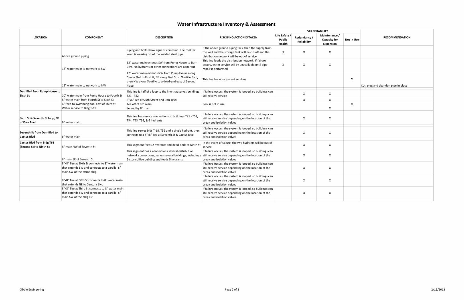
Ocotillo Blvd & Darr Blvd 6" water main 6" main to the east (ACP) X Cut, plug and abandon pipe in place
Water meter Not in use X Remove meter & vault
6" water main from intersection NW to Pump
House
Tee after meter splits flow to network and to pump
The Airpark distribution network is be dependent on
the well water supply. Note that this portion of the
network does not have any apparent services.
X
Cut, plug and abandon pipe in place
6" & 8" water main from intersection west and
NW to SW side of Pump House and
12"x12"x10"x8" cross
Feed to former housing and meter, includes a single fire
hydrantX
Cut, plug and abandon pipe in place at cross
Well Pump (Primary) Well #2
Well #2 was capped in 1992 and is no longer in use X X Confirm well abandonment is recorded with ADWR
and is compliant with environmental standards
Pump (Well #3)
460 V, 60 A, submersible pump ‐ new pump, motor and
liner installed 2009, yields 250 gpm
If well pump or appurtenances fail, then Airpark
distribution network will be without a potable water
supply
X X X Confirm well is sufficient to meet demands of network.
Consider drilling secondary well that is potable.
Above ground piping piping and bolts show corrosion X X X Remove & replace
12" below ground piping piping feeds 250,000 gallon storage tank X X X Remove & replace
Pump House Well #1
Well #1 is backup to the network, the water contains high
nitrates and is therefore not potable. The Well #1 piping
is connected to the distribution network at a tee outside
of the booster pump house. Separation is provided by an
in line gate valve set at grade at the tee.
In the event Well #3 is disabled or insufficient to
supply fire flow demands, Well #1 may need to be
used.
X X
A separate well or treatment to this well that meets
potable water requirements should be considered as a
redundant source. An isolation and flushing plan
should be developed in the event non‐potable water
enters the distribution network. The separation by
gate valve should be evaluated for cross‐
contamination compliance.
Pump (Well #1) Yields 750 gpm X
Pump House StructureThe structure is original with some repairs/modifications The building may not meet current building codes. X X
Remove & replace the pump house
Booster pumps
The original pumps were replaced in approximately 2002,
the center pump was rebuilt in 2012.X X X
Pump motors
The original 20 HP pump motors are in use and are
rebuilt as needed
The pumps are not equipped with soft start motors,
which creates a potentially unsafe condition with
pumps starting at full torque.
X X X
Replace pump motors with soft start motors
250,000 gallon tank
The tank was installed in 1984. The tank has not been
leak tested, recoated, or inspected since installation.
If tank fails or is taken out of service for maintenance,
then the Airpark distribution network will dependent
on the well pump for water supply
X X X
5000 gallon hydropneumatic tank
A refurbished tank was installed in approximately 2002.
The tank has an air release valve that is not in use.
The hydropneumatic tank allows the booster pumps
to engage for a minimum duration. In the event the
tank fails, the pumps will engage to maintain system
pressure. Without a hydropneumatic tank, the pump
will operate on‐demand resulting in short‐cycling the
pump which, can cause excessive wear on the pumps
and motors.
X X X
Chlorination injection system & air compressor Installed 2002 X X X
Electrical equipment
Electrical enclosures, switches and circuit breakers
appear to be original with newer contacts and startersX X X
An electrical engineer should evaluate the condition of
the electrical gear and wiring to ensure operations
meet current code requirements.
Valves Check valves have been replaced in past 10 years, X X X
Water Infrastructure Inventory & AssessmentVULNERABILITY
LOCATION COMPONENT DESCRIPTION RISK IF NO ACTION IS TAKEN RECOMMENDATION
Dibble Engineering Page 1 of 3 2/13/2013
Life Safety /
Public
Health
Redundancy /
Reliability
Maintenance /
Capacity for
Expansion
Not in Use
Water Infrastructure Inventory & AssessmentVULNERABILITY
LOCATION COMPONENT DESCRIPTION RISK IF NO ACTION IS TAKEN RECOMMENDATION
Above ground piping
Piping and bolts show signs of corrosion. The coal tar
wrap is wearing off of the welded steel pipe.
If the above ground piping fails, then the supply from
the well and the storage tank will be cut off and the
distribution network will be out of service
X X X
12" water main to network to SW
12" water main extends SW from Pump House to Darr
Blvd. No hydrants or other connections are apparent
This line feeds the distribution network. If failure
occurs, water service will by unavailable until pipe
repair is performed
X X X
12" water main to network to NW
12" water main extends NW from Pump House along
Cholla Blvd to First St, NE along First St to Ocotillo Blvd,
then NW along Ocotillo to a dead‐end east of Second
Place
This line has no apparent services X
Cut, plug and abandon pipe in place
Darr Blvd from Pump House to
Sixth St 10" water main from Pump House to Fourth St
This line is half of a loop to the line that serves buildings
T21 ‐ T52
If failure occurs, the system is looped, so buildings can
still receive serviceX X
8" water main from Fourth St to Sixth St 8"x6" Tee at Sixth Street and Darr Blvd X X
6" feed to swimming pool east of Third St Tee off of 10" main Pool is not in use X
Water service to Bldg T‐19 Served by 8" main X
Sixth St & Seventh St loop, NE
of Darr Blvd 6" water main
This line has service connections to buildings T21 ‐ T52,
T54, T93, T96, & 6 hydrants
If failure occurs, the system is looped, so buildings can
still receive service depending on the location of the
break and isolation valves
X X
Seventh St from Darr Blvd to
Cactus Blvd 6" water main
This line serves Blds T‐18, T56 and a single hydrant, then
connects to a 8"x6" Tee at Seventh St & Cactus Blvd
If failure occurs, the system is looped, so buildings can
still receive service depending on the location of the
break and isolation valves
X X
Cactus Blvd from Bldg T61
(Second St) to Ninth St 8" main NW of Seventh StThis segment feeds 2 hydrants and dead‐ends at Ninth St
In the event of failure, the two hydrants will be out of
serviceX X
8" main SE of Seventh St
This segment has 2 connections several distribution
network connections, serves several buildings, including a
2‐story office building and feeds 5 hydrants
If failure occurs, the system is looped, so buildings can
still receive service depending on the location of the
break and isolation valves
X X
8"x8" Tee at Sixth St connects to 8" water main
that extends SW and connects to a parallel 8"
main SW of the office bldg
If failure occurs, the system is looped, so buildings can
still receive service depending on the location of the
break and isolation valves
X X
8"x8" Tee at Fifth St connects to 8" water main
that extends NE to Century Blvd
If failure occurs, the system is looped, so buildings can
still receive service depending on the location of the
break and isolation valves
X X
8"x8" Tee at Third St connects to 8" water main
that extends SW and connects to a parallel 8"
main SW of the bldg T61
If failure occurs, the system is looped, so buildings can
still receive service depending on the location of the
break and isolation valves
X X
Dibble Engineering Page 2 of 3 2/13/2013

Life Safety /
Public
Health
Redundancy /
Reliability
Maintenance /
Capacity for
Expansion
Not in Use
Water Infrastructure Inventory & AssessmentVULNERABILITY
LOCATION COMPONENT DESCRIPTION RISK IF NO ACTION IS TAKEN RECOMMENDATION
Cactus Blvd from Bldg T61
(Second St) to Tee between
Bldgs T80 and T68 8" water main
This segment serves several buildings, feeds 3 hydrants
and is part of a loop.
If failure occurs, the system is looped, so buildings can
still receive service depending on the location of the
break and isolation valves
X X
Cactus Blvd from Tee between
Bldgs T80 and T68 to Century
Blvd & First St 6" water main
This line extend NE, then east from the 8"x6" Tee at Bldg
T61, serves Bldg T70, and connects to and 8" water main
in Century Blvd
In the event of failure, Bldg T70 may be without
service depending on isolation valve locations and the
break location
X X
Pump House to Tee between
Bldgs T80 and T68 12" water main (LINE A)
This line connects to the 8" water main in Century Blvd at
a 12"x8" Tee, connects to the 12"x12"x10"x8' cross at
Pump House, and serves a single hydrant at Century Blvd
This line feeds the southwestern portion of the
distribution network loop. If failure occurs, water must
serve the Airpark via the water main in Darr Blvd
X X
Century Blvd from LINE A to
Third St 8" water main
This segment connects to the 12" water main from Pump
House (LINE A), the 6" water main at First St, and a dead‐
end line on Second St from Century Blvd to Darr Blvd.
The line serves 4 hydrants and dead‐ends NW of Third St.
In the event of failure NW of First St, the hydrants will
be out of service. The remainder of the line is looped.X X
Tee between Bldgs T80 and
T68 at Cactus Blvd to Eleventh
St, NW of Bldg T62 8" water main
This segment serves numerous buildings, serves 10
hydrants, and connects to the Distribution network at an
8"x8" Tee at Third St and an 8"x8" Tee at Sixth St. An 8"
dead‐end line extends NE at Eleventh St to Cactus Blvd
and a 4" ine continues past Eleventh Street to the
Disposal Plant
If failure occurs, the system is looped, so buildings can
still receive service depending on the location of the
break and isolation valves. If failure occurs NW of Sixth
St, then buildings in that area and the 4" Disposal Plant
line will be out of service.
X X
Dibble Engineering Page 3 of 3 2/13/2013

Dibble Engineering
February 2013
Pinal Airpark
Water & Sewer Utility Assessment
APPENDIX C
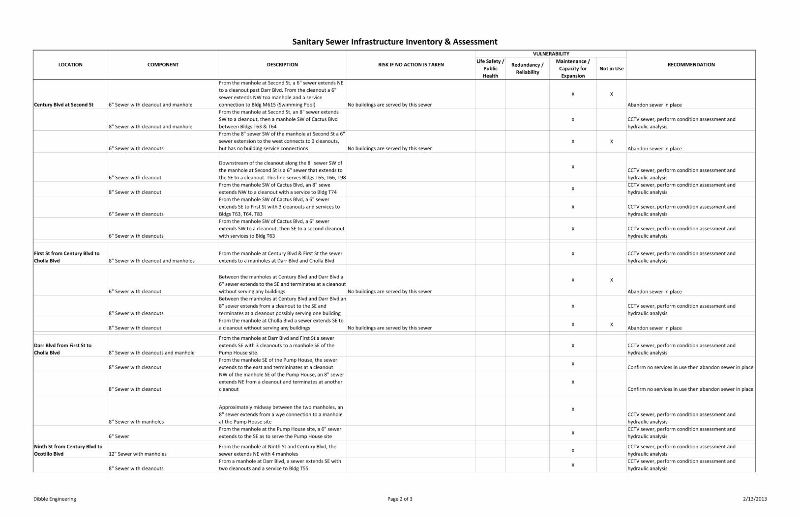
Inventory of Sewer Infrastructure & Vulnerability Assessment


Life Safety /
Public
Health
Redundancy /
Reliability
Maintenance /
Capacity for
Expansion
Not in Use
Stabilization Ponds to Eleventh
St & Century Blvd 12" Sewer
Sewer outfall to evaporation pond ‐ no manholes were
visible along this segment
Sewer leakage may have adverse environmental
impacts, clogged, broken, or out of grade sewers may
impede flow ‐ Typical all components
X XCCTV sewer, perform condition assessment and
hydraulic analysis
Century Blvd ‐ Eleventh St to
Fifth St 12" Sewer with manholes
Manholes located at Eleventh St, Tenth St, Ninth St,
Eigth St, Seventh St, Fifth StX
CCTV sewer, perform condition assessment and
hydraulic analysis
8" Sewer with cleanouts
Sewer extends to NW along Tenth St and serves Bldg
T61, T62 & T86X
CCTV sewer, perform condition assessment and
hydraulic analysis
8" Sewer with cleanout
Sewer extends SW along Ninth St and stubs to a
cleanout ‐ no buildings are served No buildings are served by this sewerX X
Abandon sewer in place
8" Sewer with cleanouts
Sewer extends to NW along Seventh St to Cactus St and
serves T17 & T60; also has a stub and cleanout along
Cactus to NW, but no buildings are served
XCCTV sewer, perform condition assessment and
hydraulic analysis
8" Sewer & 6" Sewer with cleanouts
From the manhole at Century Blvd and Fifth St, an 8"
sewer extends SW along Fifth St to a cleanout at Cactus
Blvd. From the cleanout, a 6" line extends south to
another cleanout and services to Bldg T59 & the Office
Bldg
X
CCTV sewer, perform condition assessment and
hydraulic analysis
Century Blvd at SixthSt 8" Sewer with manholes
Sewer extends from manhole at Century & Sixth St NE
to a manhole at Darr Blvd. This line has one cleanout
and has a service connection to Bldg T18
XCCTV sewer, perform condition assessment and
hydraulic analysis
6" Sewer with cleanouts
From the manhole at Darr Blvd & Sixth St, a 6" sewer
extends along Darr Blvd to Fifth St, and serves several
buildings in the area. The lines have 7 cleanouts and
serve Bldgs T19, T20 , T87
X
CCTV sewer, perform condition assessment and
hydraulic analysis
Century Blvd from Fifth St to
Third Pl 10" Sewer with manholes Manholes located at Fourth St and Third PlX
CCTV sewer, perform condition assessment and
hydraulic analysis
Century Blvd at Third Pl 6" Sewer with cleanouts
From the manhole at Third Pl, the sewer extends NW to
Cactus Blvd to a cleanout, then west to a dead‐end
cleanout and south to a cleanout and service to Bldg
T58
XCCTV sewer, perform condition assessment and
hydraulic analysis
8" Sewer with cleanouts
From the manhole at Third Pl, the sewer extends NE to
Darr Blvd to cleanout. No buildings are served by this sewerX X
Abandon sewer in place
6" Sewer with cleanouts
From the 8" cleanout at Darr Blvd, the sewer has a wye
connection and reduces to two 6" sewers. One 6" sewer
continues to the NE to a cleanout, then NW to another
cleanout. The second 6" line extends SW past Third St
and ends at a cleanout without serving any buildings. No buildings are served by this sewer
X X
Abandon sewer in place
Century Blvd from Third Pl to
First St 8" Sewer with cleanouts and manholes
From the manhole at Third Pl, the sewer extends SE
with 3 cleanouts to a manhole at Second St. SW of the
third cleanout is a stub with a cleanout that serves no
buildings.
XCCTV sewer, perform condition assessment and
hydraulic analysis
8" Sewer with manholes
From the manhole at Second St, the sewer extends to a
manhole at First StX
CCTV sewer, perform condition assessment and
hydraulic analysis
Sanitary Sewer Infrastructure Inventory & Assessment
LOCATION COMPONENT DESCRIPTION RISK IF NO ACTION IS TAKEN
VULNERABILITY
RECOMMENDATION
Dibble Engineering Page 1 of 3 2/13/2013
Life Safety /
Public
Health
Redundancy /
Reliability
Maintenance /
Capacity for
Expansion
Not in Use
Sanitary Sewer Infrastructure Inventory & Assessment
LOCATION COMPONENT DESCRIPTION RISK IF NO ACTION IS TAKEN
VULNERABILITY
RECOMMENDATION
Century Blvd at Second St 6" Sewer with cleanout and manhole
From the manhole at Second St, a 6" sewer extends NE
to a cleanout past Darr Blvd. From the cleanout a 6"
sewer extends NW toa manhole and a service
connection to Bldg M615 (Swimming Pool) No buildings are served by this sewer
X X
Abandon sewer in place
8" Sewer with cleanout and manhole
From the manhole at Second St, an 8" sewer extends
SW to a cleanout, then a manhole SW of Cactus Blvd
between Bldgs T63 & T64
X CCTV sewer, perform condition assessment and
hydraulic analysis
6" Sewer with cleanouts
From the 8" sewer SW of the manhole at Second St a 6"
sewer extension to the west connects to 3 cleanouts,
but has no building service connections No buildings are served by this sewer
X X
Abandon sewer in place
6" Sewer with cleanout
Downstream of the cleanout along the 8" sewer SW of
the manhole at Second St is a 6" sewer that extends to
the SE to a cleanout. This line serves Bldgs T65, T66, T98
XCCTV sewer, perform condition assessment and
hydraulic analysis
8" Sewer with cleanout
From the manhole SW of Cactus Blvd, an 8" sewe
extends NW to a cleanout with a service to Bldg T74X
CCTV sewer, perform condition assessment and
hydraulic analysis
6" Sewer with cleanouts
From the manhole SW of Cactus Blvd, a 6" sewer
extends SE to First St with 3 cleanouts and services to
Bldgs T63, T64, T83
X CCTV sewer, perform condition assessment and
hydraulic analysis
6" Sewer with cleanouts
From the manhole SW of Cactus Blvd, a 6" sewer
extends SW to a cleanout, then SE to a second cleanout
with services to Bldg T63
X CCTV sewer, perform condition assessment and
hydraulic analysis
First St from Century Blvd to
Cholla Blvd 8" Sewer with cleanout and manholes
From the manhole at Century Blvd & First St the sewer
extends to a manholes at Darr Blvd and Cholla Blvd
X CCTV sewer, perform condition assessment and
hydraulic analysis
6" Sewer with cleanout
Between the manholes at Century Blvd and Darr Blvd a
6" sewer extends to the SE and terminates at a cleanout
without serving any buildings No buildings are served by this sewer
X X
Abandon sewer in place
8" Sewer with cleanouts
Between the manholes at Century Blvd and Darr Blvd an
8" sewer extends from a cleanout to the SE and
terminates at a cleanout possibly serving one building
X CCTV sewer, perform condition assessment and
hydraulic analysis
8" Sewer with cleanout
From the manhole at Cholla Blvd a sewer extends SE to
a cleanout without serving any buildings No buildings are served by this sewerX X
Abandon sewer in place
Darr Blvd from First St to
Cholla Blvd 8" Sewer with cleanouts and manhole
From the manhole at Darr Blvd and First St a sewer
extends SE with 3 cleanouts to a manhole SE of the
Pump House site.
X CCTV sewer, perform condition assessment and
hydraulic analysis
8" Sewer with cleanout
From the manhole SE of the Pump House, the sewer
extends to the east and termininates at a cleanoutX
Confirm no services in use then abandon sewer in place
8" Sewer with cleanout
NW of the manhole SE of the Pump House, an 8" sewer
extends NE from a cleanout and terminates at another
cleanout
X
Confirm no services in use then abandon sewer in place
8" Sewer with manholes
Approximately midway between the two manholes, an
8" sewer extends from a wye connection to a manhole
at the Pump House site
XCCTV sewer, perform condition assessment and
hydraulic analysis
6" Sewer
From the manhole at the Pump House site, a 6" sewer
extends to the SE as to serve the Pump House siteX
CCTV sewer, perform condition assessment and
hydraulic analysis
Ninth St from Century Blvd to
Ocotillo Blvd 12" Sewer with manholes
From the manhole at Ninth St and Century Blvd, the
sewer extends NE with 4 manholesX
CCTV sewer, perform condition assessment and
hydraulic analysis
8" Sewer with cleanouts
From a manhole at Darr Blvd, a sewer extends SE with
two cleanouts and a service to Bldg T55X
CCTV sewer, perform condition assessment and
hydraulic analysis
Dibble Engineering Page 2 of 3 2/13/2013

Life Safety /
Public
Health
Redundancy /
Reliability
Maintenance /
Capacity for
Expansion
Not in Use
Sanitary Sewer Infrastructure Inventory & Assessment
LOCATION COMPONENT DESCRIPTION RISK IF NO ACTION IS TAKEN
VULNERABILITY
RECOMMENDATION
6" Sewer with cleanouts
From a manhole NW of Cholla Blvd and Ninth St, a
sewer extends SE with two cleanouts and services to
Bldgs T51, T52, T54
X CCTV sewer, perform condition assessment and
hydraulic analysis
Ninth St from Ocotillo Blvd
toNE 10" Sewer with cleanout and manhole
From the manhole at Ocotillo, the sewer extends NE
past Saguaro Blvd to a manhole No buildings are served by this sewerX X
Abandon sewer in place
8" Sewer with cleanouts and manholes
From the manhole on Ninth St, NE of Saguaro Blvd, the
sewer extends SE and E with 4 manholes and 8
cleanouts with no service connections No buildings are served by this sewer
X X
Abandon sewer in place
Ocotillo Blvd from Ninth St to
Second St 10" Sewer with manholes
The sewer extends from the manhole at Ninth St to the
SE with 7 manholesX
CCTV sewer, perform condition assessment and
hydraulic analysis
6" Sewer with cleanout
From the manhole NW of the horseshoe of buildings,
the sewer extends SW to a cleanout and serves Bldgs
T41 ‐ T50
X CCTV sewer, perform condition assessment and
hydraulic analysis
6" & 8" Sewer with manhole and cleanouts
From the manhole NW of the horseshoe of buildings,
the sewer extends NE to a manhole. From the NE
manhole a 6" sewer extends SE to a cleanout and serves
Bldg T89. From the NE manhole an 8" sewer extends NE
to a cleanout and then extends SE as a 6" sewer to a
cleanout with no service connections
X
CCTV sewer, perform condition assessment and
hydraulic analysis
6" Sewer with cleanout
From a manhole within the horseshoe at Sixth St, a
sewer extends NE to a cleanout and provides service to
Bldgs T33, T34, T35, T36, T53
XCCTV sewer, perform condition assessment and
hydraulic analysis
6" Sewer with cleanouts
From the SE corner of Bldg T33, a sewer extends SW
with 3 cleanouts and services to Bldgs T21 ‐ T32X
CCTV sewer, perform condition assessment and
hydraulic analysis
6" Sewer with cleanout
From a manhole SE of the horseshoe, a sewer extends
SW to a cleanout with no service connections No buildings are served by this sewerX X
Abandon sewer in place
6" & 8" Sewer with manholes and cleanouts
From a manhole at Third Pl, an 8"s ewer extends NE
and SE with manholes and cleanouts with no active
service connections No buildings are served by this sewer
X X
Abandon sewer in place
6" with cleanout
From SE of a manhole at Second Pl, a sewer extends NE
to a cleanout with no service connections No buildings are served by this sewerX X
Abandon sewer in place
6" with cleanout
From a manhole at Second St, a sewer extends NE to a
cleanout with no service connections No buildings are served by this sewerX X
Abandon sewer in place
Dibble Engineering Page 3 of 3 2/13/2013

Dibble Engineering
February 2013
Pinal Airpark
Water & Sewer Utility Assessment
APPENDIX D
Engineer’s Opinion of Probable Capital Cost

ENGINEER'S OPINION OF PROBABLE CONSTRUCTION COST
Project Name: Pinal Airpark Water & Sewer Utility Assessment Date: 2/13/2013
Project Number: 101234.01 Dibble Project No.: 101207.02
Recommendation: 1 ‐ Water Master Plan Prepared By: K. Faucett
Item No. Item Description Unit Qty Unit Price Extended Total
1 Hydrant Flow Testing LS 1 4,000.00$ 4,000.00$
2 Leakage Testing LS 1 20,000.00$ 20,000.00$
3 Survey & Mapping of Infrastructure LS 1 30,000.00$ 30,000.00$
4 Existing Hydraulic Model LS 1 20,000.00$ 20,000.00$
5 Future Hydraulic Model LS 1 40,000.00$ 40,000.00$
6 Report / Master Plan LS 1 20,000.00$ 20,000.00$
‐$ ‐$
‐$ ‐$
‐$ ‐$
‐$ ‐$
‐$ ‐$
‐$ ‐$
‐$ ‐$
‐$ ‐$
‐$ ‐$
‐$ ‐$
‐$ ‐$
‐$ ‐$
‐$ ‐$
‐$ ‐$
‐$ ‐$
‐$ ‐$
‐$ ‐$
‐$ ‐$
‐$ ‐$
‐$ ‐$
‐$ ‐$
‐$ ‐$
‐$ ‐$
‐$ ‐$
‐$ ‐$
‐$ ‐$
‐$ ‐$
‐$ ‐$
‐$ ‐$
‐$ ‐$
Subtotal 134,000.00$
Contingency 50% 67,000.00$
TOTAL 201,000.00$
Page 1 of 1

ENGINEER'S OPINION OF PROBABLE CONSTRUCTION COST
Project Name: Pinal Airpark Water & Sewer Utility Assessment Date: 2/13/2013
Project Number: 101234.01 Dibble Project No.: 101207.02
Recommendation: 2 ‐ Well Redundancy Prepared By: K. Faucett
Item No. Item Description Unit Qty Unit Price Extended Total
1 Well Drilling & Casing LF 1500 100.00$ 150,000.00$
2 Well Pump & Motor EA 1 50,000.00$ 50,000.00$
‐$ ‐$
‐$ ‐$
‐$ ‐$
‐$ ‐$
‐$ ‐$
‐$ ‐$
‐$ ‐$
‐$ ‐$
‐$ ‐$
‐$ ‐$
‐$ ‐$
‐$ ‐$
‐$ ‐$
‐$ ‐$
‐$ ‐$
‐$ ‐$
‐$ ‐$
‐$ ‐$
‐$ ‐$
‐$ ‐$
‐$ ‐$
‐$ ‐$
‐$ ‐$
‐$ ‐$
‐$ ‐$
‐$ ‐$
‐$ ‐$
‐$ ‐$
‐$ ‐$
‐$ ‐$
‐$ ‐$
‐$ ‐$
‐$ ‐$
‐$ ‐$
Subtotal 200,000.00$
Contingency 50% 100,000.00$
TOTAL 300,000.00$
Page 1 of 1

ENGINEER'S OPINION OF PROBABLE CONSTRUCTION COST
Project Name: Pinal Airpark Water & Sewer Utility Assessment Date: 2/13/2013
Project Number: 101234.01 Dibble Project No.: 101207.02
Recommendation: 3 ‐ Booster Pump Facility Prepared By: K. Faucett
Item No. Item Description Unit Qty Unit Price Extended Total
1 Demolition of Existing Facility LS 1 28,000.00$ 28,000.00$
2 Yard Piping LF 200 150.00$ 30,000.00$
3 Booster Pumps & Motors EA 3 120,000.00$ 360,000.00$
4 Hydropneumatic Tank & Compressor EA 1 100,000.00$ 100,000.00$
5 Isolation & Check Valves ‐ 12" EA 6 7,000.00$ 42,000.00$
6 Pump House Structure EA 1 100,000.00$ 100,000.00$
7 Disinfection System EA 1 6,500.00$ 6,500.00$
‐$ ‐$
‐$ ‐$
‐$ ‐$
‐$ ‐$
‐$ ‐$
‐$ ‐$
‐$ ‐$
‐$ ‐$
‐$ ‐$
‐$ ‐$
‐$ ‐$
‐$ ‐$
‐$ ‐$
‐$ ‐$
‐$ ‐$
‐$ ‐$
‐$ ‐$
‐$ ‐$
‐$ ‐$
‐$ ‐$
‐$ ‐$
‐$ ‐$
‐$ ‐$
‐$ ‐$
‐$ ‐$
‐$ ‐$
‐$ ‐$
‐$ ‐$
‐$ ‐$
Subtotal 666,500.00$
Contingency 50% 333,250.00$
TOTAL 999,750.00$
Page 1 of 1

ENGINEER'S OPINION OF PROBABLE CONSTRUCTION COST
Project Name: Pinal Airpark Water & Sewer Utility Assessment Date: 2/13/2013
Project Number: 101234.01 Dibble Project No.: 101207.02
Recommendation: 4 ‐ Hydrant Replacement Program Prepared By: K. Faucett
Item No. Item Description Unit Qty Unit Price Extended Total
1 Fire Hydrant Assembly EA 40 4,000.00$ 160,000.00$
2 6" Restrained Joint Ductile Iron Pipe LF 600 60.00$ 36,000.00$
‐$ ‐$
‐$ ‐$
‐$ ‐$
‐$ ‐$
‐$ ‐$
‐$ ‐$
‐$ ‐$
‐$ ‐$
‐$ ‐$
‐$ ‐$
‐$ ‐$
‐$ ‐$
‐$ ‐$
‐$ ‐$
‐$ ‐$
‐$ ‐$
‐$ ‐$
‐$ ‐$
‐$ ‐$
‐$ ‐$
‐$ ‐$
‐$ ‐$
‐$ ‐$
‐$ ‐$
‐$ ‐$
‐$ ‐$
‐$ ‐$
‐$ ‐$
‐$ ‐$
‐$ ‐$
‐$ ‐$
‐$ ‐$
‐$ ‐$
‐$ ‐$
Subtotal 196,000.00$
Contingency 50% 98,000.00$
TOTAL 294,000.00$
Page 1 of 1

ENGINEER'S OPINION OF PROBABLE CONSTRUCTION COST
Project Name: Pinal Airpark Water & Sewer Utility Assessment Date: 2/13/2013
Project Number: 101234.01 Dibble Project No.: 101207.02
Recommendation: 5 ‐ Valve & Waterline Replacement Program Prepared By: K. Faucett
Item No. Item Description Unit Qty Unit Price Extended Total
1 6" Ductile Iron Pipe LF 4450 60.00$ 267,000.00$
2 8" Ductile Iron Pipe LF 11550 80.00$ 924,000.00$
3 10" Ductile Iron Pipe LF 2650 90.00$ 238,500.00$
4 12" Ductile Iron Pipe LF 3950 100.00$ 395,000.00$
5 6" Gate Valve EA 12 2,000.00$ 24,000.00$
6 8" Gate Valve EA 19 2,400.00$ 45,600.00$
7 10" Gate Valve EA 3 2,800.00$ 8,400.00$
8 12" Gate Valve EA 3 3,600.00$ 10,800.00$
‐$ ‐$
‐$ ‐$
‐$ ‐$
‐$ ‐$
‐$ ‐$
‐$ ‐$
‐$ ‐$
‐$ ‐$
‐$ ‐$
‐$ ‐$
‐$ ‐$
‐$ ‐$
‐$ ‐$
‐$ ‐$
‐$ ‐$
‐$ ‐$
‐$ ‐$
‐$ ‐$
‐$ ‐$
‐$ ‐$
‐$ ‐$
‐$ ‐$
‐$ ‐$
‐$ ‐$
‐$ ‐$
‐$ ‐$
‐$ ‐$
‐$ ‐$
Subtotal 1,913,300.00$
Contingency 50% 956,650.00$
TOTAL 2,869,950.00$
Page 1 of 1

ENGINEER'S OPINION OF PROBABLE CONSTRUCTION COST
Project Name: Pinal Airpark Water & Sewer Utility Assessment Date: 2/13/2013
Project Number: 101234.01 Dibble Project No.: 101207.02
Recommendation: 7 ‐ Tank Condition Assessment Prepared By: K. Faucett
Item No. Item Description Unit Qty Unit Price Extended Total
1 Tank Inspection & Assessment EA 1 20,000.00$ 20,000.00$
2 O & M Program for Tank EA 1 30,000.00$ 30,000.00$
‐$ ‐$
‐$ ‐$
‐$ ‐$
‐$ ‐$
‐$ ‐$
‐$ ‐$
‐$ ‐$
‐$ ‐$
‐$ ‐$
‐$ ‐$
‐$ ‐$
‐$ ‐$
‐$ ‐$
‐$ ‐$
‐$ ‐$
‐$ ‐$
‐$ ‐$
‐$ ‐$
‐$ ‐$
‐$ ‐$
‐$ ‐$
‐$ ‐$
‐$ ‐$
‐$ ‐$
‐$ ‐$
‐$ ‐$
‐$ ‐$
‐$ ‐$
‐$ ‐$
‐$ ‐$
‐$ ‐$
‐$ ‐$
‐$ ‐$
‐$ ‐$
Subtotal 50,000.00$
Contingency 20% 10,000.00$
TOTAL 60,000.00$
Page 1 of 1

ENGINEER'S OPINION OF PROBABLE CONSTRUCTION COST
Project Name: Pinal Airpark Water & Sewer Utility Assessment Date: 2/13/2013
Project Number: 101234.01 Dibble Project No.: 101207.02
Recommendation: 8 ‐ Valve Exercise & Hydrant Flushing Program Prepared By: K. Faucett
Item No. Item Description Unit Qty Unit Price Extended Total
1 Flush Hydrant EA 40 100.00$ 4,000.00$
2 Exercise Valve EA 100 50.00$ 5,000.00$
‐$ ‐$
‐$ ‐$
‐$ ‐$
‐$ ‐$
‐$ ‐$
‐$ ‐$
‐$ ‐$
‐$ ‐$
‐$ ‐$
‐$ ‐$
‐$ ‐$
‐$ ‐$
‐$ ‐$
‐$ ‐$
‐$ ‐$
‐$ ‐$
‐$ ‐$
‐$ ‐$
‐$ ‐$
‐$ ‐$
‐$ ‐$
‐$ ‐$
‐$ ‐$
‐$ ‐$
‐$ ‐$
‐$ ‐$
‐$ ‐$
‐$ ‐$
‐$ ‐$
‐$ ‐$
‐$ ‐$
‐$ ‐$
‐$ ‐$
‐$ ‐$
Subtotal 9,000.00$
Contingency 10% 900.00$
TOTAL 9,900.00$
Page 1 of 1

ENGINEER'S OPINION OF PROBABLE CONSTRUCTION COST
Project Name: Pinal Airpark Water & Sewer Utility Assessment Date: 2/13/2013
Project Number: 101234.01 Dibble Project No.: 101207.02
Recommendation: 9 ‐ Sewer Condition Assessment Prepared By: K. Faucett
Item No. Item Description Unit Qty Unit Price Extended Total
1 Survey & Asssement of Sewer Pipe LF 38,000 1.00$ 38,000.00$
2 Survey & Assessment of Sewer Manholes EA 40 1,100.00$ 44,000.00$
3 Survey & Assessment of Sewer Cleanouts LS 75 400.00$ 30,000.00$
4 Existing Hydraulic Analysis LS 1 20,000.00$ 20,000.00$
‐$ ‐$
‐$ ‐$
‐$ ‐$
‐$ ‐$
‐$ ‐$
‐$ ‐$
‐$ ‐$
‐$ ‐$
‐$ ‐$
‐$ ‐$
‐$ ‐$
‐$ ‐$
‐$ ‐$
‐$ ‐$
‐$ ‐$
‐$ ‐$
‐$ ‐$
‐$ ‐$
‐$ ‐$
‐$ ‐$
‐$ ‐$
‐$ ‐$
‐$ ‐$
‐$ ‐$
‐$ ‐$
‐$ ‐$
‐$ ‐$
‐$ ‐$
‐$ ‐$
‐$ ‐$
‐$ ‐$
‐$ ‐$
Subtotal 132,000.00$
Contingency 50% 66,000.00$
TOTAL 198,000.00$
Page 1 of 1

ENGINEER'S OPINION OF PROBABLE CONSTRUCTION COST
Project Name: Pinal Airpark Water & Sewer Utility Assessment Date: 2/13/2013
Project Number: 101234.01 Dibble Project No.: 101207.02
Recommendation: 10 ‐ Sewer Master Plan Prepared By: K. Faucett
Item No. Item Description Unit Qty Unit Price Extended Total
1 Future Hydraulic Model LS 1 38,000.00$ 38,000.00$
2 Report / Master Plan LS 1 30,000.00$ 30,000.00$
‐$ ‐$
‐$ ‐$
‐$ ‐$
‐$ ‐$
‐$ ‐$
‐$ ‐$
‐$ ‐$
‐$ ‐$
‐$ ‐$
‐$ ‐$
‐$ ‐$
‐$ ‐$
‐$ ‐$
‐$ ‐$
‐$ ‐$
‐$ ‐$
‐$ ‐$
‐$ ‐$
‐$ ‐$
‐$ ‐$
‐$ ‐$
‐$ ‐$
‐$ ‐$
‐$ ‐$
‐$ ‐$
‐$ ‐$
‐$ ‐$
‐$ ‐$
‐$ ‐$
‐$ ‐$
‐$ ‐$
‐$ ‐$
‐$ ‐$
‐$ ‐$
Subtotal 68,000.00$
Contingency 50% 34,000.00$
TOTAL 102,000.00$
Page 1 of 1