Pilot’s Guide for Models NGT-9000 NGT-9000+ NGT …Pilot’s Guide i Document Precedence This...
132
Aviation Products NGT-9000 NGT-9000+ NGT-9000D NGT-9000D+ Pilot’s Guide for Models NGT-9000R NGT-9000R+ NGT-9000RD NGT-9000RD+
Transcript of Pilot’s Guide for Models NGT-9000 NGT-9000+ NGT …Pilot’s Guide i Document Precedence This...

Aviation Products
NGT-9000NGT-9000+NGT-9000DNGT-9000D+
Pilot’s Guide for Models
NGT-9000RNGT-9000R+NGT-9000RDNGT-9000RD+


Pilot’s Guide i
Document Precedence This Pilot’s Guide provides general information about the operation of the NGT-9000. Refer to your FAA-approved Airplane Flight Manual (AFM) and its flight manual supplements for information specific to your aircraft. If there is conflicting information between the AFM and this guide, the AFM takes precedence over this guide.
DisclaimerThe term “Lynx NGT-9000” when used in this Pilot’s Guide encompasses all models unless otherwise stated.
This Pilot’s Guide is subject to change without notice. The illustrations in this guide are typical for the Lynx NGT-9000.
Screen information may look different on displays interfaced with the Lynx NGT-9000. Refer to the pilot’s guide for that display for a description of how information is depicted.
The installation of ADS-B In avionics provides the pilot with supplemental information and does not replace a pilot’s see-and-avoid responsibility. This equipment is not approved as a collision avoidance tool. Any deviation from an air traffic control clearance based on cockpit information must be approved by the controlling ATC facility prior to commencing the maneuver. Uncoordinated deviations may place an aircraft in close proximity to other aircraft under ATC control not seen on the airborne equipment and may possibly result in the issuance of a pilot deviation.
ADS-B is currently being deployed throughout the National Airspace System (NAS). The availability of U.S. ground based transceivers (GBT) is limited in selected areas. For information regarding the FAAs system of ADS-B, TIS-B, ADS-R, and FIS-B refer to the FAAs Aeronautical Information Manual sections 4-5-7 to 4-5-10.
Revision HighlightsIncorporate Revision 3.2. See page 4-1 for guidance on dual control panel selection. Other changes are performance enhancements.

Pilot’s Guideii
Methods and apparatus disclosed and described herein have been developed solely on company funds. No government or other contractual support or relationship whatsoever has existed which in any way affects or mitigates proprietary rights of ACSS® in these developments. Methods and apparatus disclosed herein may be subject to U.S. Patents existing or applied for. ACSS® reserves the right to add, improve, modify, or withdraw functions, design modifications, or products at any time without notice.
Pilot’s Guide
Product Part No. 9029000-20000 (panel mount)
9029000-40000 (remote mount)Document Part No. 0040-17000-01 (Revision M)
© Copyright 2018ACSS ®
Refer to the following for additional copyright information:
http://www.l3aviationproducts.com/open-source/
http://www.l3aviationproducts.com/open-source-software-report/
TrademarksLynx ® is a registered trademark of ACSS
Export NoticeThis Pilot’s Guide meets the definition of public domain in accordance with (22 CFR 120.11 or 15 CFR 734.7-11)
Aviation Communications and Surveillance Systems (ACSS) 19810 N. 7th Ave. Phoenix, AZ. 85027-4741 Telephone: (623) 445-7070 Technical Assistance Hotline (24/7 Service available) Fax: (623) 445-7001 Email: [email protected] www.ACSS.com
The NGT-9000 is covered by one or more of the following patents: 9,285,472 and 8,736,465. Other patents pending

Pilot’s Guide iii
Table of Contents
Chapter 1: DescriptionIntroduction ..................................................................................................1-1Functional Description .................................................................................1-2
Transponder ............................................................................................ 1-3Transponder Diversity Options ............................................................... 1-3ADS-B System ........................................................................................ 1-3Traffic Display ......................................................................................... 1-4Traffic Advisory System (TAS) ................................................................ 1-4Traffic Alert and Collision Avoidance System (TCAS) ............................. 1-4ADS-B Traffic Advisory System (ATAS) .................................................. 1-4Weather Display ...................................................................................... 1-5Traffic and Weather Output Interfaces .................................................... 1-5Built-In Test and Operational Status ....................................................... 1-5 TerrainVisionTM ........................................................................................ 1-5 Lightning Detection ................................................................................. 1-6
Equipment Description ................................................................................1-7Required Equipment ............................................................................... 1-7Optional Equipment ................................................................................ 1-7GPS Antenna and Internal GPS Receiver .............................................. 1-7L-Band Antenna ...................................................................................... 1-7Detachable Configuration Module (DCM) ............................................... 1-7Directional Antenna ................................................................................. 1-8Alternate Displays ................................................................................... 1-8Personal Electronic Device (PED) .......................................................... 1-8WiFi Serial Adapter ................................................................................. 1-8CP-2500 Control Panel ........................................................................... 1-8
Chapter 2: Operation - Panel MountIntroduction ..................................................................................................2-1Pilot Advisory ...............................................................................................2-1Power On.....................................................................................................2-2
Splash Screen......................................................................................... 2-2System Status / Versions Screen............................................................ 2-3Flight ID Screen (optional) ...................................................................... 2-3Normal Operation.................................................................................... 2-4
Basic Operation ...........................................................................................2-5Screen Buttons ....................................................................................... 2-5Application Screens ................................................................................ 2-7
Left Screen ...........................................................................................2-7Right Screen.........................................................................................2-8

Pilot’s Guideiv
Table of Contents (continued)Transponder Operation ...............................................................................2-9
Squawk Code.......................................................................................... 2-9Current Pressure Altitude ...................................................................... 2-10Flight ID / Call Sign ............................................................................... 2-10Mode Control ........................................................................................ 2-10Transponder Reply ............................................................................... 2-10IDENT Button ........................................................................................ 2-10Squawk VFR Button...............................................................................2-11MSG Button ...........................................................................................2-11ON-GND Indicator..................................................................................2-11System Test Button ................................................................................2-11
Traffic Operation ........................................................................................2-13Limitations ............................................................................................. 2-13Traffic Advisory ..................................................................................... 2-13Traffic Screen ........................................................................................ 2-14Ownship Symbol .................................................................................. 2-15Traffic Symbols ..................................................................................... 2-15
Traffic Display Priority ........................................................................2-18Traffic Altitude Mode ...........................................................................2-18
Zoom Buttons........................................................................................ 2-19Range Rings ......................................................................................... 2-19TFC Button............................................................................................ 2-19Transponder Banner ............................................................................. 2-20Traffic Mode Indicator ........................................................................... 2-20MSG Button .......................................................................................... 2-20Traffic Options Button ........................................................................... 2-21
Traffic Options Screen ........................................................................2-21Options - Status..................................................................................2-21Options - Settings ...............................................................................2-22Acknowledge Button...........................................................................2-23
Selected Traffic Info Button (i)............................................................... 2-23TIS-B No Coverage Indicator ................................................................ 2-23Traffic Information Window ................................................................... 2-24Selected Traffic ID................................................................................. 2-24Selected Traffic GS ............................................................................... 2-25True Track (TRK) .................................................................................. 2-25
Aural Announcements ...............................................................................2-25Extended Audio Callouts ....................................................................... 2-26Audio Muting ......................................................................................... 2-26
Details on Traffic Operation .......................................................................2-27Automatic Dependent Surveillance - Broadcast (ADS-B) ..................... 2-27Automatic Dependent Surveillance – Re-broadcast (ADS-R)............... 2-28

Pilot’s Guide v
Traffic Information Service - Broadcast (TIS-B) .................................... 2-29Traffic Alerting ............................................................................................2-30
ADS-B Traffic Advisory System (ATAS) ................................................ 2-31ATAS Sensitivity Levels ......................................................................2-32
Sensitivity Level A ...........................................................................2-32Sensitivity Level B...........................................................................2-32
Traffic Advisory System (TAS) and Traffic Alert and Collision Avoidance System (TCAS) ..................................................... 2-35
TAS/TCAS Sensitivity Levels .............................................................2-35Sensitivity Level A ...........................................................................2-36Sensitivity Level B...........................................................................2-36
Other Aircraft Ground Filtering ...........................................................2-39Interference Limiting ...........................................................................2-39
Weather Operation ....................................................................................2-40Details on Flight Information Service - Broadcast (FIS-B) .................... 2-40Auto FIS-B Function.............................................................................. 2-43FIS-B No Coverage Indicator ................................................................ 2-43FIS-B Graphical Weather Application ................................................... 2-44Map Elements ....................................................................................... 2-44
Information Button (i) ..........................................................................2-45TFR Map Elements .........................................................................2-45AIRMET and SIGMET Map Elements ............................................2-45METAR Map Elements ...................................................................2-47REGIONAL NEXRAD Map Elements .............................................2-47CONUS NEXRAD Map Elements ...................................................2-47
Traffic Button ......................................................................................2-48Zoom Buttons .....................................................................................2-48Display Range Indicator .....................................................................2-48Panning ..............................................................................................2-48North Indicator ....................................................................................2-48Airport ID Indicator .............................................................................2-48Orientation Button ..............................................................................2-48Map Options Button............................................................................2-49On/Off Option Screen .........................................................................2-49
Weather Map Legend Screen .........................................................2-49Banner .........................................................................................2-49Display Area....................................................................................2-51Declutter Option Screen .................................................................2-51
Weather Map Text Screen ..................................................................2-51Display Area....................................................................................2-51Banner .........................................................................................2-52
Table of Contents (continued)

Pilot’s Guidevi
Product Select List Window ...........................................................2-52FIS-B Graphic Winds & Temp Application ............................................. 2-53
Traffic Button ......................................................................................2-53Aloft Button .........................................................................................2-53Panning ..............................................................................................2-55Zoom Buttons .....................................................................................2-55Issue Valid Time Indication .................................................................2-55Ownship Symbol ...............................................................................2-55North Indicator ....................................................................................2-56Flight Level Selection .........................................................................2-56FIS-B Textual Application ...................................................................2-56
Display Area .......................................................................................... 2-56Banner ................................................................................................2-56Traffic Button ......................................................................................2-57Airport Button .....................................................................................2-57
Edit Airport ID Window ....................................................................2-57Favorites Button ................................................................................2-58
Favorites Pick List Window .............................................................2-58Product Button....................................................................................2-59Product Pick List Window ...................................................................2-59
TAWS Operation ........................................................................................2-60TerrainVisionTM Option ........................................................................... 2-60Limitations ............................................................................................. 2-61Defining Terrain Alerts ........................................................................... 2-61Traffic Button ......................................................................................... 2-62Zoom Buttons........................................................................................ 2-62Display Range Indicator ........................................................................ 2-62Display Orientation Indicator ................................................................. 2-62Aural Acknowledge Button .................................................................... 2-62AGL Altitude Readout ........................................................................... 2-63Ownship Symbol .................................................................................. 2-63Obstacle Symbols ................................................................................. 2-63Airport Symbols..................................................................................... 2-64
Airport Symbol Operation ...................................................................2-64TAWS Terrain Color Legend ................................................................. 2-65Information Button (i) ............................................................................ 2-66
TAWS Airport Text Screen ..................................................................2-66TAWS Options Button ........................................................................... 2-67
TAWS Options Screen........................................................................2-67TAWS Display Alerts ............................................................................. 2-67TAWS Audio Alerts ................................................................................ 2-68
Table of Contents (continued)

Pilot’s Guide vii
Table of Contents (continued)500 ft Altitude Callout. ........................................................................2-68
Conditions to Trigger Alerts or Callouts................................................. 2-69Forward Looking Terrain Avoidance (FLTA) .......................................2-70Reduced Required Terrain Clearance (RTC) .....................................2-71Imminent Terrain Impact (ITI) .............................................................2-72Premature Descent ............................................................................2-73Ground Proximity Warning System (GPWS) Alerting .........................2-74
Excessive Descent Rate .................................................................2-74Negative Climb Rate or Altitude Loss After Takeoff ............................2-75Altitude Loss After Takeoff Graph .......................................................2-75Altitude of 500 ft .................................................................................2-77
Lightning Operation ...................................................................................2-78Traffic Button ......................................................................................... 2-78Ownship Symbol ................................................................................... 2-79Zoom Buttons........................................................................................ 2-79360 View ............................................................................................... 2-79120 View ............................................................................................... 2-79Mode Button.......................................................................................... 2-80Clear Button .......................................................................................... 2-80 Lightning Option Button ........................................................................ 2-81
Lightning Settings (View Mode, Stabilization, Status) ....................2-81Heading Stabilization ......................................................................2-82
Strike Rate Indicator ............................................................................. 2-82Strike Rate Trend Arrow ........................................................................ 2-82Heading Indicator .................................................................................. 2-82Application Indicator / Nearby Strike ..................................................... 2-82
Maintenance Mode ....................................................................................2-83
Chapter 3: Operation - Remote MountIntroduction ..................................................................................................3-1Power On.....................................................................................................3-1CP-2500 Control Panel................................................................................3-2
Power Off ................................................................................................ 3-2Enter the Squawk Code .......................................................................... 3-3Set Operational Mode ............................................................................. 3-3View Pressure Altitude ............................................................................ 3-4Set Flight ID ............................................................................................ 3-4IDENT Activation ..................................................................................... 3-4VFR Code Select .................................................................................... 3-5Set VFR Code ......................................................................................... 3-5View Info ................................................................................................. 3-5Traffic Advisory Aural Acknowledge and Reply ....................................... 3-6

Pilot’s Guideviii
Enable On Ground TAS/TCAS Operation ............................................... 3-6TAWS Alert Aural Acknowledge .............................................................. 3-6Inhibit TAWS Alert Message .................................................................... 3-6Inhibit TAWS Obstacles .......................................................................... 3-7Activate Maintenance Self Test .............................................................. 3-7
NGT-9000R Release 1.2 ..................................................................3-7NGT-9000R Release 2.0 & 2.1 .........................................................3-8NGT-9000R Release 3.0, 3.1, 3.2 ....................................................3-9
Display Messages ................................................................................. 3-10NGT-9000R Release 1.2 ................................................................3-10NGT-9000R Release 2.0 & 2.1 .......................................................3-11NGT-9000R Release 3.0, 3.1, 3.2 ..................................................3-13
Chapter 4: Controls and IndicatorsIntroduction ..................................................................................................4-1Cockpit Switches ........................................................................................4-1
IDENT ..................................................................................................... 4-1Audio Acknowledge................................................................................. 4-1Standby Mode ......................................................................................... 4-1Control Panel Select ............................................................................... 4-1
Indicator Lamps ...........................................................................................4-2Traffic Advisory ............................................................................................4-2
TAWS Caution......................................................................................... 4-2TAWS Warning ........................................................................................ 4-2ADS-B Out Fail ....................................................................................... 4-2
Alternate Displays........................................................................................4-3Traffic Display ......................................................................................... 4-3
Other Traffic Symbol ............................................................................4-4Proximity Advisory Symbol ...................................................................4-4Ownship Symbol ..................................................................................4-4Off-Scale Traffic Advisory (TA) ............................................................4-4Indicators ..............................................................................................4-4
Weather Display ...................................................................................... 4-5WiFi Interface .......................................................................................... 4-5Compatible Control Panel ....................................................................... 4-5
Chapter 5: TroubleshootingIntroduction ..................................................................................................5-1General Display Conditions .........................................................................5-1System Status Messages ............................................................................5-4
Appendix A Record Of Important Information ................................................................ A-1
Table of Contents (continued)

Pilot’s Guide ix
List of IllustrationsFigure 1-1: Example of Panel Mount Lynx NGT-9000 .................................1-2
Figure 1-2: Example of Remote Mount Lynx NGT-9000 .............................1-3
Figure 1-3: Example of Own Aircraft UAT, 1090ES, & TAS/TCAS Traffic ....1-6
Figure 2-1: Example of Splash Screen ........................................................2-2
Figure 2-2: Example of System Status / Version Screens ...........................2-3
Figure 2-3: Example of Flight ID Screen .....................................................2-4
Figure 2-4: Example of Normal Operation ...................................................2-4
Figure 2-5 Transponder Application Screen ................................................2-9
Figure 2-6: Squawk Code Edit Screen ......................................................2-11
Figure 2-7: Example of System Test Screen .............................................2-12
Figure 2-8: Traffic Applications Screen ......................................................2-14
Figure 2-9: Traffic Options Screen - Status ...............................................2-21
Figure 2-10: Traffic Options Screen - Settings ..........................................2-23
Figure 2-11: Example of Traffic Information Window .................................2-24
Figure 2-12: ATAS Traffic Display and Traffic Zone Graphic .....................2-33
Figure 2-13: Example of ATAS Predicted Intruder Path ............................2-34
Figure 2-14: Traffic Display Mode and TAS/TCAS Traffic Zone Graphic ...2-38
Figure 2-15: FIS Button .............................................................................2-43
Figure 2-16: Weather Map .........................................................................2-44
Figure 2-17: Example of NEXRAD Weather Map ......................................2-47
Figure 2-18: On/Off Options Screen ..........................................................2-49
Figure 2-19: Weather Map Legend Screen ...............................................2-50
Figure 2-20: Declutter Option Screen ........................................................2-51
Figure 2-21: Weather Map Text Screen .....................................................2-52
Figure 2-22: Product Pick List Window......................................................2-53
Figure 2-23: Aloft Map Screen ...................................................................2-53
Figure 2-24: Winds Aloft Map Elements ....................................................2-54
Figure 2-25: FIS-B Textual Application ......................................................2-56
Figure 2-26: Example of Edit Airport ID Window .......................................2-57
Figure 2-27: Example of Favorites Window...............................................2-58
Figure 2-28 Example of Product Pick List Window....................................2-59
Figure 2-29: TAWS Screen ........................................................................2-60
Figure 2-30: TerrainVisionTM Screen ..........................................................2-61

Pilot’s Guidex
List of Tables
List of Illustrations (continued)
Table 1-1: Model Options.............................................................................1-1Table 2-1: Button Functions .........................................................................2-5Table 2-2: Traffic Symbols .........................................................................2-17
Table 2-3: TAS/TCAS Traffic Advisory Situations ......................................2-37Table 2-4: Description of FIS-B Available Information ...............................2-41Table 2-5: Airport Symbols.........................................................................2-46Table 2-6: Terrain Color Scheme ...............................................................2-65Table 2-7: TAWS Display Alerts .................................................................2-68Table 2-8: Caution & Warning Alert Phrases .............................................2-69Table 2-9: Required Terrain Clearances for the Reduced RTC Alert Condition ................................................2-71Table 2-10: Required Terrain Clearances for the ITI Alert Condition .........2-72Table 2-11: Lightning Symbols ...................................................................2-80Table 5-1: General Display Conditions for the Panel Mount Lynx NGT-9000 ..........................................5-1
Figure 2-31: TAWS Airport Text Screen .....................................................2-66
Figure 2-32: TAWS Options Screen ..........................................................2-67
Figure 2-33: Forward Looking Terrain Avoidance (FLTA) ..........................2-70
Figure 2-34: Phase of Flight Definitions ....................................................2-70
Figure 2-35: Reduced RTC Alert Condition ...............................................2-71
Figure 2-36: ITI Alert Condition..................................................................2-72
Figure 2-37: Premature Descent Alert Condition .......................................2-73
Figure 2-38: Excessive Descent Rate Alert Condition ...............................2-74
Figure 2-39: Excessive Descent Rate Graph ............................................2-74
Figure 2-40: Negative Climb Rate or Altitude Loss After Takeoff Alert Condition ............................2-75
Figure 2-41 Negative Climb Rate Graph ...................................................2-76
Figure 2-42: Altitude Loss After Takeoff Graph ..........................................2-76
Figure 2-43: Altitude of 500 Feet Callout Condition ...................................2-77
Figure 2-44: Lightning Screen 360 View ...................................................2-78
Figure 2-45: Lightning Screen 120 View ..................................................2-79
Figure 2-46: Lightning Setting Page ..........................................................2-81
Figure 2-47: Maintenance Screens ...........................................................2-84
Figure 3-1: Example of CP-2500 .................................................................3-3
Pilot’s Guide xi
List Of Abbreviations and Acronyms° DegreeAC Advisory Circular ACSS Aviation Communications and Surveillance SystemsABV AboveADS-B Automatic Dependant Surveillance – BroadcastADS-R Automatic Dependant Surveillance – RebroadcastAFM Airplane Flight ManualAGL Above Ground LevelAIRB Basic Airborne Situation AwarenessAIRMET Airmen’s Meteorological InformationALT AltitudeAPS Aviation Products SectorATAS ADS-B Traffic Advisory SystemATC Air Traffic ControlATCRBS Air Traffic Control Radar Beacon SystemBLW BelowBRT BrightnessCAZ Collision Airspace ZoneCDTI Cockpit Display of Traffic Information CEL CellCLR ClearCONUS Contiguous United StatesCPA Closest Point of ApproachDCM Detachable Configuration Moduledens Antenna Diversity, Extended Squitter, Enhanced Surveillance, Surveillance Identifier CodeDTIF Display Traffic Information FileDO- RTCA DocumentEAR Export Administration RegulationsEGPWS Enhanced Ground Proximity Warning SystemEVAcq Enhanced Visual AcquisitionFAA Federal Aviation AdministrationFDE Fault Detection and ExclusionFLTA Forward Looking Terrain AvoidanceFIS-B Flight Information Service - Broadcastfl Foot-Lambertft Feetft/min Feet Per MinuteGA General Aviation GBT Ground Based Transceiver GALT GPS AltitudeGND GroundGPWS Ground Proximity Warning SystemGPS Global Positioning SystemGS Ground SpeedGPWS Ground Proximity Warning SystemHAE Height Above EllipsoidHPLSBAS Horizontal Protection Level Using SBAS error estimatesHPLFD Horizontal Protection Level using a weighted FDE algorithmhPa HectopascalsHz HertzICAO International Civil Aviation OrganizationID IdentificationIDENT IdentificationITI Imminent Terrain ImpactInHg Inches of Mercurykt/kts Knot (s)lbs poundsmax Maximum

Pilot’s Guidexii
List Of Abbreviations And Acronyms (cont.)METAR Aviation Routine Weather ReportMHz Mega HertzMOD ModeMSG MessageMSS Multilink Surveillance SystemNACp Navigation Accuracy Category for PositionNAR Non Altitude ReportingNAS National Airspace SystemNEXRAD Regional and Next-Generation RadarNIC Navigation Integrity CategoryNOTAM Notices to AirmenNM or nmi Nautical MilesNRM NormalOT Other TrafficPA Proximity AdvisoryPAZ Protected Airspace ZonePALT Pressure AltitudePED Personal Electronic Device (e.g., tablet)PIREP Pilot ReportP/N Part NumberR ReplyRAIM Receiver Autonomous Integrity MonitoringREF ReferenceRTC Required Terrain ClearanceRTCA Radio Technical Commission for Aeronautics, Inc.SBAS Satellite-Based Augmentation SystemSIGMET Significant Meteorological InformationSIL Source Integrity LevelSPECI Aviation Special Selected WeatherSPI Special Identification STBY StandbySTAB StabalizationSTK StrikeSUA Special Use Airspace SSR Secondary Surveillance Radar TA Traffic AdvisoryTAWS Terrain Awareness and Warning SystemTAF Terminal Aerodrome ForecastTAS Traffic Advisory SystemTCAS Traffic Alert and Collision Avoidance SystemTFC TrafficTIF Traffic Information FileTRK TrackTFR Temporary Flight RestrictionsTIS-B Traffic Information Service - BroadcastTSO Technical Standard OrderUAT Universal Access TransceiverUNR UnrestrictedVFR Visual Flight RulesVMC Visual meteorological conditionsWAAS Wide Area Augmentation SystemWx WeatherXPDR Transponder
Lynx ® NGT-9000
Pilot’s Guide 1-1
Description
CHAPTER 1DESCRIPTION
INTRODUCTION
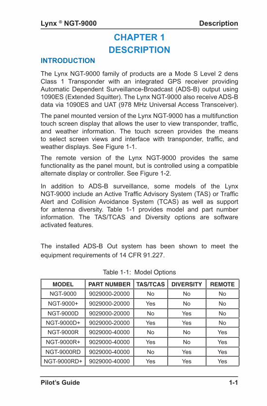
The Lynx NGT-9000 family of products are a Mode S Level 2 dens Class 1 Transponder with an integrated GPS receiver providing Automatic Dependent Surveillance-Broadcast (ADS-B) output using 1090ES (Extended Squitter). The Lynx NGT-9000 also receive ADS-B data via 1090ES and UAT (978 MHz Universal Access Transceiver).
The panel mounted version of the Lynx NGT-9000 has a multifunction touch screen display that allows the user to view transponder, traffic, and weather information. The touch screen provides the means to select screen views and interface with transponder, traffic, and weather displays. See Figure 1-1.
The remote version of the Lynx NGT-9000 provides the same functionality as the panel mount, but is controlled using a compatible alternate display or controller. See Figure 1-2.
In addition to ADS-B surveillance, some models of the Lynx NGT-9000 include an Active Traffic Advisory System (TAS) or Traffic Alert and Collision Avoidance System (TCAS) as well as support for antenna diversity. Table 1-1 provides model and part number information. The TAS/TCAS and Diversity options are software activated features.
MODEL PART NUMBER TAS/TCAS DIVERSITY REMOTE
NGT-9000 9029000-20000 No No No
NGT-9000+ 9029000-20000 Yes No No
NGT-9000D 9029000-20000 No Yes NoNGT-9000D+ 9029000-20000 Yes Yes NoNGT-9000R 9029000-40000 No No Yes
NGT-9000R+ 9029000-40000 Yes No Yes
NGT-9000RD 9029000-40000 No Yes YesNGT-9000RD+ 9029000-40000 Yes Yes Yes
Table 1-1: Model Options
The installed ADS-B Out system has been shown to meet the equipment requirements of 14 CFR 91.227.

Lynx ® NGT-9000
Pilot’s Guide1-2
Description
FUNCTIONAL DESCRIPTIONThe panel mount versions of the Lynx NGT-9000 can display and control the following information:
• Built-In Test and Operational Status• Transponder Functions• Traffic and Weather Output Interfaces• Diversity (optional, model specific)• ADS-B System• Traffic Display• TAS (optional, model specific)• ATAS (Release 2.0 and greater, optional)• TCAS (Release 3.0 and greater, optional, model specific)
Note - The use of TCAS in this Pilot’s Guide refers to a TCAS I system.
• Weather Displays (enable/disable)• Graphical Weather• Winds and Temps Aloft• Textual Weather Reports
• TAWS, Class B (Release 2.0 and greater, optional)• TerrainVisionTM (Panel Mount with Release 2.1 and greater,
optional) Note - The use of TERR Advisory is this Pilot’s guide refers to TerrainVisionTM feature.
• Lightning Detection (Release 2.1 and greater, optional. Panel mount version only)
The remote mount versions of the Lynx NGT-9000 provides the same functionality as the panel mount, but is controlled using a CP-2500 Control Panel (or compatible control panel) and cannot control lightning detection or display TAWS information (callouts and lights only). Display information is shown on a optional compatible display or PED. See Figure 1-2.The unit has multiple transmit/receive ARINC429, RS-422 and RS-232 data ports used to transmit data to traffic, weather, and PED displays. The unit provides the transponder code, reply symbol, and mode of operation to the display.
Figure 1-1: Example of Panel Mount Lynx NGT-9000
MSGON-GND
System Test1200PALT 12000ftID N333TL
IDENTSquawkVFR
ModeALT
-
6ALTALL -01
-08OUT +
IN
00
00

Lynx ® NGT-9000
Pilot’s Guide 1-3
Description
Figure 1-2: Example of Remote Mount Lynx NGT-9000
ADS-B SystemThe ADS-B system used by the Lynx NGT-9000 has the following capabilities:
• 1090 In - Receives ADS-B, ADS-R and TIS-B• 1090ES Out - Transmit ADS-B• UAT In - Receives ADS-B, ADS-R, TIS-B, FIS-BThe Automatic Dependent Surveillance-Broadcast (ADS-B) improves situational awareness and flight safety by providing real time traffic information. The ADS-B In function is used to receive ground station supported TIS-B and ADS-R traffic, and direct communication with ADS-B out equipped aircraft. The ADS-B Out (1090MHz) function is used to periodically broadcast (without interrogation) information about the aircraft that includes aircraft identification, position, altitude, velocity and other aircraft status information.The Automatic Dependent Surveillance – Re-broadcast (ADS-R) is a ground based broadcast service that repeats ADS-B messages from one link (1090ES or UAT) to the other link for aircraft with ADS-B In.
Transponder Diversity OptionsThe Diversity option requires a specific model of the Lynx NGT-9000. This feature offers enhanced transponder operation and traffic awareness via 1090MHz using the ADS-B service. This option requires the installation of an additional top mounted UAT (L-Band) antenna.
TransponderThe transponder function of the Lynx NGT-9000 replies to Mode A, Mode C and Mode S interrogations on 1030 MHz and transmitting responses at 1090 MHz. Transponder operation is performed on the left application screen.

Lynx ® NGT-9000
Pilot’s Guide1-4
Description
Traffic Advisory System (TAS)The Traffic Advisory System (TAS) is an optional feature of the Lynx NGT-9000. This feature provides the capability to interrogate nearby aircraft transponders and issue Traffic Advisory (TA) alert as well as a voice audio output that announces Traffic Advisories and relative altitude to the flight crew. This option requires the installation of a directional antenna.
Traffic Alert and Collision Avoidance System(TCAS)
Release 3.0 or later. The Traffic Alert and Collision Avoidance System (TCAS) is an optional feature of the Lynx NGT-9000. This feature provides the capability to interrogate nearby aircraft transponders and issue Traffic Advisory (TA) alert as well as a voice audio output that announces Traffic Advisories and relative altitude to the flight crew. This option requires the installation of a directional antenna.
ADS-B Traffic Advisory System (ATAS)
Release 2.0 or later. The ATAS [also referred to as TSAA] option provides traffic alerts using ADS-B In (ADS-B, ADS-R, and TIS-B) traffic information. The TA alerts the flight crew aurally and visually in a manner similar to a conventional TAS/TCAS which assists the pilot in the visual acquisition of aircraft that may represent a danger. Traffic Alerts are graphically depicted on the Lynx NGT-9000 panel mount units or on compatible external displays. ATAS and TAS or TCAS may operate at the same time with traffic information being correlated by the unit. Refer to page 2-31 for details on operation.
Traffic DisplayThe Lynx NGT-9000 monitors the airspace around the aircraft using ADS-B In (and TAS or TCAS if equipped) to show other aircraft on the screen. When within range of a participating ground station TIS-B and ADS-R traffic services are also shown on the screen. Traffic is identified on the screen using corresponding traffic symbols.
Traffic Information Service Broadcast (TIS-B) is a ground based broadcast service that provides secondary surveillance radar (SSR) derived traffic data (ATC transponder equipped aircraft not equipped with ADS-B Out capability) to ADS-B In equipped aircraft. The Flight Information Services - Broadcast (FIS-B) function provides pilots with a cockpit display of certain aviation weather and aeronautical information for awareness of own aircraft location with respect to reported weather, including hazardous meteorological conditions.A composite of UAT / 1090ES traffic (UAT, 1090ES, ADS-R, TIS-B, TAS, and TCAS) is provided in Figure 1-3.

Lynx ® NGT-9000
Pilot’s Guide 1-5
Description
Terrain Awareness and Warning System (TAWS)Release 2.0 or later. The Terrain Awareness and Warning System (TAWS) is an optional function that continuously monitors the aircraft’s position, altitude, speed, track, and phase of flight and compares the information to an internal terrain, obstacle, and runway database. If TAWS predicts a potential Controlled Flight Into Terrain (CFIT) situation, the system alerts the pilot visually on the Lynx NGT-9000 display, aurally over the cockpit speakers or headset, or via cockpit lamps (caution & warning).
TerrainVisionTM
Release 2.1 or later. This optional function provides a terrain display (“TERR Advisory”) similar to the TAWS display but without visual or audio alerts. This function is not available for the NGT-9000R Remote Mount version.
Weather Display
The weather displays are optional features setup during installation and when active are shown on the right application screen. Weather information is obtained from the FIS−B system which is a ground broadcast service provided through the ADS−B Services network over the 978 MHz UAT data link. Three screens are available and are designated as follows:
• Graphical Weather• Winds and Temps Aloft• Textual Weather Reports
Traffic and Weather Output InterfacesThe Lynx NGT-9000 can output traffic information via ARINC 429 and RS-422. Weather information is output via RS-422. Weather and traffic can be output on RS-232 via WiFi to be viewed on a personal electronic device.
Built-In Test and Operational StatusThe Lynx NGT-9000 uses fault monitoring on all stages of operation from start up to power down and provides screen messages for degraded or failed operation. In addition a system test is available providing operational status of external data inputs.

Lynx ® NGT-9000
Pilot’s Guide1-6
Description
Figure 1-3: Example of Own Aircraft UAT, 1090ES, & TAS/TCAS Traffic
70 nm ( )TAS/TCAS
+/- 1
0000
(TAS
/TC
AS)
+/- 3
500
ft (T
IS-B
)
Own AircraftUAT / 1090ES
TAS/TCAS(model option)
+/- 5
000
(AD
S-R
)
30 nm ( / )TIS-B ADS-R
ATC - Ground Station
Other AircraftUAT Non-Equipped
Mode A/C Equipped
TIS-B
Other Aircraft UAT
FIS-B
TIS-B
Other AircraftTAS/TCAS
Other Aircraft 1090ES
ADS-R
Lightning DetectionRelease 2.1 or later. Lightning Detection is an optional function provided by the interface of a WX-500 Stormscope. This information is shown on the right application screen of the NGT-9000 Panel Mount unit. This function is not available for the NGT-9000R Remote Mount version.

Lynx ® NGT-9000
Pilot’s Guide 1-7
Description
EQUIPMENT DESCRIPTION
The Lynx NGT-9000 MSS family consists of the following standard and optional equipment. Refer to the Aircraft Flight Manual Supplement to determine what optional equipment is installed. Chapter 5 provides a list of optional cockpit switches and lamps.
Required Equipment• GPS Antenna• L-Band (978MHz/1030/MHz/1090MHz) Antenna• Detachable Configuration Module (DCM)
Optional Equipment• Directional Antenna (required for TAS or TCAS operation, and
models with TAS/TCAS and diversity operation)• Additional L-Band Antenna (required for diversity operation, and
no TAS/TCAS operation)• Traffic Display• Weather Display• WiFi Serial Adapter and Personal Electronic Device (PED)• CP-2500 (or compatible) Control Panel (required for the remote
mount version) • WX-500 Stormscope (panel mount version only)
GPS Antenna and Internal GPS Receiver
The GPS utilizes signals from Global Positioning System (GPS) satellite constellation and Satellite-Based Augmentation Systems (SBAS). The Lynx NGT-9000 has an internal GPS function that pro-vides position, velocity, time and integrity (NIC, NAC etc) information to the applications. The antenna is located on the top of the aircraft.
L-Band AntennaThe L-Band antenna is used by the Lynx NGT-9000 to receive 1030MHz, receive and transmit 1090MHz and receive 978MHz. It is located on the bottom of the aircraft. A second L-Band antenna is installed on the top of the aircraft for models with Diversity. Installations with either TAS or TCAS and Diversity options use the TAS/TCAS directional antenna instead of the second L-Band antenna.
Lynx ® NGT-9000
Pilot’s Guide1-8
Description
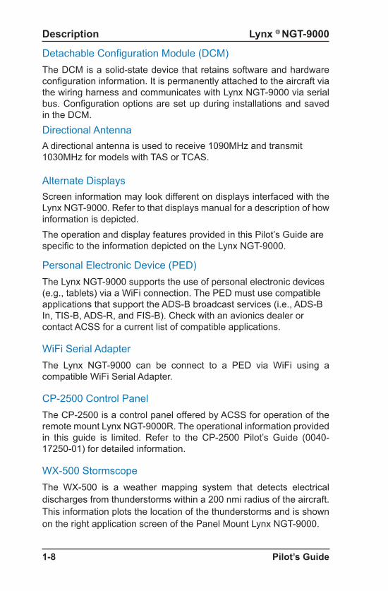
Detachable Configuration Module (DCM)The DCM is a solid-state device that retains software and hardware configuration information. It is permanently attached to the aircraft via the wiring harness and communicates with Lynx NGT-9000 via serial bus. Configuration options are set up during installations and saved in the DCM. Directional AntennaA directional antenna is used to receive 1090MHz and transmit 1030MHz for models with TAS or TCAS.
Alternate DisplaysScreen information may look different on displays interfaced with the Lynx NGT-9000. Refer to that displays manual for a description of how information is depicted. The operation and display features provided in this Pilot’s Guide are specific to the information depicted on the Lynx NGT-9000.
Personal Electronic Device (PED)The Lynx NGT-9000 supports the use of personal electronic devices (e.g., tablets) via a WiFi connection. The PED must use compatible applications that support the ADS-B broadcast services (i.e., ADS-B In, TIS-B, ADS-R, and FIS-B). Check with an avionics dealer or contact ACSS for a current list of compatible applications.
WiFi Serial AdapterThe Lynx NGT-9000 can be connect to a PED via WiFi using a compatible WiFi Serial Adapter.
CP-2500 Control PanelThe CP-2500 is a control panel offered by ACSS for operation of the remote mount Lynx NGT-9000R. The operational information provided in this guide is limited. Refer to the CP-2500 Pilot’s Guide (0040-17250-01) for detailed information.
WX-500 StormscopeThe WX-500 is a weather mapping system that detects electrical discharges from thunderstorms within a 200 nmi radius of the aircraft. This information plots the location of the thunderstorms and is shown on the right application screen of the Panel Mount Lynx NGT-9000.

Lynx ® NGT-9000
Pilot’s Guide 2-1
CHAPTER 2OPERATION - PANEL MOUNT
INTRODUCTIONThis chapter describes the operation of the Panel Mount version of the Lynx NGT-9000. Details on the optional cockpit switches and indicator lamps are provided in chapter 3.
PILOT ADVISORY
The display of ADS-B data only supplements and does not replace any operational procedure. All pilots/operators are reminded that the airborne equipment that displays traffic is only for pilot situational awareness. This equipment is not approved as a collision avoidance tool and does NOT relieve the pilot of responsibility to “see-and-avoid” other aircraft. Any deviation from an air traffic control clearance based on cockpit information must be approved by the controlling ATC facility prior to commencing the maneuver. Uncoordinated deviations may place an aircraft in close proximity to other aircraft under ATC control not seen on the airborne equipment and may possibly result in the issuance of a pilot deviation.
• Occasionally the traffic display may show a “shadow” or duplicate of your own aircraft on the traffic display. Generally this is caused by a TIS-B track of the aircraft reported from a ground station. In most cases, the own aircraft TIS-B tracks are detected and filtered out by the NGT software. In some cases, own aircraft maneuvers can cause enough separation of the TIS-B track from own aircraft that it is treated as a new intruder and displayed. This is not an error or malfunction in the system. As ground stations improve, the occurrence of these shadows should be minimized or eliminated.
• Ground stations only produce TIS-B intruders for Mode C/S equipped aircraft that have no ADS-B output. Mode A or non-transponder equipped aircraft are not reported as TIS-B intruders. It is the pilots responsibility to “see and avoid”.
• Information shown on the display is provided to the pilot as an aid to visually acquiring traffic. When under ATC control pilots should maneuver their aircraft based only on ATC guidance or positive visual acquisition of the conflicting traffic. Maneuver should be consistent with ATC instructions. ATC should be contacted for resolution of the traffic conflict.

Lynx ® NGT-9000
Pilot’s Guide2-2
Operation - Panel Mount
POWER ON1. Depending on the aircraft use either the battery switches or
avionics master switch to apply power.2. After power is applied the unit begins initialization and self-tests
begin. 3. When on ground the unit cycles through the following screen
sequence:
• Splash• System Status / Version • Flight ID (optional)• Normal Operation
4. When in air and power is cycled the unit transitions to normal operation within 5 seconds, bypassing the splash, version, and flight ID screens.
Splash ScreenThe splash screen is displayed in less than 5 seconds after power is applied. The company name/Logo is shown on the left side and the product name on the right. See Figure 2-1.
Figure 2-1: Example of Splash Screen
• The transponder signal must be transmitting during all flight and ground operations. It may be placed in standby only if the system is inoperable or if advised by ATC to disable ADS-B.
• Loss of input data may not cause the NGT-9000 to fail but could degrade operation. Failure and degraded conditions will be annunciated by the NGT-9000 to alert the pilot to the operational status. In many cases, fault conditions will recover if erroneous data inputs are restored.
• Aircraft will be displayed when the information received meets ADS-B, ADS-R, and TIS-B data integrity requirements.

Lynx ® NGT-9000
Pilot’s Guide 2-3
Operation - Panel Mount
System Status / Versions Screen
The system status is shown on the left screen and should show “System Pass” in green text along with an audio indication of “System Test Passed”. The version screen is located on the right side and shows the software and database version information. See Figure 2-2.
Figure 2-2: Example of System Status / Version Screens
• If System Status is “System Fail”, then the message “Self-Test Failures Occurred” is shown on the right side of the display and the “System Test Failed” is heard through the aircraft audio system. The option to restart the unit or to continue start up in a degraded mode is shown on the right side of the display • Tap the Restart button to restart the system. • If the “System Fail” message continues to be seen tap the
Continue button to proceed. Refer to Chap. 5 (Troubleshooting) for corrective actions.
• If System Status is “System Degraded”, then the message “See MSG Window” is shown on the right side of the display. • Tap Continue button to proceed. Refer to Chap. 5
(Troubleshooting) for corrective actions.
System Status
System PassPower On Result:
Versions
Flight Sw: 0000-00000-XXYZGPS/UAT RX: _ _ _ _ _ _ _Airport DB: YYYYMMDDMap DB: YYYYMMDDTAWS DB: YYYYMMDD
Flight ID Screen (optional)
The Flight ID Screen is a configuration option that must be setup during installation. Most general aviation aircraft will be operated in a manner that does not require Flight ID. See Figure 2-3. It is shown after the System Status/Version Screen and shows the following information:
• Use Tail # (call sign) button, located in the upper left, may be tapped to be activated in place of a Flight ID.

Lynx ® NGT-9000
Pilot’s Guide2-4
Operation - Panel Mount
Figure 2-3: Example of Flight ID Screen
Normal OperationFigure 2-4 shows an example of the unit in normal operation. When the aircraft is on ground the System Test button and ON-GND indication are shown. Functional instructions are located in the Basic Operation section below.
Figure 2-4: Example of Normal Operation
MSGON-GND
System Test1200PALT 12000ftID N333TL
IDENTSquawkVFR
ModeALT
-
6ALTALL -01
-08OUT +
IN
00
00
Application Indicators
Release 1.x and 2.x
Release 3.x
• The Flight ID Number is entered using the keypad. For Release 1.x/2.x the keypad will change to numbers after three alpha characters are entered. For Release 3.x or later tap the “123”, “A-M” or “N-Z” button to change the keyboard buttons as needed. When complete, tap the Done button to proceed to normal operation.
• The Flight ID from the previous power cycle is retained if the unit went in-air.
• The Flight ID can be changed using the Flight ID Button in the options setting.

Lynx ® NGT-9000
Pilot’s Guide 2-5
Operation - Panel Mount
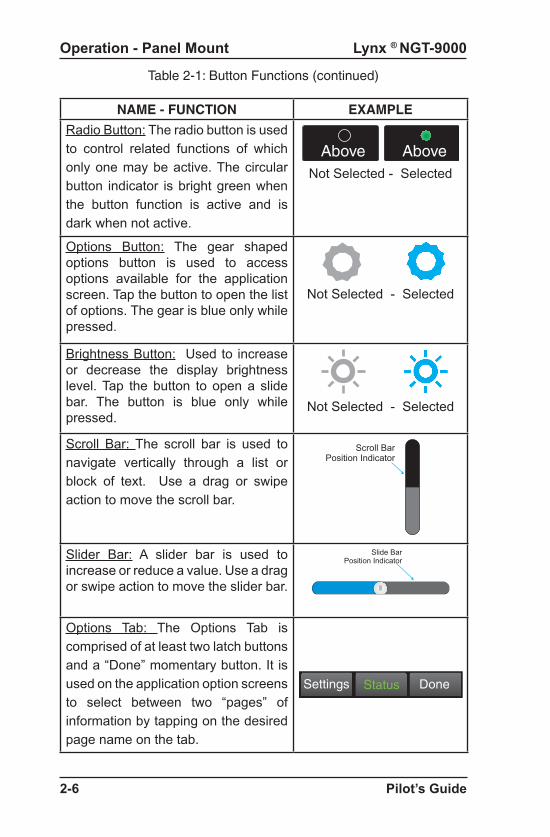
Table 2-1: Button Functions
NAME - FUNCTION EXAMPLE
Momentary Button: Use a tap action on the momentary button to perform a onetime function
Done
Latch Button: Use a tap action on the latch button to set a single function to On or Off. Once pressed the button retains the latched appearance indicating that it is active.
Settings
Not Selected - Selected
Toggle Button: The toggle button is used to control related functions of which only one may be active at a time. Performs a onetime action when pressed that changes the selected indicator located at the bottom of the button. The background is blue only while pressed.
ModeALT
Not Selected - Selected
BASIC OPERATIONThe touch screen display is divided into left and right screens that show information specific to the selected application. The user can select, input, and adjust information on the screen using buttons, edit boxes and screen objects using gestures (actions) such as tap, momentary press, drag, or swipe.
Screen ButtonsThe buttons are used to select, input, and adjust screen information. The buttons have the following common functionality:
• Buttons are typically gray background color with white or green text.
• The shape of a button can vary according it’s location. • The button background highlights in blue when pressed.• A button function that is inhibited has its button label grayed out.
Table 2-1 provides examples of screen buttons, edit boxes, and other screen objects and their functionality.
Status
ModeALT
Lynx ® NGT-9000
Pilot’s Guide2-6
Operation - Panel Mount
NAME - FUNCTION EXAMPLE
Radio Button: The radio button is used to control related functions of which only one may be active. The circular button indicator is bright green when the button function is active and is dark when not active.
Above AboveNot Selected - Selected
Options Button: The gear shaped options button is used to access options available for the application screen. Tap the button to open the list of options. The gear is blue only while pressed.
Not Selected - Selected
Brightness Button: Used to increase or decrease the display brightness level. Tap the button to open a slide bar. The button is blue only while pressed.
Not Selected - Selected
Scroll Bar: The scroll bar is used to navigate vertically through a list or block of text. Use a drag or swipe action to move the scroll bar.
Scroll BarPosition Indicator
Slider Bar: A slider bar is used to increase or reduce a value. Use a drag or swipe action to move the slider bar.
Slide BarPosition Indicator
Options Tab: The Options Tab is comprised of at least two latch buttons and a “Done” momentary button. It is used on the application option screens to select between two “pages” of information by tapping on the desired page name on the tab.
DoneSettings Status
Table 2-1: Button Functions (continued)

Lynx ® NGT-9000
Pilot’s Guide 2-7
Operation - Panel Mount
NAME - FUNCTION EXAMPLE
Selection List: Selection Lists are used where there is a list of items from which a selection can be made. A green filled circle is shown when an item is selected. A drag or swipe action is used to scroll the list up or down.Message Window: The message window is used when a system message is present that requires a user response. Two function active buttons can be arranged in a row below the message text.
Self-Test FailuresOccured!
Self-Test FailuresOccured!
Restart Continue
Message Text
Function ActivateButtons
On/Off Button: This button is used to indicate whether a function is enabled (green) or disabled (dark).
Table 2-1: Button Functions (continued)
Application ScreensThe display is divided into left and right screens with each screen having access to a particular application. An Application indicator is located at the bottom of each screen. The indicator shows the number of available applications for that side of the display as well as the current application setting. Each application can slide into view using both Drag and Swipe actions. See Figure 2-4.
Left ScreenThe left screen has two application indicators. The first indicator (from left to right) corresponds to the Transponder the second indicator corresponds to Alternate Traffic.
The Transponder screen Displays Mode A Squawk Code, Pressure Altitude, Flight ID or Call Sign (tail number).
The Alternate Traffic screen displays a Birds-eye display of traffic and own-ship compliant with the requirements of AC 20-172B and DO-317B for the purpose of supporting the Enhanced Visual Acquisition (EVAcq) and Basic Airborne (AIRB) CDTI applications.

Lynx ® NGT-9000
Pilot’s Guide2-8
Operation - Panel Mount
Right ScreenThe right screen has between two and six application indicators. The number of indicators is dependent on the feature enablement.
The two screens that are always available are the Traffic and the FIS-B Graphical Data Screen.
The Traffic Birds-eye display of traffic and ownship for the purpose of supporting the Enhanced Visual Acquisition (EVAcq) and Basic Airborne (AIRB) CDTI applications. This includes display of traffic advisories, when installed and enabled (TAS, TCAS, or ATAS Optional).
The FIS-B Weather Graphic screen is a simplified moving map display with depiction of ownship and the ability to selectively overlay graphical FIS-B products such as METAR, TAF, NOTAMs, AIRMET, SIGMETs, TFR and NEXRAD.
The following four screens are dependent on the feature enablement: TAWS (or Terrain Display Only - No Alerting), Lightning, FIS-B Graphical Winds and Temps Aloft, and FIS-B Textural Data.
The Terrain Awareness and Warning System screen displays a birds-eye display of terrain, obstacles, airports, and ownship for the purpose of supporting a Class B TAWS. Release 2.1 or later also includes an option for Terrain Display only with No Alerting.
The Lightning screen displays electrical discharges from thunderstorms within a 200 nmi radius of the aircraft. This Lightning data depicted as cells or strikes. A “Nearby Strike Indicator (lightning bolt)” is shown over the lightning application Dot when storm activity is detected.
The FIS-B Weather Graphic Winds & Temp Aloft screen is a simplified moving map display with depiction of ownship and the ability to selectively overlay winds and temps aloft at the desired flight level.
The FIS-B Weather Textual Data screen displays airport associated textual products provided by FIS-B including METAR, TAF, NOTAMs.
The application indicators and their screens have the following order (from left to right) when enabled: Traffic, TAWS, Lightning, FIS-B Graphic Data, FIS-B Graphical Winds & Temps Aloft, and FIS-B Textual Data.

Lynx ® NGT-9000
Pilot’s Guide 2-9
Operation - Panel Mount
Figure 2-5 Transponder Application Screen
TRANSPONDER OPERATION
The transponder receives interrogations from surrounding aircraft and from ATC and then transmits replies.
Ground stations can interrogate Mode S Transponders individually using a 24-bit ICAO Mode S address, which is unique to the particular aircraft. In addition, ground stations may interrogate the unit for its transponder data capability and the aircraft’s Flight ID.
The transponder application is the first screen on the left side of the display as indicated by the application indicator. See Figure 2-5 and the functional description below for operating instructions.
Release 2.1 or later. An external Standby Mode switch and pilot option to enable or disable the “Squawk VFR” button is available. See Chapter 4 for details on Transponder screen and operation changes.
Squawk Code
When the Squawk Code text is tapped, the Squawk Code Edit Screen is shown. See Figure 2-6. The current Squawk Code continues to be transmitted until the last digit of the new Squawk Code is entered. The edit mode is canceled by tapping the Squawk Code before the fourth digit is entered, or after 5 seconds of inactivity, or if a Traffic Advisory or TAWS Alert occurs.
MSG
ON-GND ON-GNDIndication
System TestIDENT1200
IDENTSquawkVFR
ModeALT
PALT 12000ftID N333TL
Application Indicator
Mode ASquawk
Code
PressureAltitude
Flight IDor
Call Sign
Transponder ActiveIDENT or Reply Message
Function Button(On Ground Only)
Squawk ButtonXPDR ModeControl
IDENTButton
MessageButton

Lynx ® NGT-9000
Pilot’s Guide2-10
Operation - Panel Mount
Current Pressure AltitudeThe current pressure altitude (PALT) is located below the Squawk Code. A value greater than 99,900 ft will set the value to 99900 with amber text. An invalid pressure altitude is shown as amber dashes.
Flight ID / Call Sign
The Flight ID or Call Sign (tail number) is located below the PALT. During initial installation either the tail number is setup to be shown or the Flight ID can be set each flight using the Flight ID screen (configuration option).
Mode ControlThe Mode Control toggle button has the following selections: Standby (Sby), On, and Altitude (Alt).
• ALT is the default mode. It puts the transponder in ATC mode C. When the aircraft is In-Air the transponder replies to interrogations and includes the plane’s pressure altitude in the replies. The transponder should be in this setting when In-Air or On-Ground unless otherwise directed by ATC. When On-Ground, the display includes an “ON-GND” indication. While On-Ground the transponder does not reply to Mode C/S All-Call interrogations and outputs ADS-B at a slower surface rate.
• Selecting Standby stops all transponder transmission.• Selecting ON puts the transponder in ATC mode A in which it
replies to interrogations, but does not report the plane’s altitude.
A “FAIL” message, in amber text, is shown if a transponder failure is detected.
Transponder ReplyWhen the transponder (XPDR) reply is active an “R” indicator is shown to the right of the Squawk Code. The “R” is replaced with “IDENT” when the IDENT button is tapped.
IDENT ButtonTap the IDENT button to transmit the Special Identification (SPI) pulse. An IDENT pulse highlights the aircraft’s symbol on the ATC’s radar screen and is identified on the screen next to the squawk code.

Lynx ® NGT-9000
Pilot’s Guide 2-11
Operation - Panel Mount
Squawk VFR ButtonTap the Squawk VFR toggle button to change the transponder squawk code to a predefined (1200) VFR value. The value shown on the button is the code that is activated when the button is tapped. A second press reverts the transponder to the previous squawk code.
Gain access to the Squawk Code Edit Screen from the Traffic page as follows: Tap the Options (the Gear symbol), Settings, and VFR Code button. See figure 2-6.
Release 2.1 or later. The Squawk button can be removed from the transponder screen. Do this by entering the edit screen and tapping the Enabled button. The buttons green light turns gray and is shown as “Disabled”.
Done
1200VFR Code
Cancel
ENABLED
X
0 12 34 56 7
Figure 2-6: Squawk Code Edit Screen
MSG ButtonIf a new message is available a flashing MSG button is shown on the left screen. Tap the MSG button to view fail or degraded messages during normal operation.
Once the messages in the message window have been viewed, the MSG button will stop flashing. When all messages have cleared, the MSG button is removed from the screen. On the Message window tap the Done button to return to the previously viewed screen.
Refer to the Chap. 5 (Troubleshooting) for corrective actions.
ON-GND IndicatorThe ON-GND indicator provides the pilot a notification that the transponder is operating in the on-ground mode (does not reply to all-calls).
System Test ButtonThe System Test button is available only when the aircraft is on the ground. Tapping the button initiates the Test. During the System Test the user functions are disabled and the right screen shows a preset traffic display with the message “Self Test In Progress” at the top of the screen. See Figure 2-7.

Lynx ® NGT-9000
Pilot’s Guide2-12
Operation - Panel Mount
Figure 2-7: Example of System Test Screen
System StatusPassPassPassFailPassPassDegraded
ADS-B In:ADS-B Out:Transponder:FIS-B:TAS:ATAS:TAWS:
6+10
-02
Self Test In Progress
-10
The left screen shows the system affect of the tests results on the functional areas of the system.Note – Release 1: Functions that are not part of the installation are not shown. Release 2.0 or later: TAS, ATAS, and TAWS are listed with a “disabled” indication if not installed. Release 3.0 or later: TCAS is listed with a “disabled” indication if not installed. FIS-B is removed from the list if it is disabled.Note - Individual test failures are recorded in the fault log. (Accessible to service personnel only.)The unit returns to normal operation if no failures are detected within 5 seconds. • If a “Fail” or External Fail” is shown for any of the system functions,
then the message “Self-Test Failure” is shown on the right side of the display as well as the option to restart the unit or to continue operation in a degraded mode. • Tap the “Restart” button to reset the unit and once it is operational,
perform the System Test again. If the failures continue tap the “Continue” button to proceed in a degraded operational mode.
• If “Degraded” is shown for any of the system functions, then the message “Service Unit Soon” is shown on the right side of the display. • Tap Continue screen button to proceed.
Correct failures before going any further with the functional check. Note: It is normal to show degraded for certain functions if some aircraft systems are still aligning, or if the GPS has not yet acquired a signal.• On the Transponder Screen, tap the “MSG” button located on the
Transponder Application screen to view fail messages. • Check signal availability when failures for ADS-B In, FIS-B, GPS,
TAS, or TCAS are noted.
• Refer to the Chap. 5 (Troubleshooting) for corrective actions.

Lynx ® NGT-9000
Pilot’s Guide 2-13
Operation - Panel Mount
TRAFFIC OPERATIONThe Lynx Multi-Link Surveillance System monitors the airspace around the aircraft using ADS-B In (and TAS/TCAS if equipped) to communicate with like equipped aircraft with ADS-B Out and shows these other aircraft on the screen. When within range of a participating ground station TIS-B and ADS-R traffic services are also shown on the screen. Traffic is identified on the screen using corresponding traffic symbols. Refer to the descriptions below and Figure 2-8 for detailed information.
Limitations• The ADS-B, ADS-R, TIS-B, TAS, and TCAS traffic information
assists the pilot in visually acquiring traffic while airborne and is expected to improve both safety and efficiency by providing the pilot with enhanced traffic awareness. This functionality does not relieve the pilot of “see and avoid” responsibilities as described in 14 CFR 91.113b.
• Traffic information shown on the Lynx NGT-9000 is dependent on other aircraft having similar ADS-B equipment, or a Mode A/C transponder for models with TAS/TCAS, or being in range of a ground station that provides TIS-B and ADS-R. If another aircraft cannot meet these requirements, then the other aircraft will not be displayed on the Lynx NGT-9000.
• The EVAcq, AIRB, and ATAS functions are unavailable when ownship position is beyond 85 degrees North or South latitude. The result is a display of “Traffic Unavailable” on Panel mount units and an indication of “Standby” for remote displays. However, for NGT-9000 installations, where TAS or TCAS is enabled, the range/bearing based TAS/TCAS targets are displayed.
• Some Aircraft may be equipped with an external CAWS or TAWS type system that has higher priority audio annunciation that will delay traffic or terrain alerts.
Traffic AdvisoryThe TAS, TCAS, and ATAS functions are optional features providing advisories via aural announcements over the cockpit speakers or headset and visually via the display or a cockpit lamp. ATAS and TAS or TCAS may operate at the same time with traffic information being correlated by the Lynx NGT-9000. Details on these features are shown in “Traffic Alerting” on page 2-30.

Lynx ® NGT-9000
Pilot’s Guide2-14
Operation - Panel Mount
Traffic ScreenThe traffic screen has a black background. Transponder Mode can be set to Standby (SBY), On (ON), or Altitude (ALT).
The Traffic application is available on both the left and right screen. The Traffic information is shown if ADS-B, TAS, TCAS data is valid.
A “Traffic Failed” is displayed if both ADS-B and TAS/TCAS (optional) are failed. “Traffic Unavailable” is displayed if ADS-B In has no heading or track available and TAS/TCAS (if installed) is in standby. See Figure 2-8 for an example of Traffic Screens. Refer to the Functional Description below for detailed information. If TAS, TCAS and ATAS options are configured and the traffic screen is not being displayed on either the left or right screen and a traffic advisory occurs, the traffic screen automatically opens on the right screen if there is no TAWS Alert (option) active and will open on the left screen if a TAWS alert is active.
Figure 2-8: Traffic Applications Screen
6
ALTNRM
-01
-08
00
00
N333TL150 kts
OnXPDRi
MSG
1200
+In
-Out
6ALTNRM -01
-08
00
00
i
N333TL150 kts
-Out
TASSTBY
TASSTBY
Zoom In
RangeIndication
SelectedTraffic Info Button
OptionsButtonTransponder
BannerSelectedTraffic GS
Zoom OutDirectional OwnshipAltitudeMode
Circle indicates symbol is selected
Acknowledge Button
SelectedTraffic ID
Traffic Mode Indicator
+In
Transponder Mode
TIS-B No Coverage Indicator
TIS-B No Coverage Indicator

Lynx ® NGT-9000
Pilot’s Guide 2-15
Operation - Panel Mount
Ownship Symbol The ownship is shown as a white triangle on the traffic display. When ownship direction source is not valid the ownship symbol is a white circle with a black inset. Ownship orientation matches ownship heading when available or track angle if heading is not available.
Traffic SymbolsThe traffic symbols indicate the approximate range, relative bearing, and relative altitude of intruder aircraft. Traffic data with directional data for intruder aircraft are shown as arrowheads. Traffic data without directional data for intruder aircraft are shown as diamonds.
• A solid amber circle (or with a black filled arrowhead) is a Traffic Advisory (TA) that represents an intruder aircraft that may pose a collision threat. (A semi-circle at the edge of the display represents an off-scale TA).
• Units with the optional TAS or TCAS feature (e.g., NGT-9000+ or NGT-9000R+) display traffic advisory symbols and output aural TA warnings (Release 1 “traffic, traffic” or Release 2.0 or later “Traffic” with the other aircraft clock position) that are annunciated over the cockpit speaker or headset. Note - Optionally available extended call-outs including the relative attitude and range (low, 5 miles). This is a configurable option selected at the time of installation.
• Units with the optional ATAS feature (Release 2.0 or later) display traffic advisory symbols and output aural TA warnings (“Traffic” along with the other aircraft clock position) that are annunciated over the cockpit speaker or headset. Note - Optionally available extended call-outs including the relative attitude and range (low, 5 miles). This is a configurable option selected at the time of installation.
• A solid diamond or arrowhead is a Proximity Advisory (PA) that represents traffic that is close but does not pose an immediate collision threat.
• A hollow diamond or arrowhead indicates Other Traffic (OT) that represents traffic that does not pose an immediate threat.
• Directional intruders are oriented such that symbols point in the direction of their reported heading or track, relative to own aircraft direction.

Lynx ® NGT-9000
Pilot’s Guide2-16
Operation - Panel Mount
• A velocity vector arrow may be appended to the right side of a traffic symbol to indicate that the intruder aircraft is ascending (up arrow) or descending (down arrow) faster than 500 fpm. No arrow is shown for intruder aircraft in level flight, or for those moving vertically slower than ±500 fpm, or for non-altitude-reporting intruder aircraft.
• A two digit number may be appended to traffic symbols to indicate, in hundreds of feet, the relative altitude of the intruder. For example +03 means the intruder aircraft is 300 ft above ownship. A positive data tag is displayed above the traffic symbol to emphasize that the intruder aircraft is above your aircraft. A negative data tag is displayed below the traffic symbol. If the intruder is at the same altitude as the aircraft, “00” is displayed below the traffic symbol. The data tag for a vertically out of range TA displays the relative altitude of the intruder regardless of the current vertical display mode. Only display data tags for altitude reporting aircraft are shown. Non-altitude reporting aircraft are considered to be at the same altitude as ownship.
• Tapping a traffic symbol generates a circle around it indicating that the traffic symbol is selected. In addition the following is displayed: Selected Traffic Info Button, Selected Traffic ID, and if enabled the Selected Traffic Ground Speed (GS). Tap the traffic symbol again to remove the circle and data. Once an aircraft is selected, more data (if available) can be seen by tapping the “i “ button.
• When TAS/TCAS functionality is enabled and in installations with no heading source, the TAS/TCAS traffic (referenced to the heading/nose of the aircraft) and ADS-B traffic (referenced to track) are displayed simultaneously. The ADS-B targets will therefore appear skewed by the crab angle of the aircraft.
• When TAS/TCAS functionality is enabled and in installations with no heading source, low speed operations (< 7 knots) will result in a removal of the ADS-B tracks because ownship track can not be adequately determined. TAS/TCAS Only text will appear on the display if TAS/TCAS is enabled. This can happen in both rotorcraft hover operations and when fixed wing/rotorcraft aircraft are on-ground.
See Table 2-2 for a list and description of traffic symbols used by the panel mount unit.

Lynx ® NGT-9000
Pilot’s Guide 2-17
Operation - Panel Mount
Table 2-2: Traffic Symbols
SYMBOL DESCRIPTION - EXAMPLE
Airborne Directional Traffic Advisory (TA) (TAS, TCAS, or ATAS option only)
Airborne Directional Proximity Advisory (PA) *
Airborne Directional Other Traffic (OT) * (Panel mount only)
Airborne Non-directional (TA) (TAS, TCAS, or ATAS option only)
Airborne Non-directional (PA) *
Airborne Non-directional (OT) *
On Ground Directional (OT)
Ground Vehicle Directional
On Ground Non-directional (OT)
Ground Vehicle Non-directional
-01
Airborne Directional TA Traffic symbol with a data tag indicating a relative altitude of 100ft below with a horizontal velocity vector. (Panel mount only)
-08
Airborne Directional Other Traffic symbol with a data tag indicating a relative altitude of 800ft below own aircraft descending with a horizontal velocity vector. (Panel mount only)
* To promote cockpit commonality, installation configuration options are available to set the airborne PA & OT traffic color to either cyan or white.

Lynx ® NGT-9000
Pilot’s Guide2-18
Operation - Panel Mount
Traffic Display PriorityWhen multiple intruders are displayed, some overlapping of symbols and/or data may occur. In these instances, the intruder with the greatest threat partially or completely overlaps the intruders that pose lower threats. Threat levels are calculated based on the intruders’ proximity, heading, altitude, and speed. Traffic is displayed on the screen using the following priority scheme:
1. TAS/TCAS Traffic Advisories2. ATAS Traffic Alerts3. Selected Traffic4. Proximate Advisories5. Other Traffic
Traffic Altitude Mode
The available Traffic Altitude Modes are shown on a Toggle button with green text. The altitude ranges are in relation to the ownship. A description of each mode is detailed below:
• Normal (NRM): Traffic is displayed from altitudes of between -2,700 and +2,700 ft. This mode is typically used during the enroute phase of flight to reduce screen clutter.
• Above (ABV): Traffic is displayed from altitudes of between +9,000 and -2,700 ft. This mode is typically used during takeoff.
• Below (BLW): Traffic is displayed from altitudes of between +2,700 and -9,000 ft. This mode is typically used during approach and landing.
• Unrestricted (UNR): Traffic is displayed from altitudes of between +9,900 and -9,900 ft. This mode is typically used during the enroute phase of flight to show all aircraft within the entire detection area.
The Altitude Mode button is available only when the status of the aircraft is In-Air. When the aircraft status is On-Ground the altitude mode button is replaced with the TFC button.See Figure 2-8 for a graphic representation of the Traffic Display Modes and Traffic Zones.

Lynx ® NGT-9000
Pilot’s Guide 2-19
Operation - Panel Mount
Zoom ButtonsZoom In (+) and Zoom Out (-) buttons are located on the bottom of each traffic screens. The buttons are used to change the traffic display range.
Range RingsThe range rings are oriented around the ownship. A range indicator is located outside the upper left corner of the outer most ring. Bearing indicators are shown on the 2 nm range ring. The range ring setting is controlled by the zoom buttons.
The Traffic screen has the following display range with additional inner rings as noted:
• Range 40 has 40 nm and 24 nm range rings. • Range 24 has 24 nm and 12 nm range rings. • Range 12 has 12 nm and 6 nm range rings. • Range 6 has 6 nm and 2 nm range rings. • Range 2 has only the 2 nm range ring. • Range 1 has only the 1 nm range ring. • Range 0.5 has only the 0.5 nm range ring.
TFC Button
The Traffic (TFC) button replaces the Traffic Altitude Mode button when the status of the aircraft is On-Ground. The button also activates TAS/TCAS (optional) when the aircraft is On-Ground. A description of each mode is detailed below:• Ground (GND): The display shows ADS-B ground traffic only and
places TAS/TCAS (if installed) in Standby. TAS or TCAS Standby indication is located on the Traffic Mode Indicator. This is the default mode when the aircraft goes on ground.
• Air (AIR): The display shows air traffic only and activates TAS/TCAS (if installed).
• All (ALL): The display shows air and ground traffic and activates TAS/TCAS (if installed).
NoteWhen no heading source is available and when going through low speed operations (< 7 knots), ADS-B tracks are removed because ownship track can not be adequately determined. If TAS/TCAS is not active, a “Traffic Unavailable” message is displayed.

Lynx ® NGT-9000
Pilot’s Guide2-20
Operation - Panel Mount
Transponder BannerWhen the traffic application is displayed on the left screen, the transponder banner is displayed at the top of the left screen with the following information:
• Quick return button is labeled “XPDR” and is used to return to the Transponder Application screen
• Mode A squawk code• Reply “R” or Ident “ID” indicator shown to the right of the squawk
code when either function is active. • Current transponder operating mode status indicator with green
text. An amber “XPDR Failed” is shown when the transponder function has failed.
Traffic Mode IndicatorThe Traffic Mode Indicator is available only when a Lynx NGT-9000 with TAS/TCAS is installed. Otherwise the “ADS Only” is assumed to be operating for non-TAS or non-TCAS installs.
The indicator is located above the Zoom in (+) button. The possible modes of operation are detailed below:
• TAS STBY: This mode is shown if the TAS is in standby.• TAS Only: This mode is shown if the TAS is operating and ADS-B
traffic is not available. • TCAS STBY: This mode is shown if the TCAS is in standby.• TCAS Only: This mode is shown if the TCAS is operating and
ADS-B traffic is not available. • ADS Only: This mode is shown if TAS/TCAS has failed (or not
available) and ADS is operating. A “Traffic Failed” message is shown with amber text when all available traffic functions have failed. This results in all the traffic symbols being removed from the traffic screen. A “Traffic Unavailable” is shown with white text when insufficient information is available to display traffic. This results in all the traffic symbols being removed from the traffic screen.
MSG ButtonThe MSG Button seen on the Traffic Screen has the same functionality as the one shown on the Transponder screen. See page 2-11 for details.
Traffic Options ButtonThe gear shaped Options Button is located in the upper right corner of the right application screen. Tap the button to open the options screen.

Lynx ® NGT-9000
Pilot’s Guide 2-21
Operation - Panel Mount
Figure 2-9: Traffic Options Screen - Status
Traffic Options ScreenTwo latch buttons and a done button are located on the bottom. The Status button opens a screen showing GPS satellite information. The Settings button opens a screen allowing the setting of Initial Traffic Altitude Mode, VFR Squawk Code, Display Brightness Trim, and Flight ID (if configured). Tap the Done button to close the Options Screen.
Options - StatusSee Figure 2-9. The status screen provides the following GPS information:• 24 Bit ICAO ID (Mode S Identifier): This value is displayed in octal
format. • NACp (Navigation Accuracy Category for Position): This value is
determined using HFOM data. • NIC (Navigation Integrity Category): this value is determined
using HPL data. • Navigation Solution Mode (GPS), possible indications are:
• “No Pos” - unknown or DR [Insufficient Satellites to compute a position]
• “2D” - 2D Nav, no integrity [Sufficient satellites to compute a lateral position, but not to compute either HPLSBAS or HPLFD]
• “3D” - 3D Nav, no integrity [Sufficient satellites to compute a lateral and vertical position, but not to compute either HPLSBAS or HPLFD]
• “FDE” - RAIM/Alt (aided integrity) [HPLFD computed using barometric altitude aiding is valid]
• “WAAS” - RAIM [HPLSBAAS is valid or HPLFD computed without using barometric altitude aiding is valid]
• “Error” - SVERROR (trying to exclude) [Fault detection detects a position failure which cannot be excluded within the time-to-alert when integrity is being provided by FDE]

Lynx ® NGT-9000
Pilot’s Guide2-22
Operation - Panel Mount
• SIL: This value is always 3. Displayed GPS Satellite information is shown as horizontal bars in increasing numerical order. The bars are green-filled for greater signal strength and gray-filled when no signal is detected. The bars should be at least 40-50% green-filled .
• Latitude and Longitude data: Shows the GPS computed own aircraft latitude/longitude in degrees, minutes, seconds.
• Release 2.0 and earlier. GPS Altitude (GALT): Shows the GPS computed own aircraft altitude (Height Above Ellipsoid (HAE) in feet.
• Release 2.1 or later. GPS Altitude (GSL): Shows the GPS computed own aircraft altitude (Height Above Geoid). -Approximate MSL- Not to be used for navigation)
• HFOM (Horizontal Figure of Merit): An indication of the quality of the GPS position for horizontal position data.
• VFOM (Vertical Figure of Merit): An indication of the quality of the GPS position for vertical position data.
If no valid data is available for the GPS data a white dash is inserted.
Options - SettingsThe Settings screen provides the following information and functionality: See Figure 2-10. • Radio buttons to set the traffic altitude mode (Normal, Above, and
Unrestricted). This selects the default altitude mode used when the aircraft goes in-air. This is also used as the altitude mode when on the ground and the “TFC” button has selected “AIR” or “ALL”.
• Display Brightness Trim button “BRT” is used to open a slide bar to adjust the screen brightness up or down from the automatic brightness control setting. This is trim adjustment not a 0 to 100% control.
• The VFR Code button is a means to update the default VFR code to use when the “Squawk VFR” button is pressed on the transponder application screen. Tap the button to go to a VFR Code edit screen to set a new VFR code. This should typically be set to 1200 for use in the USA. Release 2.1 and greater an option to disable the VFR button is available. See page 2-11 for details.
• A Flight ID toggle button is shown if configured. Tap the button to open the Flight ID Edit screen. The ID edit screen can be used to update the FLT ID or allows you to revert to tail number.

Lynx ® NGT-9000
Pilot’s Guide 2-23
Operation - Panel Mount
Acknowledge Button
The Acknowledge Button is located on the right side of traffic screen and appears as a speaker icon. It is only available if extended callout option was setup during installation. The acknowledge button is available when the optional TAS, TCAS, or ATAS function is configured and after a traffic advisory is detected.
Tap the button to silence the aural part of the current traffic alert. The button is then removed from the screen until another alert occurs.
Note - Some aircraft may be equipped with a yoke or panel mounted acknowledge button that performs the same function.
Selected Traffic Info Button (i)The selected traffic info button appears on the left side of both the left and right screen after a traffic symbol is pressed. When the button is tapped a traffic information window is located over the top of the traffic screen. See Figure 2-11.
TIS-B No Coverage IndicatorWhen configured to be enabled (required in the U.S.), the indicator is located next to the Zoom Out button and is shown when TIS-B / ADS-R data is not available in the area (i.e. out of range of a ADS-B ground station).
• The indicator is also shown if a problem exists with the NGT-9000 System. See the troubleshooting section.
• The indicator will not be shown when TAS/TCAS (if installed) is operational (i.e. installed, not failed, not in standby).
Figure 2-10: Traffic Options Screen - Settings
Status Settings Done
Initial Traffic Altitude Mode:
Normal Above Unrestricted
BRT
VFR Code1200
FLT IDAAA 1234
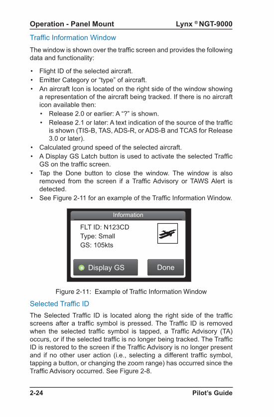
Lynx ® NGT-9000
Pilot’s Guide2-24
Operation - Panel Mount
Traffic Information WindowThe window is shown over the traffic screen and provides the following data and functionality:
• Flight ID of the selected aircraft.• Emitter Category or “type” of aircraft. • An aircraft Icon is located on the right side of the window showing
a representation of the aircraft being tracked. If there is no aircraft icon available then:• Release 2.0 or earlier: A “?” is shown. • Release 2.1 or later: A text indication of the source of the traffic
is shown (TIS-B, TAS, ADS-R, or ADS-B and TCAS for Release 3.0 or later).
• Calculated ground speed of the selected aircraft.• A Display GS Latch button is used to activate the selected Traffic
GS on the traffic screen. • Tap the Done button to close the window. The window is also
removed from the screen if a Traffic Advisory or TAWS Alert is detected.
• See Figure 2-11 for an example of the Traffic Information Window.
Figure 2-11: Example of Traffic Information Window
Display GS Done
Information
FLT ID: N123CDType: SmallGS: 105kts
Selected Traffic IDThe Selected Traffic ID is located along the right side of the traffic screens after a traffic symbol is pressed. The Traffic ID is removed when the selected traffic symbol is tapped, a Traffic Advisory (TA) occurs, or if the selected traffic is no longer being tracked. The Traffic ID is restored to the screen if the Traffic Advisory is no longer present and if no other user action (i.e., selecting a different traffic symbol, tapping a button, or changing the zoom range) has occurred since the Traffic Advisory occurred. See Figure 2-8.

Lynx ® NGT-9000
Pilot’s Guide 2-25
Operation - Panel Mount
AURAL ANNOUNCEMENTS
Aural Traffic Advisories are provided by the optional TAS, TCAS, or ATAS function. “Traffic, Traffic” (or “Traffic”& aircraft clock position Release 2.0 or later) is a normal aural component of a traffic advisory is announced once over the cockpit speakers or headset when a TA is first detected. This aural announcement can be silenced using the audio acknowledge buttons. It may also be delayed if a higher priority alert is occurring at the time of the alert.Do not rely solely on the aural alerts for intruder aircraft information. Use the display to view the latest TA and aircraft information. Units with the TAS/TCAS feature Aural announcements are only made when the TA first occurs and may be silenced by the audio acknowledge button. Units with the ATAS feature have 2 alert level or “zones”. The Protected Airspace Zone (PAZ) and the Collision Airspace Zone (CAZ). Alerts may be generated for both of these alert zones so one TA aircraft may generate 2 alerts for ATAS.
Selected Traffic GS
The Selected Traffic GS (if configured) is located along the right side of both screens (under the selected traffic ID) after a traffic symbol is pressed. The Traffic GS is removed when the selected traffic symbol is tapped, a Traffic Advisory (TA) occurs, or if the selected traffic is no longer being tracked. The Traffic GS is restored to the screen if the Traffic Advisory is no longer present and if no other user action (i.e., selecting a different traffic symbol, tapping a button, or changing the zoom range) has occurred since the Traffic Advisory occurred. See Figure 2-8.
True Track (TRK)This indication is located on the lower right side of the traffic screen when a heading source is configured as an input, but the heading source is not operational.

Lynx ® NGT-9000
Pilot’s Guide2-26
Operation - Panel Mount
Extended Audio CalloutsThe Extended Audio Callouts is a configuration option that adds relative bearing, relative altitude (when available) and range to the intruder information announced as well as the normal alert (or relative altitude, range, and vertical sense for Release 2.0 or later) It is available to the TAS, TCAS, and ATAS functions.
• The relative bearing provides a clock bearing (e.g. “12 O’clock).
• The relative altitude (if available) announces either “High” if > 50 ft or “Low” if < -50 ft or “Same Altitude” if > -50 ft and < 50 ft of own altitude).
• The range in nautical miles is either slant range if TA is Altitude Reporting or flat range if TA is not Altitude Reporting (NAR).
• Release 2.0 or later:
• The Vertical Sense (if available) announces either:• “Climbing” if vertical climb rate is >= 500 fpm• “Descending” if vertical descent rate is >= 500 fpm• “Level” if vertical rate is < 500 fpm
Some examples of extended audio alerts are: • Release 1 “Traffic, Traffic, 10 O’clock high, 5 miles” This
aural announcement is for an intruder at a relative bearing of 300 degrees, at a higher altitude, 5 miles away.
• Release 2.0 or later “Traffic, 6 O’clock same altitude, less than a mile, level” This aural announcement is for an intruder at a relative bearing of 180 degrees, at the same altitude, less than a mile away, flying level.
AUDIO MUTINGAudio may be silenced in the following ways:
• Some Aircraft may be equipped with an external CAWS or TAWS (i.e., stall warning > Terrain Alert > Traffic Avoidance) type system that has higher priority audio annunciation that will delay traffic or terrain alerts.
• (Release 2.0 or later) Press the external mounted Audio Acknowledge Button (located on the yoke or panel) to silence the current aural announcement.

Lynx ® NGT-9000
Pilot’s Guide 2-27
Operation - Panel Mount
Automatic Dependent Surveillance - Broadcast (ADS-B)ADS-B improves situational awareness and flight safety by providing real time traffic information. The ADS-B In function is used to receive ground station supported TIS-B and ADS-R traffic, and direct communication with nearby like equipped aircraft (with Mode S or UAT). The ADS-B Out (1090ES) function is used to periodically broadcast (without interrogation) information about the aircraft that includes aircraft identification, position, altitude, velocity and other aircraft status information.
• ADS-B does NOT relieve the pilot of responsibility to “see-and-avoid” other aircraft.
• No avoidance maneuvers are provided for, nor authorized, as a direct result of a ADS-B other aircraft being displayed in the cockpit. Avoidance maneuvers must be based on visually acquiring the target
• The traffic display shows the relative position of ADS-B or standard traffic using text, shapes, and colors. ADS-B also provides similar information on ADS-B equipped ground vehicles.
• The effective surveillance range is 60 nmi (ADS-B In) The passive-mode surveillance range is 160 nmi and maintains report messages for a minimum of 200 1090ES ADS-B participants and 300 UAT ADS-B participants simultaneously. To reduce display clutter a set number of other aircraft of the highest priority other aircraft are displayed at a time.
DETAILS ON TRAFFIC OPERATION
Operational details for ADS-B, ATAS, ADS-R, and TIS-B are provided below. This information is being provided to help in the understanding of the Lynx NGT-9000 ADS-B traffic system .
• (Release 2.0 or later) Tap the Acknowledge Button on the Lynx NGT-9000 traffic display to silence the current aural announcement.
• (Release 2.1 or later) Configuration Options “TAS Ground Filtering”: (1-standard) Aural traffic alerts from TAS functions are suppressed when the ownship is at or below 1700 ft AGL and the intruder is below 380ft AGL (above ground level). (2-alternate) Aural Traffic Alerts suppressed when the ownship is at or below 1700 ft AGL and the intruder is below 5ft AGL (instead of 380 ft AGL). For Release 3.0 this configuration also applies for TCAS.
• No traffic alerts are generated for aircraft that are on-ground even though ground-based symbols are displayed by ADS-B.

Lynx ® NGT-9000
Pilot’s Guide2-28
Operation - Panel Mount
Automatic Dependent Surveillance – Re-broadcast (ADS-R)
ADS-R is a ground based broadcast service that repeats ADS-B messages from one link (1090 MHz or 978 MHz) to the other link for aircraft with ADS-B In.
• ADS-R does NOT relieve the pilot of responsibility to “see-and-avoid” other aircraft.
• No avoidance maneuvers are provided for, nor authorized, as a direct result of a ADS-R other aircraft being displayed in the cockpit. Avoidance maneuvers must be based on visually acquiring the target.
• The actual availability of services depends upon both the availability of a ground station to support ADS-R source data and aircraft being within range of the ground station.
• ADS-R transmissions are updated at least every 2 seconds on the surface, 5 seconds in the terminal area, and 10 seconds in the en-route airspace.
• Other aircraft are provided by the ground station if within a 15 nm horizontal range and +/-5,000 ft of altitude of the receiving aircraft. ADS-B equipped ground aircraft and vehicles are not displayed to airborne aircraft.
• An aircraft on the ground receiving ADS-R is provided both ground aircraft and vehicles as well as airborne other aircraft within 5nm and 2,000 ft above ground level of the airport reference point.
• Receiving aircraft must be in both ATC radar coverage and ground based transceiver (GBT) coverage in a given area to receive ADS-R service in that area. ADS-R range is larger than the TIS-B range of 24,000 ft above station.

Lynx ® NGT-9000
Pilot’s Guide 2-29
Operation - Panel Mount
Traffic Information Service - Broadcast (TIS-B)TIS-B is the broadcast from Ground Radio Stations of ATC derived traffic information to ADS-B equipped aircraft.
• The actual availability of TIS-B source data depends upon the availability of ground-based radar.
• Receiving aircraft must be in both ATC radar coverage and ground based transceiver (GBT) coverage in a given area to receive TIS-B service in that area. When ownship is above 24,000 ft, the ground station will no longer provide TIS-B service. (Targets will be provided up to 27,500 ft when ownship is at 24,000 ft)
• Other aircraft are provided by the ground station if within a 15nm horizontal range and +/-3,500 ft of altitude of the receiving aircraft. ADS-B equipped ground aircraft and vehicles are not displayed to airborne aircraft.
• Aircraft not equipped with a transponder, or equipped with a Mode A only transponder are not part of the TIS-B data and will not be seen on the traffic display.
• The ground station will not provide display information for Mode C and Mode S transponder equipped aircraft that do not provide altitude information.
• An aircraft on the ground receiving TIS-B is provided both ground aircraft and vehicles as well as airborne other aircraft within 5nm and 2,000 ft above ground level of the airport reference point.
• The TIS-B service is intended to improve the pilot’s ability to visually see traffic in the air and on the airport surface so that pilots can more effectively apply traditional “see-and-avoid” techniques.
• TIS-B does NOT relieve the pilot of responsibility to “see-and-avoid” other aircraft.
• No avoidance maneuvers are provided for, nor authorized, as a direct result of a TIS-B other aircraft being displayed in the cockpit. Avoidance maneuvers must be based on visually acquiring the target.

Lynx ® NGT-9000
Pilot’s Guide2-30
Operation - Panel Mount
TRAFFIC ALERTING
The Lynx NGT-9000 has three traffic alerting methods available.
• The Traffic Advisory System (TAS) and Traffic Alert and Collision Avoidance System (TCAS) options require a specific model of the Lynx NGT-9000. TAS/TCAS is an active traffic system that interrogates nearby aircraft transponders. The TCAS option is available for Release 3.0 or later.
• The ADS-B Traffic Advisory System (ATAS) option provides traffic alerts using ADS-B In (ADS-B, ADS-R, and TIS-B) traffic information. This feature is available for Release 2.0 or later.
Each system alerts the flight crew aurally and visually which assists the pilot in the visual acquisition of aircraft that may represent a danger. ATAS and TAS/TCAS may operate (if installed) at the same time with traffic information being correlated by the unit. ATAS alerting has the highest priority if using ADS-B or ADS-R, but TAS/TCAS has priority if ATAS is using TIS-B.
Each of the traffic alerting systems share the following operational details:
• Traffic information is graphically displayed on the NGT-9000+ or alternate display.
• The system display shows the relative position of traffic using text, shapes and colors.
• The system uses an audio output that announces Traffic Advisory and relative bearing, relative altitude and range.
• Alerts are generated first from ADS-B data, then by TAS/TCAS data (if aircraft is equipped with the NGT-9000+), and lastly by TIS-B data (if available). ATAS alerting is superimposed over TAS/TCAS alerting providing suppression of nuisance TAS/TCAS alerts. If other aircraft are being tracked only by TAS/TCAS, then TAS/TCAS alerting is used.
• An optional discrete output (traffic alert lamp) may be used to indicate a traffic advisory (TA) has been detected.
• All other aircraft that may be displayed that do not meet the criteria of a TA or PA are classified as Other Traffic (OT).

Lynx ® NGT-9000
Pilot’s Guide 2-31
Operation - Panel Mount
ADS-B Traffic Advisory System (ATAS)
The ADS-B Traffic Advisory System (ATAS) aurally and visually alerts the flight crew to nearby aircraft and assists in the visual acquisition of aircraft that may present a danger. See Figure 2-12.
ATAS is a dynamic system that uses two protected zones of airspace (i.e. CAZ, PAZ) around ownship to generate alerts. The Collision Airspace Zone (CAZ) has a constant detection zone. The Protected Airspace Zone (PAZ) predicts the path of intruder aircraft and alerts the flight crew that the intruder aircraft will enter the path of the ownship. See Figure 2-13 for an example.
• The dimensions of CAZ is fixed at 500 ft. horizontal radius and +/- 200 ft. relative altitude.
• The dimension of PAZ is dependent on closure rate. The PAZ dimension decreases as closure rate decreases with a minimum 750 ft. horizontal radius and +/- 300 ft. (Sensitivity A) or +/- 500 ft. (Sensitivity B) relative altitude.
• The tracking of aircraft traffic is in a cylindrical volume centered on own aircraft with a maximum radius of 20 nmi and extending 10,000 ft. above and 10,000 ft. below ownship.
• ATAS will track up to 60 intruder aircraft simultaneously.• A Traffic Advisory (TA), Proximate Advisory (PA), and Other Traffic
(OT) are issued only when the ownship aircraft status is in air. • Aircraft that are within a range of 6 nmi of ownship with a vertical
distance of +/- 1200 ft (if altitude is reporting) are identified as a Proximate Advisory (PA).
• For Software earlier then 3.0 Sensitivity Level A is an area within 10 nm of an airport which is also identified as the Airport environment or terminal area. The Lynx NGT-9000 defines an airport environment as an airport with a runway with at least 500 ft of hard surface. Any airport without those specifications (e.g. runway with grass or <500ft long) will not be shown on the traffic screen, but will be categorized as a sensitivity level A.
• For Software 3.0 and later Sensitivity Level A uses ownship AGL altitude when ownship is < 2,000 AGL or < 120 knots, rather than airport elevation.
• Sensitivity Level B is the area outside the airport environment which is also identified as the enroute area.

Lynx ® NGT-9000
Pilot’s Guide2-32
Operation - Panel Mount
Sensitivity Level ASensitivity level A (terminal area) uses the following criteria for displaying a TA:
1. Ownship has a valid altitude < 2,000 ft. Above Ground Level (AGL) or an invalid ownship altitude with a valid ground speed of < 120 kts.
2. Alerts at least 12.5 seconds prior to Closest Point of Approach (CPA) within 750 ft. horizontally and +/- 300 ft. vertically.
3. No alerts are issued if the intruder aircraft CPA is >0.5 nm horizontally or 500 ft. vertically.
Sensitivity Level BSensitivity level B (enroute area) uses the following criteria for displaying a TA:
1. Ownship has a valid altitude > 2,000 ft. Above Ground Level (AGL).
2. Alerts at least 12.5 seconds prior to Closest Point of Approach (CPA) within 750 ft. horizontally and +/- 500 ft. vertically.
3. No alerts are issued if the intruder aircraft CPA is >2.0 nm horizontally or 850 ft. vertically.
ATAS Sensitivity Levels
The A or B sensitivity level is used to determine when to display a TA within Protected Airspace Zone (PAZ). Having two sensitivity levels allows the unit to reduce the number of nuisance TAs during takeoff and landing (Sensitivity Level A), and to maximize the detection of TAs during the cruise phase of flight (Sensitivity Level B).
The following information provides details for issuing traffic alerts. See Figure 2-13.
• A TA is issued when an intruder aircraft comes within the CAZ area of the ownship.
• A TA is issued at least 35 seconds prior to Closest Point of Approach (CPA) when no acceleration in intruder and ownship.
• A TA is issued at least 12.5 seconds prior to the CPA with intruder aircraft when intruder aircraft are within Sensitivity Levels A and B of the ownship.
• A TA symbol remains on the screen for at least 8 seconds unless the respective track is terminated.

Lynx ® NGT-9000
Pilot’s Guide 2-33
Operation - Panel Mount
Figure 2-12: ATAS Traffic Display and Traffic Zone Graphic
CPA = Closest Point of ApproachCAZ = Collision Airspace ZonePAZ = Protected Airspace Zone
Not To Scale
Ownship
(CAZ) 500 ft
(PAZ) 750 ft
(PAZ) 750 ft
+/-10,000 ft
Sensitivity Level B
6 nm
Trac
k
Predicted
Path
20 nm
CAZ +/-200 ft
PAZ +/- 300 ft
PAZ +/- 500 ft
+/- 1,200 ft
– Traffic Advisory (TA) Non-directional)
– Proximity Advisory (PA) Non-directional)
– Other Traffic (OT) Non-directional)
– Traffic Advisory (TA) directional)
– Proximity Advisory (PA) directional)
– Other Traffic (OT) directional)
Sensitivity Level A
Sensitivity Level A and B Alert atleast 12.5 seconds to CPA
Area outside of Sensitivity Level Aand B Alert at least 35 seconds toCPA when no acceleration inintruder aircraft and ownship.
A TA is issued when the predictedpath of an intruder aircraft entersthe ownship PAZ or CAZ area.
IntruderAircraft
IntruderAircraft

Lynx ® NGT-9000
Pilot’s Guide2-34
Operation - Panel Mount
Figure 2-13:Example of ATAS Predicted Intruder Path
Time = 0s Time = +15s Time = +35s
IntruderAircraft
1
IntruderAircraft
2
Ownship
PAZ
CAZ
PAZ dimension decreasesas closure rate decreasesThe PAZ is actuallycalculated for the entirelength of the trajectory.
Predicted Path
Predicted PAZ penetrationresults in an alertbeginning with Time = 0.
Predicted pathresults in no PAZpenetration. Noalert issued.
T = TimeFuture Z
Lynx ® NGT-9000
Pilot’s Guide 2-35
Operation - Panel Mount
Traffic Advisory System (TAS) and Traffic Alert and Collision Avoidance System (TCAS)
TAS and TCAS is an active system that interrogates transponders (aircraft to aircraft) in the surrounding airspace similar to ground based radar. When replies to these active interrogations are received, the responding aircraft’s range, altitude, and closure rates are computed to plot traffic location and predict collision threats. The NGT-9000+ or NGT-9000R+ alerts the flight crew to nearby transponder equipped aircraft and assists the pilot in the visual acquisition of aircraft that may represent a danger. Table 2-3 summarizes the criteria necessary to display a traffic advisory. Figure 2-14 shows the TAS/TCAS Traffic Zone Graphic.
• The effective active-mode surveillance range is 35 nmi and track 35 ATCRBS intruders simultaneously with the other aircraft bearing relative to the nose of own aircraft.
• The tracking of other aircraft is in a cylindrical volume centered on own aircraft with a maximum radius of 35 nmi and extending 10,000 ft above and 10,000 ft below own aircraft.
• A TA symbol remains on the screen for at least 8 seconds, even if the intruder aircraft no longer meets the TA criteria, as long as the Lynx NGT-9000 continues to track the aircraft.
TAS/TCAS Sensitivity Levels
The A or B sensitivity level is used to determine when to display a TA. Having two sensitivity levels allows the unit to reduce the number of nuisance TAs during takeoff and landing (Sensitivity Level A), and to maximize the detection of TAs during the cruise phase of flight (Sensitivity Level B).

Lynx ® NGT-9000
Pilot’s Guide2-36
Operation - Panel Mount
Sensitivity Level A
Sensitivity level A (terminal area) consists of two criteria for displaying a TA:
1. The intruder aircraft enters into an area of airspace surrounding ownship defined by a 0.2 nmi horizontal radius and a height of ±600 ft from ownship
2. The intruder aircraft approaches ownship on a course that will intercept ownship within 15 or 20 seconds (within 15 seconds for a non-altitude reporting intruder aircraft; within 20 seconds for an altitude reporting intruder aircraft).
The unit uses sensitivity level A in the following situations (corresponds to numbers 1, 2, 7, and 8 in Table 2-3):
1. For Software earlier then 3.0 Sensitivity Ownship has a valid AGL (above ground level) altitude and is below 2,000 ft AGL. Note - The unit calculates height above terrain using GPS Altitude and nearest airport elevation. For Software 3.0 and later Sensitivity Level A uses ownship AGL altitude when ownship is < 2,000 AGL or < 120 knots, rather than airport elevation.
2. Ownship AGL Altitude is Invalid, and ownship ground speed is available or is less than 120 knots.
Sensitivity Level B
Sensitivity level B (enroute area) consists of two criteria for displaying a TA:
1. The intruder aircraft enters into an area of airspace surrounding ownship defined by a 0.55 nmi horizontal radius and a height of ±800 ft from ownship.
2. The intruder aircraft approaches ownship on a course that intercepts ownship within 20 or 30 seconds (within 20 seconds for a non-altitude reporting intruder aircraft; within 30 seconds for an altitude reporting intruder aircraft).
The unit uses sensitivity level B when the criteria for Sensitivity Level A has not been met. (Corresponds to numbers 3, 4, 5 and 6 in Table 4-1).

Lynx ® NGT-9000
Pilot’s Guide 2-37
Operation - Panel Mount
Table 2-3: TAS /TCAS Traffic Advisory Situations
NO. OWN SHIP ALT
OWN SHIP GND SPEED
OTHER AIRCRAFT IS DETECTED
1Below 2000 ft AGL
Within a 0.2 nmi horizontal radius and a +/- 600 ft relative altitude.
2 Within 15-20 sec of CPA *
3Above 2000 ft AGL
Within a 0.55 nmi horizontal radius and a +/- 800 ft relative altitude.
4 Within 20-30 sec of CPA *
5
Has in-valid AGL Altitude
Available and > to 120 knots
Within a 0.55 nmi horizontal radius and a +/- 800 ft relative altitude.
6 Within 20-30 sec of CPA *
7 Available and < 120 knots
Within a 0.2 nmi horizontal radius and a +/- 600 ft relative altitude.
8 Within 15-20 sec of CPA *
Sensitivity Level A Sensitivity Level B
* CPA means Closest Point of Approach** Ground speed is not available whenever the GPS navigation information is not available.
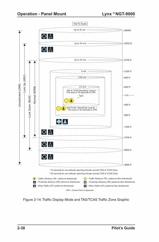
Lynx ® NGT-9000
Pilot’s Guide2-38
Operation - Panel Mount
Figure 2-14: Traffic Display Mode and TAS/TCAS Traffic Zone Graphic
0.2 nmi
0.55 nmi
+2700 ft
–2700 ft
+9000 ft
–9000 ft
–9900 ft
*15 seconds for non-altitude reporting intruder aircraft (TAS & TCAS Only)
Not To Scale
+800 ft
+1200 ft
–800 ft
–1200 ft
+600 ft
–600 ft
Look
Dow
n (B
LW)
Look
Up
(AB
V)
Nor
mal
(N
RM
)
0 ft
**20 seconds for non-altitude reporting intruder aircraft (TAS & TCAS Only)
Unr
estr
icte
d (U
NR
)
+9900ftUp to 35 nmi
4 nmi
– Traffic Advisory (TA) (airborne Non-directional)
– Proximity Advisory (PA) (airborne Non-directional)
– Other Traffic (OT) (airborne Non-directional)
CPA = Closest Point of Approach
– Traffic Advisory (TA) (airborne directional)
– Proximity Advisory (PA) (airborne directional)
– Other Traffic (OT) (airborne directional)
TAS & TCAS Sensitivity Level A *This area or 20 seconds to CPA
TAS/TCAS I Sensitivity Level B **This area or 30 seconds to CPA
Up to 35 nmi
Up to 35 nmi

Lynx ® NGT-9000
Pilot’s Guide 2-39
Operation - Panel Mount
Other Aircraft Ground FilteringIf the ownship is at or below 1700 ft AGL, the traffic Advisory system (TAS) or TCAS will not display or calculate alerts for other aircraft which are determined to be on ground (not airborne). Intruders determined to be below 380 ft AGL are considered to be on ground and will not be output with the TAS/TCAS active traffic output.
(Release 2.1 or later) Configuration Option “Ground Filtering Altitude”: The on ground (alternate) determination can be set for 5ft (instead of 380 ft AGL).
NOTESince the Lynx NGT-9000 also receives ADS-B traffic information, aircraft no longer under TAS/TCAS surveillance may still be displayed based on the received ADS-B traffic data.
Interference LimitingTo assure that interference effects from active TAS/TCAS equipment are kept to a minimum, the FAA requires TAS/TCAS equipment to “interference limit,” i.e. reduce its transmit power, when it is operating in congested airspace. This limiting function is based on the number of TCAS interrogators detected via Mode S broadcast reception and the reply rate of the aircraft transponder. Interference limiting reduces the effective surveillance range of the TAS/TCAS equipment and is independent of the display range selected.
NOTES1. Selected display range has no affect on the surveillance
range of the TAS/TCAS.2. This interference limiting function is for active TAS/
TCAS and does not affect the range at which ADS-B reporting traffic will be received. It also does not limit the range at which the Lynx NGT-9000 ADS-B output will be received by other aircraft.
3. Dual TAS/TCAS and ATAS operation where aircraft tracked by both alerting systems will alert based on the ATAS system. Aircraft tracked only by TAS/TCAS in this scenario will still alert according to the TAS/TCAS rules.

Lynx ® NGT-9000
Pilot’s Guide2-40
Operation - Panel Mount
WEATHER OPERATION
The Lynx NGT-9000 provides weather information using data provided by the Flight Information Service - Broadcast (FIS-B). The FIS-B service is available only from a ground station that is in range to aircraft equipped with UAT receivers.
The FIS-B broadcast provides a graphical and textual display of weather and aeronautical information. This information is provided on three different application screens named below as “Graphical Weather Application”, “Graphic Winds and Temps Application”, and Textual Application”. This information is detailed below. The map orientation is typically shown as north up.
Alternate weather displays and PEDs may show the weather data differently than what is shown in this pilot’s guide. Refer to the display operation manual or PED application information for details.
Details on Flight Information Service - Broadcast (FIS-B)
FIS−B is a ground broadcast service provided through the ADS−B Services network over the 978 MHz UAT data link. By using FIS−B for orientation and information, the usefulness of information received from official sources may be enhanced, but the user should be alert and understand any limitations associated with individual data.
The weather data listed in Table 2-4 is available on specific application screens as detailed below.
FIS−B augments the traditional ATC/FSS/ AOCC services by providing additional information and in some cases the advantage of being displayed graphically. The data provided by FIS−B is for information only and does not meet the safety and regulatory requirements of official weather data.

Lynx ® NGT-9000
Pilot’s Guide 2-41
Operation - Panel Mount
PRODUCT DESCRIPTION
AIRMET Text/graphical report - Airmens Meteorological Infor-mation is a weather advisory issued by a meteorolog-ical watch office. It provides an advisory of potentially hazardous condition exists for low-level aircraft and/or aircraft with limited capability. Compared to SIG-METs, AIRMETs cover less severe weather: moder-ate turbulence and icing, surface winds of 30 knots, or widespread restricted visibility.
METAR Text reports − Surface meteorological data. Includes airport identifier, time of observation, wind, visibility, runway visual range, present weather phenomena, sky conditions, temperature, dew point, and altimeter setting. Remarks may be appended to the end.
NEXRAD, Regional
Graphical report - Next-Generation Radar is a na-tionwide network of high resolution Doppler weather radars, which detect precipitation and atmospheric movement or wind. It returns data which when pro-cessed can be displayed in a mosaic map which shows patterns of precipitation and its movement. The “Regional NEXRAD” FIS-B product is a com-posite of available NEXRAD radar imagery in a local area, showing a more detailed image than the “CO-NUS NEXRAD” product.
NEXRAD, CONUS
Graphical report - The “CONUS NEXRAD” FIS-B product is a summary composite of available NEX-RAD radar imagery across the 48 states.
NOTAM Text/graphical report - Notice To Airmen is creat-ed and transmitted by government agencies under guidelines specified by Annex 15: Aeronautical Infor-mation Services of the Convention on International Civil Aviation. A NOTAM is filed with an aviation au-thority to alert aircraft pilots of any hazards En Route or at a specific location. The FIS-B NOTAM product consists of NOTAM-Ds and NOTAM-FDCs (including TFRs).
Table 2-4: Description of FIS-B Available Information

Lynx ® NGT-9000
Pilot’s Guide2-42
Operation - Panel Mount
PRODUCT DESCRIPTION
SIGMET Text/graphical report − Potentially hazardous en route phenomena such as thunderstorms and hail, turbulence, icing, sand and dust storms, tropical cy-clones, and volcanic ash in an area affecting 3,000 square miles or an area deemed to have a significant effect on safety of aircraft operations.
SIGMET, Convective
Text/graphical report - hazardous thunderstorms and related phenomena across Continental US. Convective SIGMETs issued for thunderstorms and related phenomena do not include with thun-derstorms such as turbulence, icing, low level wind shear and IFR conditions.
TAF Text report - Terminal Aerodrome Forecast is a format for reporting aviation weather forecast information. Generally a TAF is a 9- or 12-hour forecast, though some TAFs can cover an 18- or 24-hour period. TAFs complement and use similar encoding to METAR reports. They are produced by a human forecaster based on the ground. For this reason there are fewer TAF locations than there are METARs. TAFs can be more accurate than Numerical Weather Forecasts, since they take into account local, small scale, geo-graphic effects.
Winds and Tempera-tures Aloft
Graphical report - Winds and Temperature Aloft Fore-cast is forecast for specific atmospheric conditions in terms of wind and temperature in a specific altitude measured mostly in feet (ft) above mean sea level (MSL). The forecast is specifically used for aviation purposes.
Table 2-4: Description of FIS-B Available Information (continued)

Lynx ® NGT-9000
Pilot’s Guide 2-43
Operation - Panel Mount
FIS-B No Coverage IndicatorWhen configured to be enabled the indicator is located at the bottom center of the screen and is shown when No FIS-B data is available in the area (i.e. out of range of a ADS-B ground station). See Figure 2-16.
• The indicator is also shown if a problem exists with the NGT-9000 System. See the troubleshooting section.
When configured to be disabled, the Winds & Temps and FIS-B textual data screens are deactivated and the FIS-B No Coverage Indicator is disabled.
Figure 2-15: FIS Button
Auto FIS-B Function
When configured for Auto FIS-B, the Winds & Temps and FIS-B textual data screens are initially deactivated and the FIS-B No Coverage Indicator is disabled. The Winds & Temps and FIS-B textual data screens are activated and the FIS-B No Coverage Indicator enabled when FIS-B weather messages have been detected. When FIS-B is in operation a button is present on the screen that is used to disable/enable FIS-B function. See Figure 2-15.

Lynx ® NGT-9000
Pilot’s Guide2-44
Operation - Panel Mount
Figure 2-16: Weather Map
FIS-B Graphical Weather ApplicationThe Graphical Weather Application is located in the second screen position (or third screen position when TAWS is enabled, Release 2.0 or later) as indicated by the Application Indicator. The Graphic Application is a simplified moving map with depiction of ownship and the ability to selectively overlay graphical FIS-B products such as, NEXRAD, METAR, and SIGMET. See Figure 2-16.
Traffic Button
ZoomIn
Options Button
ZoomOut
InformationButton
Display RangeIndicator
Selected AirportID Indicator
NorthIndicator
TimeStamp
AirportSymbol
SelectedSymbol
OrientationButton
No CoverageIndicator
Map ElementsFIS-B weather products are overlaid on the map. The viewing of weather products is controlled by the declutter range selected on the Options Screen.
• Tap to select Product overlaid map elements.• The selected map elements are highlighted in a yellow outline. • A tap of an empty area of the map de-selects the map element.• Only one map element can be selected at a time and may be
selected when panning is active or not. • The map is normally centered on the ownship symbol when
panning is not activated. When panning is active the viewing area is repositioned to that selected by the pilot.
• The directional ownship symbol is a white triangle that is a reference point that corresponds to the ownship position.
• The ownship symbol is a white circle if direction data is not known.

Lynx ® NGT-9000
Pilot’s Guide 2-45
Operation - Panel Mount
• The land masses are black. Bodies of water are dark blue. Depiction of NEXRAD weather radar data is overlaid on the map. Map areas where NEXRAD data has not been received are indicated using a gray semi-transparent graphical overlay. This will cause land masses to appear grey and water to appear light blue when no graphical NEXRAD data is available.
• Country and State borders are solid light gray lines. • Major roads are depicted as solid gray lines for display ranges less
than or equal to 200 nm. • Cities are shown on the map in small white text centered on the
cities location. The display ranges of cities are dependent on the size of the city as follows: Large and medium sized cities are shown at less than or equal to 200 nm. Small cities are shown at less than or equal to 50 nm.
• The symbol for the different types of airports are described in Table 2-5. Soft surfaced airports are shown at display ranges less than or equal to 10 nm. Hard surfaced small airports are shown at display ranges less than or equal to 20 nm. Hard surfaced large airports are shown at display ranges less than or equal to 200 nm.
Information Button (i)The Information button is shown on the screen, located on the right side of the screen, after a map element is selected. The button is gray in color and labeled with an “i” icon. Tap the button to show the Weather Map Text screen on the left side of the screen.
TFR Map ElementsTemporary Flight Restrictions are displayed on the map as a solid red line. A TFR is shown as a solid orange line up to 12 hours prior to the effective date and time of the TFR.
AIRMET and SIGMET Map ElementsAIRMET and SIGMET are weather advisories with concise descriptions of weather conditions in an area. The AIRMET are used for less severe weather then the SIGMET. The type and graphic description are detailed below:
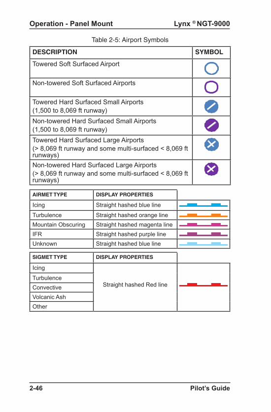
Lynx ® NGT-9000
Pilot’s Guide2-46
Operation - Panel Mount
Table 2-5: Airport Symbols
DESCRIPTION SYMBOL
Towered Soft Surfaced Airport
Non-towered Soft Surfaced Airports
Towered Hard Surfaced Small Airports(1,500 to 8,069 ft runway)Non-towered Hard Surfaced Small Airports(1,500 to 8,069 ft runway)Towered Hard Surfaced Large Airports(> 8,069 ft runway and some multi-surfaced < 8,069 ft runways)Non-towered Hard Surfaced Large Airports(> 8,069 ft runway and some multi-surfaced < 8,069 ft runways)
AIRMET TYPE DISPLAY PROPERTIES
Icing Straight hashed blue line
Turbulence Straight hashed orange lineMountain Obscuring Straight hashed magenta lineIFR Straight hashed purple lineUnknown Straight hashed blue line
SIGMET TYPE DISPLAY PROPERTIES
Icing
Straight hashed Red lineTurbulenceConvectiveVolcanic AshOther

Lynx ® NGT-9000
Pilot’s Guide 2-47
Operation - Panel Mount
REGIONAL NEXRAD Map ElementsNEXRAD provides data on precipitation and its intensity in the form of a composite mosaic image. See Figure 2-17. NEXRAD information extends to approximately a 75 nm radius of the ownship, and is only updated every 5 minutes. Note - Freezing precipitation colors (pink/blue) are not provided.
The age of the NEXRAD data is shown in the lower left corner of the screen with yellow text. The time stamp is labeled with “RDR” and “min”. Dashes replace the time stamp when no NEXRAD image data is available. (The actual age of the data can be 0 to 20 minutes older than indicated.)
CONUS NEXRAD Map ElementsCONUS information covers the Continental United States. It is only updated every 15 minutes. See Panning paragraph on page 2-55 for more information.
FLIGHT RULES DISPLAY PROPERTIES
VFR Filled cyan circleMVFR Filled green circle
IFR Filled yellow circleLIFR Filled magenta circle
Unknown Filled grey circle
Figure 2-17: Example of NEXRAD Weather Map
METAR Map ElementsMETAR is a report of weather conditions at airports represented graphically and consists of the FAA Flight Rules and Weather Conditions. The flight rules icons shows the FAA flight rules for each airport based on the visibility and cloud cover conditions. The weather conditions icons indicates the weather conditions at each airport based on precipitation, winds, and visual obstructions. The type and graphic description are detailed below:

Lynx ® NGT-9000
Pilot’s Guide2-48
Operation - Panel Mount
Traffic ButtonThis button is located on the far left side of the screen and is labeled “TFC” with a left facing triangle. Tap the button to return to the Traffic Application screen.
Zoom ButtonsZoom In (+) and Zoom Out (-) buttons are located on the bottom of screen. The buttons are used to change the display range shown on the display. Display range options for the Graphic Application screen are 10 (minimum), 20, 50, 100, 200, 400, and 800 (maximum).
Display Range IndicatorThis indication is a readout of the selected display range and is located in the lower right corner of the display.
PanningPress and hold an area of the screen that is not a button for 1 second to activate the Panning function. Drag across the map to move the map in that direction. Tap the Cancel Pan button to inactivate the panning function.
North IndicatorThis indication is a white/green arrow located in the lower right corner of the display. The indicator points to the top of the display when the application is oriented north up and points true north when the application is oriented track up.
Airport ID IndicatorThe airport ID is shown on the screen, located below the Information button, after an airport map element is selected.
Orientation ButtonThis toggle button is located on the left side of the screen is labeled “Map”. The button has two selections “NRTH” which is north up and “TRK” which is track up. The lower half of the button shows the current map orientation in green text. The north up orientation has the ownship position in the center of the map screen.The track up orientation has the ownship centered horizontally but moved down to the lower one third of the screen (this orientation provides a longer look ahead in the direction of travel).The map defaults to North Up orientation if ownship position data is not valid.

Lynx ® NGT-9000
Pilot’s Guide 2-49
Operation - Panel Mount
Map Options ButtonThe gear shaped Options Button is located in the upper right corner of the map screen. Tapping the button opens the Options screen that has three latch buttons located on the bottom of the screen. These buttons are labeled ON/OFF, Declutter, and Done.
Tap the Done button to close the Options Screen.
On/Off Option ScreenThe ON/OFF screen has Toggle On/Off buttons for the FIS-B products and a Legend. A green LED indicates that the button and function is On. See Figure 2-18.
Weather Map Legend ScreenThe Legend screen is located on the left screen and is shown after the Legend button in the On/Off screen is tapped. The screen has a banner on the top of the screen above the left display area. See Figure 2-19.
BannerThe Banner is shown on the top of the screen having a gray background. The banner provides the following information: • Done button used to return to the previous screen.• Mode A squawk code indicator.• Reply “R” or Ident “ID” indicator shown to the right of the squawk
code when either function is active. • Current transponder operating mode status indicator with green
text. An amber “Fail” is shown when the transponder function has failed.
Figure 2-18: On/Off Options Screen

Lynx ® NGT-9000
Pilot’s Guide2-50
Operation - Panel Mount
Figure 2-19: Weather Map Legend Screen

Lynx ® NGT-9000
Pilot’s Guide 2-51
Operation - Panel Mount
Display AreaThe left display area is used to show the meaning of map elements provided by FIS-B products. It is identified with the label “Legend”. A scroll bar on the right side provides an indication that additional information can be seen by using an up/down drag action.
Declutter Option ScreenThe declutter screen has a banner at the top of the screen that is labeled with the declutter range scale from 10 to 800.
The Declutter setting sets the zoom range when a product is displayed/removed from the display.
The display area shows the declutter list of the different products (NEXRAD, METAR, TFR, AIRMET, and SIGMET). LED indicators show declutter ranges for each product. The selected list item is highlighted in white. Use the Zoom buttons to increase and decrease the layer range. Use a slide action to scroll up and down the product list. The example in Figure 2-20 would indicate that NEXRAD information would be displayed up to the 400 nm range.
Figure 2-20: Declutter Option Screen
Weather Map Text ScreenThe Weather Map Text is shown on the left screen after the Information button is tapped. The screen is removed from view when another application is activated on the right screen or if the selected map element is deselected. See Figure 2-21.
Display AreaThe left display area is used to show text report data from the selected map element.

Lynx ® NGT-9000
Pilot’s Guide2-52
Operation - Panel Mount
Figure 2-21: Weather Map Text Screen
BannerThe Banner is shown on the top of the left screen having a gray background The banner provides the following information:
• Done button used to remove the Weather Map Text screen and return the left side application screen.
• Mode A squawk code.• Reply “R” or Ident “ID” indicator shown to the right of the squawk
code when either function is active. • Current transponder operating mode status indicator with green
text. An amber “Fail” is shown when the transponder function has failed.
• Product Select button opens a Product Select window. The button is displayed only when the selected display element is an airport. See Figure 2-22.
If selected product text data report is not available, the display area indicates this by displaying the selected product with a “not available” message.
Product Select List Window The window shows a list of product types to select. Tapping the item will select the product type. Only one product type can be selected at a time. The available product are METAR, TAF, and NOTAM. Use a slide action to scroll the window up and down. Tap the item in the list to select. A selected item is indicated by a green indicator.
Tap the Done button to close the window and return to the Weather Map Text screen. The selected product will now be displayed on the Weather Map Text screen. If data for that product type is not available, the message “not available” is displayed.

Lynx ® NGT-9000
Pilot’s Guide 2-53
Operation - Panel Mount
Figure 2-22: Product Pick List Window
FIS-B Graphic Winds & Temp ApplicationThe Graphical Winds and Temperature Application is available on the right screen and is located in the third screen position (4th screen position when TAWS installed, Release 2.0 or later) as indicated by the Application Indicator. This application screen displays graphical wind and temperature aloft information obtained from FIS-B products. The aloft map orientation is shown as north up. See Figure 2-23.
Traffic ButtonThis button is located on the far left side of the screen and is labeled “TFC” with a left facing triangle. Tap the button to return to the Traffic Application screen.
Aloft ButtonThis button is located on the left side of the screen and is labeled “Aloft” with white text and the active selection labeled either “Wind” or “Temp” with green text. Tap the button to select the other screen function.
Figure 2-23: Aloft Map Screen
Ownship SymbolTraffic Button
ZoomIn
Cancel Pan Button
ZoomOut
Display RangeIndicator
Flight LevelSelection
NorthIndicator
TimeStamp
AloftButton
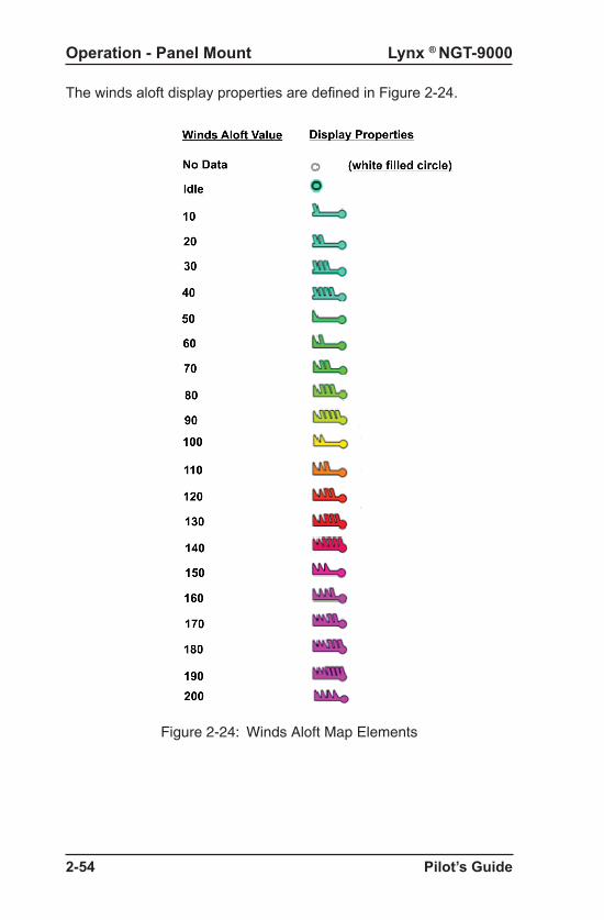
Lynx ® NGT-9000
Pilot’s Guide2-54
Operation - Panel Mount
The winds aloft display properties are defined in Figure 2-24.
Figure 2-24: Winds Aloft Map Elements

Lynx ® NGT-9000
Pilot’s Guide 2-55
Operation - Panel Mount
PanningPress and hold an area of the screen that is not a button for 1-3 seconds second to activate the Panning function. Drag across the map to move the map in that direction. Tap the “Cancel Pan” button to deactivate the panning function.
NEXRAD images may not appear after panning and zooming to a range 200 NM or less. Regional NEXRAD images displayed in panning mode (when display range is 200 NM or less) are based on the data received from nearby ground stations. Ground stations only provide Regional NEXRAD data for areas 150 to 250 NM around their location. Therefore, the Regional NEXRAD display image area is limited to an area around your aircraft position. No data available (gray overlay) is displayed when panning outside the available Regional NEXRAD data range. Zooming out to a range of 400nmi or later will switch to the CONUS NEXRAD display images (if available) and the depicted map includes areas of the continental US (CONUS).
Both Regional and CONUS NEXRAD are affected with the declutter “NEXRAD” setting. It is recommended that this declutter setting be set to 800NM.
Assuming both Regional and CONUS NEXRAD is available:
Zoom Range = 200NM or less: Regional NEXRAD data only is displayed.
Zoom Range = 400NM or later: CONUS NEXRAD data only is displayed.
Zoom ButtonsZoom In (+) and Zoom Out (-) buttons are located on the bottom of screen. The buttons are used to change the display range shown on the display. Display range options are 10, 20, 50, 100, 200, 400, and 800.
Issue Valid Time IndicationThis indicator is located at the bottom of the screen and is shown with green text when a valid time is shown. The text is shown with yellow text when the data is not valid or available.
Ownship Symbol The ownship is shown as a white triangle when heading or track is valid. When ownship direction source is not valid the ownship symbol is a white circle with a black inset.

Lynx ® NGT-9000
Pilot’s Guide2-56
Operation - Panel Mount
FIS-B Textual Application
The Textual Application is available on the right screen and is located in the fourth screen position as indicated by the Application Indicator. This application screen displays textual weather information products for selected airports provided by FIS-B. The products available are METAR, TAF, NOTAM. See Figure 2-25.
Display AreaThe display area is used to show text report data from the selected Product.
BannerThe banner is located above the display area. The banner contains buttons to return to the Traffic Application screen, open the Edit Airport ID window, open the Favorites Pick List window, and a button to open the Product Pick List window.
Figure 2-25: FIS-B Textual Application
Location: ABC1Day of month: 28Time: 19:15 UTCWind: 360 @ 6 ktsGusting to 0 ktsVisibility: 1 mile
FavoritesButton
TrafficButton
ProductButton
Display Area
Text ReportData
AirportButton
Banner
North IndicatorThis indication is a white/green arrow located in the lower right corner of the display. The indicator points to the top of the display when the application is oriented north up.
Flight Level SelectionThis is a vertical array of altitudes which is shown when the altitude is pressed. Selection is done by tapping the screen on the value desired. The values are in hundreds of feet.
When transitioning from one region to the other and the currently selected flight level is not supported in the new region, the selected flight level is reset to one that is supported.

Lynx ® NGT-9000
Pilot’s Guide 2-57
Operation - Panel Mount
Traffic ButtonThis button is located on the far left side of the banner and is labeled “TFC” with a left facing triangle. Tap the button to return to the Traffic Application screen.
Airport ButtonThis button is located to the right of the Traffic button and is labeled with the Selected Airport identifier. This information is also shown below in the display area. Tap the button to open the Edit Airport ID window.
Edit Airport ID WindowThis window is used to enter an Airport ID that is shown on the airport button and the display. See Figure 2-26.
• Use the keyboard to enter the three or four character alpha-numeric Airport ID in the airport edit box
• Tap the Cancel button to close the window without changing the current Airport ID.
• Tap the Add to Favorites button (star plus icon) to add the current Airport ID to the Favorites Pick List. The Favorites Pick List has maximum of 50 entries. The button is inhibited when the pick list has reached its maximum.
• Tap the Done button to close the window and set the selected airport ID.
If a selected airport is not found in the navigation database, an “Airport not found” message is shown in the display area.
Note - Some airports are FIS-B encoded with a 3-letter identifier and omitting the leading “K” or “P” in the entry may produce the desired airport.
Figure 2-26 Example of Edit Airport ID Window

Lynx ® NGT-9000
Pilot’s Guide2-58
Operation - Panel Mount
Figure 2-27: Example of Favorites Window
Favorites Button This button is labeled with a amber star icon. Tap the button to open the Favorites Pick List window.
Favorites Pick List WindowThis window is used to select a pre-saved Airport ID. See Figure 2-27.
• The Favorite Airports list is centered in the display area showing the list of airports set by the user via the add to favorite button located in Edit Airport ID window. The list has a maximum 50 entries organized alphabetically. Use a slide action to scroll the list. Tap an ID from the list to select it.
• Tap the Done button to return to close the window and set the selected airport ID.
• Tap the Delete button to remove the selected airport ID from the favorites list.
• Tap the Cancel button to close the window without changing the current Airport ID.

Lynx ® NGT-9000
Pilot’s Guide 2-59
Operation - Panel Mount
Figure 2-28 Example of Product Pick List Window
Product ButtonThis button is labeled with the current selected product. Tap the button to open the Product Pick List window.
Product Pick List WindowThis window is used to select an available FIS-B Textual Product, which are METAR, NOTAM , and TAF. See Figure 2-28.
• The Product List is centered in the display area showing the list of available Products. Tap the product from the list to select it.
• Tap the Done button to return to close the window and set the Product.
If selected product text data report is not available, the display area indicates this by displaying the selected product with a “not available” message.
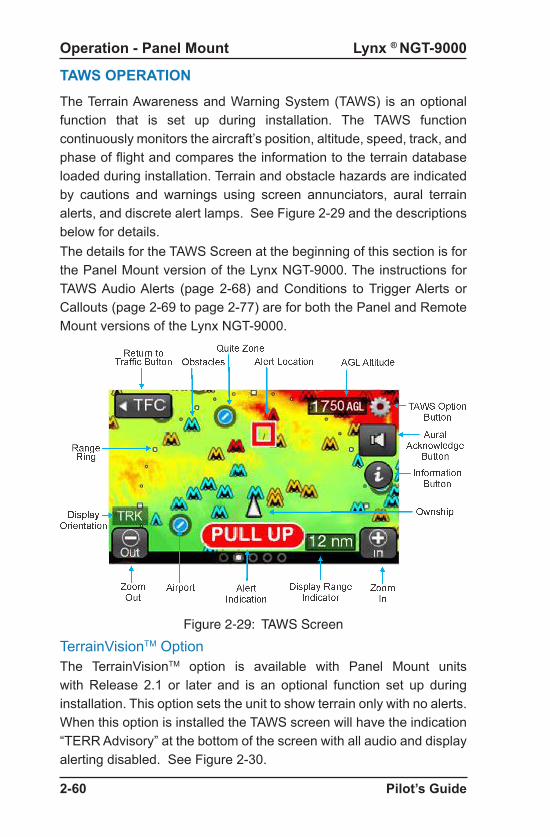
Lynx ® NGT-9000
Pilot’s Guide2-60
Operation - Panel Mount
TAWS OPERATION
The Terrain Awareness and Warning System (TAWS) is an optional function that is set up during installation. The TAWS function continuously monitors the aircraft’s position, altitude, speed, track, and phase of flight and compares the information to the terrain database loaded during installation. Terrain and obstacle hazards are indicated by cautions and warnings using screen annunciators, aural terrain alerts, and discrete alert lamps. See Figure 2-29 and the descriptions below for details.The details for the TAWS Screen at the beginning of this section is for the Panel Mount version of the Lynx NGT-9000. The instructions for TAWS Audio Alerts (page 2-68) and Conditions to Trigger Alerts or Callouts (page 2-69 to page 2-77) are for both the Panel and Remote Mount versions of the Lynx NGT-9000.
Figure 2-29: TAWS Screen
TerrainVisionTM OptionThe TerrainVisionTM option is available with Panel Mount units with Release 2.1 or later and is an optional function set up during installation. This option sets the unit to show terrain only with no alerts. When this option is installed the TAWS screen will have the indication “TERR Advisory” at the bottom of the screen with all audio and display alerting disabled. See Figure 2-30.

Lynx ® NGT-9000
Pilot’s Guide 2-61
Operation - Panel Mount
Figure 2-30: Terrain Display Only - No Alerts Screen
Limitations• The TAWS function shall not be used as a navigation instrument. It
is not intended to provide navigational guidance nor to relieve pilots from following published navigational procedures, routes, altitude restrictions, and/or instructions from air traffic control agencies except in response to alerts to avoid potentially hazardous terrain and/or obstacles. The terrain screen is intended to serve as a situational awareness tool only.
• Terrain elevation recorded in the database refers to the actual ground or water; it does not include trees, shrubs, or ice.
• TAWS does not operate in north of 70° N or south of 70° S.• TAWS will use all airport runways included in the database. Contact
Jeppesen® if a runway is not included in the database.• Some Aircraft may be equipped with an external CAWS or TAWS
type system that has higher priority audio annunciation that will delay traffic or terrain alerts.
Defining Terrain AlertsA caution alert as an alert that requires immediate pilot awareness and corrective action usually necessary involving stop descending or initiate either a climb or a turn, or both as necessary, based on analysis of all available instruments and information.
A warning alert as an alert that requires immediate pilot action to initiate and continue a climb that will provide maximum terrain clearance, or any similar approved vertical terrain escape maneuver, until all alerts cease. Vertical maneuvers are only recommended, unless either operating in visual meteorological conditions (VMC), or the pilot determines, based on all available information, that turning in addition to the vertical escape maneuver is the safest course of action, or both.

Lynx ® NGT-9000
Pilot’s Guide2-62
Operation - Panel Mount
Traffic ButtonThis button is located on the far left side of the screen and is labeled “TFC” with a left facing triangle. Tap the button to return to the Traffic Application screen.
Zoom ButtonsZoom In (+) and Zoom Out (-) buttons are located on the bottom of screen. The buttons are used to change the display range shown on the display. Display range options for the Graphic Application screen are 2 (minimum), 6, 12, and 24 (maximum) nmi.
Display Range IndicatorThis indication is a readout of the selected display range and is located in the lower right corner of the display.
Display Orientation IndicatorThe display orientation indicator is located on the lower left side of the screen and is shown as either, No indication (default installed direction source of heading or track), a white/green chevron indicating North-Up orientation, or has the letters “TRK” indicating the installed heading source has failed and the GPS track is now being used. The display orientation indicator is not shown during normal operation. Installations with heading will have a default display orientation of heading up. Installations without heading will have a default display orientation of track up.When installations without heading are on the ground with no valid track information, the screen reverts to north up depiction and indicates the north chevron.When installations with heading source have a heading failure, if track is valid, the screen will revert to track up and indicate “TRK”. If track is invalid (sitting on ground), then the screen will be north up.
Aural Acknowledge Button
This button is shown on the right side of the screen and appears as a speaker icon when a terrain caution or warning alert occurs. Tap the button to silence the aural part of the current terrain alert. The button is then removed from the screen until another alert occurs.
Note - Some aircraft may be equipped with a yoke or panel mounted acknowledge button that performs the same function.

Lynx ® NGT-9000
Pilot’s Guide 2-63
Operation - Panel Mount
Ownship Symbol The ownship symbol is a white triangle when the display orientation is direction-up (true heading or true track-up are valid) and is centered horizontally, but moved down to the lower one third of the screen. An ownship velocity vector line uses ownship track and ground speed to indicate 30 seconds of ownship travel.The ownship symbol is a black/white circle when the display orientation is north-up and is located in the center on the screen.
Obstacle SymbolsObstacles are depicted as triangular shape objects that can be either small or tall; colored as either cyan, yellow, or red; and shown as a single object or as a group. Obstacles are shown when the display range is 2, 6, and 12 nmi.
A small obstacle is shown for obstacles that are 200ft to <1,000ft tall. Tall obstacles are shown for obstacles that are > 1,000ft. Obstacles that are < 200ft are not shown on the TAWS screen.
Obstacle color is based on obstacle elevation (MSL altitude at the top of the obstacle) compared to the aircraft altitude. Cyan colored obstacles are > 1,000ft below the aircraft. Amber colored obstacles are between 1ft and 1,000ft below the aircraft, and red colored obstacles are equal to or above the aircraft altitude.
NOTEWhile obstacles are enabled, TAWS is capable of generating alerts on all obstacles included in the database. However, due to incomplete obstacle data and display de-cluttering techniques such as altitude filtering and obstacle coalescing, every obstacle may not be depicted on the Terrain Display.
AGL Altitude ReadoutThe Above Ground Level Altitude readout is located in the top right of the screen. The readout has a upper limit of 9,950ft. The readout is removed from the screen if the altitude is > 10,000ft or when sitting on the ground (0 ft AGL).

Lynx ® NGT-9000
Pilot’s Guide2-64
Operation - Panel Mount
Airport SymbolsThe symbol for the different types of airports are described in Table 2-5. Airport symbols are shown on the screen when the display range is 12 nmi or less.
Airport Symbol OperationTap the symbol to display the Airport Identifier and the Information button on the right side of the screen.
Tap the Information Button to open the TAWS Airport Text screen. It’s operation is identical to the “Weather Map Text Screen”. Refer to Figure 2-22 on page 2-53.
Tap an area of the screen without an airport symbol to deselect. The airport symbol is also deselected when the distance between the airport symbol and ownship is > 35 nmi.
Table 2-5: Airport Symbols
DESCRIPTION SYMBOL
Towered Soft Surfaced Airport
Non-towered Soft Surfaced Airports
Towered Hard Surfaced Small Airports(<8,069 ft runway)Non-towered Hard Surfaced Small Airports(<8,069 ft runway)Towered Hard Surfaced Large Airports(> 8,069 ft runway)Non-towered Hard Surfaced Large Airports(> 8,069 ft runway
Estimated Quiet Zone Around Airport Symbolson the TAWS display the 1.2 nmi radius gray-shaded area depicted around each airport symbol is the estimated quiet zone. It is used as a visual reminder that TAWS does not generate predictive alerts in the area near airport runways.

Lynx ® NGT-9000
Pilot’s Guide 2-65
Operation - Panel Mount
TAWS Terrain Color Legend
Each color represents a terrain elevation in relation the aircraft’s current altitude. Table 2-6 shows color samples at 500 ft steps. The system provides a smooth color transition to changing terrain elevations and aircraft altitudes.
Table 2-6 Terrain Color Scheme
The TAWS system has a predictive terrain alert “or quiet zone” around each airport runway to help reduce nuisance alerts during a normal takeoff or landing procedures. GPWS-type alerts such as ‘excessive descent rate’, however, are still active and will alert in this area.
Note that the predictive alert suppression is related to the location of the alert, not the position of the aircraft. Aircraft within a quiet zone may still predict alerts on terrain or obstacles outside the quiet zone. See the ‘forward looking terrain avoidance (FLTA)’ section for more information on quiet zones.

Lynx ® NGT-9000
Pilot’s Guide2-66
Operation - Panel Mount
Figure 2-31: TAWS Airport Text Screen
The top portion of the screen is a gray banner that provides the following information and operation:
• Tap the Done button remove the TAWS Airport Text screen and return the left side application screen.
• Display of the Mode A squawk code.• Reply “R” or Ident “ID” indicator shown to the right of the squawk
code when either function is active. • Display of the current transponder operating mode status indicator
with green text. An amber “Fail” is shown when the transponder function has failed.
• Product Select button opens a Product Select window. Refer to Figure 2-22. The available product are METAR, TAF, and NOTAM. If the selected product text data report is not available, the display area indicates this by displaying the selected product with a “not available” message.
TAWS Airport Text ScreenThe TAWS Airport Text screen is used to show text report data from the selected airport symbol the same as the FIS-B Textual Products Page. See Figure 2-31.
The screen is removed from view when another application is activated on the right screen or if the selected airport symbol is deselected.
Information Button (i)
The Information button is shown on the screen, located on the right side of the screen, after a airport symbol is selected. The button is gray in color and labeled with an “i” icon. Tap the button to show the TAWS Airport screen on the left side of the screen.

Lynx ® NGT-9000
Pilot’s Guide 2-67
Operation - Panel Mount
TAWS Display AlertsWhen a TAWS Caution or Warning Alert is detected, the appropriate alert symbol is depicted at the location of the alert on the terrain map. Red or Amber Alert Text indicators which relate to the active TAWS Alert are shown at the bottom center of the screen. Refer to Figure 2-31 and Table 2-7. The display alert is accompanied by an aural announcement.
The TAWS Inhibited indicator is shown when Alerting is inhibited using the TAWS options Screen. Note - Off display alerting may occur if display is at low range. Expanding of the range will then reveal the alert area.
Figure 2-32: TAWS Options Screen
TAWS Options ButtonThe gear shaped Options Button is located in the upper right corner of the right application screen. Tap the button to open the options screen. Refer to Figure 2-32.
TAWS Options ScreenThe Settings latch button opens a screen providing the setting of Obstacles and Alerting status. Both buttons may be set to “Enabled” or “Inhibited”. Both buttons are set to “Enabled at start-up.
• Selecting “Inhibited” on the Obstacles button removes obstacles from the TAWS display and TAWS will not include obstacles as part of the alert detection. This is used to stop TAWS alerting when landing at an unknown airport or runway.
• Selecting “Inhibited” on the Alerting button places an “Inhibited” indicator on the screen and removes visual TAWS alerts and stops aural alerts from occurring.
Tap the Done button to close the Options Screen.

Lynx ® NGT-9000
Pilot’s Guide2-68
Operation - Panel Mount
Table 2-7: TAWS Display Alerts
TAWS Warning Symbol
TAWS Caution Symbol
TAWS Warning Text
TAWS Caution Text
TAWS Caution Obstacle Text
TAWS Inhibited
TAWS Audio Alerts
Aural announcements for caution alerts are repeated every 7 seconds and require immediate flight crew awareness and possible action. The exact phrase used in the aural announcement depends on the instal-lation setup, the type of alert condition, and whether the alert is due to terrain or an obstacle. See Table 2-8.
Aural announcements for warning alerts are repeated continuously and require immediate flight crew action. The exact phrase used in the aural announcement depends on the installation setup, the type of alert condition, and whether the alert is due to terrain or an obstacle. See Table 2-8.
500 ft Altitude CalloutThe 500 ft altitude callout consists of the aural announcement, “five hundred.” The callout is intended to provide situational awareness to the flight crew and does not necessarily indicate a hazardous condition.

Lynx ® NGT-9000
Pilot’s Guide 2-69
Controls and Indicators
Table 2-8: Caution & Warning Alert Phrases*
ALERT CONDITION
CAUTION ALERT
PHRASES
Warning Alert
PhrasesReduced
Required Terrain Clearance (RTC) (Figure 2-35)
orImminent Terrain Impact (ITI)
Figure 2-36)
“Caution, Terrain; Caution, Terrain!”
Or “Caution, Obstacle; Caution, Obstacle!”
“Terrain, Terrain; Pull Up, Pull Up!”
Or “Obstacle, Obstacle; Pull Up, Pull Up!”
“Terrain Ahead; Terrain Ahead!”
Or “Obstacle Ahead; Obstacle Ahead!”
“Terrain Ahead, Pull Up;
Terrain Ahead, Pull Up!”
Or “Obstacle, Obstacle; Pull Up, Pull Up!”
Premature Descent
(Figure 2-37)“Too Low, Terrain!” None
Excessive Descent Rate (Figure 2-38)
“Sink Rate!” None
Negative Climb Rate or
Altitude Loss After Takeoff (Figure 2-39)
“Don’t sink!”
None“Too low, terrain!”
* The primary or secondary phrase options are setup at installation.
Conditions to Trigger Alerts or CalloutsThe TAWS function uses Forward Looking Terrain Avoidance (FLTA) and Ground Proximity Warning System (GPWS) functionality to determine when a terrain alert or altitude callout is triggered due based on the following conditions:
• Reduced required terrain clearance (FLTA)• Imminent terrain impact (FLTA)• Premature descent• Excessive descent rate (GPWS)• Negative climb rate or altitude loss after takeoff (GPWS)• Altitude of 500 ft (GPWS)
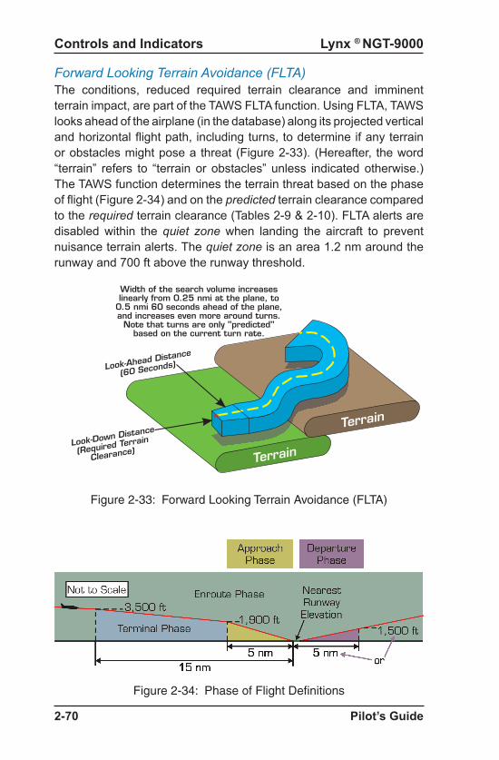
Lynx ® NGT-9000
Pilot’s Guide2-70
Controls and Indicators
Figure 2-33: Forward Looking Terrain Avoidance (FLTA)
Figure 2-34: Phase of Flight Definitions
Look-Ahead Distance
(60 Seconds)
Look-Down Distance
(Required Terrain
Clearance)Terrain
Terrain
Width of the search volume increaseslinearly from 0.25 nmi at the plane, to
0.5 nmi 60 seconds ahead of the plane,and increases even more around turns.
Note that turns are only "predicted"based on the current turn rate.
Forward Looking Terrain Avoidance (FLTA)The conditions, reduced required terrain clearance and imminent terrain impact, are part of the TAWS FLTA function. Using FLTA, TAWS looks ahead of the airplane (in the database) along its projected vertical and horizontal flight path, including turns, to determine if any terrain or obstacles might pose a threat (Figure 2-33). (Hereafter, the word “terrain” refers to “terrain or obstacles” unless indicated otherwise.) The TAWS function determines the terrain threat based on the phase of flight (Figure 2-34) and on the predicted terrain clearance compared to the required terrain clearance (Tables 2-9 & 2-10). FLTA alerts are disabled within the quiet zone when landing the aircraft to prevent nuisance terrain alerts. The quiet zone is an area 1.2 nm around the runway and 700 ft above the runway threshold.

Lynx ® NGT-9000
Pilot’s Guide 2-71
Operation - Panel Mount
Figure 2-35: Reduced RTC Alert Condition
Table 2-9: Required Terrain Clearances for the Reduced RTC Alert Condition
Reduced Required Terrain Clearance (RTC)The reduced RTC alert condition (Figure 2-35) occurs when the aircraft is currently above the altitude of the upcoming terrain along the projected flight path, but the projected terrain clearance is less than the required terrain clearance (Table 2-9).
The TAWS function issues a caution alert 60 seconds before the offending terrain and a warning alert 30 seconds before the offending terrain.
CautionAlert
“Caution, terrain; caution, terrain!”*
“Terrain, terrain; pull up, pull up!”*
60 sec30 sec
WarningAlertRequired Terrain
Clearance
Projected Terrain Clearance
TERRAIN PULL UP

Lynx ® NGT-9000
Pilot’s Guide2-72
Operation - Panel Mount
Figure 2-36: ITI Alert Condition
Table 2-10: Required Terrain Clearances for the ITI Alert Condition
Terminal 350 ft
Approach 150 ft
Enroute 700 ft
Required Terrain ClearancePhase of Flight
Departure 100 ft
Imminent Terrain Impact (ITI)The ITI alert condition (Figure 2-36) occurs when your aircraft is currently below the altitude of the upcoming terrain along the projected flight path, and the projected terrain clearance is less than the required terrain clearance (Table 2-10).
The TAWS function issues a caution alert 60 seconds before the offending terrain and a warning alert 30 seconds before the offending terrain.
CautionAlert
60sec30 sec
WarningAlert
Required Terrain
Clearance
Projected Terrain
Clearance
“Caution, terrain; caution, terrain!”*
“Terrain, terrain; pull up, pull up!”*
TERRAIN PULL UP

Lynx ® NGT-9000
Pilot’s Guide 2-73
Operation - Panel Mount
Premature DescentThe premature descent alert condition (Figure 2-37) occurs when your aircraft is significantly below the normal final approach flight path to the nearest runway (typically a 3-degree implied glideslope). This condition may exist for a variety of reasons such as poor visibility or nighttime operation. If this condition is not corrected, then likely the aircraft will touch down short of the runway even if the aircraft is properly configured for landing and is descending at a normal rate. The premature descent alert is only enabled in the terminal and approach phases.
The TAWS function uses the aircraft’s current position, flight path information, and the runway database to detect the premature descent condition and then a caution alert is sent.
TAWS function calculates premature descent alerts based on the aircrafts proximity to the closest runway and measures the aircrafts distance from that runway once per second. The closest runway may or may not be the runway intended for a landing.
WARNING
Figure 2-37: Premature Descent Alert Condition
12 nm
Caution Alert:“Too low, terrain!”
700 ft
15 nm 12 nm 5 nm 2 nm 1 nm
350 ft
150 ft
NearestRunway
Premature Descent
Normal Final Approach
TERRAIN

Lynx ® NGT-9000
Pilot’s Guide2-74
Operation - Panel Mount
Ground Proximity Warning System (GPWS) AlertingThe alert and callout conditions for excessive descent rate, negative climb rate or altitude loss after takeoff, and altitude of 500 ft are determined by the TAWS function subtracting the terrain elevation stored in its terrain database from the GPS-based aircraft altitude to calculate height above terrain.
Excessive Descent RateThe excessive descent rate alert condition (Figure 2-38), also known as GPWS Mode 1, occurs when the aircraft is descending too fast for the aircrafts current height above terrain, regardless of the aircrafts flap position. More precisely, it’s when your aircraft’s descent rate and height above terrain fall within the envelopes shown in Figure 2-39.
Figure 2-38: Excessive Descent Rate Alert Condition
Figure 2-39: Excessive Descent Rate Graph
Caution Alert:“Sink Rate!”
Warning Alert:“Pull up!”
The aircrafts descent rate determines theheight at which alerts begin to occur.
TERRAIN
PULL UP
5,000
4,000
3,000
2,000
1,000
2,000 4,000 6,000 8,000 10,00000
Hei
ght A
bove
Ter
rain
(ft)
Descent Rate (fpm)
Caution
Alert:
“SinkRate
!”
Warning Alert:“Pull up!”
PULL UP
TERRAIN

Lynx ® NGT-9000
Pilot’s Guide 2-75
Operation - Panel Mount
Negative Climb Rate or Altitude Loss After TakeoffThese alert conditions (Figure 2-40), also known as GPWS Modes 3A and 3B are enabled between 50 and 700 ft above the runway after takeoff or after a missed approach. The negative climb rate alert condition is based on descent rate. The altitude loss after takeoff alert condition is based on accumulated altitude loss in order to catch descents that are too gradual to qualify for the negative climb rate alert condition. The two together ensure that practically any descent after takeoff or missed approach will trigger an alert.
Figure 2-40: Negative Climb Rate or Altitude Loss After Takeoff Alert Condition
“Don’t sink!”or
“Too low, terrain!” Caution Alert
700 ft
50 ftRunway
TERRAIN

Lynx ® NGT-9000
Pilot’s Guide2-76
Operation - Panel Mount
When the aircraft’s height above the runway elevation and its descent rate or altitude loss fall within the envelopes shown in figures 2-40 and 2-41, TAWS issues a caution alert.
Figure 2-41 Negative Climb Rate Graph
Figure 2-42: Altitude Loss After Takeoff Graph
600
500
700
400
300
200
100
1,000 2,000 3,000 4,000 5,000 7,0006,00000
Hei
ght A
bove
Run
way
(ft)
Descent Rate (fpm)
Caution Alert:“Don’t sink!”
or“Too low, terrain!”
TERRAIN
600
500
700
400
300
200
100
20 40 60 80 100 12000
Hei
ght A
bove
Run
way
(ft)
Altitude Loss (ft)
Caution Alert:“Don’t sink!”
or“Too low, terrain!”
TERRAIN

Lynx ® NGT-9000
Pilot’s Guide 2-77
Operation - Panel Mount
Altitude of 500 ftThis condition (Figure 2-43), also known as a subset of GPWS Mode 6, occurs when the aircraft descends within 500 ft of the terrain during enroute mode, or when the aircraft is in enroute mode in level flight but the terrain below rises up within 500 ft of the aircraft. It also occurs when the aircraft descends within 500 ft of the nearest runway threshold elevation during terminal or approach mode. When any of these conditions occurs, TAWS issues an aural 500 ft altitude callout (“five hundred”). The 500 ft altitude callout does not occur when the aircraft is ascending or during departure or missed approach mode. The callout is ready to play again only after the aircraft ascends to 700 ft above the terrain or runway.
Figure 2-43: Altitude of 500 Feet Callout Condition
“Five Hundred”
“Five Hundred”
500 ft
500 ft

Lynx ® NGT-9000
Pilot’s Guide2-78
Operation - Panel Mount
LIGHTNING OPERATION
Lightning detection is an optional function that is set up during installation. The Lightning function continuously monitors electrical discharges from thunderstorms within a 200 nmi radius of the aircraft and plots the location of the discharges as cells or strikes on the right application screen. See Figures 2-43 and 2-44 and the descriptions below for details.
Refer to the Stormscope (WX-500) Users Guide 009-11501-001 for in-depth details.
Figure 2-44: Lightning Screen 360 View
Never use the Lightning system to attempt to penetrate a thunderstorm. The FAA Advisory Circular, Subject: Thunderstorms, and the Airman’s Information Manual (AIM) recommend that aircraft are to “avoid by at least 20 miles any thunderstorm identified as severe or giving an intense radar echo.”
WARNING
Traffic ButtonThis button is located on the far left side of the screen and is labeled “TFC” with a left facing triangle. Tap the button to return to the Traffic Application screen.

Lynx ® NGT-9000
Pilot’s Guide 2-79
Operation - Panel Mount
Figure 2-45: Lightning Screen 120 View
Ownship Symbol The ownship symbol is a white triangle with the nose of the ownship symbol corresponding to the ownship position. • When the View mode is 360 the symbol is centered on the screen.
See Figure 2-44.• When the View mode is 120 the symbol is centered at the bottom
of the screen. See Figure 2-45.
Zoom ButtonsZoom In (+) and Zoom Out (-) buttons are located on the bottom of screen. The buttons are used to change the display range shown on the screen. Display range options for the Lightning screen is 25, 50, 100, and 200 nmi.
360 ViewDisplay range 25 NM has a white outer circle with Azimuth indicators at 30 degree intervals. See Figure 2-44.
Display range 50, 100, and 200 has Azimuth indicators at 30 degree intervals in an outer ring. An inner white circle surrounds the Ownship that represents 25 nmi from the Ownship.
120 ViewDisplay range 25 NM has a white outer arc with Azimuth indicators at + / - 30 degree with white radial lines extending from the nose of the ownship symbol. See Figure 2-45.
Display range 50, 100, and 200 has Azimuth indicators at +/- 30 and +/- 60 degrees with white radial lines extending from the nose of the ownship symbol. An inner white arc extends from the +/- 60 radial lines that represents 25 nmi from the Ownship.

Lynx ® NGT-9000
Pilot’s Guide2-80
Operation - Panel Mount
Mode ButtonThis toggle button is located on the left side of the screen and is labeled “MOD”. The button has two selections “STK (strike) and “CEL” (cell). The lower half of the button shows the current mode selection in green text. Refer to Table 2-11 for Lightning Symbology.• Set the mode for Strike to display strike data on the screen. Strike
data is most useful during periods of light electrical activity as this will show the strengthening thunderstorm sooner then cell data.
• Set the mode for Cell to display cell data on the screen. Cell data is used during heavy electrical activity.
Note - Other atmospheric phenomena can cause isolated discharge points in the Strike Mode screen. Clusters of two or more discharge points do indicate thunderstorm activity when they reappear after clearing the screen. In the Cell Mode screen even a single discharge point may represent thunderstorm activity and should be avoided.
Table 2-11: Lightning Symbols
STRIKE CELL STRIKE AGE
0-10 sec
10 sec - 1 min
1-2 min
2-3 min
Clear ButtonThis button is located on the far right side of the screen and is labeled “CLR”. Tap the button to clear the screen of the current lightning data (strike or cell).
Clearing the lightning data periodically helps in determining if a storm is strengthening or dissipating. A strengthening storm is indicated by the lightning data reappearing faster and in larger numbers, while a dissipating storm appears slower and with fewer number of strikes.

Lynx ® NGT-9000
Pilot’s Guide 2-81
Operation - Panel Mount
Lightning Options ButtonThe gear shaped Options Button is located in the upper right corner of the right application screen. Tap the button to open the Lighting Setting page. Refer to Figure 2-46.
Lightning Settings (View Mode, Stabilization, Status)The Settings page is active when “Settings” label is green. The page shows the WX-500 software information, WX-500 Status information, current display View and Stab (stabilization) status.
• The View Mode toggle button can be set for either 120 or 360 degrees.
• The Stab Mode toggle button can be set for either On or Off. When set to “On” the position of the electrical discharge points on the display are automatically adjusted as the aircraft changes heading. Stab should always be “On” except for system without a heading source or if heading is invalid. It is recommended that Stabilization be set to “Off” if heading is invalid and remain off until heading input is corrected. When set to Off the heading indicator is not displayed and a “STAB OFF” message is shown on the screen.
• Along with the software information the status of the WX-500 is indicated as “OK”in white text, “Degraded” in amber text, or “Failed” in red text. If degraded or failed is shown a fault code and description is shown. Multiple codes will rotate one at a time for 3 second periods. A list of error messages and fault information is provided in the WX-500 User’s Guide (009-11501-001).
Press the Done button to return to the lightning application screen. Note - The Tests page is used for installation of the WX-500 and should be ignored.
Figure 2-46: Lightning Setting Page

Lynx ® NGT-9000
Pilot’s Guide2-82
Operation - Panel Mount
Heading StabilizationThe heading stabilization automatically adjusts the position of the discharge points on the screen when the aircraft changes heading.
• This feature is not available for aircraft with out a heading input or if heading data is invalid.
• If heading data is invalid as indicated by amber dashes shown for the heading indicator, then stabilization should be set for Off using the Lighting Options page.
• If heading stabilization is Off tap the “CLR” button to clear the discharge points after each heading change to display new discharge points in the proper location relative to the nose of the aircraft.
Application Indicator / Nearby StrikeThe Application Indicator is located on the bottom of the screen. It shows the current application screen (lightning) compared to the other enabled application screens.
A Nearby Strike Indication (activity indicator) is shown over the lightning application dot . It fades in/out when active to draw attention to possible storm activity. See Figure 2-45.
Heading IndicatorThe heading indicator is located on the top right side of the screen and provides a three digit (001 to 360) display of heading.
If heading is invalid the digits are replaced with three amber dashes and heading stabilization is off.
Note - Heading is optional and this indicator will not be shown if heading is not used.
Strike Rate IndicatorThe Strike Rate Indicator is located in the upper right corner of the screen and is labeled “RATE”. The indicator shows the approximate number of strikes per minute providing the user a way to determine if thunderstorms are strengthening or weakening.
Strike Rate Trend ArrowThis white arrow is shown to the left of the Rate Indicator. When the arrow is shown pointing up it indicates an increase in strikes while a down pointing arrow indicates a decrease in strikes.

Lynx ® NGT-9000
Pilot’s Guide 2-83
Operation - Panel Mount
MAINTENANCE MODE
Maintenance mode is used to perform a screen calibration. See Figure 2-47.
1. Apply power to the Lynx NGT-9000.2. When the splash screen is shown press and hold (continue
holding when the status and version screens are showing) in the lower left corner of the display until the Activate Maintenance Mode window is shown on the right screen.
3. Tap the Yes button to restart the unit in Maintenance Mode. Note - Pressing the No screen button or 10 seconds of inactivity starts normal operation mode.
4. Tap the Screen Calibration text.5. In the Calibration screen touch and release each target shown.
(Four calibration targets and two verification targets). Each must be completed within 15 seconds or the Calibration Time out message is shown. The unit returns to the main screen.
6. If normal operation is desired cycle power to the unit or tap the Reboot text on the main screen followed by tapping the Main App > text to perform a warm startup.
7. When in normal operation check that the touch screen accuracy has improved. If the accuracy has not improved, try the calibration procedure again. If the issue continues contact ACSS Field Service for help in resolving the issue prior to removing the unit for repair.

Lynx ® NGT-9000
Pilot’s Guide2-84
Operation - Panel Mount
ActivateMaintenance Mode?
No Yes
MaintenanceScreen Calibration >
Reboot >
RebootMain App >< Back
Maint No-WiFi >Maint With-WiFi >
Ground Test >
Figure 2-47: Maintenance Screens
Touch and Release Target

Lynx ® NGT-9000
Pilot’s Guide 3-1
CHAPTER 3OPERATION - REMOTE MOUNT
INTRODUCTION
Operational control of the Remote Mount Lynx NGT-9000R is accomplished with a CP-2500 Control Panel or a compatible control panel. This chapter describes the operation of the CP-2500 interfaced to the Lynx NGT-9000R. Other control panel interfaces are described by the respective pilot’s guide. Details on the optional cockpit switches and indicator lamps are provided in chapter 4.
POWER ON1. There is no power on/off switch for the Remote Mount Lynx NGT-
9000R. Depending on the aircraft, use either the battery switch or avionics master switch to apply power. Normal operation begins within 20 seconds of applying power. During start up the unit checks for valid configuration data and initializes self tests.
2. If not already accomplished, press the small knob button to apply power to the CP-2500 Control Panel.
3. The Lynx NGT-9000 GPS begins acquiring position.
a. After power is applied to the CP-2500 and the self test passes, the CP-2500 briefly displays “OK” (or a status message is seen). Followed by the scrolling of the firmware and hardware levels of the CP-2500 (approximately 15 seconds). The CP-2500 then reverts to normal operation. The message “GPS-INIT” will be shown for approximately until a GPS position is acquired.
• If an ADS-B System Fail is displayed after approximately 2 minutes, then the GPS position was not acquired. Verify that the aircraft (and GPS antenna) have a clear view of the sky. If the problem continues.
b. If installed the ADS-B Out Fail lamp is Off for 2 minutes and then flashes (1 second On/Off) indefinitely until a GPS position is acquired. Normally, GPS acquisition occurs within the first minute and therefore no lamp flashing occurs.
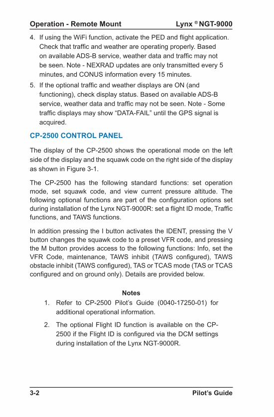
Lynx ® NGT-9000
Pilot’s Guide3-2
Operation - Remote Mount
CP-2500 CONTROL PANEL
The display of the CP-2500 shows the operational mode on the left side of the display and the squawk code on the right side of the display as shown in Figure 3-1.
The CP-2500 has the following standard functions: set operation mode, set squawk code, and view current pressure altitude. The following optional functions are part of the configuration options set during installation of the Lynx NGT-9000R: set a flight ID mode, Traffic functions, and TAWS functions.
In addition pressing the I button activates the IDENT, pressing the V button changes the squawk code to a preset VFR code, and pressing the M button provides access to the following functions: Info, set the VFR Code, maintenance, TAWS inhibit (TAWS configured), TAWS obstacle inhibit (TAWS configured), TAS or TCAS mode (TAS or TCAS configured and on ground only). Details are provided below.
Notes1. Refer to CP-2500 Pilot’s Guide (0040-17250-01) for
additional operational information.
2. The optional Flight ID function is available on the CP-2500 if the Flight ID is configured via the DCM settings during installation of the Lynx NGT-9000R.
4. If using the WiFi function, activate the PED and flight application. Check that traffic and weather are operating properly. Based on available ADS-B service, weather data and traffic may not be seen. Note - NEXRAD updates are only transmitted every 5 minutes, and CONUS information every 15 minutes.
5. If the optional traffic and weather displays are ON (and functioning), check display status. Based on available ADS-B service, weather data and traffic may not be seen. Note - Some traffic displays may show “DATA-FAIL” until the GPS signal is acquired.

Lynx ® NGT-9000
Pilot’s Guide 3-3
Operation - Remote Mount
Figure 3-1: Example of CP-2500
Large Knob
Small Knob
Display
PushButtons
Small KnobButton
SquawkCode
OperationalMode
I V M
ALT 1 2 0 0
Power Off
To remove power to the CP-2500, press and hold the small knob button until the message “Power Down” is shown on the display. (Note - This does not remove power to the Lynx NGT-9000R.)
Enter the Squawk Code1. Rotate the large knob to select the squawk page.2. Press the small knob. Observe that the left most digit blinks. 3. Rotate the small knob to change the number, rotate the large
knob to select the next digit. Repeat until all digits are changed. 4. Press the small knob or allow the screen to time out to commit
the change.
NOTEThe four digit squawk code may be missing from the “Alt” and “On” screen of the CP-2500 (code appears OK in “Sby” mode) if the NGT-9000R has a system message, a system failure, or if the GPS signal is missing for greater than 2 minutes.
Set Operational ModeRotate the small knob to set the operation mode to Altitude (Alt), On, or Standby (Sby). The Altitude mode is always selected unless Air Traffic Control (ATC) requests a change or if there is a known problem with the control panel or NGT-9000.

Lynx ® NGT-9000
Pilot’s Guide3-4
Operation - Remote Mount
View Pressure Altitude1. Rotate the large knob until the “Altitude” is shown. 2. Rotate the large knob to return to normal operation or screen will
time out within 10 seconds.
NOTEINVLD PA is shown if no pressure altitude source is available from the aircraft. In some installations, it may take 2-3 minutes after power on to receive valid pressure altitude from the encoder.
Set Flight IDThe flight ID function is optional and is part of the configuration options set during installation of the NGT-9000.
1. Rotate the large knob to select ID. 2. Press the small knob to select the first digit. 3. Rotate the small knob to change the digit (CCW) or character
(CW). 4. Rotate the large knob to move the cursor to the next digit. 5. Press the small knob to commit. Deactivate the Flight ID
1. Rotate the large knob CW to move the cursor off the right side of the display.
2. Continue rotating unit only dashes fill the display. 3. Press the small knob to commit.
IDENT Activation
The use of this button is directed by Air Traffic Control (ATC). 1. Press the I (IDT) button. See Figure 2-72. The IDENT message is sent by the ADS-B unit for 18 sec. 3. Observe that IDENT is momentarily (or for 18 sec. for Release
2.1 or later) displayed.
VFR Code SelectPress the V (VFR) button to set the squawk code to a programmed VFR code that preset in the menu (see VFR code below).
• Typically the VFR code is set to 1200 (in the United States). • Press the button again returns the code to the previous squawk
code.

Lynx ® NGT-9000
Pilot’s Guide 3-5
Operation - Remote Mount
View Info
Available on ground only.
1. Press the M (Menu) button.2. Rotate the large knob to scroll the menu to Info 3. Press the small knob button to select. 4. The Info menu option shows the following information about the
unit:• Status (OK or FAIL)• Hardware (HW Rev) configuration• Firmware (FW Rev) configuration
5. Rotate the large knob to scroll through the information. 6. Scroll to “Done” and press the small knob to exit. 7. Press the M button to exit back to normal operation.
Set VFR Code
The VFR code can be changed from the default (always set to 1200 in the United States).
1. Press the M (Menu) button.2. Rotate the large knob to scroll the menu to VFR 3. Press the small knob to select the first digit. 4. Rotate the small knob to set the number. 5. Rotate the large knob to move the cursor to the next digit (4 total). 6. Press the small knob when done.
Traffic Advisory Aural Acknowledge and Reply
This function is a configuration option.
1. When a Traffic advisory is heard press the small knob button to acknowledge the audio alert and silence the current audio message.
2. Press the small knob button again to replay the traffic advisory if still available.
NOTESThe “TRAFFIC” message must be displayed when the button is pressed to acknowledge or replay the aural.
Some aircraft may be equipped with a yoke or panel mounted acknowledge button that will silence the current audio message only.

Lynx ® NGT-9000
Pilot’s Guide3-6
Operation - Remote Mount
Enable On Ground TAS/TCAS Operation
This function is a configuration option. In the air TAS/TCAS is always active. The TAS/TCAS On Ground Setting is available only when the aircraft status is “On Ground”. After takeoff it is canceled and must be reactivated.1. Press the M (Menu) button. 2. Rotate the large knob to scroll the menu to “TRAF”.3. Press the small knob button to select.4. Rotate the small knob to set the TAS/TCAS mode to “Standby” or
“Operating”. 5. Press the small knob when done.
• The message “TAS OPR” or “TCAS OPR” shown when TAS/TCAS is operating while on ground.
TAWS Alert Aural AcknowledgeThis function is a configuration option.When a TAWS alert is heard and the messages “PULL UP” or “TERRAIN” are shown on the CP-2500 display or indicator lamps (if installed). Press the small knob button to acknowledge the audio alert and silence the current audio message. Note - Some aircraft may be equipped with a yoke or panel mounted acknowledge button that performs the same function.
Inhibit TAWS Alert MessageThis function is a configuration option. The TAWS option default setting is “Enable”.
1. Press the M (Menu) button. 2. Rotate the large knob to scroll the menu to TAWS3. Press the small knob button to select.4. Rotate the small knob to set the TAWS mode to Enabled or
Inhibited5. Press the small knob when done.
• Inhibiting TAWS stops TAWS visual alerts from being displayed on the CP-2500 and stops TAWS aural alerts from occurring.
• The message “TAWS INH” is shown on the display while the TAWS option is inhibited.
Valid alert conditions that put the aircraft in danger may be missed if all terrain alerts are in inhibited.
WARNING

Lynx ® NGT-9000
Pilot’s Guide 3-7
Operation - Remote Mount
Inhibit TAWS ObstaclesThe TAWS Obstacle option default setting is “Enabled”.
1. Press the M (Menu) button. 2. Rotate the large knob to scroll the menu to Obstacle3. Press the small knob button to select.4. Rotate the small knob to set the TAWS Obstacle mode to Enabled
or Inhibited5. Press the small knob when done.
• Inhibiting TAWS Obstacles results in TAWS not including obstacles as part of the alert detection.
• The message “OBST INH” is shown on the display while the obstacle option is inhibited.
NGT-9000R (Release 1.2)1. Press the M (Menu) button.
2. Rotate the large knob to scroll the menu to Maintenance.
3. Press small knob to view status “Self Test” “Disable”.
4. Turn the small knob to change status to “Enable”.
5. Press the small knob again to activate self test.
6. When activated, the screen momentarily displays “Test Started”
7. The results of the test are that during the test three targets are shown on the optional Traffic or PED display and the ADS-B Out Fail lamp (if installed) flashes during the test. • The results shown on the display can be test passed “Tst
Pass” or test failed “Tst Fail”.8. Press the M button to exit or scroll the large knob to “Done” and
then press small knob to exit and return to normal operation.
Activate Maintenance Self TestThe maintenance item is available only when the aircraft is on ground. The procedures and the results are slightly different depending on model, version, and releases. Each of the procedures are described below.
The Self Test for the NGT-9000R has evolved with the Releases. The self test have been separated into the following paragraphs.

Lynx ® NGT-9000
Pilot’s Guide3-8
Operation - Remote Mount
NGT-9000R (Release 2.0 & 2.1)1. Press the M (Menu) button.
2. Rotate the large knob to scroll the menu to Maintenance.
3. Press small knob to enter “Self Tst”.
4. Press the small knob again to activate self test.
5. When activated, the screen momentarily displays “Test Started” followed by “Test In Progress”.• If the optional traffic or PED display is installed, each will show
three targets during the test.• If the optional ADS-B Out Fail is installed it will be ON for 10
seconds during the test.6. The results shown on the display (and over audio) can be test
passed “Tst Pass”, test failed “Tst Fail”, or test degraded “Test Degraded”.• If a failure is detected a fail message is flashed on the CP-2500
screen for 5 seconds. The possible fail messages are:• NO LRU RESPONSE• XPDR FAIL• ADS-B OUT FAIL• ADS-B IN FAIL• FIS-B FAIL• GPS FAIL• TAS FAIL• TAWS FAIL
• If a degraded condition is detected a degraded message is flashed on the CP-2500 screen for 5 seconds. The possible degraded messages are:• ADS-B OUT DEGRADED• TAS DEGRADED• GPS INIT• CONFIG MODULE - SERVICE SOON

Lynx ® NGT-9000
Pilot’s Guide 3-9
Operation - Remote Mount
NGT-9000R (Release 3.0, 3.1, 3.2)1. Press the M (Menu) button.
2. Rotate the large knob to scroll the menu to Maintenance.
3. Press small knob to enter “Self Tst”.
4. Press the small knob again to activate self test.
5. When activated, the screen momentarily displays “Test Started” followed by “Test In Progress”.• If the optional traffic or PED display is installed, each will show
three targets during the test.• If the optional ADS-B Out Fail is installed it will be ON for 10
seconds during the test.6. The results shown on the display (and over audio) can be test
passed “Tst Pass”, test failed “Tst Fail”, or test degraded “Test Degraded”.• If a failure is detected a fail message is flashed on the CP-2500
screen for 5 seconds. The possible fail messages are:• NO LRU RESPONSE• XPDR FAIL• ADS-B OUT FAIL• ADS-B IN FAIL• FIS-B FAIL• GPS FAIL• TAS FAIL• TCAS Fail• TAWS FAIL
• If a degraded condition is detected a degraded message is flashed on the CP-2500 screen for 5 seconds. The possible degraded messages are:• ADS-B OUT DEGRADED• TAS DEGRADED• TCAS DEGRADED• GPS INIT• CONFIG MODULE - SERVICE SOON

Lynx ® NGT-9000
Pilot’s Guide3-10
Operation - Remote Mount
NGT-9000R Release 1.2• NO LRU RESPONSE: The CP-2500 has detected loss of
communication with the NGT-9000R. This is a CP-2500 message that was incorporated in Firmware 15 and later.
• TAS FAIL: The TAS function has failed.
• XPNDR FAIL: The transponder function of the NGT-9000R has failed.
• ADS-B OUT FAIL: The ADS-B out is not being transmitted by the NGT-9000R due to the GPS position not being available for more than 2 minutes or possibly a failure of the NGT-9000R.
• GPS FAIL: The GPS derived position input is not functioning.
• IDENT: The IDENT message is being sent by the NGT-9000R to Air Traffic Control (ATC).(CP-2500 message.)
• GPS INIT: GPS Initialization –The GPS contained within the NGT-9000R is not ready. This message is removed after the GPS completes initialization.
• NO ADS-B COVERAGE: This message is removed once the NGT-900R begins receiving an ADS-B ground station signal.
• GND MODE: Unit is in ground test mode.
Display Messages
Messages are either received from the NGT-9000R or being annunciated from the CP-2500. Messages have priority over normal display operation and are seen scrolling across the display. Entering the menu mode will stop the messaging until the menu mode is exited.
Rotating the large knob scrolls through the prioritized messages and the normal display operation (showing operational mode and squawk code). The display begins showing the highest priority message again after 10 seconds of no activity. The priority of the messages is discussed in the CP-2500 product manuals.
The messages have evolved with the model and software releases. The following messages are listed from highest to lowest priority.

Lynx ® NGT-9000
Pilot’s Guide 3-11
Controls and Indicators
NGT-9000R Release 2.0 & 2.1• NO LRU RESPONSE: The CP-2500 has detected loss of
communication with the NGT-9000R. This is a CP-2500 message that was incorporated in Firmware 15 and later.
• GPS FAIL (Priority On Ground): The GPS derived position input is not functioning.
• GPS INIT (Priority On Ground): GPS Initialization –The GPS contained within the NGT-9000R is not ready. This message is removed after the GPS completes initialization.
• PULL UP: This is a TAWS Warning Alert that is accompanied by an aural announcement.
• TERRAIN: This is a TAWS Caution Alert that is accompanied by an aural announcement.
• TRAFFIC: This is an TAS or ATAS Traffic Advisory that is accompanied by an aural announcement.
• GND MODE: Unit is in ground test mode.• STANDBY: The STANDBY message is seen only when the
transponder is in Standby Mode. (Release 2.1 or later, CP-2500 Firmware 15 or later.)
• IDENT: The IDENT message is being sent by the NGT-9000R to Air Traffic Control (ATC).(Release 2.1 or later, CP-2500 Firmware 15 or later) (CP-2500 message.)
• TAWS FAIL: The TAWS function has failed.• TAWS UNAVAILABLE: The TAWS function is unavailable due to
not having a GPS position solution of sufficient quality.• TAS FAIL: The TAS function has failed.• ADS-B IN FAIL: The ADS-B In and ATAS functions have failed.• ADS-B IN UNAVAIL - POS: The ADS-B In and ATAS functions are
unavailable due to not having a GPS position solution of sufficient quality.
• XPDR FAIL: The transponder function has failed.
Display Messages (continued)

Lynx ® NGT-9000
Pilot’s Guide3-12
Controls and Indicators
NGT-9000R Release 2.0 & 2.1 continued• ADS-B OUT FAIL: The ADS-B out is not being transmitted by the
NGT-9000R due to the GPS position not being available for more then 2 minutes or possibly a failure of the NGT-9000R.
• TAWS INH: The TAWS function is currently inhibited.• OBST INH: The TAWS function is not alerting on obstacles.• TAS DEGRADED: The TAS function is operating in a degraded
condition.• ADS-B OUT DEGRADED: The ADS-B out function is operating in
a degraded condition.• GPS FAIL (Priority In Air): The GPS derived position input is not
functioning.
• GPS INIT (Priority In Air): GPS Initialization –The GPS contained within the NGT-9000R is not ready. This message is removed after the GPS completes initialization.
• NO ADS-B COVERAGE: This message is removed once the NGT-900R begins receiving an ADS-B ground station signal.
• FIS-B FAIL: The FIS-B function has failed.• TAS OPR: TAS is operating while the aircraft is on ground.• CONFIG MODULE - SERVICE SOON: Indicates a problem being
detected with the configuration module.
Display Messages (continued)

Lynx ® NGT-9000
Pilot’s Guide 3-13
Controls and Indicators
NGT-9000R Release 3.0, 3.1, 3.2• NO LRU RESPONSE: The CP-2500 has detected loss of
communication with the NGT-9000R. This is a CP-2500 message that was incorporated in Firmware 15 and later.
• GPS FAIL (Priority On Ground): The GPS derived position input is not functioning.
• GPS INIT (Priority On Ground): GPS Initialization –The GPS contained within the NGT-9000R is not ready. This message is removed after the GPS completes initialization.
• PULL UP: This is a TAWS Warning Alert that is accompanied by an aural announcement.
• TERRAIN: This is a TAWS Caution Alert that is accompanied by an aural announcement.
• TRAFFIC: This is an TAS/TCAS or ATAS Traffic Advisory that is accompanied by an aural announcement.
• GND MODE: Unit is in ground test mode.• STANDBY: The STANDBY message is seen only when the
transponder is in Standby Mode. (CP-2500 Firmware 15 or later.)
• IDENT: The IDENT message is being sent by the NGT-9000R to Air Traffic Control (ATC). (CP-2500 Firmware 15 or later) (CP-2500 message.)
• TAWS FAIL: The TAWS function has failed.• TAWS UNAVAILABLE: The TAWS function is unavailable due to
not having a GPS position solution of sufficient quality.• TAS FAIL: The TAS function has failed.
• TCAS FAIL: The TCAS function has failed.• ADS-B IN FAIL: The ADS-B In and ATAS functions have failed.• ADS-B IN UNAVAIL - POS: This message is removed when both
sufficient track/heading information is received. If no heading source is installed, the track angle is not considered valid unless a speed of 7 knots is present and a GPS position solution of sufficient quality begins to be received.
• XPDR FAIL: The transponder function has failed.
Display Messages (continued)

Lynx ® NGT-9000
Pilot’s Guide3-14
Controls and Indicators
NGT-9000R Release 3.0, 3.1, 3.2 Continued• ADS-B OUT FAIL: The ADS-B out is not being transmitted by the
NGT-9000R due to the GPS position not being available for more than 2 minutes or possibly a failure of the NGT-9000R.
• TAWS INH: The TAWS function is currently inhibited.• OBST INH: The TAWS function is not alerting on obstacles.• TAS DEGRADED: The TAS function is operating in a degraded
condition.
• TCAS DEGRADED: The TCAS function is operating in a degraded condition.
• ADS-B OUT DEGRADED: The ADS-B out function is operating in a degraded condition.
• GPS FAIL (Priority In Air): The GPS derived position input is not functioning.
• GPS INIT (Priority In Air): GPS Initialization –The GPS contained within the NGT-9000R is not ready. This message is removed after the GPS completes initialization.
• NO ADS-B COVERAGE: This message is removed once the NGT-900R begins receiving an ADS-B ground station signal.
• FIS-B FAIL: The FIS-B function has failed.• TAS OPR: TAS is operating while the aircraft is on ground.• TCAS OPR: TCAS is operating while the aircraft is on ground.• CONFIG MODULE - SERVICE SOON: Indicates a problem being
detected with the configuration module.
Display Messages (continued)

Lynx ® NGT-9000
Pilot’s Guide 4-1
CHAPTER 4CONTROLS AND INDICATORS
INTRODUCTIONThis chapter provides details on switches, indicators, and other devices that could be interfaced to the panel and remote mounted Lynx NGT-9000.
COCKPIT SWITCHES
Cockpit switches are optional and may not be a part of the aircraft installation.
IDENT
This switch activates SPI and transmits an ident pulse. An ident pulse highlights the aircraft’s symbol on the ATC’s radar screen and is identified on the panel mount Lynx NGT-9000 screen when active.
Audio AcknowledgeRelease 2.0 or later. This button cancels the current aural alert.
Standby ModeRelease 2.1 or later. This switch will place the NGT-9000 Transponder into Standby. The mode will be indicated on the display and will cause the lower three buttons (Mode, Squawk, and IDENT) to be removed. The squawk code can edit screen is still available by tapping the squawk code text.

Lynx ® NGT-9000
Pilot’s Guide4-2
Controls and Indicators
INDICATOR LAMPSIndicator lamps are optional and may not be a part of the aircraft installation. Lamps are generally needed when the display is not within the pilot’s primary field of vision.
Traffic Advisory
The Traffic Alert lamp (amber) illuminates when: • TAS, TCAS, or ATAS is enabled and there is a Traffic Advisory
condition (only possible when TAS is activated).• TAS or TCAS is enabled and Self-test is active, the lamp will be
“ON” for approximately 8-10 seconds.• Release 2.0 or later. ATAS is enabled and there is a traffic advisory
condition (ATAS uses ADS-B In traffic data).
TAWS Caution
The TAWS Caution lamp (amber) illuminates when:• A terrain caution advisory is present. • A Self-test is active, the lamp will be “ON” for approximately 8-10
seconds.
TAWS Warning
The TAWS Warning lamp (red) illuminates when:• a terrain warning advisory is present. • A Self-test is active, the lamp will be “ON” for approximately 8-10
seconds.
ADS-B Out FailThe ADS-B Out Fail lamp primarily indicates when the Lynx NGT-9000 is not providing ADS-B output data. The lamp may be illuminated (ON) for any of the following reasons: 1. When Lynx NGT-9000 is not powered, lamp defaults to “ON”.2. When the aircraft is On-Ground and the self-test is run, the lamp
is “ON” for approximately. 8-10 seconds.3. Aircraft On-Ground startup the lamp is “ON” initially until the Lynx
NGT-9000 has started and is operational after which the lamp will extinguish.

Lynx ® NGT-9000
Pilot’s Guide 4-3
Controls and Indicators
4. When the GPS has “failed”, the lamp is “ON”. GPS failures happen when:a. The Lynx NGT-9000 internal GPS indicates a failure.
b. Aircraft is On-Ground and the GPS has acquired position, but the signal is lost for more than 2 minutes.
c. Aircraft is In-Air and the GPS has not acquired position within 2 minutes (either startup or had position and lost it).
5. The lamp begins to flash for the following reasons:a. Aircraft On-Ground, there is a 2 minute “quiet period” when
the GPS is expected to acquire position. After 2 minutes, the lamp will flash indefinitely while the GPS has never acquired, but is not failed.
b. Aircraft In-Air, at startup or if GPS had position and then lost it, then the lamp will flash for 2 minutes while trying to acquire position, then become failed (see 4c above).
ALTERNATE DISPLAYS
An alternate display may be interfaced to the Lynx NGT-9000, but care must be taken to insure that there is not a conflict of input commands. Use the following guidelines when using an alternate display:
• Refer to the operations manual for the alternate display for instructions.
• Check with a L3 APD dealer or with ACSS for a current list of compatible alternate displays.
• Lynx NGT-9000 can provide Traffic (ADS-B, TAS, and TCAS) via ARINC 429 and Traffic/FIS-B Weather via RS-422.
• Some alternate displays have the same display ranges as the Lynx NGT-9000, while others generate their own display ranges.
Traffic DisplayThe look of traffic screens on alternate display may vary. Details on alternate display symbology is shown below. Displays using conventional ARINC 735 TIF traffic will only depict TA, Proximate and other traffic. Displays using the new ARINC 735B DTIF traffic can depict all the listed traffic symbols noted below.

Lynx ® NGT-9000
Pilot’s Guide4-4
Controls and Indicators
Other Traffic Symbol On alternate displays the Other Traffic (OT) symbol represents an intruder aircraft that has been detected within the selected display range and vertical display mode, but which has not generated a TA or a PA. The symbol is white or cyan on color alternate displays.
On some alternate displays, OT symbols disappear when a TA occurs, and reappear (if still in range) once the TA goes away. Some alternate displays can also have options set to filter out all OT symbols.
Proximity Advisory SymbolThe Proximity Advisory (PA) represents an intruder aircraft that has not generated a TA, but which is within a horizontal range of 4 nmi and a relative altitude of ±1200 ft. The symbol is white or cyan on color alternate displays.
Ownship SymbolThis symbol (cyan or white on color alternate displays) represents the aircraft’s relative position and heading.
Off-Scale Traffic Advisory (TA) This function is limited to Lynx NGT-9000 with TAS, TCAS, or ATAS enabled. The Off-Scale Traffic Advisory symbol (amber on color alternate displays) represents a TA that has been detected beyond the current display range. The symbol is displayed at a position along the outer range ring that indicates the relative bearing of the intruder aircraft. On an alternate display, a text message such as “OS” or “OFFSCALE” may be used to indicate the presence of an off-scale TA.
IndicatorsThe following data is output from the Lynx NGT-9000 and may be shown on the alternate display:
• GPS Position• Maintenance Required• Ident message• Message Counts• Seconds Since 0000 UTC

Lynx ® NGT-9000
Pilot’s Guide 4-5
Controls and Indicators
WiFi Interface
The Lynx NGT-9000 provides the following report messages to the Personal Electronic Device (PED) via RS-232:
• Ownship Report• Traffic Report• Weather Report
The PED requires applications that support the data. Examples of supported Applications are ForeFlight, FTPL-GO, Sky Radar and Wing X Pro. Check with the ACSS web site for latest updates.
Compatible Control Panel
A compatible control panel must be able to support the same functions provided by the CP-2500. Refer to the control panel operations manual for details on operation.
Weather Display
Compatible weather displays (Wx) can interface with the Lynx NGT-9000 to provide Flight Information Service Broadcast (FIS-B) weather information using the ADS-B In link. FIS-B service is available only from a ground station that is in range. Screen information and controls may be different for each of the compatible displays. Refer to the displays operations manual for details on operation and a description of how the weather is depicted.

Lynx ® NGT-9000
Pilot’s Guide4-6
Controls and Indicators
Page intentionally blank

Lynx ® NGT-9000
Pilot’s Guide 5-1
CHAPTER 5TROUBLESHOOTING
INTRODUCTION
This chapter describes potential conditions that could occur while using the Lynx NGT-9000 MultiLink Surveillance System.
Installations using a display for traffic or weather should also refer to that products Pilot’s Guide for troubleshooting information.
It is recommended to crosscheck other cockpit displays/instruments for errors and/or data inconsistency. Operation of indicator lamps is provided in Chapter 3.
Conditions may correct themselves, but power cycle may be required. If problems persist, contact an L3 APS authorized service center or ACSS Field Service at (623) 445-7070 noting symptoms, error messages, and flight conditions.
GENERAL DISPLAY CONDITIONS
The indications listed in the table below are shown on the display during normal operation. This information is also included in the operation section and is included here for convenience.
Table 5-1: General Display Conditions for the Panel Mount Lynx NGT-9000
INDICATION DESCRIPTION
Pressure Altitude digits replaced with amber dashes.
Invalid Pressure Altitude
ON-GND Transponder is operating in the on-ground mode.
Traffic Failed(Amber text)
Displayed if both ADS-B, TAS, or TCAS have failed.
XPDR Failed(Amber text)
Transponder data is invalid. This indication is shown on the transponder screen and alternate traffic screen.

Lynx ® NGT-9000
Pilot’s Guide5-2
Troubleshooting
Table 5-1: General Display Conditions for the Panel Mount Lynx NGT-9000
INDICATION DESCRIPTION
Traffic Unavailable (Amber text)
• ADS-B is operational but heading and track are invalid.
• GPS is failed. • TAS is in Standby. • TCAS is in Standby.• Transponder Mode Control is “ON”
which inhibits the display of relative altitude so traffic is unavailable.
TAS STBY(Models with TAS only)
A traffic mode indicator that is shown when the Traffic Awareness (TAS) system is in standby.
TAS ONLY(Models with TAS only)
A traffic mode indicator that is shown when TAS is in operation, but ADS-B is unavailable.
TCAS STBY(Models with TCAS only)Release 3.0 or later
A traffic mode indicator that is shown when the Traffic Awareness (TCAS) system is in standby.
TCAS ONLY(Models with TCAS only)Release 3.0 or later
A traffic mode indicator that is shown when TCAS is in operation, but ADS-B is unavailable.
ADS-B ONLY(Models with TAS only)
A traffic mode indicator that is shown when TAS is failed (or not available) and ADS-B is available.
Initializing The indication is shown on the weather map (FIS-B application screen).It continues to be shown until internal operations have completed.
Map Fail The indication is shown on the weather map (FIS-B application screen).It is shown when a fault is detected that prevents the FIS-B data from showing on the screen.

Lynx ® NGT-9000
Pilot’s Guide 5-3
Troubleshooting
Table 5-1: General Display Conditions for the Panel Mount Lynx NGT-9000
INDICATION DESCRIPTION
TRK (Track) Shown on the display only when the system is configured for heading and indicates that heading is failed or unavailable.
TAWS Failed(Amber text)Release 2.0 or later
The indication is shown when the TAWS function has failed due to a GPS or database failure.
TAWS Unavailable(White text)Release 2.0 or later
The indication is shown when GPS is not providing enough data for the TAWS system to work or terrain data is missing from the database.
TAWS Initializing(White text)Release 2.0 or later
The indication is shown during startup while the GPS is initializing.
Terrain Display Failed(Amber text)Release 2.0 or later
The indication is shown due to a TAWS software failure. The TAWS audio Alerting feature is still functional.
Lightning Failed(Amber text)Release 2.1 or later
The indication is shown when the Lightning function has failed due to the a fault with the WX-500 Stormscope.
Lightning Initializing(White text)Release 2.1 or later
The indication is shown during startup while the WX-500 Stormscope is initializing.
Lighting Screen shows “---” for heading.
Verify “STAB” is set to “ON” (see lightning setting page).
STANDBY
Release 2.1 or later
This indication is shown on the transponder screen when the external standby switch is activated or switched to the alternate transponder.

Lynx ® NGT-9000
Pilot’s Guide5-4
Troubleshooting
SYSTEM STATUS MESSAGES
This section applies to the panel mount Lynx NGT-9000. The system status messages are seen on the screen either during start up or when the System Test button is pressed. The typical meanings of the messages are detailed in the bullets below.
• A “Fail” message is caused by something internal to the Lynx NGT-9000.
• An “External Fail” message is caused by a problem with the external equipment input signals. The unit continues to attempt to acquire the signal without rebooting. These messages will automatically clear once communications has been restored to the external equipment.
• A “Degraded” message indicates a function has limited capability due to an internal failure.
• An “External Degraded” message indicates a function has limited capability due to an external failure.
• A “Coverage” or “No Signal” message indicates that no signal is being received from a ground station.
Attempt to clear fail or degraded messages by cycling power to the unit. The Continue button is active whenever a failure or degraded window message is shown. It may be used to begin normal operation with degraded performance.
The Lynx NGT-9000 continues to operate even if a failure is detected during the System Test by providing any functionality unaffected by the failures. Secondary faults are displayed as “Service Unit Soon” as part of the message. (These faults do not directly impact the operation and function of the Lynx NGT-9000, but are recorded in the maintenance log).
Tap the MSG button located on the Transponder Application screen to view fail messages during normal operation. The MSG button blinks when new messages have been received and have not yet been viewed. When all the faults are cleared the MSG button is removed from the screen.

Pilot’s Guide A-1
APPENDIX ARECORD OF IMPORTANT INFORMATION
Register this product online at: http://www.l3aviationproducts.com/warranty-registration/
Dealer Information
Name ____________________________________________Address __________________________________________City, State, Zip _____________________________________Telephone ____________________________________________
Equipment Information
Date of Purchase ___________________________________Installation Date ____________________________________Model Number _____________________________________Part Number ______________________________________Serial Number _____________________________________Mod Letter ________________________________________Software Release ___________________________________
Aircraft Information
Aircraft Make ______________________________________Aircraft Model ______________________________________Serial Number _____________________________________N Number ________________________________________

0040-17000-01 Revision M (September 10, 2018)
Aviation Products