Pilot Water Gas Shift--Membrane Device for Hydrogen from Coal
29
Pilot Water Gas Shift – Membrane Device for Hydrogen from Coal Tom Barton - Western Research Institute 5/13/11 Project ID # PD086 This presentation does not contain any proprietary, confidential, or otherwise restricted information DE-FE0004992
Transcript of Pilot Water Gas Shift--Membrane Device for Hydrogen from Coal

Pilot Water Gas Shift – Membrane Device for Hydrogen from Coal
Tom Barton - Western Research Institute5/13/11
Project ID # PD086
This presentation does not contain any proprietary, confidential, or otherwise restricted information
DE-FE0004992

2
Overview
• Start - 10/1/10• End - 12/31/11• 45% complete
• Membrane Durability• Membrane Flux• Membrane Cost• Manufacturability
$1,399,998 DOE share$350,349 Contractor share2010 funding $1,198,1652011 funding $201,833
Timeline
Budget
Barriers
• Western Research Institute• Synkera Technologies• Chart Energy and Chemicals
Partners

3
ObjectivesRelevance: the program is designed to demonstrate separation of
hydrogen from coal at pre-engineering / pilot scale
Phase I• Produce a water gas shift – membrane device capable of 2 lbs/day
hydrogen production.• Test the device under NETL protocol conditions and using coal
derived syngas.• Demonstrate a modular fabrication suitable for larger scale.
Phase II and Phase III• Scale the WGS – membrane device to 100 lbs/day hydrogen.• Design a 4 ton/day hydrogen production unit.

4
Previous Membrane - WGS Reactor

Collaborations
• Western Research Institute, Laramie WY acts as the prime for the contract. WRI will conduct the WGS catalyst development and the testing of components and the final device.
• Chart Energy and Chemicals, La Crosse WI is the engineering design and manufacturing partner and will commercialize the device.
• Synkera Technologies, Longmont CO is the composite membrane developer.
• Funding from NETL DE-FE0004992 and the Wyoming Clean Coal Technology Fund
5

Cold boxesBatteries
Heat Exchangers Core in Kettle
6

7
Approach
• Task 2 Reactor Engineering– Reactor design– Device fabrication
• Task 3 Water Gas Shift Catalyst– WGS composition– Monoliths versus extrusions
• Task 4 Membrane Development – Membrane format– Palladium alloys
• Task 5 Device Testing– NETL protocols– Coal gasifier

Concept Utilizing Donut Membrane Assembly
• The design is an efficient use of shell volume and scalable.
• The catalyst is in monolith form and process gas is directed across membrane by baffles.
8

Circular Separation Membrane Assembly
• The donut shaped membranes are attached to the base by laser welding.
• A porous support material behind the membrane allows hydrogen flow into the central collection area.
• Features formed into the rims of the membrane allow for thermal expansion and contraction.
9
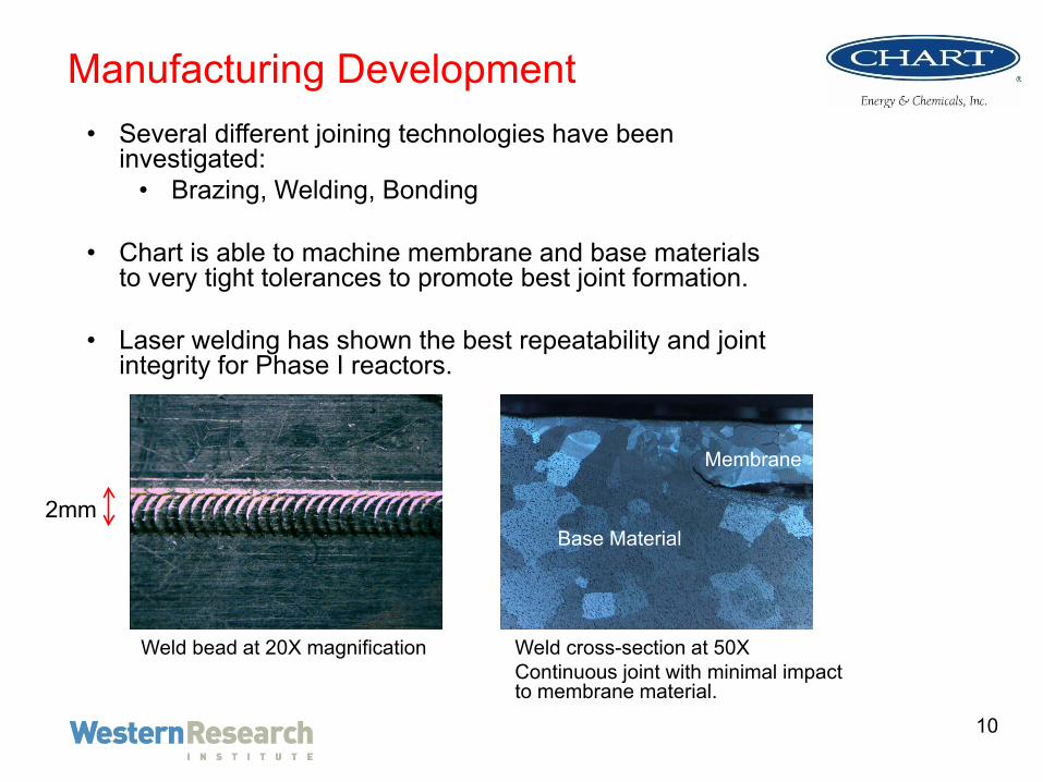
Manufacturing Development• Several different joining technologies have been
investigated:• Brazing, Welding, Bonding
• Chart is able to machine membrane and base materials to very tight tolerances to promote best joint formation.
• Laser welding has shown the best repeatability and joint integrity for Phase I reactors.
Weld bead at 20X magnification Weld cross-section at 50XContinuous joint with minimal impact to membrane material.
2mm
Membrane
Base Material
10

Membrane Structure
•nanoporous•support
•Pd nanoplugs
•nanoporous•support
•active•layer
0
100
200
300
400
500
600
.0 1.0 2.0 3.0 4.0 5.0
Distance, µm
Pd c
ount
s, a
.u.
0
500
1000
1500
2000
2500
3000
Al c
ount
s, a
.u.
Pdnanoplugs
Al (support)
Elemental profile of the cross-section confirms localization of active layer.
• Nanoporous ceramic support • Pore diameter 35-75 nm• Porosity 10-30% porosity• Thickness 50 to 200 µm
• Active layer of Pd-based nano-plugs• Plug diameter same as pore• Length from 0.25 to 2 µm
• Integrated onto Al rim
11

Membrane Performance• Extensive testing performed to date with AAO \ Pd
membranes.– Lab-sized (1”), scaled (2”x7”) membrane– Durable in broad T/P ranges
• up to 500 psi and 500°C for 1” membranes• up to 300 psi and 450°C for scaled membranes
• Permeance (at 350-400°C)– Over 1.5×10⁻³ mol/m2sPa0.5 for 1” (> 15 µm Pd-Cu
foil)– Up to 1×10⁻³ mol/m2sPa0.5 for scaled– Equivalent flux of 315 scfh/ft2
• Selectivity (H2/Ar)– > 1000 (lab), >100 (scaled)
• Reliability – T cycling from ambient to 400°C in hydrogen– No degradation, no embrittlement
12
0.0E+00
2.0E-04
4.0E-04
6.0E-04
8.0E-04
1.0E-03
1.2E-03
1.4E-03
1.6E-03
1.8E-03
0 10 20 30 40 50 60 70 80 90
H2
Perm
eanc
e (m
ol/m
2 /s/
Pa0.
5 )
Feed Pressure (psig)
Synkera 1"1" membranes
Pd-Cu foil
15 & 18 µm
25 µm
Synkera 2"x7"membranes
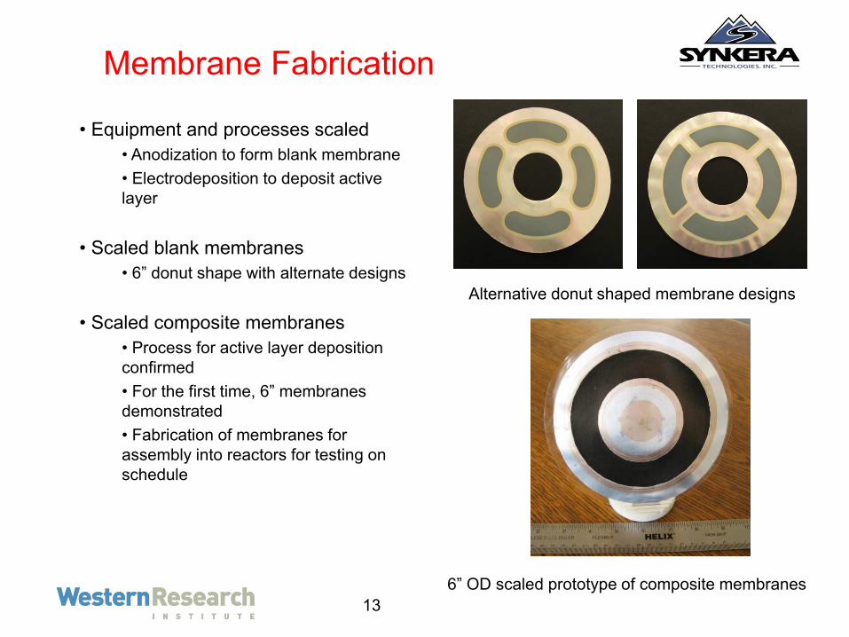
Membrane Fabrication
• Equipment and processes scaled• Anodization to form blank membrane• Electrodeposition to deposit active layer
• Scaled blank membranes• 6” donut shape with alternate designs
• Scaled composite membranes • Process for active layer deposition confirmed• For the first time, 6” membranes demonstrated• Fabrication of membranes for assembly into reactors for testing on schedule
Alternative donut shaped membrane designs
6” OD scaled prototype of composite membranes13
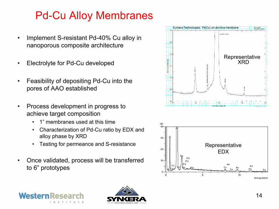
Pd-Cu Alloy Membranes
• Implement S-resistant Pd-40% Cu alloy in nanoporous composite architecture
• Electrolyte for Pd-Cu developed
• Feasibility of depositing Pd-Cu into the pores of AAO established
• Process development in progress to achieve target composition• 1” membranes used at this time• Characterization of Pd-Cu ratio by EDX and
alloy phase by XRD • Testing for permeance and S-resistance
• Once validated, process will be transferred to 6” prototypes
14
Representative XRD
RepresentativeEDX

15
Structural Water Gas Shift Catalyst
• Internal volumes of the reactor are to be filled with formed water gas shift catalyst designed to direct flow around the membrane surfaces.
• The simultaneous hydrogen extraction and WG shift improves the efficiency of both processes.
• The two substrates under active consideration are extruded porous alumina structures and monolithic honeycomb fitted to portion of the internal volume.
• Ideally the catalyst to membrane surface area ratio would be on the order of 5:1.

Structural Water Gas Shift Catalyst Concepts
16

Preliminary WGS Test Data
17
The activity of powder and the deposited catalysts in water-gas-shift reaction. Reaction temperature, 400°C, weight of the catalyst, 0.6 g, CO flow rate, 30 mL/min, and water 0.05 mL/min.

WRI’s 35 lb/hr Coal Gasifier
18

19
Future WorkAdditional funding of $1,100,000 has been awarded to the project team by the Wyoming Clean Coal Technology Fund. This budget will be used to expand the scope of Phase I efforts to include:
• additional catalyst development• larger scale membranes• higher pressure tests• economics of hydrogen production• preliminary Phase II scale design
The longer timeframe of this project will allow the team to transition to Phase II or, should Phase II not be awarded, to move towards commercialization.

Future Reactor Scale up
Schematics of devices for 2 lb/day and 100 lb/day
• 100 lb/day • 100 modules shown• Shell 96” long, 22” OD
• 2 - 4 lb/day• 4 modules shown• Shell 36” long, 8.625” OD
20

Membrane Scale-up Status• Membranes for portable PEM FC (NSF project)
– Material: pure Pd– Target output: 0.2-1.5 kg/day of H2 per module – Membrane active area: 5-35 sq. in. – Gen-1 prototypes produced and tested– Modules developed and validated with partners
• Membranes for syngas streams (Phase I)– Material: Pd-40%wt Cu (in development)– Target output: 1 kg/day of H2 per module – Membrane active area: 8-12 sq. in. – Gen-1 prototypes produced, testing in progress
• Membranes for industrial separation (Phase II)– Target output: 50-500 kg/day of H2 per module– Membrane active area: 50-200 sq. in. – Blank 11”x18” membranes demonstrated– Initial plate-and-frame module design available
Al rim 2” x 7”Active area 1”x 5”
6” ODActive area 8-12 sq. in.
Active area 8”x 14”Al rim 11”x 18”
21

22
• Increase catalyst stability and resistance to syngas impurities/poisons via inclusion of traps capable of regeneration.
• Further increase high temperature activity and stability to match increases in H2 membrane performance.
• Examine surface coatings for additional water gas shift activity.
Additional WGS Catalyst Plans

Emery Energy 10 ton/day Gasifier
23

24
Conclusions• The 2 lb/day device is designed as a modular stainless steel pressure
vessel containing both stacked hydrogen separation membranes and a structural water gas shift catalyst.
• The separation membranes are composite pieces using anodized alumina as a regular porous structure to hold thin palladium alloy plugs.
• The advantages of the composite membranes include the resistance to cracking, the presence of a joinable rim, and the small amount of palladium alloy required.
• The final palladium copper alloy will be chosen for sulfur resistance.
• The project is on schedule to produce and test the Phase I device under NETL protocols and coal derived syngas.

25
Project Summary
Approach: The goal is to produce a 2 lb/day hydrogen device including design, reactor fabrication, catalyst development, membrane fabrication and testing under coal derived syngas.
Conclusions:A stainless steel pressure vessel with stacked donut shaped composite membranes and ceramic WGS catalyst is under construction. The Phase I project is on schedule.
Future Work:The team has been awarded addition non – DOE funding to expand and transition the project toward Phase II goals of a 100 lb/day hydrogen device.

Technical Backup Slides

Concept Utilizing Rectangular Membranes
This design integrates catalyst supports and uses catalyst structures to direct flow across the membrane surfaces.
27

28
WGS Catalyst Development Future Work
New methods of depositing the catalyst on the monoliths should involve a single step that deposits sufficient mass in the correct phase to maintain catalyst activity and stability. Single step liquid-phase impregnation is the most likely candidate. The research will focus on determining the optimum precursor chemicals and solvents that will permit sufficient solution concentration to deposit the required amount of catalyst.
The optimum thermal treatment and activation methods will be sought.
Methods for preventing pore mouth plugging will be developed, such as modifying the liquid-phase chemistry with addition of surfactants, as part of the catalyst loading and pretreatment methods.
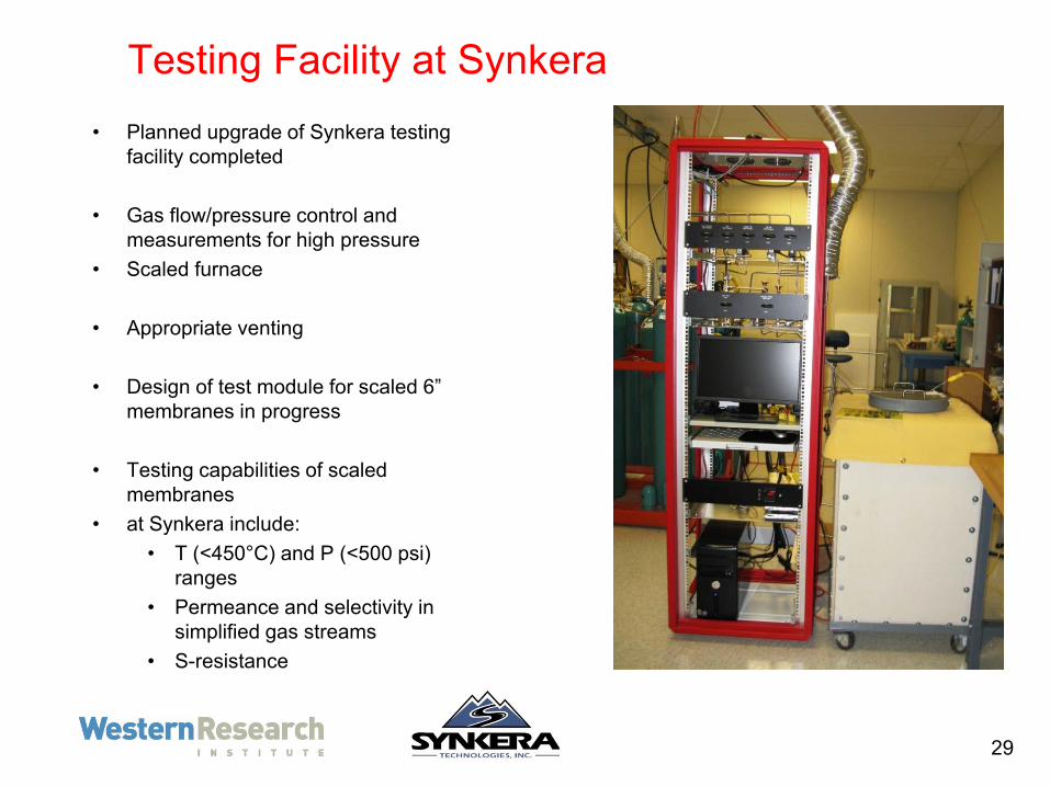
Testing Facility at Synkera• Planned upgrade of Synkera testing
facility completed
• Gas flow/pressure control and measurements for high pressure
• Scaled furnace
• Appropriate venting
• Design of test module for scaled 6” membranes in progress
• Testing capabilities of scaled membranes
• at Synkera include:• T (<450°C) and P (<500 psi)
ranges• Permeance and selectivity in
simplified gas streams• S-resistance
29