Pilot-Operated Regulating Valves · 2017-05-02 · Pilot-Operated REGULATORS Pressure Pilot Ductile...
43
199 Pilot-Operated Regulating Valves Pilot-Operated REGULATORS www.watsonmcdaniel.com •• 428 Jones Boulevard • Limerick Airport Business Center • Pottstown PA • 19464 •• Tel: 610-495-5131
Transcript of Pilot-Operated Regulating Valves · 2017-05-02 · Pilot-Operated REGULATORS Pressure Pilot Ductile...

199
Pilot-Operated Regulating Valves
Pilot-Operated
REG
ULA
TORS
www.watsonmcdaniel.com •• 428 Jones Boulevard • Limerick Airport Business Center • Pottstown PA • 19464 •• Tel: 610-495-5131

200
HD Main Valve is used in conjunction with the appropriatePilot(s) to control Steam Pressure or Process Temperature
Most Common HD Pilots
PP & PP5PRESSURE
Spring-Loaded
Main Valve & Pilots
HD Main ValveDuctile Iron
HD Regulator with PP-PRESSURE Pilot
(See Page 210)
HD Regulator with PP-PRESSURE Pilot & PT-TEMPERATURE Pilot
(See Page 214)
HD Regulator with PT-TEMPERATURE Pilot
(See Page 214)
HD Regulator with PA-Air Loaded PRESSURE Pilot
(See Page 218)
HD Regulator with PTRP- TEMPERATURE Pilot
(See Page 222)
PSOn/Off
(Solenoid)
PTTEMPERATURE
Liquid Filled
PAPRESSUREAir-Loaded
Pilo
t-O
pera
ted
REG
ULA
TORS
HD Regulating Valve & Pilots Table of Contents
www.watsonmcdaniel.com •• Pottstown PA • USA • Tel: 610-495-5131

201
PBPBACK PRESSURE
PDPDIFFERENTIAL
PRESSURE
PTRPTEMPERATURE
PTR & PTLTEMPERATURE
Controllers
HSP Series Pressure Regulators • Cast Steel 231
The Watson McDaniel HSP Pilot-Operated Pressure Regulating Valve is constructed of Cast Carbon Steel for higher pressure and temperature ratings when compared to ductile iron.
HD Series Pilot-Operated Regulating Valves - Introduction 202-207
Main Valve for HD Regulators • Ductile Iron 208-209
Pilots for HD Regulators 210-230
PP & PP5-Pressure Pilots Spring-loaded pressure pilots for general service steam pressure reducing. 210
PBP-Back Pressure Pilot For controlling upstream pressure of the HD Regulator. 212
PT-Temperature Pilot General purpose liquid-filled temperature pilot used when heating 214liquids to a desired temperature.
PA-Pressure Pilot Air-loaded Pressure Pilot can be used instead of spring-loaded PP pilots 218(Air-Loaded) for pressure regulation in remote installations. Also used in conjuction with
PTR & PTL temperature controllers.
PS-Solenoid Pilot Solenoid Pilot can be used in conjunction with any of the listed pilots for 222electrical on/off control of HD Regulators.
PTRP Temperature Pilot Special purpose vapor tension temperature pilot for increased sensitivity 224and reduced reaction time when controlling temperature of liquids and air.
PTR & PTL Temperature These temperature controllers have a wider temperature span than the 228Controllers PT temperature pilot. They are used in conjunction with the PA-Air Pilot to
deliver an air signal to the HD valve.
PDP-Pilot Differential Pressure Pilot with two separate sensing ports for maintaining 230differential pressure between steam and an alternate medium.
Other HD Pilots
Pilot-Operated
REG
ULA
TORS
HD Regulating Valve & PilotsTable of Contents
Noise Attenuators for HD & HSP Regulators: Reduces noise in pressure reducing applications 236
Capacity Charts for HD & HSP Regulators 240
Page No.
Tel: 610-495-5131 • Pottstown PA • USA •• www.watsonmcdaniel.com
Combination Pilots
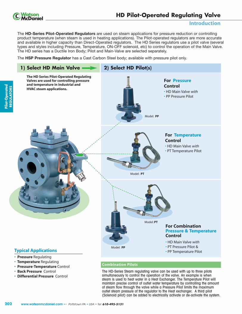
The HD-Series Steam regulating valve can be used with up to three pilotssimultaneously to control the operation of the valve. An example is whensteam is used to heat water in a Heat Exchanger. The Temperature Pilot willmaintain precise control of outlet water temperature by controlling the amountof steam flow through the valve while a Pressure Pilot limits the maximumoutlet steam pressure of the regulator to the Heat exchanger. A third pilot(Solenoid pilot) can be added to electrically activate or de-activate the system.
202
For PressureControl• HD Main Valve with• PP Pressure Pilot
For TemperatureControl• HD Main Valve with• PT Temperature Pilot
For Combination Pressure & Temperature Control• HD Main Valve with• PT Pressure Pilot &• PP Temperature Pilot
The HD-Series Pilot-Operated Regulators are used on steam applications for pressure reduction or controllingproduct temperature (when steam is used in heating applications). The Pilot-operated regulators are more accurateand available in higher capacity than Direct-Operated regulators. The HD Series regulators use a pilot valve (severaltypes and styles including Pressure, Temperature, ON-OFF solenoid, etc) to control the operation of the Main Valve.The HD series has a Ductile Iron Body; Pilot and Main-Valve are selected separately.
The HSP Pressure Regulator has a Cast Carbon Steel body; available with pressure pilot only.
1) Select HD Main Valve 2) Select HD Pilot(s)
The HD Series Pilot-Operated RegulatingValves are used for controlling pressureand temperature in industrial and HVAC steam applications.
Model: PP
Model: PT
Model: PP
Model: PT
Typical Applications• Pressure Regulating• Temperature Regulating• Pressure-Temperature Control• Back Pressure Control• Differential Pressure Control
Pilo
t-O
pera
ted
REG
ULA
TORS
HD Pilot-Operated Regulating ValveIntroduction
www.watsonmcdaniel.com •• Pottstown PA • USA • Tel: 610-495-5131

203
HD Main Valvewith
PP-Pressure Pilot
HD Main Valvewith
PT-Temperature Pilot
Controlling TemperatureWhen steam is used on heatingapplications, several choices of pilotsare available. The PT pilot (mostcommon) is referred to as a “solidliquid fill” and contains a temperatureprobe connected by a length ofcapillary tubing to a bellows in thepilot valve. When the temperature bulbis heated the liquid inside the probeexpands the bellows and closes off thepilot valve. PTRP pilot operates in asimilar fashion except this style isreferred to as a vapor tension unit. The PTL temperature controller uses abi-metal element to sense temperatureand deliver an appropriate air signalto a PA air pilot that controls theoperation of the HD main valve.
Reducing PressureSeveral choices of pilot valves canbe used for pressure reduction onsteam applications. The opening of the pressure pilot controls theoperation of the Main Valve. The PP & PP5 are referred to as springloaded pressure pilots because anadjustable control spring is used to apply the opening force to thepilot valve. Pressure adjustmentscrew is located on top of pressurepilot. The PA pilot is referred to asan Air Loaded pressure pilot becauseAir Pressure is used to apply theopening force to the pilot valve. The PA pilot allows for convenientand remote adjustment of steampressure using a small air regulator.
HD Main Valvewith
PP-Pressure Pilotand
PT-Temperature Pilot
Controlling Temperature& Limiting Pressure to aMaximum ValueThe PT & PP Pilot combination is used when it’s required tocontrol temperature whilelimiting downstream pressureto a maximum value. When thePT & PP Pilot combination isused, the downstream pressure islimited to a maximum setting bythe pressure pilot, while thetemperature pilot maintains thecorrect temperature of the process.
steaminlet
HD MainValve
PP Pressure
Pilotreduced
outletpressureinlet
pressure
steaminlet
HD MainValve
PTTemperature
Pilot
tempprobe
heatexchanger
hot waterstorage tank
PressurePilotHD
MainValve
TemperaturePilot
tempprobe
heatexchanger
hotwateroutlet
coldwaterinlet
Pilot-Operated
REG
ULA
TORS
steaminlet
reduced outlet pressureinlet
pressure
HD Pilot-Operated Regulating ValveIntroduction • Typical Applications
Tel: 610-495-5131 • Pottstown PA • USA •• www.watsonmcdaniel.com
204
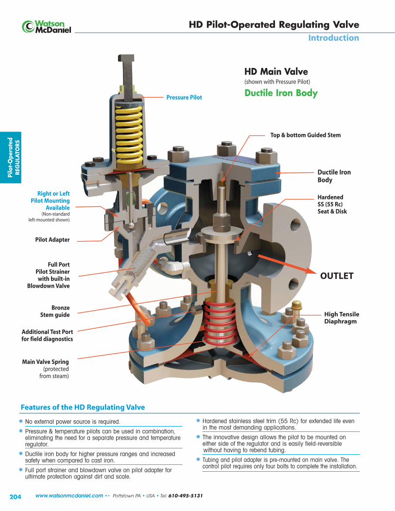
Ductile IronBody
Right or LeftPilot Mounting
Available(Non-standard
left-mounted shown)
Hardened SS (55 Rc) Seat & Disk
Main Valve Spring (protected
from steam)
Full Port Pilot Strainer with built-in
Blowdown Valve
Bronze Stem guide High Tensile
Diaphragm
OUTLET
• No external power source is required.
• Pressure & temperature pilots can be used in combination,eliminating the need for a separate pressure and temperatureregulator.
• Ductile iron body for higher pressure ranges and increasedsafety when compared to cast iron.
• Full port strainer and blowdown valve on pilot adapter forultimate protection against dirt and scale.
HD Main Valve (shown with Pressure Pilot)
Pilo
t-O
pera
ted
REG
ULA
TORS
Pressure Pilot Ductile Iron Body
• Hardened stainless steel trim (55 Rc) for extended life evenin the most demanding applications.
• The innovative design allows the pilot to be mounted oneither side of the regulator and is easily field-reversiblewithout having to rebend tubing.
• Tubing and pilot adapter is pre-mounted on main valve. Thecontrol pilot requires only four bolts to complete the installation.
Features of the HD Regulating Valve
HD Pilot-Operated Regulating ValveIntroduction
Pilot Adapter
Additional Test Portfor field diagnostics
Top & bottom Guided Stem
www.watsonmcdaniel.com •• Pottstown PA • USA • Tel: 610-495-5131

205
Pressure ControlWhen controlling pressure, there are several options you can use for a pilot. The PP-Pilot and the PP5-Pilot are both spring-adjusted pressure pilots. The PP-Pilot is used on general-purposepressure reducing applications and the PP5-Pilot is used whenhigher accuracy is required. The PA-Pilot is air controlled andallows for easi er and remote a djus tment of steam pressure.
Temperature ControlSeveral choices of pilot valves can be used for temperature controlwhen steam is used on heating applications. The PT style pilot(most common) is referred to as a “solid liquid fill” and containsa temperature probe connected by a length of capillary tubing toa bellows in the pilot valve. When the temperature bulb is heatedthe liquid inside the probe expands the bellows and closes off thepilot valve. PTRP pilot operates in a similar fashion except thisstyle is referred to as a vapor tension unit. The PTL temperature controller uses a bi-metal element to sensetemperature and deliver an appropriate air signal to a PA air pilotthat controls the operation of the HD main valve.
Temperature-Pressure ControlThe PP & PT-Pilot combination is used when it is desirable tocontrol both the pressure and temperature of a system with onlyone regulating valve. The unique features of this modular valveallow this to be accomplished quite easily. When the PP & PT-Pilotcombination is used, the downstream pressure is limited to amaximum setting by the pressure pilot, while the temperature pilotmaintains the correct temperature.
On-Off OperationElectrical On-off control of the regulator is possible by using thePS-Solenoid Pilot. The PS-Pilot allows the regulator to be shut offor turned on electrically. Normally the regulator is equipped witheither a PP-Pressure Pilot or PT-Temperature Pilot in addition to the PS-Solenoid Pilot.
Back PressureWhen controlling the back pressure in a steam system, the BP-Pilot is used in conjunction with the HD-Series Regulator. This controls the pressure on the upstream side of the regulator.
Differential Pressure The PDP-Pilot is used when trying to balance two different mediasources that are being blended.
Stainless Diaphragm OptionThe HD regulator is supplied standard with a high tensile strengthPhosphor Bronze diaphragm which has been determined thruexperience and testing to be the absolute best diaphragm materialchoice for steam applications. Stainless Steel diaphragms areoffered as an option because certain industry specifications havebeen written requiring stainless steel. Note: Stainless steel is proneto work hardening and will not last as long as phosphor bronze;only use if required by the specification to do so.
Stainless Tubing OptionCopper tubing is supplied as standard. Copper tubing offers excellent corrosion resistance and is easy to bend and manipulateand normally outlasts the life span of the valve. Stainless Steeltubing is offered as an option.
Reduced port trim Option:Regulators should be sized to meet the application not to fit the pipesize. Over sizing a regulator may cause overshoot which leads toerratic pressure or temperature control often referred to as “hunting.”A valve with reduced port trim has a reduced seat and disc size for a given pipe size, (refer to capacity charts).
Low pressure (differential and inlet) Option:Regulators require a minimum Inlet pressure as well as a minimumpressure drop across the valve to operate properly. The HDStandard Main valve requires a minimum inlet pressure of 15 PSIGand minimum differential pressure of 10 PSI. The Low PressureMain valve requires 5 PSIG minimum inlet pressure and 3 PSIminimum differential pressure. Low pressure main valve uses aEPDM diaphragm.
Typical Configurations
The HD Series Pilot-Operated Regulating Valve was designed for extremely accurate control of temperature and pressurein steam service applications. The HD-Series is made of Ductile Iron for extended pressure and temperature ratings whencompared to ca st iron. S everal different control pilots can be mounted to the valve to control pressure, temperature, or acombination of both. When two or more pilots are used tog eth er (both a pressure and a temperature pilot) an additional pilotadapter for the second pilot is required (must indicate when ordering). The most common pilots are the PP-Pilot for pressurereducing, and the PT-Pilot for temperature control. The Standard Main Valve is used for an inlet steam pressure range of 15 -300 PSI. The Low-pressure Main Valve contains a dif ferent main valve sprin g and is available for an inlet pressurerange of 5 -20 PSI. The Main Valve and Pilot are purchased separately.
PP & PP5PRESSURE
PilotSpring-Loaded
PTTEMPERATURE
PilotLiquid Filled
PAPRESSURE
PilotAir-Loaded
PBPBACK
PRESSUREPilot
PDPDIFFERENTIAL
PRESSUREPilot
PTRPTEMPERATURE
PilotVapor Tension
PSON/OFF
(Solenoid)
Pilot-Operated
REG
ULA
TORS
HD Pilot-Operated Regulating ValveIntroduction
Tel: 610-495-5131 • Pottstown PA • USA •• www.watsonmcdaniel.com

206
Pilo
t-O
pera
ted
REG
ULA
TORS
HD Main ValvewithPP-Pressure PilotSpring-Loaded
HD Main ValvewithPT-Temperature Pilot
Shown with PP Pressure control Pilot. Spring-loaded pressure pilots are the mosttypical method of controlling downstream pressure in Steam Systems. Adjustmentscrew on top of pilot controls downstream steam pressure.
Shown with Temperature control Pilot: The PT Temperature Pilot will control the flowof steam flowing through the HD valve based on the temperature of the sensing bulb.The liquid-filled sensing Bulb is available in standard 8 ft and 15 ft capillary lengths.Other lengths available.
HD Main ValvewithPA-Pressure PilotAir-Loaded
HD Main ValvewithPS On/Off ControlSolenoid Pilot
Shown with Air-loaded pressure control pilot. Air-loaded pressure pilots are used toreduce and control pressure in steam systems. They are used as an alternative to themore common spring-loaded pilot. The PA Air-loaded pressure pilot allows for remoteadjustment of the valve using a small air regulator to alter the air pressure to the topof the pilot.
Shown with PS ON-OFF(solenoid Pilot) control pilot: The PS ON-OFF (solenoid) Pilotallows for the HD valve to be opened and closed using an electrical switch to activate a small solenoid valve. The PS Pilot can be used for system automation or as a safetyshut down device. The ON-OFF pilot is most often used in conjunction with a Pressureor Temperature control pilot.
HD Pilot-Operated Regulating ValveHD Regulator & Pilot Combinations
www.watsonmcdaniel.com •• Pottstown PA • USA • Tel: 610-495-5131

207
Pilot-Operated
REG
ULA
TORS
HD Main Valvewith• PP-Pressure Pilot• PS1 On/Off Control
Solenoid Pilot
HD Main Valvewith• PT-Temperature Pilot• PS1 On/Off Control
Solenoid Pilot
HD Main Valvewith• PT-Temperature Pilot• PP-Pressure Pilot
HD Main Valvewith• PP-Pressure Pilot• PT-Temperature Pilot• PS1 On/Off Control
Solenoid Pilot
The PT Temperature Pilot will maintain the proper flow of steam through the mainvalve to keep the process it’s controlling at the proper temperature. The PP pressurePilot will LIMIT the downstream pressure to a maximum value. This combination ofPilots is very convenient when the Steam Pressure in the supply line is greater thanthe maximum pressure allowed to the process heat exchanger. This eliminates usinga separate Pressure reducing valve prior to the temperature control valve.
NOTE: When two or more pilots are used on the same valve: An additional Pilot Adapter for Second Pilot is required: Use part number: BADAPTER
The PP Pressure Pilot will maintain the desired downstream set pressure as long asthe PS ON-OFF (solenoid) Pilot is in the ON position. Available in either Normally-ONor Normally-OFF configuration; an electrical signal turns valve OFF or ON.
The PT Temperature Pilot will maintain the proper flow of steam through the main valve to keep the process it’s controlling at the proper temperature as long as the PS ON-OFF (solenoid) Pilot is in the ON position. Available in either Normally-ON or Normally-OFF configuration; an electrical signal turns valve OFF or ON.
The PT Temperature Pilot will maintain the proper flow of steam through the mainvalve to keep the process it’s controlling at the proper temperature as long as thePS ON-OFF (solenoid) Pilot is in the ON position. The PP Pressure Pilot will LIMITthe downstream pressure to a maximum value.
NOTE: When two or more pilots are used on the same valve: An additional Pilot Adapter for Second Pilot is required: Use part number: BADAPTER
HD Pilot-Operated Regulating ValveHD Regulator & Pilot Combinations
Tel: 610-495-5131 • Pottstown PA • USA •• www.watsonmcdaniel.com

xy(
)*+,-./0123-14 56789:;/5<z{�|3*?�@3+A1�¦{>}-*+1��2,? z{�<12*1B51=>+3-,2B��)*+,-./0123-14�51=>+3-*?=�@3+A1B
LQ§V©NPPVYRQNP thsª¢s¤¢� «¬®S¤£tt¤£ °VQ]MR±������������� ±������������� �²�³�µ�¶··���± �µ�·���±p¹º�uTf »¼½¾¿½À »¼½¾¿½À½Á ¹ÃÄú�uTf »¼½¾Å½À »¼½¾Å½À½Á ¹Ãpº�uTf »¼½¾Æ½À »¼½¾Æ½À½Á ÄÇpº�pqÇÈ�v�É »¼½¾Æ½Ê¾ËÌ »¼½¾Æ½Ê¾Ë̽Á Äppº�ÄÇÇÈ�v�É »¼½¾Æ½ÊÅÌÌ »¼½¾Æ½ÊÅÌ̽Á ÄÃppú�uTf »¼½¾Ë½À »¼½¾Ë½À½Á qÇpp¹º�uTf »¼½¾Í½À »¼½¾Í½À½Á qppp¹º�pqÇÈ�v�É »¼½¾Í½Ê¾ËÌ »¼½¾Í½Ê¾Ë̽Á qÃpp¹º�ÄÇÇÈ�v�É »¼½¾Í½ÊÅÌÌ »¼½¾Í½ÊÅÌ̽Á Îǹº�uTf »¼½¾Ï½À »¼½¾Ï½À½Á й¹º�pqÇÈ�v�É »¼½¾Ï½Ê¾ËÌ »¼½¾Ï½Ê¾Ë̽Á oǹº�ÄÇÇÈ�v�É »¼½¾Ï½ÊÅÌÌ »¼½¾Ï½ÊÅÌ̽Á o¹¹p¹º�pqÇÈ�v�É »¼½¾Ñ½Ê¾ËÌ »¼½¾Ñ½Ê¾Ë̽Á pÇq¹p¹º�ÄÇÇÈ�v�É »¼½¾Ñ½ÊÅÌÌ »¼½¾Ñ½ÊÅÌ̽Á pÇÒĺ�pqÇÈ�v�É »¼½¾Ó½Ê¾ËÌ »¼½¾Ó½Ê¾Ë̽Á pqÇĺ�ÄÇÇÈ�v�É »¼½¾Ó½ÊÅÌÌ »¼½¾Ó½ÊÅÌ̽Á pqoú�pqÇÈ�v�É »¼½¿Ì½Ê¾ËÌ »¼½¿Ì½Ê¾Ë̽Á ¹ÄÇú�ÄÇÇÈ�v�É »¼½¿Ì½ÊÅÌÌ »¼½¿Ì½ÊÅÌ̽Á ¹qÇκ�pqÇÈ�v�É »¼½¿¿½Ê¾ËÌ »¼½¿¿½Ê¾Ë̽Á ÃqÇκ�ÄÇÇÈ�v�É »¼½¿¿½ÊÅÌÌ »¼½¿¿½ÊÅÌ̽Á Ãй
6ÔÕ��5Ö00×5Ö�Ø��1�Ù��Ú��0#��1zÛÜ�ïêñ�îëêííùëê;�ÝÞßà�áâãäåæõ�ôïê�çðöêï�èðöê;éêÞëßÞìÞíá�������������������������������������������������������������������������������������������������������������������î�������������������������������ï� WV�\_UR�PXalVUg�w¡s¢sSh£¤xðñòóôõö�÷�øùùúûö�� �����NO�TUVWWXUV��_QP��_ZkVg�� «S�VXYV�TNUR��_ZkVWg� �¢¤LR_QPZVWW�LRVVZ�jQ_\MU_]ag� tt¢LR_QPZVWW�LRVVZ��RVUP_Z�fXlQP]g tth�VmXQUV�cNU�WVYNP_Ub�TQZNRg ¡s¢sSh£¤wuNR�UVmXQUV�cNU�LNZVPNQ�TQZNRx
�NVZ�©NVW�lVZNO�_UV�cNU�ij��_QP��_ZkV�ru��[��©NPRUNZ�TQZNR�aXWR�lV�NUVUVWV\_U_RVZb[�°MVP�RON�NU�aNUV�\QZNRW�_UV�XWV�NP�RMV�W_aV�k_ZkV��_�\QZNR�__\RVU�aXWR�lV�NUVUV�_ZWN[� WV�T_UR�uXalVU�ndjdTf�[ ôùú���ôùú��ôõ�ó��û�òóôõ����ûò������ �������������������� ����������������������������������������� �����������î������ﻼ vXZZ�TNUR ¾¿�p¹º� À uTf wp¹º�¹ºx ��¼ LL�jQ_\MU_]a»¼� �VXYV�TNUR ¾Å Äú� �� nLTf�����������wp¹º�¹ºx ���� LL��RVUP_Z�fXlQP]¾Æ pº� ʾËÌ pqÇÈ�v�É����wpº��κx Á �NO�TUVWWXUV��_QP��_ZkV�L\UQP]¾Ë ppú ÊÅÌÌ ÄÇÇÈ�v�É����wpº�κx OQRM�Tj��jQ_\MU_]a¾Í pp¹º¾Ï ¹º�¾Ñ ¹p¹º¾Ó ĺ¿Ì ú¿¿ κ
����������������������������� �����px�»¼½¾Ë½À�wij�LVUQVW��_ZkV�OQRM�ppúfMUV_V��uTf�YNPPVYRQNPWx�¹x»¼�½¾Í½Ê¾ËÌ��wij�LVUQVW��_ZkV���VXYV�TNUR�OQRM��pp¹º�pqÇÈ�vZ_P]V�YNPPVYRQNPWx�Äx�»¼½¿Ì½ÊÅÌ̽����wij�LVUQVW��_ZkV�OQRM�ú��ÄÇÇÈ�vZ_P]V�YNPPVYRQNPW�!�LL��RVUP_Z�RXlQP]x�
0!("8(58�Ø��1�Ù��Ú��0#��1zÛÜ�ïêñ�îëêííùëê;ëÝÞ#àà�áâãäåæõ�ôïê�çðöêï�èðöê;éêÞëßÞìLIQ�°LPRC �ö�·ºô·Á�GI CJ $%&'�(�)'�XQQCSKIXQJ *òù+�$%&'�ö�&',û-+�$'�ö�)'�XUY�LKCHILP �¼�¶ô�·�.º¾À_��L][��WCHLKIQN�_HCJJOHC /00�ò�.-ECJINQ�_HCJJOHC1 �_A�������2ë3�Ü456�7�8ë39�æACMWCHLKOHC�LKIQNJ�� �²�:�;®��<ë3�Ü456�7�ë889�æA\1_ \ ���:�;®��2ë3�Ü456�7�8ë39�æ_IPXK�MXOQKIQNJOHZLSC
ðûùúûóõ��=õöòû�>òóôõö�
CCCDCEFGHIJKLEIMNODKHJPPiUggXgUjV�ie�PÔÕe�PnW[o�pqrstuvsvqwq
uNRVg�vNU�aNUV�RM_P�NPV�r\RQNP��YNalQPV�WXccQ�VW[�����������?µ��@�

209
Pilot-Operated
REG
ULA
TORS
HD Valve with Temperature Pilot
Model Code for Main Valve: HD-17-F150(2” HD Series Valve with 150# Flanges)
Model Code for Pilot: PP-B(Pressure Pilot with 20-100 PSIG Range)
Model Code for Main Valve: HD-17-F150(2” HD Series Valve with 150# Flanges)
Model Code for Pilot: PTU-14-8(Temperature Pilot (100-160˚ F) with 8 Ft. Capillary)
HD Valve with Pressure Pilot
Model Code for Main Valve: HD-17-F150(2” HD Series Valve with 150# Flanges)
Model Code for Pilot: PP-B (Pressure Pilot with 20-100 PSIG Range)
Model Code for Pilot: PTU-14-8(Temperature Pilot (100-160˚ F) with 8 Ft. Capillary)
Model Code for Secondary Pilot Adapter*: BADAPTER
HD Valve with Pressure & Temperature Pilots
* If 2 Pilots are used on the same valve, a SecondaryPilot Adapter is required.
AFLG
ANPT
C
B
FLOW
D
HD SeriesRegulators Pilot-Operated Regulating Valves
Ordering Instructions: HD Series Regulator with a Pilot
Model Code for Main Valve: HD-19-F150 HD Series Valve with 3” 150# Flanges Model Code for Pilot: PP-B Pressure Pilot, 20-100 PSIG (Blue spring color)
HD Main Valve • Ductile Iron
Standard pilot mounting is on the right side of the regulator when looking into the outletport (as shown). Pilot mounting on HD regulators are field-reversible.
Option: Stainless diaphragms and external tubing - consult factory
HD-Ser ies DIMENSIONS – inches
(A) Face-To-Face Weight (lbs)Size NPT 150# 300# B C D NPT 150# 300#1/2” 43/8 51/2 33/8 61/2 183/4” 43/8 51/2 33/8 61/2 181” 53/8 51/2 6 61/4 31/2 7 23 40 45
11/4” 61/2 73/8 47/8 83/4 4311/2” 71/4 67/8 73/8 73/8 47/8 83/4 43 55 60
2” 71/2 81/2 9 81/4 53/8 107/8 65 75 8521/2” 93/8 10 9 53/4 113/4 100 105
3” 10 103/4 87/8 63/4 131/4 130 1454” 117/8 121/2 107/8 71/2 143/4 215 2356” 151/8 16 141/8 10 193/4 420 470
MATERIALSBody Ductile IronCover Ductile IronGasket Grafoil/GarlockCover Screws SteelPilot Adapter Ductile Iron/Cast SteelScreen Stainless SteelTubing CopperValve Seat Hardened SST (55Rc)Valve Disc Hardened SST (55Rc)Diaphragm Phosphor Bronze (standard)
EPDM (Low Pressure Main Valve)
OPERATING PRESSURES
Inlet Pressure Range: (for Main Valve):15 PSIG (Standard Main Valve)5 PSIG (Low-Pressure Main Valve)
Minimum Differential Pressure (for Main Valve):*10 PSI (Standard Main Valve)3 PSI (Low-Pressure Main Valve)
* Not required for Temperature Pilot applications
Tel: 610-495-5131 • Pottstown PA • USA •• www.watsonmcdaniel.com

210
Typical Applications
The PP & PP5 Pressure Pilots are used with the HD Regulator tocontrol steam pressure in steam mains or for process equipment.Pilot-operated regulators maintain constant downstream pressureeven when the inlet pressure to the valve fluctuates or steam usagevaries. The PP-Pressure Pilot is adequate for controlling pressurein most industrial applications. For increased accuracy use thePP5 Pilot.
PP-Pressure Pilot (Standard) 1.0 PSIG accuracyPP5-Pressure Pilot (Special Applications) 0.5 PSIG accuracy
Features• The PP-Pilot can maintain downstream pressure to ±1 PSIG• PP5-Pilot can maintain downstream pressure to ±0.5 PSIG• Choices of three overlapping pressure ranges• Pilot is easily installed on pilot adapter using four bolts,
no tubing connections are required• Full port strainer and blowdown valve on pilot adapter for
protection of pilot from dirt and scale• Solid floating diaphragm is more failure resistant• Watson McDaniel's pilots can be used with other
manufacturers’ regulators
MATERIALS for HD Main ValveBody Ductile IronCover Ductile IronGasket Grafoil/GarlockCover Screws SteelPilot Adapter Ductile Iron/Cast SteelScreen Stainless SteelTubing CopperValve Seat Hardened SST (55 Rc)Valve Disc Hardened SST (55 Rc)Diaphragm Phosphor Bronze
PP & PP5 PilotsRegulators Pilots for HD Regulating Valves HD Series
MATERIALS for PP Pressure Pilot
PP Pilot Body WCb 216 Cast SteelPP5 Pilot Body Cast IronHead & Seat Gasket 302 SSDiaphragm Phosphor BronzeHead & Seat Assembly Hardened SST (55 Rc)
Pressure Regulating with PP & PP5 Spring-loaded Pilot
91/2
5
Sensing Line
Connection1/4” NPT
12
8 “PP5”
“PP”
Units: inches
Reduced Pressure Range Model Spring WeightPSI Code Color lbs
PP-Pressure Pilot (for Standard Industrial Applications) 1.0 PSIG accuracy
3-25 PP-Y Yellow 1020-100 PP-B Blue 1080-200 PP-R Red 10
PP5-Pressure Pilot (Special Applications) 0.5 PSIG accuracy
1-10 PP5-Y* Yellow 2510-25 PP5-B* Blue 25
* A Spacer (model # BAP-SPACE) is required when using PP5 Pressure Pilots on a 3” & 4” HD Main Valve.
Example: PP-B Pilot at 20-100 PSIG
Pressure Pilot (Standard: 1.0 psig accuracy) PP(High-accuracy: 0.5 psig accuracy) PP5
Pilot Body Material Cast Steel Max Inlet Pressure 300 PSIGReduced Outlet Pressure Range 3-200 PSIGInlet Pressure Range(with HD Standard main valve) 15-300 PSIG(with HD Low-Pressure (LP) main valve) 5-20 PSIG
Minimum Differential Pressure(with HD Standard main valve) 10 PSI(with HD Low-Pressure (LP) main valve) 3 PSI
Model Code for Main Valve: HD-17-F150(2” HD Series Valve with 150# Flanges)
Model Code for Pilot: PP-B(Pressure Pilot with 20-100 PSIG Range)
HD Main ValvewithPP-Pressure Pilot
Pilo
t-O
pera
ted
REG
ULA
TORS
Options
• Pressure pilot can be used with temperature pilot to eliminate the need for two separate regulators
• Solenoid pilot can be added for remote on/off control of regulator
PressureAdjusting
Screw AdjustingSpring
www.watsonmcdaniel.com •• Pottstown PA • USA • Tel: 610-495-5131

211
E
B
C
D
Standard PP-Pilot = 5”PP5-Pilot = 8”
PP & PP5 PilotsRegulators Pilots for HD Regulating Valves HD Series
DIMENSIONS HD-Ser ies – inches
Face-To-Face Weight (lbs)Size NPT 150# 300# B C* D E** NPT FLG1/2” 43/8 - - 51/2 117/8 61/2 73/4 18 -3/4” 43/8 - - 51/2 117/8 61/2 73/4 18 -1” 53/8 51/2 6 61/4 117/8 7 73/4 23 35
11/4” 61/2 - - 73/8 117/8 83/4 81/4 43 -11/2” 71/4 67/8 73/8 73/8 117/8 83/4 81/4 43 60
2” 71/2 81/2 9 81/4 117/8 107/8 81/2 65 8521/2” - 93/8 10 9 117/8 113/4 81/2 - 105
3” - 10 103/4 87/8 117/8 131/4 91/2 - 1454” - 117/8 121/2 107/8 117/8 143/4 101/2 - 2356” - 151/8 16 141/8 121/2 193/4 113/4 - 470
For PP5 Pilot: * For sizes 1/2” to 11/2” add 21/2” to “C” dimension; For sizes 2” to 6” add 5” to “C” dimension.
** Add 11/2” to “E” dimension for all sizes.
Pressure Regulating with PP & PP5 Spring-loaded Pilot
Reducing PressureThe PP-Pilot and the PP5-Pilot are both spring-adjustedpressure pilots. The PP-Pilot is used on typical general-purpose pressure reducing applications. The PP5-Pilot isused when higher accuracy is required and is capable ofmaintaining a control pressure window of less than 1 PSI.
steaminlet
HD MainValve
PP Pressure
Pilot reduced outlet
pressureinletpressure
Pilot-Operated
REG
ULA
TORS
How it WorksThe Pressure Pilot controls the operation of the HD Regulator. The sensing line connects the pressure pilot to the downstream sideof the regulator. Pressure in the sensing line applies an upward force to the pilot diaphragm to compress the adjustment spring.When system pressure equals set point, the diaphragm moves upwards against the force of the adjusting spring, closing pilot valve.When the pilot valve is shut, steam cannot pass thru to the underside of the regulator diaphragm, closing the regulator. When the steam pressure falls below its set point, the pilot valve opens allowing steam to lift the main valve diaphragm which opens up the regulating valve.
Pilot Diaphragm
Downstream PressureSensing Line
HighPresssure
Diaphragm
PressureOpensMain Valve
BleedOrifice
PilotAdapter
Pilot valve opens and closesdepending on downsteam pressure
(shown open)
MainValve
Closed
MainValveOpen
Pilot ValveOpenPilot Valve
Closed
LowPressure
HighPresssure
LowPressure
High-Pressure steam pushes updiaphragm & opens valve
Pilot Valve
Pressure AdjustmentScrew
Pressure AdjustmentSpring Pilot
Diaphragm
When pilot valveopens, steam flows tounderside ofdiaphragm
Tel: 610-495-5131 • Pottstown PA • USA •• www.watsonmcdaniel.com

212
Typical Applications
The PBP-Back Pressure Pilot, used with the HD regulator,maintains upstream pressure in steam systems. These regulatorsare commonly used to supply flash steam to low pressure mains.
Features
• The PBP-Pilot can maintain upstream pressure to ±1 PSIG
• Choices of three overlapping pressure ranges
• Pilot is easily installed using four bolts. No tubingconnection required
• Full port strainer and blowdown valve on pilot adapter forprotection of pilot from dirt and scale
• Solid floating (no penetration hole) pilot diaphragm resists failure
• Watson McDaniel's pilots can be used with other manufacturers’ regulators
Option
•Can be used with solenoid pilot for on/off control
9.5”
5.0”
Steam SensingLine Connection
1/4” NPT
OPERATING PRESSURESInlet Pressure Range:
15-300 PSIG (Standard Main Valve)5-20 PSIG (Low Pressure Main Valve)
Minimum Differential Pressure:10 PSI (Standard Main Valve)
3 PSI (Low Pressure Main Valve)
PBP PilotsRegulators Pilots for HD Regulating Valves HD Series
Reduced Pressure Range Model Spring WeightPSI Code Color lbs
10-25 PBP-Y Yellow 1020--100 PBP-B Blue 1080-200 PBP-R Red 10
Back Pressure Pilot PBPPilot Body Material Ductile IronMax Inlet Pressure 300 PSIG
Reduced Outlet Pressure Range 10-200 PSIG
Inlet Pressure Range 15-300 PSIG(when used with HD Standard main valve)
Inlet Pressure Range 5-20 PSIG(when used with HD-LP Low-Pressure main valve)
Back Pressure Regulating with PBP Back-Pressure Pilot
Pilo
t-O
pera
ted
REG
ULA
TORS
PressureAdjusting
Screw
www.watsonmcdaniel.com •• Pottstown PA • USA • Tel: 610-495-5131
Minimum Differential Pressure:10 PSI (Standard Main Valve)3 PSI (Low Pressure Main Valve)

213
Back PressureThe PBP Back-Pressure Pilots are used with HD Regulators to maintainupstream pressures in steam systems. When the ups tream pressure reaches the pilot set point , the regulator opens. The HD Regulator with a PBP Back-Pressure Pilot is commonly used tosupply steam to low-pressure mains. The PBP Back-Pressure Pilot maintains a constant back-pressure on the inlet side of the regulator. Should not be used in place of a safety relief valve.
PBP PilotsRegulators Pilots for HD Regulating Valves HD Series
Back Pressure Regulating with PBP Back-Pressure Pilot
E
B
C
D
5” DIMENSIONS HD-Ser ies – inches
Face-To-Face Weight (lbs)
Size NPT 150# 300# B C* D E** NPT FLG1/2” 43/8 51/2 117/8 61/2 73/4 183/4” 43/8 51/2 117/8 61/2 73/4 181” 53/8 51/2 6 61/4 117/8 7 73/4 23 35
11/4” 61/2 73/8 117/8 83/4 81/4 4311/2” 71/4 67/8 73/8 73/8 117/8 83/4 81/4 43 60
2” 71/2 81/2 9 81/4 117/8 107/8 81/2 65 8521/2” 93/8 10 9 117/8 113/4 81/2 105
3” 10 103/4 87/8 117/8 131/4 91/2 1454” 117/8 121/2 107/8 117/8 143/4 101/2 2356” 151/8 16 141/8 121/2 193/4 113/4 470
MATERIALS for HD Main ValveBody Ductile IronCover Ductile IronGasket Grafoil/GarlockCover Screws SteelPilot Adapter Ductile Iron/Cast SteelScreen Stainless SteelTubing CopperValve Seat Hardened SST (55 Rc)Valve Disc Hardened SST (55 Rc)Diaphragm Phosphor Bronze
MATERIALS for PBP Back-Pressure PilotPilot Body & Cover Cast SteelHead & Seat Gasket 302 SSDiaphragm Phosphor BronzeHead & Seat Assembly Hardened SST (55 Rc)
Model Code for Main Valve: HD-17-F150(2” HD Series Valve with 150# Flanges)
Model Code for Pilot: PBP-B(Back-Pressure Pilot with 20-100 PSIG Range)
HD Main ValvewithPBP-Pressure Pilot
steaminlet
HD MainValve
PBP Pressure
Pilotconstantback pressure
Pilot-Operated
REG
ULA
TORS
steamoutlet
Tel: 610-495-5131 • Pottstown PA • USA •• www.watsonmcdaniel.com

214
Typical Applications
The PT-Temperature Pilots are used with the HD regulator to controltemperature in various processes and systems. Some examples are:oil heaters, ovens, process heaters, vats, dryers and jacketed kettles.Thermostatic sensing bulb comes with standard 8-ft. or 15-ft.capillary lengths. Temperature adjustment is accomplished byrotating an adjustment knob to the desired temperature setting.
The HD Regulator can be used with both the PP-Pressure Pilotand PT-Temperature Pilot simultaneously to limit pressure andcontrol temperature in process applications.
Using both the temperature and pressure pilots on the sameregulator eliminates the need for two separate regulators to controltemperature and pressure.
Features
• Temperature adjustment made simple and easy by rotating an adjustment knob to the desired temperature setting
• Thermostatic sensing bulb comes with an 8-ft. or 15-ft. length capillary
• Capillary is armor-protected to resist damage• Overheat protection bellows is incorporated into sensing
bulb; 200˚F overheat protection up to 350˚F• Full port strainer and blowdown valve on pilot adapter for
protection of pilot from dirt and scale
Options
• Temperature Pilot can be combined with Pressure and Solenoid pilots
• Capillary lengths up to 25-ft. maximum
• Thermowells* for isolating sensing bulb from process liquid are available in brass or 316 stainless steel
• Extended length wells available for increased insertion depth of sensing bulb
• 316 Stainless Steel Sensing Bulb
* Thermowells:Wells isolate sensing bulb from the process liquid and areavailable in Brass or Stainless Steel. When placed on theside of a tank or vessel, the sensing bulb can be removedwithout having to drain the process fluid.
Temperature Regulating with PT Temperature Pilot
PT PilotsRegulators Pilots for HD Regulating Valves HD Series
LOW PRESSURE PT Pilot (pressures under 15 PSIG)Use Code LP: Low pressure Temperature Pilot is required
for steam pressure under 15 PSI. (Range 5 - 20)
PILOT: Example Model Code: PTU-12-8-LP
LOW PRESSURE HD Main Valve (pressures under 15 PSIG)Use Code LP: A Low Pressure Main Valve must be used in conjuction with a
Low Pressure Temperature Pilot for steam pressure under 15 PSIG
MAIN VALVE: Example Model Code: HD-13-N-LP (Range 5 - 20)
Options & Adders:Code LP - Low Pressure Pilot
Code 20 20 ft. Capillary LengthCode 25 25 ft. Capillary Length
Example: PTU-29-8 (with standard 8 ft capillary) is changed to 20 ft of capillary. Model code becomes PTU-29-20
Code SSBBAC - *SS bulb, bushing & 8 ft. armored capillary *Note: The standard sensing bulb is copper. A 316 SS Bulb and bushing with
8 ft. armou red capillary is av ailable for corrosive applications or to meet SWDA requirements. Use code SSBBAC
Model Code Description of Thermowell
WELL-TU-BR Brass Thermowell for PTU pilotWELL-TU-SS Stainless steel Thermowell for PTU pilotWELL-T-BR-EXT Extended brass Thermowell for PT pilotWELL-T-SS-EXT Extended stainless steel Thermowell for PT pilot
Model Codels for Individual Thermowells for PT & PTU Pilots
Temperature Pilot PTPilot Body Material Ductile IronMax Inlet Pressure 300 PSIGTemperature Control Range 60-300˚F
Steam Inlet Pressure Range (Standard) 15-300 PSIG(when Standard Temperature Pilotis used with HD Standard main valve)
Steam Inlet Pressure Range (Low) 5-20 PSIG(when Low-Pressure Temperature Pilotis used with HD-LP Low-Pressure main valve)
Sensing Bulb TypePTUSW
Temperature Ranges
60 - 120°F (16 - 49°C)100 - 160°F (38 - 71°C)120 - 180°F (49 - 82°C)160 - 220°F (71 - 104°C)200 - 260°F (93 - 127°C)240 - 300°F (116 - 149°C)
For Temperature Pilot
Temperature Control Knob
Pilo
t-O
pera
ted
REG
ULA
TORS
www.watsonmcdaniel.com •• Pottstown PA • USA • Tel: 610-495-5131
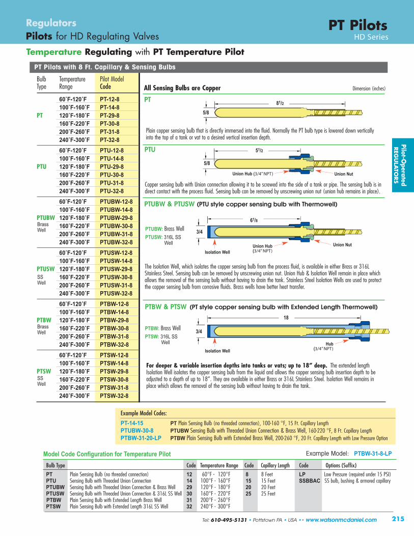
Copper sensing bulb with Union connection allowing it to be screwed into the side of a tank or pipe. The sensing bulb is indirect contact with the process fluid. Sensing bulb can be removed by unscrewing union nut (union hub remains in place).
18
215
PT PilotsRegulators Pilots for HD Regulating Valves HD Series
Temperature Regulating with PT Temperature Pilot
PT Pilots with 8 Ft. Capillary & Sensing Bulbs
Bulb Temperature Pilot ModelType Range Code
60˚F-120˚F PT-12-8100˚F-160˚F PT-14-8
PT 120˚F-180˚F PT-29-8160˚F-220˚F PT-30-8200˚F-260˚F PT-31-8240˚F-300˚F PT-32-860˚F-120˚F PTU-12-8100˚F-160˚F PTU-14-8
PTU 120˚F-180˚F PTU-29-8160˚F-220˚F PTU-30-8200˚F-260˚F PTU-31-8240˚F-300˚F PTU-32-860˚F-120˚F PTUBW-12-8100˚F-160˚F PTUBW-14-8
PTUBW 120˚F-180˚F PTUBW-29-8160˚F-220˚F PTUBW-30-8200˚F-260˚F PTUBW-31-8240˚F-300˚F PTUBW-32-860˚F-120˚F PTUSW-12-8100˚F-160˚F PTUSW-14-8
PTUSW 120˚F-180˚F PTUSW-29-8160˚F-220˚F PTUSW-30-8200˚F-260˚F PTUSW-31-8240˚F-300˚F PTUSW-32-860˚F-120˚F PTBW-12-8100˚F-160˚F PTBW-14-8
PTBW 120˚F-180˚F PTBW-29-8160˚F-220˚F PTBW-30-8200˚F-260˚F PTBW-31-8240˚F-300˚F PTBW-32-860˚F-120˚F PTSW-12-8100˚F-160˚F PTSW-14-8
PTSW 120˚F-180˚F PTSW-29-8160˚F-220˚F PTSW-30-8200˚F-260˚F PTSW-31-8240˚F-300˚F PTSW-32-8
Model Code Configuration for Temperature Pilot Example Model: PTBW-31-8-LP
Bulb Type Code Temperature Range Code Capillary Length Code Options (Suffix)
PT Plain Sensing Bulb (no threaded connection) 12 60°F - 120°F 8 8 Feet LP Low Pressure (required under 15 PSI)PTU Sensing Bulb with Threaded Union Connection 14 100°F - 160°F 15 15 Feet SSBBAC SS bulb, bushing & armored capillaryPTUBW Sensing Bulb with Threaded Union Connection & Brass Well 29 120°F - 180°F 20 20 Feet PTUSW Sensing Bulb with Threaded Union Connection & 316L SS Well 30 160°F - 220°F 25 25 FeetPTBW Plain Sensing Bulb with Extended Length Brass Well 31 200°F - 260°FPTSW Plain Sensing Bulb with Extended Length 316L SS Well 32 240°F - 300°F
Plain copper sensing bulb that is directly immersed into the fluid. Normally the PT bulb type is lowered down verticallyinto the top of a tank or vat to a desired vertical insertion depth.
PT
PTU
PTUBW & PTUSW (PTU style copper sensing bulb with Thermowell)
PTBW & PTSW (PT style copper sensing bulb with Extended Length Thermowell)
51/2
5/8
All Sensing Bulbs are Copper
Example Model Codes:
PT-14-15 PT Plain Sensing Bulb (no threaded connection), 100-160 °F, 15 Ft. Capillary LengthPTUBW-30-8 PTUBW Sensing Bulb with Threaded Union Connection & Brass Well, 160-220 °F, 8 Ft. Capillary Length PTBW-31-20-LP PTBW Plain Sensing Bulb with Extended Brass Well, 200-260 °F, 20 Ft. Capillary Length with Low Pressure Option
Union Hub (3/4” NPT)
Union Nut
For deeper & variable insertion depths into tanks or vats; up to 18” deep. The extended lengthIsolation Well isolates the copper sensing bulb from the liquid and allows the copper sensing bulb insertion depth to beadjusted to a depth of up to 18”. They are available in either Brass or 316L Stainless Steel. Isolation Well remains inplace which allows the removal of the sensing bulb without having to drain the tank.
Pilot-Operated
REG
ULA
TORS
The Isolation Well, which isolates the copper sensing bulb from the process fluid, is available in either Brass or 316LStainless Steel. Sensing bulb can be removed by unscrewing union nut. Union Hub & Isolation Well remain in place whichallows the removal of the sensing bulb without having to drain the tank. Stainless Steel Isolation Wells are used to protectthe copper sensing bulb from corrosive fluids. Brass wells have better heat tr ansfer.
Dimension (inches)
PTBW: Brass WellPTSW: 316L SS
Well
5/881/2
3/4
61/8
3/4
Union Hub(3/4” NPT)
Union Nut
Hub(3/4” NPT)
Isolation Well
Isolation Well
BrassWell
BrassWell
SSWell
SSWell
PTUBW: Brass WellPTUSW: 316L SS
Well
Tel: 610-495-5131 • Pottstown PA • USA •• www.watsonmcdaniel.com

216
Temperature Regulating with PT Temperature Pilot
PT PilotsRegulators Pilots for HD Regulating Valves HD Series
63/4”
referenceSensing
Bulbchart
Union Hub3/4” NPTthreads into side of tank or pipe
Union Nutallows for removalof sensing bulb
Controlling Temperature of a large Tank of Water using PT-Temperature Pilot
Controlling Temperature
PT-pilot is used for temperature control when steam is used onheating applications. The PT style pilot is a “solid liquid fill”design made up of a temperature probe connected by a lengthof capillary tubing to a bellows in the pilot valve. When thetemperature bulb is heated the liquid inside the probe expandsthe bellows and closes off the pilot valve. The opening andclosing of the pilot controls the flow of steam thru the mainvalve; which maintains system temperature. PT-pilot controlstemperature through a range of 60-300˚F.
An overheat protection bellows is incorporated into sensing bulb.
Controlling Temperature and Limiting Pressure using PT-Temperature Pilot & PP-Pressure Pilot
steam
HD MainValve
PTTemperature
Pilot
sensingbulb
heatexchanger
hot waterstorage tank
PressurePilotHD
MainValve
TemperaturePilot
tempprobe
heatexchanger
hotwateroutlet
coldwaterinlet
PT Pilot Dimensionscapillary
HD Main Valvewith
PT-Temperature Pilot
HD Main Valvewith
• PP-Pressure Pilot• PT-Temperature Pilot
Controlling Temperature & Limiting Pressureto a Maximum ValueThe PT & PP Pilots combination is used when it’srequired to control temperature while limitingdownstream pressure to a maximum value. When the PT & PP Pilots combination is used, thedownstream pressure is limited to a maximum settingby the pressure pilot, while the temperature pilotmaintains the correct temperature of the process.This eliminates the need for a separate pressurereducing valve.
Pilo
t-O
pera
ted
REG
ULA
TORS
steam
reduced outlet pressureinlet
pressure
armour
sensing b ulb
o ve rheatprotectionbellows
bellows
pilot valve
www.watsonmcdaniel.com •• Pottstown PA • USA • Tel: 610-495-5131

Model Code for Main Valve: HD-17-F150(2” HD Series Valve with 150# Flanges)
Model Code for Pilot: PP-B (Pressure Pilot with 20-100 PSIG Range)
Model Code for Pilot: PTU-14-8(Temperature Pilot (100-160˚ F) with 8 Ft. Capillary)
Model Code for Secondary Pilot Adapter*: BADAPTER
217
DIMENSIONS HD-Ser ies – inchesFace-To-Face Weight (lbs)
Size NPT 150# 300# B C D E F G NPT FLG1/2” 43/8 – – 51/2 91/4 61/2 61/2 141/2 101/4 18 –3/4” 43/8 – – 51/2 91/4 61/2 61/2 141/2 101/4 18 –1” 53/8 51/2 6 61/4 91/4 7 81/4 141/2 101/4 23 35
11/4” 61/2 – – 73/8 91/4 83/4 71/4 141/2 103/4 43 –11/2” 71/4 67/8 73/8 73/8 91/4 83/4 71/4 141/2 103/4 43 60
2” 71/2 81/2 9 81/4 91/4 107/8 71/2 141/2 111/4 65 8521/2” – 93/8 10 9 91/4 113/4 73/4 141/2 111/4 – 105
3” – 10 103/4 87/8 91/4 131/4 81/2 141/2 12 – 1454” – 117/8 121/2 107/8 91/4 61/2 91/2 141/2 13 – 2356” – 151/8 16 141/8 93/4 193/4 103/4 15 141/4 – 470
PT PilotsRegulators Pilots for HD Regulating Valves HD Series
Temperature Regulating with PT Temperature Pilot
E
B
C
D
MATERIALS for HD Main ValveBody Ductile IronCover Ductile IronGasket Grafoil/GarlockCover Screws SteelPilot Adapter Ductile Iron/Cast SteelScreen Stainless SteelTubing CopperValve Seat Hardened SST (55 Rc)Valve Disc Hardened SST (55 Rc)Diaphragm Phosphor Bronze
MATERIALS for PT Temperature PilotPilot Body Ductile IronBellows Phosphor BronzeHead & Seat Assembly Hardened SST (55 Rc)
MATERIALS for PP Pressure PilotPilot Body & Cover Ductile Iron or Cast SteelHead & Seat Gasket 302 SSDiaphragm Phosphor BronzeHead & Seat Assembly Hardened SST (55 Rc)
G
B
F
D
HD Main ValvewithPT-Temperature Pilot
Model Code for Main Valve: HD-17-F150(2” HD Series Valve with 150# Flanges)
Model Code for Pilot: PTU-14-8(Temperature Pilot (100-160˚ F) with 8 Ft. Capillary)
* If 2 Pilots are used on the same valve, a SecondaryPilot Adapter is required.
HD Main Valvewith• PP-Pressure Pilot• PT-Temperature Pilot
Pilot-Operated
REG
ULA
TORS
Pressure ModelRanges
3-25 PSIG PP-Y20-100 PSIG PP-B80-200 PSIG PP-R
For Pressure Pilot
HD ValvewithTemperaturePilot
HD ValvewithTemperature&Pressure Pilot
Tel: 610-495-5131 • Pottstown PA • USA •• www.watsonmcdaniel.com
218
Pressure Control with PA Air-Loaded Pilot
PA Series PilotsRegulators Pilots for HD Regulating Valves HD Series
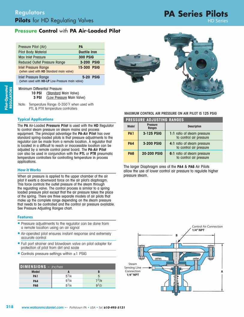
Typical Applications
The PA Air-Loaded Pressure Pilot is used with the HD Regulatorto control steam pressure on steam mains and processequipment. The principal advantage the PA-Air Pilot has overstandard spring-loaded pilots is that pressure adjustments to theregulator can be made from a remote location. A regulator that is located in a difficult to reach or inaccessible location can beadjusted by a remote control panel board. The PA-Air Pilotcan also be used in conjunction with the PTL or PTR pneumatictemperature controllers for controlling temperature in processapplications.
How it Works
When air pressure is applied to the upper chamber of the air pilot it exerts a downward force on the air pilot’s diaphragm. This force controls the outlet pressure of the steam through the regulating valve. The control process is similar to a springloaded pressure pilot except that the air pressure takes the placeof the spring. There are three separate models of air pilots thatmake up the complete range depending on the steam pressurethat needs to be controlled and the control air pressure available.See Pressure Adjusting Ranges chart.
Features
• Pressure adjustments to the regulator can be done froma remote location using an air signal
• Air-operated pilot ensures instant response and extremelyaccurate control
• Full port strainer and blowdown valve on pilot adapter forprotection of pilot from dirt and scale
• Controls pressure settings within ±1 PSIG
PRESSURE ADJUSTING RANGES
Model Pressure DescriptionRanges
PA1 3-125 PSIG 1:1 ratio of steam pressure to control air pressure
PA4 3-200 PSIG 4:1 ratio of steam pressure to control air pressure
PA6 20-200 PSIG 6:1 ratio of steam pressure to control air pressure
DIMENSIONS – inchesModel A BPA1 51/4 5
PA4 51/4 77/8PA6 51/4 91/2
B
A
Steam Sensing LineConnection
1/4” NPT
Control Air Connection1/4” NPT
The larger Diaphragm area of the PA4 & PA6 Air Pilots allow the use of lower control air pressure to regulate higherpressure steam.
MAXIMUM CONTROL AIR PRESSURE ON AIR PILOT IS 125 PSIG
Note: Temperature Range: 0-350 ˚F when used with PTL & PTR temperature controllers
Pressure Pilot (Air) PA Pilot Body Material Ductile IronMax Inlet Pressure 300 PSIGReduced Outlet Pressure Range 3-200 PSIGInlet Pressure Range 15-300 PSIG(when used with HD Standard main valve)
Inlet Pressure Range 5-20 PSIG(when used with HD-LP Low-Pressure main valve)
Pilo
t-O
pera
ted
REG
ULA
TORS
www.watsonmcdaniel.com •• Pottstown PA • USA • Tel: 610-495-5131
Minimum Differential Pressure:10 PSI (Standard Main Valve)3 PSI (Low Pressure Main Valve)
219
PA Series PilotsRegulators Pilots for HD Regulating Valves HD Series
Pressure Control with PA Air-Loaded Pressure Pilot
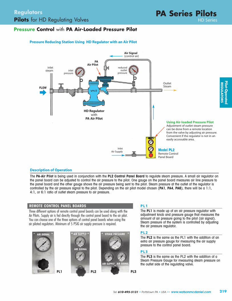
REMOTE CONTROL PANEL BOARDSThree different options of remote control panel boards can be used along with the Air Pilots. Supply air is fed directly through the control panel board to the air pilot. You can choose one of the three options of control panel boards when using the air piloted regulators. Minimum of 5 PSIG air supply pressure is required.
P L 1The PL1 is made up of an air pressure regulator withadjustment knob and pressure gauge that measures theamount of air pressure going to the pilot (air signal).Steam pressure of the system is controlled by adjustingthe air pressure regulator.
P L 2The PL2 is the same as the PL1 with the addition of anextra air pressure gauge for measuring the air supplypressure to the control panel board.
P L 3The PL3 is the same as the PL2 with the addition of aSteam Pressure Gauge for measuring steam pressure onthe outlet side of the regulating valve.
InletAir Supply
OutletSteam
Air Signal(control air)
inletsteam
PL1 PL3PL2
AIR SIGNAL AIR SUPPLY
AIR SIGNAL
AIR SUPPLY
STEAM PRESSURE
AIR SIGNAL
FLOW
HD Regulatorwith
PA Air Pilot
Pressure Reducing Station Using HD Regulator with an Air Pilot
PAAir Pilot
Description of Operation
The PA-Air Pilot is being used in conjunction with the PL2 Control Panel Board to regulate steam pressure. A small air regulator onthe panel board can be adjusted to control the air pressure to the pilot. One gauge on the panel board measures air line pressure tothe panel board and the other gauge shows the air pressure being sent to the pilot. Steam pressure at the outlet of the regulator iscontrolled by the air pressure signal to the pilot. Depending on the air pilot model chosen (PA1, PA4, PA6), there will be a 1:1,4:1, or 6:1 ratio of outlet steam pressure to air pressure.
Using Air-loaded Pressure PilotAdjustment of outlet steam pressurecan be done from a remote locationfrom the valve by adjusting air pressure.Convenient if the r e gula tor is no t in an ea sily a ccessa ble area.
Model PL2 Remote Control Panel Board
reducedoutlet
pressureinlet
pressure
Pilot-Operated
REG
ULA
TORS
Tel: 610-495-5131 • Pottstown PA • USA •• www.watsonmcdaniel.com

220
Pressure Control with PA Air-Loaded Pilot
PA Series PilotsRegulators Pilots for HD Regulating Valves HD Series
Pilo
t-O
pera
ted
REG
ULA
TORS
Upper & LowerPilot Diaphragms
Downstream PressureSensing Line
HighPresssure
Diaphragm
SteamPressureOpensMain Valve
BleedOrifice
MainValve
Closed
MainValveOpen
Pilot ValveOpen
Pilot ValveClosed
LowPressure
HighPresssure
LowPressure
High-Pressure steam pushes updiaphragm & opens valve
How it WorksWhen air pressure is applied to the upper chamber of the air pilot, it exerts a downward force on the air pilot’s diaphragm. The lower chamber of the air pilot is connected to the outlet side of the regulator using a sensing line. The purpose of the sensingline is to sense the pressure on the outlet side of the regulator and direct it under the lower pilot diaphragm to push it upwards.When the intended set pressure is reached, the pilot valve closes, which then closes off the flow path of steam to the underside of the diaphragm chamber in the regulator body. The regulator modulates open and closed maintaining the desired downstreampressure. To change downstream pressure, increase or decrease air pressure to pilot accordingly.
Air Pressure pushesdown on Upper PilotDiaphragm
Air Pressure determinesoutlet steam pressure
Steam Pressure pushesupward on Lower PilotDiaphragm
When pilot valve closes, steampressure in lower diaphragmchamber bleeds off allowingmain valve to close
When pilot valve opens,high pressure steam entersdiaphragm chamber
PRESSURE ADJUSTING RANGES
Model Pressure DescriptionRanges
PA1 3-125 PSIG 1:1 ratio of steam pressure to control air pressure
PA4 3-200 PSIG 4:1 ratio of steam pressure to control air pressure
PA6 20-200 PSIG 6:1 ratio of steam pressure to control air pressure
The larger Diaphragm area of the PA4 & PA6 Air Pilots allow the use of lower control air pressure to regulate higherpressure steam.
MAXIMUM CONTROL AIR PRESSURE ON AIR PILOT IS 125 PSIG
If outlet steam pressurefalls below set point, pilotvalve opens.
www.watsonmcdaniel.com •• Pottstown PA • USA • Tel: 610-495-5131
221
PA Series PilotsRegulators Pilots for HD Regulating Valves HD Series
Pressure Control with PA Air-Loaded Pilot
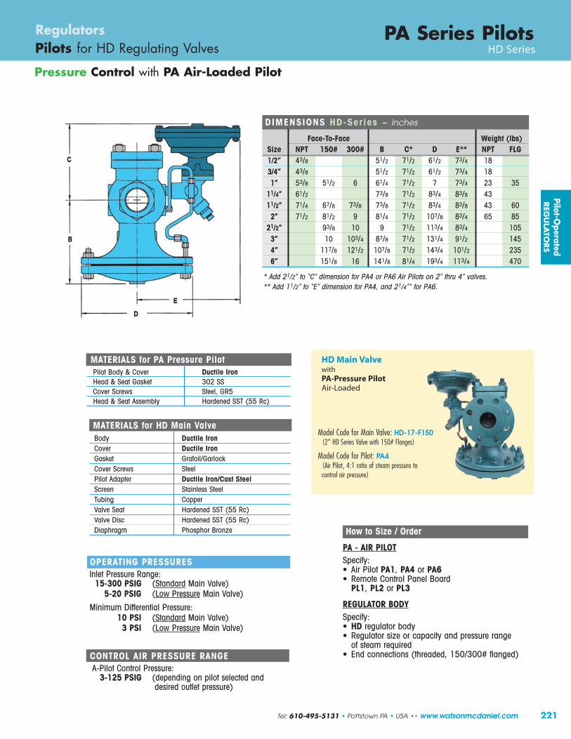
DIMENSIONS HD-Ser ies – inches
Face-To-Face Weight (lbs)Size NPT 150# 300# B C* D E** NPT FLG1/2” 43/8 51/2 71/2 61/2 73/4 183/4” 43/8 51/2 71/2 61/2 73/4 181” 53/8 51/2 6 61/4 71/2 7 73/4 23 35
11/4” 61/2 73/8 71/2 83/4 83/8 4311/2” 71/4 67/8 73/8 73/8 71/2 83/4 83/8 43 60
2” 71/2 81/2 9 81/4 71/2 107/8 83/4 65 8521/2” 93/8 10 9 71/2 113/4 83/4 105
3” 10 103/4 87/8 71/2 131/4 91/2 1454” 117/8 121/2 107/8 71/2 143/4 101/2 2356” 151/8 16 141/8 81/4 193/4 113/4 470
* Add 21/2” to “C” dimension for PA4 or PA6 Air Pilots on 2” thru 4” valves.** Add 11/2” to “E” dimension for PA4, and 21/4”” for PA6.
E
B
C
D
How to Size / Order
PA - AIR PILOTSpecify:• Air Pilot PA1, PA4 or PA6• Remote Control Panel Board
PL1, PL2 or PL3
REGULATOR BODYSpecify:• HD regulator body• Regulator size or capacity and pressure range
of steam required• End connections (threaded, 150/300# flanged)
OPERATING PRESSURESInlet Pressure Range:
15-300 PSIG (Standard Main Valve)5-20 PSIG (Low Pressure Main Valve)
Minimum Differential Pressure:10 PSI (Standard Main Valve)
3 PSI (Low Pressure Main Valve)
CONTROL AIR PRESSURE RANGEA-Pilot Control Pressure:
3-125 PSIG (depending on pilot selected and desired outlet pressure)
Model Code for Main Valve: HD-17-F150(2” HD Series Valve with 150# Flanges)
Model Code for Pilot: PA4 (Air Pilot, 4:1 ratio of steam pressure to control air pressure)
HD Main ValvewithPA-Pressure PilotAir-Loaded
MATERIALS for HD Main ValveBody Ductile IronCover Ductile IronGasket Grafoil/GarlockCover Screws SteelPilot Adapter Ductile Iron/Cast SteelScreen Stainless SteelTubing CopperValve Seat Hardened SST (55 Rc)Valve Disc Hardened SST (55 Rc)Diaphragm Phosphor Bronze
MATERIALS for PA Pressure PilotPilot Body & Cover Ductile IronHead & Seat Gasket 302 SSCover Screws Steel, GR5Head & Seat Assembly Hardened SST (55 Rc)
Pilot-Operated
REG
ULA
TORS
Tel: 610-495-5131 • Pottstown PA • USA •• www.watsonmcdaniel.com

222
On/Off Control using an Electric Solenoid
Typical Applications
Typically used for automatic operation, remote control,programmed cycling, sequential function interlocks with otherequipment, and emergency shut-off in case of power failure.
How it Works
The PS-Solenoid Pilot can be used in conjunction with Pressure,Temperature, or Air Pilots to electrically control on/off operation ofthe HD Regulator. When the solenoid pilot is used, the regulatorcan be turned on or off by electrically activating or de-activatingthe solenoid.Normally Closed (NC) – StandardThe normally CLOSED Solenoid Pilot remains closed in the non-activated state. The regulating valve will remain closed until an electrical signal is sent to the solenoid pilot. The signalis required to allow the regulator to operate. This is known as a fail-safe condition.Normally Open (NO) – OptionalThe normally OPENED Solenoid Pilot remains open in the non-activated state. The regulating valve will function normallyunless an electrical signal is used to shut off the solenoid pilot.
Features
• Available normally opened (NO) or normally closed (NC)• Full-port strainer and blow-down valve on pilot adapter to
eliminate failure caused by contaminated steam systems
Options
• Normally open solenoid• NEMA Ratings: NEMA 4 and NEMA 7• Voltage: 24 VAC, 120 VAC, 240 VAC
• Max Inlet Pressure: 250 PSIG
Standard Solenoid Pilots AvailableSteam Inlet Pressure 0-180 PSIG
180-250 PSIG
NEMA Ratings NEMA 4 – Waterproof (standard)NEMA 7 – Explosion-proof (optional)
Voltage 24 Volts AC110-120 Volts AC 220-240 Volts AC
Control Action Normally Closed (standard)Normally Open (special ordered)
Solenoid PilotRegulators Pilots for HD Regulating Valves HD Series
Model PMO WeightCode PSIG lbs
PS1 15-180 4.5
PS2 180-250 5.5
PS1-LP 0-20 4.5
Use PS1-LP for Low Pressure applications under 15 PSI.Model Code Configuration ChartModels Pressure PSI Code Voltage Code Action Code Rating
PS1 15-180 PSIG 24 24 VAC NC Normally Closed (Standard) N4 Standard. Meets enclosure Type 4 (water proof).PS2 180-250 PSIG 120 110 -120 VAC NO Normally Open (special ordered) N7 Meets NEMA 4 & 7 Rating (water proof & explosion proof)PS1-LP 0-20 PSIG 240 220 - 240 VAC
Example Model Codes:
1) PS1-120-NC-N4 NEMA 4 (standard)2) PS1-120-NC-N7 NEMA 4 & 7 (waterproof & explosion proof)
Pilo
t-O
pera
ted
REG
ULA
TORS
www.watsonmcdaniel.com •• Pottstown PA • USA • Tel: 610-495-5131
Solenoid Pilot (Electric) PS1 & PS2 Pilot Body Material Cast IronValve Head & Seat Stainless SteelMax Inlet Pressure 250 PSIGPressure RangePS1 0-180 PSIGPS2 180-250 PSIG

E
B
C
D
223
MATERIALS for On/Off Solenoid PilotPilot Body & Cover Ductile IronSeat Gasket 302 SSCover Screws Steel, GR5Internals Stainless Steel
OPERATING PRESSURESInlet Pressure Range:
15 PSIG (Standard Main Valve)5 PSIG (Low Pressure Main Valve)
Minimum Differential Pressure:10 PSI (Standard Main Valve)
3 PSI (Low Pressure Main Valve)
Solenoid PilotRegulators Pilots for HD Regulating Valves HD Series
DIMENSIONS HD-Ser ies – inches
Face-To-Face Weight (lbs)Size NPT 150# 300# B C* D E** NPT FLG1/2” 43/8 51/2 71/2 61/2 73/4 183/4” 43/8 51/2 71/2 61/2 73/4 181” 53/8 51/2 6 61/4 71/2 7 73/4 23 35
11/4” 61/2 73/8 71/2 83/4 83/8 4311/2” 71/4 67/8 73/8 73/8 71/2 83/4 83/8 43 60
2” 71/2 81/2 9 81/4 71/2 107/8 83/4 65 8521/2” 93/8 10 9 71/2 113/4 83/4 105
3” 10 103/4 87/8 71/2 131/4 91/2 1454” 117/8 121/2 107/8 71/2 143/4 101/2 2356” 151/8 16 141/8 81/4 193/4 113/4 470
MATERIALS for HD Main ValveBody Ductile IronCover Ductile IronGasket Grafoil/GarlockCover Screws SteelPilot Adapter Ductile Iron/Cast SteelScreen Stainless SteelTubing CopperValve Seat Hardened SST (55 Rc)Valve Disc Hardened SST (55 Rc)Diaphragm Phosphor Bronze
HD Main ValvewithPS1 On/Off ControlSolenoid Pilot
HD Main Valvewith• PT-Temperature Pilot• PS1 On/Off Control
Solenoid Pilot
HD Main Valvewith• PP-Pressure Pilot• PT-Temperature Pilot• PS1 On/Off Control
Solenoid Pilot
Pilot-Operated
REG
ULA
TORS
Tel: 610-495-5131 • Pottstown PA • USA •• www.watsonmcdaniel.com
224
Pneumatic Temperature Controllers (must be used with PA-Air Pilot)
PTL & PTR SeriesRegulators Controllers for HD Regulating Valves HD Series
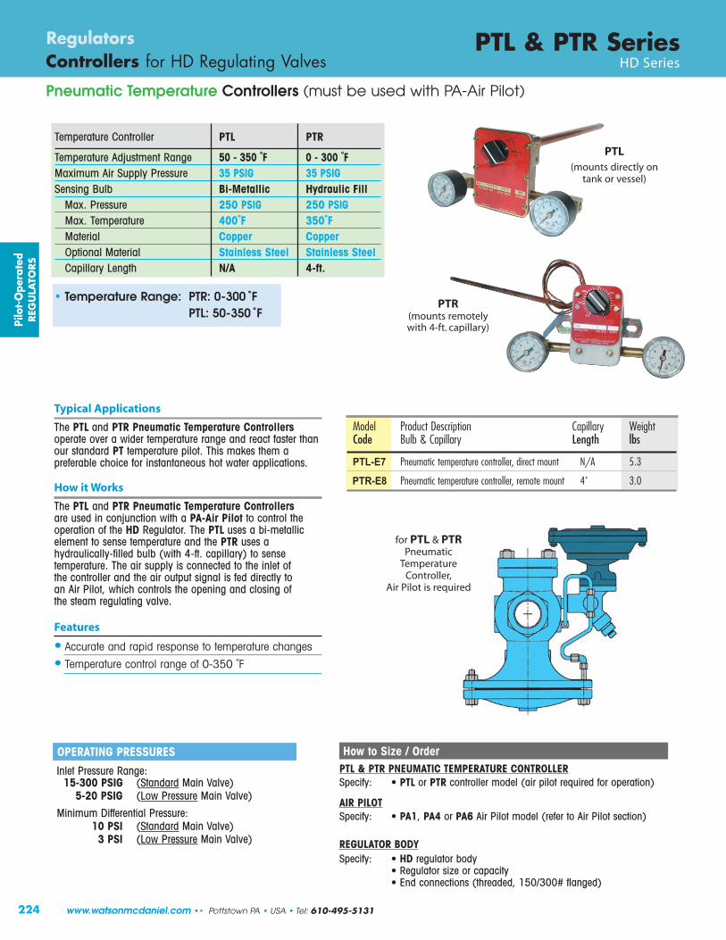
Temperature Controller PTL PTR
Temperature Adjustment Range 50 - 350 ˚F 0 - 300 ˚FMaximum Air Supply Pressure 35 PSIG 35 PSIGSensing Bulb Bi-Metallic Hydraulic Fill
Max. Pressure 250 PSIG 250 PSIGMax. Temperature 400˚F 350˚FMaterial Copper CopperOptional Material Stainless Steel Stainless SteelCapillary Length N/A 4-ft.
PTL(mounts directly on
tank or vessel)
PTR(mounts remotelywith 4-ft. capillary)
Typical Applications
The PTL and PTR Pneumatic Temperature Controllersoperate over a wider temperature range and react faster thanour standard PT temperature pilot. This makes them apreferable choice for instantaneous hot water applications.
How it Works
The PTL and PTR Pneumatic Temperature Controllersare used in conjunction with a PA-Air Pilot to control theoperation of the HD Regulator. The PTL uses a bi-metallicelement to sense temperature and the PTR uses ahydraulically-filled bulb (with 4-ft. capillary) to sensetemperature. The air supply is connected to the inlet of the controller and the air output signal is fed directly to an Air Pilot, which controls the opening and closing of the steam regulating valve.
Features
• Accurate and rapid response to temperature changes
• Temperature control range of 0-350 ˚F
How to Size / OrderPTL & PTR PNEUMATIC TEMPERATURE CONTROLLERSpecify: • PTL or PTR controller model (air pilot required for operation)
AIR PILOTSpecify: • PA1, PA4 or PA6 Air Pilot model (refer to Air Pilot section)
REGULATOR BODYSpecify: • HD regulator body
• Regulator size or capacity• End connections (threaded, 150/300# flanged)
• Temperature Range: PTR: 0-300 ˚FPTL: 50-350 ˚F
OPERATING PRESSURES
Inlet Pressure Range:15-300 PSIG (Standard Main Valve)
5-20 PSIG (Low Pressure Main Valve)
Minimum Differential Pressure:10 PSI (Standard Main Valve)
3 PSI (Low Pressure Main Valve)
Model Product Description Capillary WeightCode Bulb & Capillary Length lbs
PTL-E7 Pneumatic temperature controller, direct mount N/A 5.3
PTR-E8 Pneumatic temperature controller, remote mount 4’ 3.0
for PTL & PTRPneumatic
TemperatureController,
Air Pilot is required
Pilo
t-O
pera
ted
REG
ULA
TORS
www.watsonmcdaniel.com •• Pottstown PA • USA • Tel: 610-495-5131
225
PTL & PTR Series Regulators Controllers for HD Regulating Valves HD Series
Pneumatic Temperature Controllers (must be used with PA-Air Pilot)
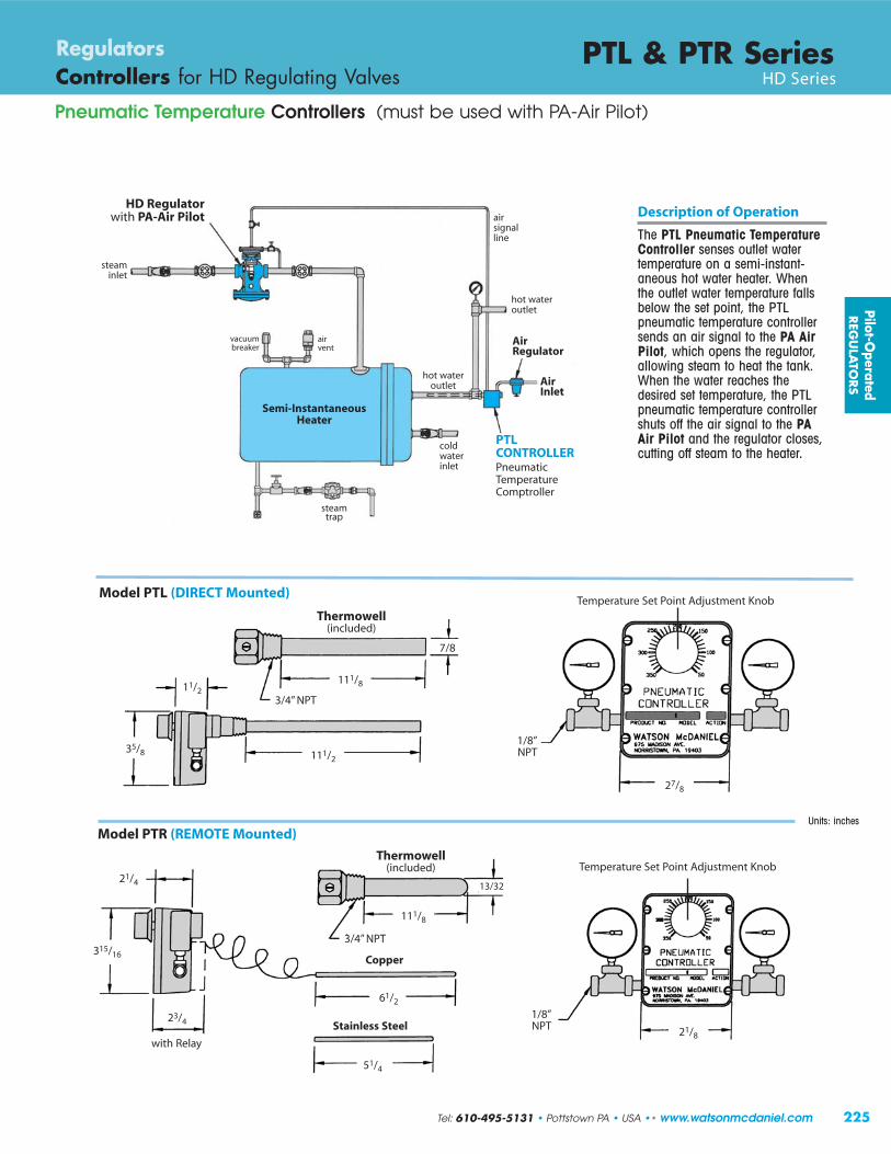
Model PTL (DIRECT Mounted)
Model PTR (REMOTE Mounted)
Description of Operation
The PTL Pneumatic TemperatureController senses outlet watertemperature on a semi-instant-aneous hot water heater. Whenthe outlet water temperature fallsbelow the set point, the PTLpneumatic temperature controllersends an air signal to the PA AirPilot, which opens the regulator,allowing steam to heat the tank.When the water reaches thedesired set temperature, the PTLpneumatic temperature controllershuts off the air signal to the PAAir Pilot and the regulator closes,cutting off steam to the heater.
HD Regulator with PA-Air Pilot
steaminlet
Semi-InstantaneousHeater
coldwaterinlet
PTLCONTROLLERPneumaticTemperatureComptroller
Air Regulator
hot wateroutlet
air signalline
Thermowell(included)
111/8
3/4” NPT
7/8
111/2
11/2
35/8
21/4
315/16
23/4
with Relay
3/4” NPT
61/2
Stainless Steel
51/4
1/8”NPT 21/8
13/32
Copper
27/8
1/8”NPT
111/8
Temperature Set Point Adjustment Knob
Units: inches
vacuumbreaker
Air Inlet
steamtrap
air vent
Temperature Set Point Adjustment Knob
hot wateroutlet
Pilot-Operated
REG
ULA
TORS
Tel: 610-495-5131 • Pottstown PA • USA •• www.watsonmcdaniel.com
Thermowell(included)

226
Temperature Control with PTRP Temperature Pilot
PTRP Series PilotsRegulators Pilots for HD Regulating Valves HD Series
Typical Applications
The PTRP-Temperature Pilot is used with the HD Regulator to control temperature in various processes and systems. The PTRPuses a vapor tension system to actuate the bellows in the temper turepilot giving it a faste r reaction time and better temperature sensitivitythan the standard PT pilot. They can be used on: oil heaters, ovens,process heaters, vats, dryers, jacketed kettles, and semi-Instantaneouswater h eaters.
Features
• Stainless steel valve and seat• Standard bulb & capillary is copper, which has the best heat
tran sfer prope r ties . • Standard c apillary length is 8 ft. with 316 stainless steel
armour- protection
Options
• Capillary Lengths: Available in 8, 12, 16, 20 & 24-ft.• Special Materials: Sensing bulb, thermowells, and capillary are
available in special corrosion resistant materials.- 316 stainless steel capillary, bulb & bushing- 316 stainless steel armor with standard capillary
• Thermowell (Separable Socket): Available in stainless steel or copper• Temperature Sensing Dial: Indicates temperature of process
being controlled• SDWA Compliance (Safe Drinking Water Act); Consult factory
Model PTRP-94 contains
TemperatureIndicating Dial
Model PTRP-91
is Non-Indicating
TemperatureAdjustment Screw
Teflon V-RingPacking
Seat
Specifications
Dial Thermometer: 4" dial, stainless steel case, swivel and angle adjustment (Model PTRP-94 only)
Housing: Die cast aluminum, epoxy powder coated grey finish
Bellows: High pressure brass, corrosion resistant, tin plated finish (not shown)
Over-Temperature Upper range limit +100° F Protection:
Model PTRPPilot Body Material Cast SteelMax Inlet Pressure 300 PSIGTemperature Control Range 20-440˚ FSteam Inlet Pressure Range 15-300 PSIG(when Standard Temperature Pilotis used with HD Standard main valve)
Steam Inlet Pressure Range 5-20 PSIG(when Low-Pressure Temperature Pilotis used with HD-LP Low-Pressure main valve)
11.6”
Over-TemperatureProtectionSpring
Pilo
t-O
pera
ted
REG
ULA
TORS
www.watsonmcdaniel.com •• Pottstown PA • USA • Tel: 610-495-5131
LOW PRESSURE PTRP-LP Pilot (pressures under 15 PSIG)Use Code LP: Low pressure Temperature Pilot is required
for steam pressure under 15 PSI. (Range 5 - 20)
PILOT: Example Model Code: PTRP-LP-06-08-S15
LOW PRESSURE HD Main Valve (pressures under 15 PSIG)Use Code LP: A Low Pressure Main Valve must be used in conjuction with a
Low Pressure Temperature Pilot for steam pressure under 15 PSIG
MAIN VALVE: Example Model Code: HD-13-N-LP (Range 5 - 20)
(Bellows not shown)

227
PTRP Series Pilots Regulators Pilots for HD Regulating Valves HD Series
DIMENSIONS HD-Series – inches
Face-To-Face Weight (lbs)
Size NPT 150# 300# B C D E NPT FLG1/2” 43/8 51/2 14 61/2 73/4 183/4” 43/8 51/2 14 61/2 73/4 181” 53/8 51/2 6 61/4 14 7 73/4 23 35
11/4” 61/2 73/8 14 83/4 81/4 4311/2” 71/4 67/8 73/8 73/8 14 83/4 81/4 43 60
2” 71/2 81/2 9 81/4 14 107/8 81/2 65 8521/2” 93/8 10 9 14 113/4 81/2 105
3” 10 103/4 87/8 14 131/4 91/2 1454” 117/8 121/2 107/8 14 143/4 101/2 2356” 151/8 16 141/8 141/2 193/4 113/4 470
HD Valve with PTRP-Temperature Pilot ApplicationA semi-instantaneous steam-to-water heater is a common application where the simplebenefits of a self-contained, pilot-operatedregulator with temperature sensing pilot maybe favored over more complex and expensivecontrol valves. The thermally sensitive bulb ofthe PTRP pilot contains a fluid that creates avapor which increases or decreases in pressureas the sensing bulb – sensing the heated water– temperature increases or decreases. Thisvapor pressure is transmitted hydraulically tothe bellows, which actuates the pilot and HDregulator to control the flow of steam into theheater. At start-up, the pilot is manually-adjusted to raise the temperature set point and allow steam to flow through the pilot and valve. As the heated water nears thetemperature set point, the vapor pressure in the sensing bulb increases and expands thebellows, closing the pilot and regulator toproportionally limit the steam supply.
MATERIALS for PTRP PilotPilot Body Cast SteelValve and Seat Stainless steel
Support Bracket AluminumBulb & Capillary Copper
(optional stainless steel)All Other Parts Brass
E
B
C
D
4.0”
Steam Trap
3” NPTCold waterinlet
1/2” NPTSolenoid-operateddischarge valve(pipe to drain)
2” NPTHot water
outlet
condensate return
MATERIALS for HD Main ValveBody Ductile IronCover Ductile IronGasket Grafoil/GarlockCover Screws SteelPilot Adapter Ductile Iron/Cast SteelScreen Stainless SteelTubing CopperValve Seat Hardened SST (55 Rc)Valve Disc Hardened SST (55 Rc)Diaphragm Phosphor Bronze
Pilot-Operated
REG
ULA
TORS
PTRPTemperature
Pilot
Steam
Tel: 610-495-5131 • Pottstown PA • USA •• www.watsonmcdaniel.com

228
Temperature Control
PTRP Series PilotsRegulators Pilots for HD Regulating Valves HD Series
Thermowell Option (ordered separately)Thermowells isolate and protect the sensing bulb from the process fluid; available in either brass (better heat transferproperties) or Stainless Steel for corrosion resistance. They allow for sensing bulb removal and replacement withouthaving to drain liquid from the system. For corrosive applications, a Stainless Steel thermowell (with a copper sensingbulb) can be used. For best temperature control use a copper sensing bulb with a brass thermowell. Thermowells arealso recommended for applications with excessive system pressures or extremely turbulent flow to protect the sensingbulb from damage.
Sensing Bulb Selection & Installation: The sensing bulb and capillary is available in either Copper (standard) or Stainless Steel (for corrosive applications). Copper has the best heattransfer properties and should always be chosen unless used in corrosive service. Sensing bulb length is dependent upon the capillary lengthrequired; longer capillary lengths require a longer bulb to hold the additional actuating fluid. When installing the sensing bulb, the Union Hub is first threaded into a tank or piping system. The bulb slides thru the Union Hub and held in place by threading in the Union Nut. The angledseating surface of the bulb forms a metal-to-metal seal to the Union Hub, preventing the leakage of process fluid.
STAINLESS STEEL ARMOR PROTECTED CAPILLARY
“U” Sensing Bulb Length
UNION NUTUnscrews to allow
for Sensing Bulb Removal
UNION HUB - 1“ NPT Threaded into side of vessel & is not permanently fastened to bulb.
Sensing Bulb
“A” Insertion Length
“D”
Tank Wall
HUB - 11/4“ NPT (Attached to thermowell and threaded into side of vessel)
Sensi ngThermowellremains in place
Sensing Bulb
Bulb beingremoved fromside of tank
THERMOWELL LENGTH
Sensing Bulb & Capillary
ORDER Sensing Bulb Capillary Tubing Capillary Length in Feet “D”CODE Material Material 8, 12, 16 20 24 Bulb Dia.
S15 Copper Copper with A 13” 16” 20”1”(Brass Union Hub) Stainless Steel
U 12.25” 15.25” 19.25”Spiral Armor
S16 Stainless Steel Stainless Steel A 13” 16” 20”1”(Stainless Steel Union Hub) with Stainless Steel
U 12.25” 15.25” 19.25”Spiral Armor
SB15* Copper Copper with A 9” 9” 9”3/4”(special 9”) (Brass Union Hub) Stainless Steel
U 8.25” 8.25” 8.25”(9” bulb) Spiral Armor
SB16* Stainless Steel Stainless Steel A 9” 9” 9”`3/4”(special 9”) (Stainless Steel Union Hub) with Stainless Steel
U 8.25” 8.25” 8.25”(9” bulb) Spiral Armor
3/4“ NPT For special 9” Bulb.
1“ NPT For special 9” Bulb.
*Note for 9” Bulb:Care should be taken when using9” bulbs, and they should only beused in applications where spaceconsiderations exist. They shouldnot be used when the temperatureof the actuator housing is higherthan the sensing bulb temperature,as this condition may create erratic temperature control. Thetemperature of the actuatorhousing is affected by thesurrounding ambient temperatureas well as the steam temperatureflowing through the valve and mayreach 140˚F.
Notes: 1) Other connections and lengths may be available, consult factory.2) External pressure rating on Brass is 500 PSI max.3) External pressure rating on 316 SS is 1000 PSI max.
Brass Stainless Steel Nominal “A” INSERTION LENGTH (in.) Capillary LengthModel No. Model No. Length BULB THERMOWELL in Feet
536-S2 536-S6 13" 12.25 13.00 8, 12 or 16536-SE2 536-SE6 16" 15.25 16.00 20536-WE2 536-WE6 20" 19.25 20.00 24535-M2* 535-M6* 9" 8.25 9.00 8, 12 or 16
THERMOWELLS - Model Numbers & Lengths
Note: to ensure minimum responsetime, Heat TransferPaste should be appliedto the sensing bulbbefore installation intothe thermowell.
Pilo
t-O
pera
ted
REG
ULA
TORS
(Included with Bulb; discard when using Thermowell)
“A” Insertion Length
www.watsonmcdaniel.com •• Pottstown PA • USA • Tel: 610-495-5131

229
PTRP Series Pilots Regulators Pilots for HD Regulating Valves HD Series
Model Code Chart with Temperature Ranges (8 ft. Capillary Lengths)
Range Nominal Recommended Model Code Model Code WeightCode Range (˚F) Working Span (˚F) NON-Indicating Indicating lbs01 20 - 70 40 to 65 °F PTRP-91-01-08 PTRP-94-01-08 802* 40 - 90 65 to 85 °F PTRP-91-02-08 PTRP-94-03-08 803 30 - 115 85 to 110 °F PTRP-91-03-08 PTRP-94-03-08 804 50 - 140 110 to 135 °F PTRP-91-04-08 PTRP-94-04-08 805 75 - 165 135 to 160 °F PTRP-91-05-08 PTRP-94-05-08 806 105 - 195 160 to 190 °F PTRP-91-06-08 PTRP-94-06-08 807 125- 215 190 to 210 °F PTRP-91-07-08 PTRP-94-07-08 809 155- 250 210 to 245 °F PTRP-91-09-08 PTRP-94-09-08 810 200 - 280 245 to 275 °F PTRP-91-10-08 PTRP-94-10-08 811 225 - 315 275 to 310 °F PTRP-91-11-08 PTRP-94-11-08 812 255 - 370 305 to 365 °F PTRP-91-12-08 PTRP-94-12-08 813 295 - 420 365 to 415 °F PTRP-91-13-08 PTRP-94-13-08 814 310 - 440 415 to 435 °F PTRP-91-14-08 PTRP-94-14-08 8
* The recommended working span typically falls within the upper third of the nominal temperature range.
Model Code Configuration ChartModels Temperature Range Capillary Length Bulb
PTRP-91 Non-Indicating 01 – 14 Refer to 08 8 Feet (std) S15 (copper bulb)PTRP-94 Indicating Dial Temperature 12 12 Feet (standard)
PTRP-LP-91 Non-Indicating Range Chart 16 16 Feet S16 (SS bulb)
PTRP-LP-94 Indicating Dial 20 20 Feet SB15 (9” copper bulb)
24 24 Feet SB16 (9” SS bulb)
Note: Thermowells are ordered separately. LP = Low Pressure Models.
Explanation of PTRP-91 06 08 S15Model Number: Model Temp. Cap. Bulb
Range Length Type
Model Number: PTRP-91-06-08-S15
How to write proper model number:
CROSS REFERENCE: PTRP = Spence T-14
HD Main ValvewithPTRPTemperature Pilot
Example Model Codes:
1) PTRP-91-06-08-S15 (105°F - 195°F Temp Range, 8 ft. Capillary, 12“ Copper Bulb)2) PTRP-94-06-08-S15 (105°F - 195°F Temp Range, with Dial Thermometer, 8 ft. Capillary, 12” Copper Bulb)
Model Code for Main Valve:HD-17-F150
(2” HD Series Valve with 150# Flanged)
Model Code for Pilot: PTRP-94-06-08-S15(Temperature Pilot with Indicating Dial(105-195˚F) with 8 Ft. Capillary, Copper Bulb)
Pilot-Operated
REG
ULA
TORS
Model PTRP-94 contains Temperature Indicating DialModel PTRP-91 is Non-Indicating
Tel: 610-495-5131 • Pottstown PA • USA •• www.watsonmcdaniel.com
230
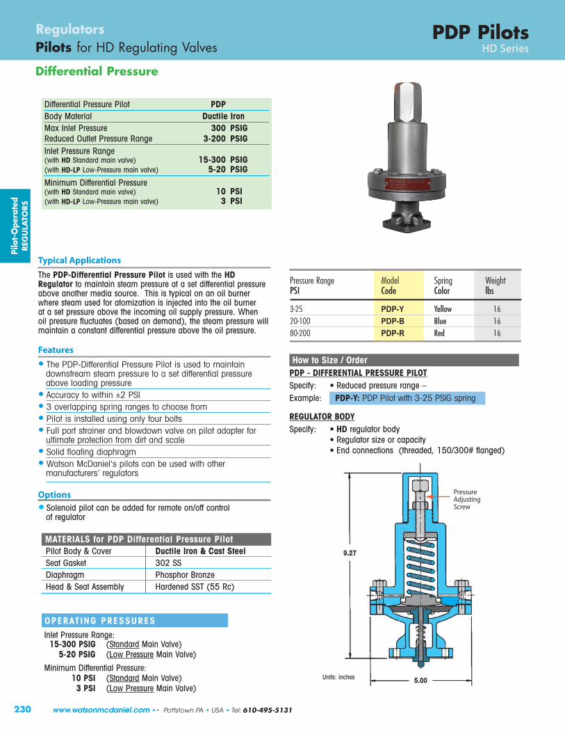
Differential Pressure
PDP PilotsRegulators Pilots for HD Regulating Valves HD Series
MATERIALS for PDP Differential Pressure PilotPilot Body & Cover Ductile Iron & Cast SteelSeat Gasket 302 SSDiaphragm Phosphor BronzeHead & Seat Assembly Hardened SST (55 Rc)
Typical Applications
The PDP-Differential Pressure Pilot is used with the HDRegulator to maintain steam pressure at a set differential pressureabove another media source. This is typical on an oil burnerwhere steam used for atomization is injected into the oil burner at a set pressure above the incoming oil supply pressure. When oil pressure fluctuates (based on demand), the steam pressure willmaintain a constant differential pressure above the oil pressure.
Features
• The PDP-Differential Pressure Pilot is used to maintain downstream steam pressure to a set differential pressureabove loading pressure
• Accuracy to within ±2 PSI• 3 overlapping spring ranges to choose from• Pilot is installed using only four bolts• Full port strainer and blowdown valve on pilot adapter for
ultimate protection from dirt and scale• Solid floating diaphragm• Watson McDaniel's pilots can be used with other
manufacturers’ regulators
Options
• Solenoid pilot can be added for remote on/off controlof regulator
How to Size / OrderPDP - DIFFERENTIAL PRESSURE PILOTSpecify: • Reduced pressure range – Example: PDP-Y: PDP Pilot with 3-25 PSIG spring
REGULATOR BODYSpecify: • HD regulator body
• Regulator size or capacity• End connections (threaded, 150/300# flanged)
9.27
5.00
OPERATING PRESSURESInlet Pressure Range:
15-300 PSIG (Standard Main Valve)5-20 PSIG (Low Pressure Main Valve)
Minimum Differential Pressure:10 PSI (Standard Main Valve)
3 PSI (Low Pressure Main Valve)Units: inches
Pressure Range Model Spring WeightPSI Code Color lbs
3-25 PDP-Y Yellow 1620-100 PDP-B Blue 1680-200 PDP-R Red 16
Pilo
t-O
pera
ted
REG
ULA
TORS
Differential Pressure Pilot PDP Body Material Ductile Iron Max Inlet Pressure 300 PSIGReduced Outlet Pressure Range 3-200 PSIGInlet Pressure Range(with HD Standard main valve) 15-300 PSIG(with HD-LP Low-Pressure main valve) 5-20 PSIGMinimum Differential Pressure(with HD Standard main valve) 10 PSI(with HD-LP Low-Pressure main valve) 3 PSI
PressureAdjustingScrew
www.watsonmcdaniel.com •• Pottstown PA • USA • Tel: 610-495-5131

231
Pilot-Operated
REG
ULA
TORS
HSP Pressure Regulating ValveCast Steel
Tel: 610-495-5131 • Pottstown PA • USA •• www.watsonmcdaniel.com

232
Cast Steel Pressure Regulating Valve
HSP SeriesRegulators Pilot-Operated Regulating Valves Pilot-Operated
Typical Applications
The HSP Series Main Valve with integral Pressure Pilot reduces steam pressure in steam system piping mains andprocess applications. This pilot-operated regulator is specificallyused in applications where the properties and benefits of CastSteel are desired and/or specified. Using steel as the material of construction for the main valve body extends the pressure-temperature rating of the regulator. A unique two-bolt pilotadapter design and field-reversible tubing offer even greaterversatility to this type of regulator, further reducing maintenancedowntime. These valves share the same design and provenreliability of the Watson McDaniel HD-Series Regulators,providing extremely accurate control of downstream systempressure even when inlet pressure to the regulator fluctuates or steam usage varies.
Features• Cast Steel body for higher pressure and temperature ratings• New, convenient bolt-on pilot design simplifies installation• New diaphragm design improves performance and
extends life• Hardened stainless steel trim for extended life• Optional Stellite trim available• Full port strainer and blowdown valve on pilot adapter
for ultimate protection from dirt and scale• Maintains downstream pressure to ±1.0 PSIG• Choice of three overlapping spring ranges• Pre-mounted pilot & tubing simplifies installation
Control Pilots
Model HSP SeriesSizes 1”, 11/2”, 2”, 3”, 4”Connections 150#/300# FlangeBody Material Cast SteelPMO Max. Operating Pressure 450 PSIGTMO Max. Operating Temperature 650˚FPMA Max. Allowable Pressure 550 PSIG @ 650˚FTMA Max. Allowable Temperature 650˚F @ 550 PSIG
Pilot MountingStandard pilot mounting is on the right side of the regulatorwhen looking into the outlet port. For opposite-mounting, specify when ordering. Pilot mounting on HSP regulators are field-reversible.
Pressure PilotThe spring-adjusted Pilot is used for general purpose pressurereducing applications.
MATERIALS for HSP RegulatorBody ASTM A-216 GR WCBCover ASTM A-216 GR WCBDiaphragm Cover ASTM A-216 GR WCBPilot ASTM A-216 GR WCBGaskets Garlock 3400/grafoil SLSSeat 420F SS
(optional Stellite seat, consult factory)Disc 420F SSDiaphragm Bronze Diaphragm for LP Model EPDMMfg. Bolts SA-193 GR B7Spring 302 SSStem 416 SS
PRESSURE-ADJUSTING SPRING RANGES Pressure Ranges Identifying Colors 10-40 PSIG yellow 25-100 PSIG blue 75-300 PSIG red
OPERATING PRESSURESInlet Pressure Range:
15-450 PSIG (standard Main Valve)5-20 PSIG (low-pressure Main Valve)
Minimum Differential Pressure:10 PSIG (standard Main Valve)3 PSIG (low-pressure Main Valve)
Pilo
t-O
pera
ted
REG
ULA
TORS
Inlet
Pilot shown Left-mounted(opposite-mounted)
www.watsonmcdaniel.com •• Pottstown PA • USA • Tel: 610-495-5131

Cast Steel Body
Pressure Pilot(quick-change)
Hardened SS (55 Rc)
Seat & Disk
Spring protected from steam
Full-Port Pilot Strainer with built-inBlowdown ValveBronze
Stem Guide
High Tensile Diaphragm
INLET
PressureAdjustmentScrew
Pilot shown Left-mounted(opposite-mounted)
233
HSP SeriesRegulators Pilot-Operated Regulating Valves Pilot-Operated
Cast Steel Pressure Regulating Valve
Pilot-Operated
REG
ULA
TORS
Pressure Regulator shown with Left-mounted Pilot(right-mounted is standard)
Top & Bottom GuidedStem Assembly
Tel: 610-495-5131 • Pottstown PA • USA •• www.watsonmcdaniel.com

234
Cast Steel Pressure Regulating Valve
HSP SeriesRegulators Pilot-Operated Regulating Valves Pilot-Operated
Size/Connection Model Pressure Pilot WeightCode Range (PSI) lbs
HSP-14-F150-Y 10-40
150# FLG HSP-14-F150-B 25-100 36
HSP-14-F150-R 75-300
HSP-14-F300-Y 10-40
300# FLG HSP-14-F300-B 25-100 38
HSP-14-F300-R 75-300
HSP-16-F150-Y 10-40
150# FLG HSP-16-F150-B 25-100 60
HSP-16-F150-R 75-300
HSP-16-F300-Y 10-40
300# FLG HSP-16-F300-B 25-100 64
HSP-16-F300-R 75-300
HSP-17-F150-Y 10-40
150# FLG HSP-17-F150-B 25-100 87
HSP-17-F150-R 75-300
HSP-17-F300-Y 10-40
300# FLG HSP-17-F300-B 25-100 90
HSP-17-F300-R 75-300
HSP-19-F150-Y 10-40
150# FLG HSP-19-F150-B 25-100 170
HSP-19-F150-R 75-300
HSP-19-F300-Y 10-40
300# FLG HSP-19-F300-B 25-100 175
HSP-19-F300-R 75-300
HSP-20-F150-Y 10-40
150# FLG HSP-20-F150-B 25-100 255
HSP-20-F150-R 75-300
HSP-20-F300-Y 10-40
300# FLG HSP-20-F300-B 25-100 265
HSP-20-F300-R 75-300
1“
11/2“
2“
3“
4“
Model includes HSP Main Valve with Pressure Pilot
Pilot Ranges
Code Color PSIG
Y Yellow 10-40B Blue 25-100R Red 75-300
Example Model Codes:
1) HSP-17-F150-Y (HSP Full port valve, 2” 150# Flg, 10-40 PSIG, with no options)2) HSPR-17-F300-B-ST (HSP Reduced port valve, 2” 300# Flg, 25-100 PSIG, with Stellite Trim)
Model Configuration ChartModels Code Size Code Connection Code Pressure Range (PSIG) Code Options (Suffix)
HSP Full Port 14 1” F150 150# Flanged Y 10-40 (yellow) SSXT Stainless Steel External TubingHSPR Reduced Port 16 11/2” F300 300# Flanged B 25-100 (blue) ST Stellite Trim
17 2” R 75-300 (red) LP Low Pressure Main Valve Spring19 3” SSD SS Diaphragm20 4”
Pilo
t-O
pera
ted
REG
ULA
TORS
www.watsonmcdaniel.com •• Pottstown PA • USA • Tel: 610-495-5131

DIMENSIONS HSP Series – inches
(A) Face-To-Face Weight (lbs)Size 150# 300# B C D E 150# 300#1” 51/2 6 61/4 31/2 7 63/8 40 45
11/2” 67/8 73/8 73/8 47/8 83/4 71/16 55 602” 81/2 9 81/4 53/8 107/8 73/16 75 853” 10 103/4 87/8 63/4 131/4 83/16 130 1454” 117/8 121/2 107/8 71/2 143/4 95/16 215 235
A
C
B
FLOWStandard pilot mounting is on the right side of theregulator when looking into the outlet port (asshown). Pilot mounting on HSP regulators are field-reversible.
D
E
235
HSP SeriesRegulators Pilot-Operated Regulating Valves Pilot-Operated
Cast Steel Pressure Regulating Valve
Pressure Reducing Station for Steam Application
HSP Regulator
GateValve
PressureSensing Line
ReducedOutlet
Pressure
SteamInlet
Pilot-Operated
REG
ULA
TORS
Y-Strainer
FTTSteam Trap
SteamOutlet
CondensateReturn Line
Tel: 610-495-5131 • Pottstown PA • USA •• www.watsonmcdaniel.com
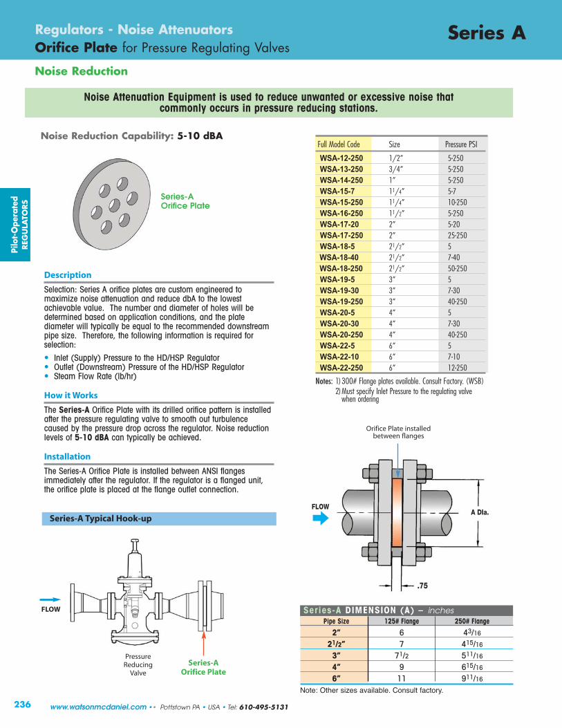
236
Noise Reduction
Series ARegulators - Noise AttenuatorsOrifice Plate for Pressure Regulating Valves
Noise Attenuation Equipment is used to reduce unwanted or excessive noise that commonly occurs in pressure reducing stations.
Series-A DIMENSION (A) – inches Pipe Size 125# Flange 250# Flange 2” 6 43/16 21/2” 7 415/16 3” 71/2 511/16 4” 9 615/16 6” 11 911/16
Note: Other sizes available. Consult factory.
PressureReducing
Valve
Series-A Typical Hook-up
Noise Reduction Capability: 5-10 dBA
Description
Selection: Series A orifice plates are custom engineered tomaximize noise attenuation and reduce dbA to the lowestachievable value. The number and diameter of holes will bedetermined based on application conditions, and the platediameter will typically be equal to the recommended downstreampipe size. Therefore, the following information is required forselection:
• Inlet (Supply) Pressure to the HD/HSP Regulator• Outlet (Downstream) Pressure of the HD/HSP Regulator• Steam Flow Rate (lb/hr)
How it Works
The Series-A Orifice Plate with its drilled orifice pattern is installedafter the pressure regulating valve to smooth out turbulencecaused by the pressure drop across the regulator. Noise reductionlevels of 5-10 dBA can typically be achieved.
Installation
The Series-A Orifice Plate is installed between ANSI flangesimmediately after the regulator. If the regulator is a flanged unit,the orifice plate is placed at the flange outlet connection.
Series-AOrifice Plate
FLOWA DIa.
.75
Orifice Plate installed between flanges
FLOWFLOW
Series-AOrifice Plate
Full Model Code Size Pressure PSI
WSA-12-250 1/2” 5-250WSA-13-250 3/4” 5-250WSA-14-250 1” 5-250WSA-15-7 11/4” 5-7WSA-15-250 11/4” 10-250WSA-16-250 11/2” 5-250WSA-17-20 2” 5-20WSA-17-250 2” 25-250WSA-18-5 21/2” 5WSA-18-40 21/2” 7-40WSA-18-250 21/2” 50-250WSA-19-5 3” 5WSA-19-30 3” 7-30WSA-19-250 3” 40-250WSA-20-5 4” 5WSA-20-30 4” 7-30WSA-20-250 4” 40-250WSA-22-5 6” 5WSA-22-10 6” 7-10WSA-22-250 6” 12-250
Notes: 1) 300# Flange plates available. Consult Factory. (WSB)2) Must specify Inlet Pressure to the regulating valve
when ordering
Pilo
t-O
pera
ted
REG
ULA
TORS
www.watsonmcdaniel.com •• Pottstown PA • USA • Tel: 610-495-5131
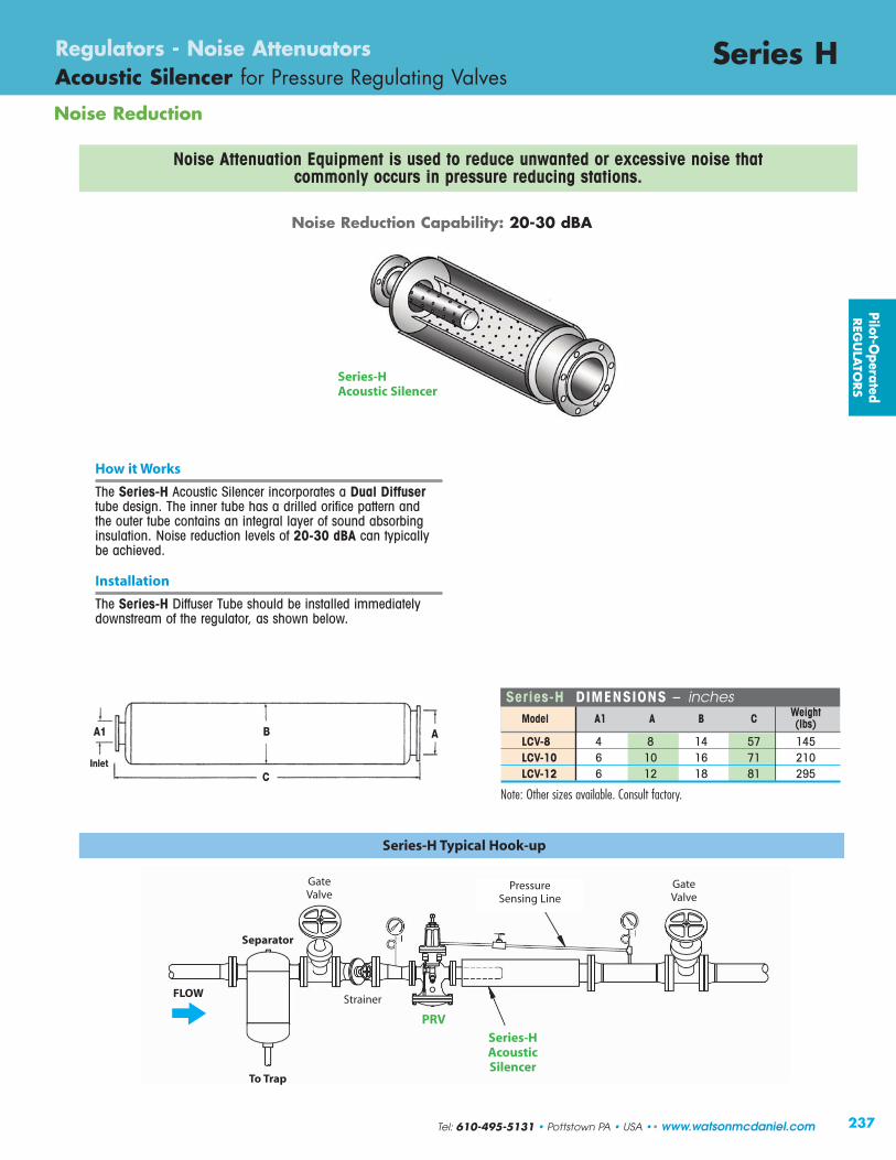
237
Series HRegulators - Noise AttenuatorsAcoustic Silencer for Pressure Regulating Valves
Noise Reduction
How it Works
The Series-H Acoustic Silencer incorporates a Dual Diffusertube design. The inner tube has a drilled orifice pattern andthe outer tube contains an integral layer of sound absorbinginsulation. Noise reduction levels of 20-30 dBA can typicallybe achieved.
Installation
The Series-H Diffuser Tube should be installed immediatelydownstream of the regulator, as shown below.
Series-HAcoustic Silencer
Series-H Typical Hook-up
Separator
PRV
Series-HAcoustic Silencer
PressureSensing Line
Series-H DIMENSIONS – inches Model A1 A B C Weight (lbs) LCV-8 4 8 14 57 145 LCV-10 6 10 16 71 210 LCV-12 6 12 18 81 295
Note: Other sizes available. Consult factory.
Noise Attenuation Equipment is used to reduce unwanted or excessive noise that commonly occurs in pressure reducing stations.
C
BA1 A
Inlet
Gate Valve
Gate Valve
Strainer
To Trap
FLOW
Noise Reduction Capability: 20-30 dBA
Pilot-Operated
REG
ULA
TORS
Tel: 610-495-5131 • Pottstown PA • USA •• www.watsonmcdaniel.com
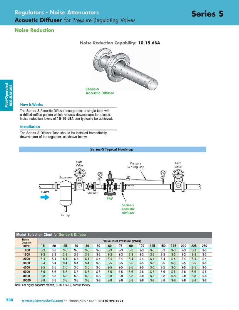
238
Noise Reduction
Series SRegulators - Noise AttenuatorsAcoustic Diffuser for Pressure Regulating Valves
Model Selection Chart for Series-S Diffuser
Valve Inlet Pressure (PSIG)15 20 25 30 40 50 60 75 90 100 125 150 175 200 225 250
1000 S-3 S-3 S-3 S-3 S-3 S-3 S-3 S-3 S-3 S-3 S-3 S-3 S-3 S-3 S-3 S-31500 S-3 S-3 S-3 S-3 S-3 S-3 S-3 S-3 S-3 S-3 S-3 S-3 S-3 S-3 S-3 S-32000 S-4 S-4 S-4 S-4 S-4 S-4 S-4 S-4 S-4 S-4 S-4 S-4 S-4 S-4 S-4 S-43000 S-4 S-4 S-4 S-4 S-4 S-5 S-5 S-5 S-5 S-5 S-5 S-5 S-5 S-5 S-5 S-5 4000 S-5 S-5 S-5 S-5 S-5 S-5 S-5 S-5 S-5 S-5 S-5 S-5 S-5 S-5 S-5 S-5 6000 S-6 S-6 S-6 S-6 S-6 S-6 S-6 S-6 S-6 S-6 S-6 S-6 S-6 S-6 S-6 S-6 8000 S-8 S-8 S-8 S-8 S-8 S-8 S-8 S-8 S-8 S-8 S-8 S-8 S-8 S-8 S-8 S-810000 S-8 S-8 S-8 S-8 S-8 S-8 S-8 S-8 S-8 S-8 S-8 S-8 S-8 S-8 S-8 S-8
Note: For higher capacity models, S-10 & S-12, consult factory.
SteamCapacity(lbs/hr)
Series-SAcoustic Diffuser
How it Works
The Series-S Acoustic Diffuser incorporates a single tube with a drilled orifice pattern which reduces downstream turbulence.Noise reduction levels of 10-15 dBA can typically be achieved.
Installation
The Series-S Diffuser Tube should be installed immediatelydownstream of the regulator, as shown below.
Series-S Typical Hook-up
Separator
PRV
GateValve
GateValve
Strainer
To Trap
FLOW
Noise Reduction Capability: 10-15 dBA
Series-SAcoustic Diffuser
PressureSensing Line
Pilo
t-O
pera
ted
REG
ULA
TORS
www.watsonmcdaniel.com •• Pottstown PA • USA • Tel: 610-495-5131

239
Series SRegulators - Noise AttenuatorsAcoustic Diffuser for Pressure Regulating Valves
Noise Reduction
Series-S DIMENSIONS – inches
Inlet (A) Outlet NPT x Weld Dimensions
NPT FLG FLG/BW B C D
S-33/4 2 51/2 131/2 23/81 2 51/2 131/2 23/8
3/4 4 61/2 131/2 41/21 4 61/2 131/2 41/2
S-4 11/4 4 61/2 131/2 41/211/2 4 61/2 131/2 41/2
2 4 61/2 131/2 41/23/4 4 61/2 161/2 41/21 4 61/2 161/2 41/2
S-5 11/4 4 61/2 161/2 41/211/2 4 61/2 161/2 41/2
2 4 61/2 161/2 41/221/2 21/2 4 61/2 161/2 41/211/4 6 8 14 55/811/2 6 8 14 55/8
S-6 2 6 8 14 55/821/2 21/2 6 8 14 55/8
3 3 6 8 14 55/811/2 8 10 17 85/8
2 8 10 17 85/8S-8 21/2 21/2 8 10 17 85/8
3 3 8 10 17 85/84 4 8 10 17 85/82 12 12 14 123/4
21/2 21/2 12 12 14 123/4S-10 3 3 12 12 14 123/4
4 4 12 12 14 123/46 6 12 12 14 123/4
21/2 21/2 12 12 21 123/4
S-12 3 3 12 12 21 123/44 4 12 12 21 123/46 6 12 12 21 123/4
Notes: 1)150# & 300# flanged available.2) Other sizes available; consult factory.
Model
NPT x Butt-Weld
Flanged x Butt-Weld
NPT x Flanged
Flanged x Flanged
D
BC
(A)InletNPT
Pilot-Operated
REG
ULA
TORS
BW = Butt-weld
Tel: 610-495-5131 • Pottstown PA • USA •• www.watsonmcdaniel.com
OutetBW
(A)Inlet
Flanged
OutetBW
(A)InletNPT
OutetFlanged
(A)Inlet
FlangedOutetFlanged
FLOW

240
InletPressure(PSIG)
OutletPressure(PSIG)
Cv Factors
1/2" 3/4" 1" 11/4" 11/2" 2" 21/2" 3" 4" 6"
3.8 6.7 11 15 21 37 55 71 113 241
CAPACIT IES – Steam (lbs/hr) FULL PORT
5 0 85 150 250 350 500 800 1200 1600 2600 5500 2 80 140 230 310 440 770 1100 1500 2400 5100 0 115 200 325 450 600 1100 1650 2100 3600 7800 7 2 105 180 300 400 575 1000 1500 2000 3100 6700 3 90 160 275 375 525 900 1300 1800 2800 6000 0 150 260 425 575 850 1500 2200 2800 4600 9900 10 2 140 240 400 550 800 1400 2100 2700 4300 9100
5 100 175 300 400 600 1000 1600 2000 3200 6900 0 160 280 475 600 900 1600 2400 3100 4900 10300 12 4 140 240 400 550 800 1400 2100 2700 4300 9100
7 125 200 375 500 700 1200 1900 2400 3800 8200 0-3 190 325 550 750 1000 1800 2700 3500 5600 12000 15 5 175 300 500 700 900 1700 2500 3200 5200 11100 8 140 250 400 500 800 1300 2000 2600 4200 8900 0-5 210 375 625 850 1200 2100 3100 4000 6400 13700 20 10 190 325 550 750 1000 1800 2700 3500 5600 12000 12 170 300 500 675 950 1600 2500 3200 5100 10800 0-7 250 450 775 1050 1500 2600 3800 5000 7900 16900 25 10 225 425 700 975 1300 2400 3600 4600 7300 15600 15 200 350 600 800 1100 2000 3000 3900 6200 13200 0-12 275 500 800 1100 1500 2700 4100 5200 8300 17800 30 15 250 450 750 1000 1400 2500 3800 4900 7800 16600 20 225 375 650 850 1200 2100 3200 4100 6500 14000 0-18 350 600 1000 1350 1900 3300 5000 6400 10300 21900 40 25 300 500 850 1150 1600 2800 4200 5400 8700 18500 30 250 425 700 1000 1400 2500 3700 4700 7600 16100 0-20 400 700 1200 1650 2300 4100 6000 7800 12400 26500 50 30 350 650 1100 1500 2000 3600 5400 6900 11000 23600 40 275 500 800 1100 1500 2700 4100 5200 8300 17800 0-30 475 850 1350 1900 2600 4600 6900 8900 14200 30300 60 35 425 775 1250 1700 2400 4300 6400 8200 13100 27900 50 300 525 850 1200 1600 2900 4300 5600 8900 19000 0-35 575 1000 1650 2300 3200 5600 8300 10800 17200 36600 75 50 475 825 1350 1900 2600 4600 6900 8900 14100 30100 60 400 700 1150 1600 2200 3900 5800 7400 11800 25200 0-45 675 1200 1950 2700 3700 6600 9800 12700 20200 43100 90 60 575 1000 1700 2300 3200 5700 8500 10900 17400 37100 75 425 750 1200 1700 2300 4100 6100 7900 12600 27000 0-50 750 1300 2100 3000 4100 7300 10800 14000 22200 47500 100 60 700 1200 2000 2700 3800 6700 10000 12900 20500 43800 80 500 875 1400 1900 2700 4800 7100 9200 14700 31300 0-60 925 1650 2700 3700 5200 9100 14000 17500 28000 59500 125 75 825 1475 2400 3300 4600 8200 12200 15700 25000 53500 100 625 1100 1800 2500 3500 6200 9200 11900 19000 40400 0-75 1100 1900 3100 4300 6000 10600 15800 20400 32400 69100 150 100 925 1600 2700 3600 5100 9000 13400 17400 27700 59000 125 650 1150 1900 2600 3600 6400 9500 12300 19600 41900 0-85 1275 2250 3700 5000 7100 12500 18600 24000 38200 81400 175 125 1000 1800 2900 4000 5600 9900 14700 18900 30100 64300 150 750 1300 2100 2900 4100 7300 10800 14000 22200 47500 0-100 1450 2500 4200 5700 8000 14100 21000 27100 43100 92000 200 125 1300 2300 3700 5100 7100 12600 18700 24100 38400 81900 150 1075 1900 3100 4300 6000 10600 15700 20300 32300 68900 0-120 1575 2800 4600 6200 8700 15400 22900 29500 47000 100200 225 150 1450 2500 4200 5700 8000 14100 21000 27200 43300 92300 175 1350 2400 3900 5300 7400 13100 19500 25200 40100 85500 0-130 1750 3100 5100 6900 9700 17100 25500 32900 53400 111800 250 150 1650 2900 4700 6500 9100 16000 23800 30800 49000 104600 200 1200 2100 3500 4800 6700 11900 17600 22800 36200 77300 0-160 2045 3605 5920 8075 11310 19220 29610 38230 60840 129750
300 175 1945 3425 5625 7670 10740 18925 28130 36320 57800 123270 200 1780 3140 5155 7030 9840 17340 25780 33275 52960 112950 0-200 7980 1480 22000 48800 78000 400 250 7550 13800 23800 46200 73950 300 6700 12100 21200 41000 65200 0-225 8970 16000 22000 55000 87600
450 300 8500 15000 26900 52100 83200 350 7540 13300 23900 46200 73900
Note: For inlet pressures in green shaded area, use low pressure main valve and low pressure temperature pilot. For 400 & 450 PSIG inlet pressures, use HSP regulator only.
HD & HSP SeriesRegulators Capacity Charts
Pilo
t-O
pera
ted
REG
ULA
TORS
Full Port
www.watsonmcdaniel.com •• Pottstown PA • USA • Tel: 610-495-5131

241
Note: For inlet pressures in green shaded area, use low pressure main valve and low pressure temperature pilot. For 400 & 450 PSIG inlet pressures, use HSP regulator only.
InletPressure(PSIG)
OutletPressure(PSIG)
Cv Factors
1/2" 3/4" 1" 11/4" 11/2" 2" 21/2" 3" 4" 6"
1.4 3.3 5.6 7.8 13.3 18.8 25.9 41.7 74 163
CAPACIT IES – Steam (lbs/hr) REDUCED PORT
5 0 15 35 59 82 140 197 272 438 777 1712 2 13 32 53 75 128 181 249 401 712 1569 0 21 48 82 115 195 276 381 613 1088 2396 7 2 20 46 79 110 187 265 365 587 1042 2296 3 19 44 74 104 177 250 344 554 983 2165 0 29 70 117 164 279 395 544 876 1554 3423 10 2 28 68 115 160 274 387 533 858 1523 3354 5 25 60 102 142 242 342 471 758 1346 2964 0 35 83 141 197 335 473 653 1051 1865 4108 12 4 33 78 133 185 316 446 615 990 1758 3873 7 29 68 115 160 272 385 530 854 1515 3336 0-3 43 102 173 241 410 580 800 1287 2284 5031 15 5 41 98 166 232 395 558 769 1238 2198 4841 8 37 88 149 208 354 500 690 1111 1972 4343 0-5 57 134 227 317 541 764 1053 1696 3009 6629 20 10 51 120 204 284 483 684 942 1517 2692 5929 12 47 111 188 262 447 632 870 1401 2486 5477 0-7 70 166 282 393 670 948 1305 2102 3730 8215 25 10 67 158 269 375 640 905 1246 2006 3561 7843 15 59 139 235 328 559 790 1088 1751 3108 6846 0-12 81 190 323 450 768 1085 1495 2408 4273 9411 30 15 76 180 305 426 726 1025 1413 2275 4037 8892 20 66 155 263 366 625 883 1216 1958 3475 7654 0-18 105 248 420 585 998 1410 1943 3128 5551 12227 40 25 99 199 367 511 872 1232 1698 2734 4852 10688 30 78 183 311 433 739 1044 1439 2317 4111 9056 0-20 135 318 539 751 1280 1809 2492 4013 7121 15686 50 30 118 277 470 655 1117 1579 2175 3502 6216 13692 40 88 208 353 491 838 1184 1632 2627 4662 10269 0-30 153 360 611 851 1451 2051 2826 4550 8074 17786 60 35 143 338 573 798 1361 1924 2651 4268 7573 16682 50 98 230 390 543 926 1309 1804 2904 5154 11353 0-35 195 460 780 1086 1853 2619 3608 5809 10308 22706 75 50 164 387 657 916 1561 2207 3040 4895 8687 19135 60 132 312 529 737 1257 1777 2448 3941 6993 15404 0-45 229 540 916 1277 2177 3077 4239 6825 12112 26680 90 60 197 465 789 1100 1874 2648 3649 5874 10425 22962 75 146 345 585 815 1389 1964 2705 4357 7731 17029 0-50 255 600 1018 1419 2419 3419 4710 7584 13458 29644 100 60 235 554 940 1310 2234 3158 4351 7006 12432 27384 80 176 416 706 983 1676 2367 3263 5254 9324 20538 0-60 322 760 1290 1796 3063 4329 5964 9603 17041 37536 125 75 294 693 1176 1638 2793 3948 5439 8757 15540 34230 100 221 518 882 1229 2095 2961 4079 6568 11655 25672 0-75 381 900 1527 2128 3628 5128 7065 11376 20187 44467 150 100 329 775 1315 1831 3123 4414 6081 9791 17374 38270 125 243 575 975 1385 2316 3274 4510 7261 12885 28382 0-85 449 1060 1800 2505 4272 6939 8320 13396 23771 52362 175 125 360 849 1440 2006 3421 4835 6661 10725 19032 41923 150 265 625 1060 1476 2518 3558 5606 7893 14008 30855 0-100 509 1200 2037 2837 4838 6838 9420 15168 26916 59288 200 125 459 1082 1836 2557 4360 6164 8492 13672 24262 53442 150 389 917 1556 2167 3695 5223 7195 11584 20557 45232 0-120 560 1319 2238 3117 5360 7514 10351 16667 29577 65150 225 150 493 1162 1972 2747 4684 6621 9121 14686 26061 57405 175 416 980 1663 2316 3950 5583 7692 12384 21976 48409 0-130 628 1480 2511 3498 5964 8431 11614 18700 33184 73095 250 150 588 1386 2352 3276 5586 7896 10878 17514 31080 68460 200 441 1040 1764 2457 4190 5922 8159 13136 23310 51345 0-160 755 1775 3015 4200 7160 10120 13945 22450 39840 87760
300 175 715 1690 2865 3990 6800 9615 13250 21330 37850 83370 200 655 1550 2625 3655 6235 8810 12140 19545 34680 76400 0-200 4070 9460 24500 29980 51450 400 250 3860 8970 12380 27460 48750 300 3430 7970 11010 24410 43330 0-225 4580 10650 24500 32600 57890
450 300 4340 10090 13930 30890 54840 350 3860 8970 12380 27460 48750
HD & HSP SeriesRegulators Capacity Charts
Pilot-Operated
REG
ULA
TORS
Reduced Port
Tel: 610-495-5131 • Pottstown PA • USA •• www.watsonmcdaniel.com