Pilot models in full missions simulation of JAS 39...
52
Pilot models in full missions simulation of JAS 39 Gripen ERIK GRÖNDAHL Master of Science Thesis Stockholm, Sweden 2013
Transcript of Pilot models in full missions simulation of JAS 39...

Pilot models in full missions simulation of JAS 39 Gripen
E R I K G R Ö N D A H L
Master of Science Thesis Stockholm, Sweden 2013


Pilot models in full missions simulation of JAS 39 Gripen
E R I K G R Ö N D A H L
Master’s Thesis in Systems Engineering (30 ECTS credits) Master Programme in Aerospace Engineering (120 credits) Royal Institute of Technology year 2013 Supervisor at SAAB was Johan Enhagen
Supervisor at KTH was Per Enqvist Examiner was Per Engvist TRITA-MAT-E 2013:53 ISRN-KTH/MAT/E--13/53--SE Royal Institute of Technology School of Engineering Sciences KTH SCI SE-100 44 Stockholm, Sweden URL: www.kth.se/sci


Abstra tThis master thesis was performed at the se tion of Flight Me hani s andPerforman e at SAAB Aeronauti s in Linköping as a part of my Master ofS ien e in Engineering Physi s at KTH, Sto kholm. The aim of the thesisis to enable desktop simulations of missions from take-o� to landing of JAS39 Gripen.The mission is set up by a series of task to be performed. Ea h tasksthen link to a pilot model that ontrols the air raft to perform the giventask. The main part of the work has been to reate these pilot models as anextension of the work by Ajdén and Ba klund presented in [1℄.The tasks that are simulated are, take-o�, limb, turn, ruise, ombatsimulation, des ent and landing at a given point. In order to perform thesetasks both open and losed loop ontrols are used. To perform the landing�rst a path planing based on Dubins minimum path is al ulated and thenthe nonlinear guidan e logi presented by Park, Desyst and How in [5℄ isimplemented and used for traje tory tra king.The results from a simulation of a test mission are presented and showsthat mission simulations are possible and that the pilot models perform theintended tasks. SammanfattningDetta examensarbete utfördes vid sektionen för Flygmekanik o h pre-standa på SAAB Aeronauti s i Linköping som del av min ivilingenjörs exa-men i tekniskfysik på KTH, Sto kholm. Det huvudsakliga målet med arbetetär att möjliggöra simuleringar av uppdrag från start till landning för JAS39 Gripen.Uppdraget beskrivs av ett antal uppgifter som �ygplanet ska utföra somsätt ihop i en serie. Varje uppgift kopplas till en modell av en pilot somsimulerar vilka kommandon som en pilot skulle ge för att styra �ygplanetså att det utför uppgiften. Detta har gjorts genom att bygga vidare på depilotmodeller som skapades av Ajdén o h Ba klund i [1℄.De uppgifter som har skapats o h kan simulerars i ett uppdrag är: start,stigning, kurshållning, stridssimulering, nedstigning o h landning på givenpunkt. För att kunna simulera dessa uppgifter har både öppen o h återkop-plad reglering används. I uppgiften att landa på en given punkt beräknasförst en bana att följa som använder sig av Dubins kortaste väg o h sedan an-vänds den i kelinjära ban�öjnings algoritmen som beskrivs av Park, Desysto h How i [5℄ för att följa banan.Resultatet av en simulering av ett test uppdrag presenteras o h visar attuppdrags simuleringar är möjliga o h att pilotmodellerna kan simulera degivna uppgifterna. 1


A knowledgementsI would like to thank everyone at SAAB who has helped and supported me inmy thesis work. I would espe ially like to thank, Mårten Sta� and my supervisorJohan Enhagen without whom the work would not have been possible.Erik GröndahlSto kholm, November 4, 2013
2


CONTENTS CONTENTSContents1 Introdu tion 71.1 Ba kground . . . . . . . . . . . . . . . . . . . . . . . . . . . . . . . 71.2 Obje tives . . . . . . . . . . . . . . . . . . . . . . . . . . . . . . . . 81.3 Previous work . . . . . . . . . . . . . . . . . . . . . . . . . . . . . . 92 Methods 102.1 General movement . . . . . . . . . . . . . . . . . . . . . . . . . . . 102.2 Take-o� . . . . . . . . . . . . . . . . . . . . . . . . . . . . . . . . . 112.3 Climb . . . . . . . . . . . . . . . . . . . . . . . . . . . . . . . . . . 112.3.1 Level out without roll . . . . . . . . . . . . . . . . . . . . . 122.3.2 Level out with roll . . . . . . . . . . . . . . . . . . . . . . . 132.3.3 Move on to next blo k . . . . . . . . . . . . . . . . . . . . . 132.4 Turn to given ourse angle . . . . . . . . . . . . . . . . . . . . . . . 132.5 Cruise . . . . . . . . . . . . . . . . . . . . . . . . . . . . . . . . . . 142.6 Combat simulation . . . . . . . . . . . . . . . . . . . . . . . . . . . 152.6.1 Flying in a �gure 8 . . . . . . . . . . . . . . . . . . . . . . . 152.7 Des ent . . . . . . . . . . . . . . . . . . . . . . . . . . . . . . . . . 152.7.1 Des ent without roll . . . . . . . . . . . . . . . . . . . . . . 162.7.2 Des ent with roll . . . . . . . . . . . . . . . . . . . . . . . . 162.7.3 Level out and move to next blo k . . . . . . . . . . . . . . . 162.8 Landing . . . . . . . . . . . . . . . . . . . . . . . . . . . . . . . . . 162.8.1 γ and α ontrol . . . . . . . . . . . . . . . . . . . . . . . . . 172.8.2 Guidan e law . . . . . . . . . . . . . . . . . . . . . . . . . . 182.8.3 Altitude ontrol . . . . . . . . . . . . . . . . . . . . . . . . . 212.8.4 Finding a �yable path in the plane . . . . . . . . . . . . . . 212.8.5 Landing pro edure . . . . . . . . . . . . . . . . . . . . . . . 253 Results 273.1 Test mission . . . . . . . . . . . . . . . . . . . . . . . . . . . . . . . 273.2 Take-o� . . . . . . . . . . . . . . . . . . . . . . . . . . . . . . . . . 293.3 Climb . . . . . . . . . . . . . . . . . . . . . . . . . . . . . . . . . . 293.3.1 Without roll . . . . . . . . . . . . . . . . . . . . . . . . . . . 293.3.2 With roll . . . . . . . . . . . . . . . . . . . . . . . . . . . . . 303.4 Turn to given ourse angle . . . . . . . . . . . . . . . . . . . . . . . 313.5 Cruise . . . . . . . . . . . . . . . . . . . . . . . . . . . . . . . . . . 323.5.1 Altitude hold . . . . . . . . . . . . . . . . . . . . . . . . . . 323.5.2 Gamma hold . . . . . . . . . . . . . . . . . . . . . . . . . . 333.6 Combat simulation . . . . . . . . . . . . . . . . . . . . . . . . . . . 333.7 Des ent . . . . . . . . . . . . . . . . . . . . . . . . . . . . . . . . . 353.7.1 With roll . . . . . . . . . . . . . . . . . . . . . . . . . . . . . 353.7.2 Without roll . . . . . . . . . . . . . . . . . . . . . . . . . . . 353.8 Landing . . . . . . . . . . . . . . . . . . . . . . . . . . . . . . . . . 353

CONTENTS CONTENTS4 Dis ussion 384.1 Take-o� . . . . . . . . . . . . . . . . . . . . . . . . . . . . . . . . . 384.2 Climb . . . . . . . . . . . . . . . . . . . . . . . . . . . . . . . . . . 384.2.1 Without roll . . . . . . . . . . . . . . . . . . . . . . . . . . . 384.2.2 With roll . . . . . . . . . . . . . . . . . . . . . . . . . . . . . 384.3 Turn to given ourse angle . . . . . . . . . . . . . . . . . . . . . . . 394.4 Cruise . . . . . . . . . . . . . . . . . . . . . . . . . . . . . . . . . . 394.4.1 Altitude hold . . . . . . . . . . . . . . . . . . . . . . . . . . 394.4.2 Gamma hold . . . . . . . . . . . . . . . . . . . . . . . . . . 394.5 Combat simulation . . . . . . . . . . . . . . . . . . . . . . . . . . . 394.6 Des ent . . . . . . . . . . . . . . . . . . . . . . . . . . . . . . . . . 404.6.1 With roll . . . . . . . . . . . . . . . . . . . . . . . . . . . . . 404.6.2 Without roll . . . . . . . . . . . . . . . . . . . . . . . . . . . 404.7 Landing . . . . . . . . . . . . . . . . . . . . . . . . . . . . . . . . . 404.7.1 Guidan e law . . . . . . . . . . . . . . . . . . . . . . . . . . 404.7.2 α and γ ontrol . . . . . . . . . . . . . . . . . . . . . . . . . 404.8 Full mission . . . . . . . . . . . . . . . . . . . . . . . . . . . . . . . 415 Con lusions 42
4

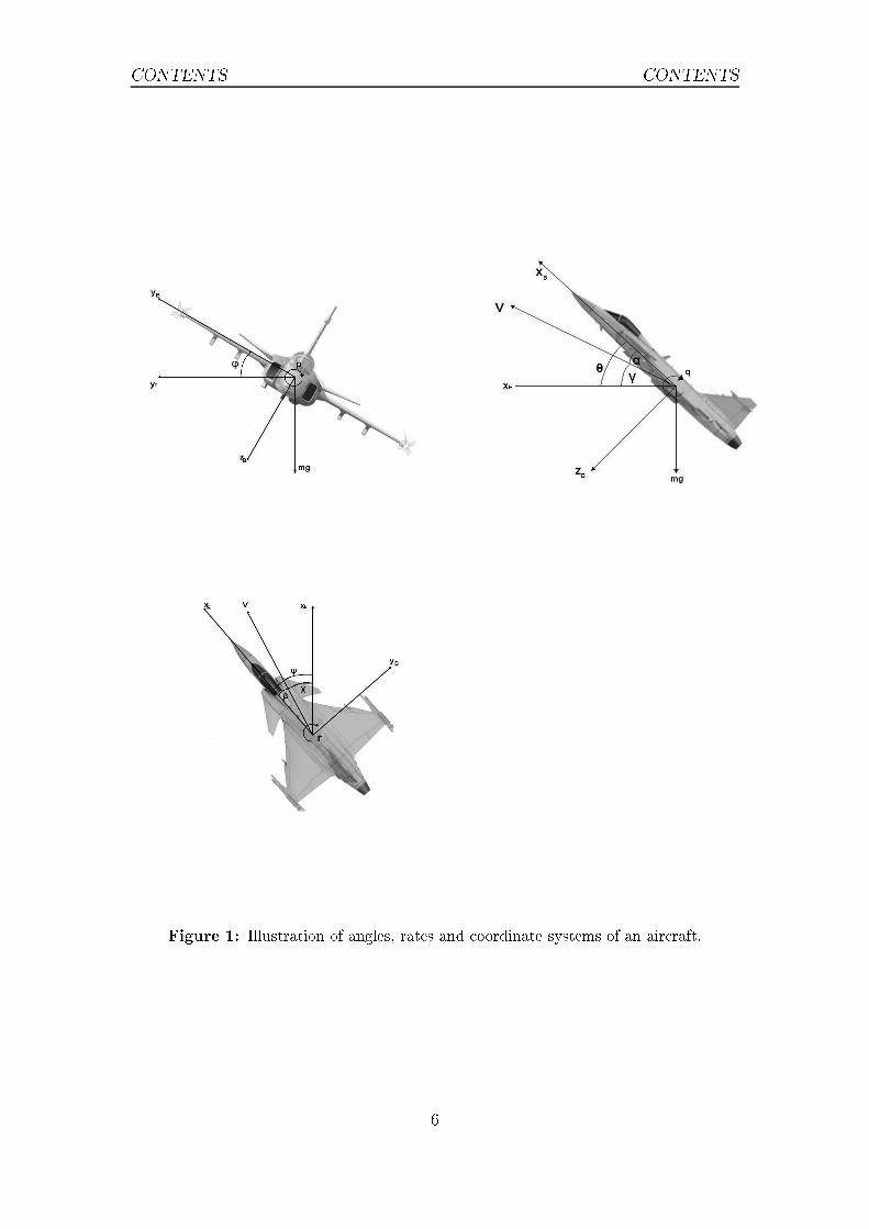
CONTENTS CONTENTSNomen lature and abbreviationsα Angle of atta kβ Slide-slip angleγ Climb/Des ent angleχ Course angleθ Pit h angleϕ Roll angleΨ Yaw anglep Roll rateq Pit h rater Yaw ratexb, yb, zb Body �xed oordinate systemxe, ye, ze Earth �xed oordinate systemv Speed of air raftM Ma h number (v/(speed of sound at altitude))m Mass of air raftg Gravitational onstantρ Air density at urrent altitudeS Aerodynami referen e areaa/ Air raftBOT Bleed Of TurnCMC Constant Ma h ClimbCSC Cir le-Straight-Cir le
5
CONTENTS CONTENTS
Figure 1: Illustration of angles, rates and oordinate systems of an air raft.6

1 INTRODUCTION1 Introdu tion1.1 Ba kgroundIn air raft (a/ ) development simulations are used to determine the behaviour ofthe di�erent systems in the a/ . These simulations an be arried out either in a�ight simulator or in a desktop simulation environment (in this ase the programARES). When simulations are arried-out in a �ight simulator a pilot is used to�y the simulator, while if the simulations are done in a desktop environment, notonly the air raft and all it subsystems need to be simulated, but also the pilotneeds to be modelled.In the development of the �ghter 39 Gripen, SAAB needs to know how the vari-ous subsystems work both in a short time period, a single manoeuvre, and in longertime periods, a full mission from take-o� to landing. In order to test the longer timeperiods SAAB has de�ned a number of full-length test missions to be simulated.Today these missions are �own in a �ight simulator using a real pilot. This meansthat missions an only be simulated in real time whi h makes this time onsuming.For shorter time-periods both simulations in ARES and simulations in a �ightsimulator with a real pilot are available. When using desktop simulations the pilotmodels (used to simulate the pilot) that are urrently available at SAAB are mainly onstru ted to ontrol the a/ towards a given value in, for example ϕ, α or γ andin some few ases to perform a task su h as take-o� or make a onstant Ma h limb.Most of the pilot models used in this work were onstru ted by Ajdén and Ba k-lund [1℄, using LQ- ontrol and pole pla ement te hniques. These pilot models an ontrol:• Roll rate• Roll attitude• Pit h rate• Pit h attitude• Yaw rate• Yaw attitude• Angle of atta k• Climb angle• Climb rate• Ma h number 7

1.2 Obje tives 1 INTRODUCTION• Load fa torMore task driven pilot models ( onstru ted by [1℄) an perform a "Bleed O�Turn" (BOT), where the load fa tor is given and the a/ is kept at a onstantaltitude by ontrolling the roll angle and a onstant Ma h limb (CMC) where thea/ , given a onstant throttle position, keeps the Ma h number to a given value by ontrolling the limb angle. There also exist a pilot model that performs a take-o�that was onstru ted by SAAB.1.2 Obje tivesThis thesis aims at enabling full mission simulations in ARES for the air raft 39Gripen. In order to do this pilot models to perform tasks will be designed. Theoutput of these new models will be used as input to the existing pilot models.These task driven pilot models (blo ks) should be onne ted in series in orderto set up a full mission for simulations in ARES and the movement between theblo ks should be done in su h a way that the dynami s of the a/ is ontinuousthrough out the simulation.These obje tives means that there are a number of di�erent problems that needsto be solved. Firstly, a number of di�erent blo ks are needed in order to solvethe tasks of a mission. Se ondly, some of the tasks needs to hange settings thatin ARES are not allowed to be set by a pilot model (ex. pulling in and out thelanding gear and releasing external loads). Thirdly, moving between the tasks andensuring that the a/ dynami s are ontinuous through out the simulation.To solve the tasks of a mission the following blo ks are reated in this thesis:• Take-o�• Climb to given altitude• A elerate to a onstant speed• Fly at onstant altitude and speed• Combat simulation• Turn• Des ent to given altitude• Land at point (x,y) with a given ourse angleThe �nal obje tive is to set up a full mission from take-o� to landing using thedesigned blo ks and then to simulate it in ARES. In this thesis an example of amission will be �own in the ARES 39 Gripen simulation model. The true testmissions of SAAB annot be revealed due to se urity reasons.8

1.3 Previous work 1 INTRODUCTION1.3 Previous workIn order to simulate a mission from take-o� to landing the total simulated systemis an be said to onsist of three part. First a list of task to be performed whi hin sequen e be omes the desired mission. Then a pilot part whi h ommands thea/ and de ides how to perform a given task and when a task is onsidered doneand lastly a a/ part whi h simulates how the a/ behaves.This way of dividing the part of the simulations is similar to [4℄. The di�eren emostly lies in that in this work some of the properties of the task blo k in [4℄ hasbeen moved to the pilot blo k in [4℄.
9

2 METHODS2 MethodsThe method of this work has been to identify ea h task in the mission and then reate one or more blo ks to ful�l the requirements. In this se tion ea h task willbe dis ussed and the ontrol logi that governs the blo k will be presented.The ontrol logi will give value to at least one of αref , γref , href , ϕref , χref ,Ψrefor Mref that are then used as input to the pilot model design by Ajdén and Ba k-lund [1℄ or use existing task driven pilot models.The blo ks will be presented in the order that they appear in the mission thatis presented in the blo k diagram in Figure 2.Take-O�Climb Turn Cruise CombatDes entLandingFigure 2: Blo k diagram of a mission.2.1 General movementAs the a/ is �ying a mission there are a number of di�erent onstraint to take into onsideration. Some onstraints are hard and are handled either by the perfor-man e of the a/ (ex. the maximum Ma h number) or by the a/ ontrol system(ex. maximum and minimum load-fa tor allowed). The hard onstraints are ig-nored by the blo ks onstru ted. This means that, if the user sets a blo k tryingto �y to a point outside the �ight envelop the pilot-model will still try to rea hthat point.Other onstraints are softer and are introdu ed in order to simulate how a realpilot would behave. These onstraints are di�erent depending on the manoeuvrethat the pilot would like to perform and are individual for ea h blo k.The initial ondition of ea h blo k are free (ex ept for the take-o�) but all blo ksneed to have lear �nal onditions. The �nal onditions implemented an be di-vided into two di�erent types. The �rst type (external) an be set to any blo kand on e true the mission will move to the next blo k. These ondition an be oneof the parameters presented below.
• Time from start• Time in blo k 10

2.2 Take-o� 2 METHODS• Distan e �own in blo k• Altitude [above/below℄• Ma h number [above/below℄• Speed [above/below℄• Climb/Des ent angle (γ) [±0.06◦℄• Roll angle (ϕ) [±0.06◦℄• Course angle (χ) [±0.06◦℄If Altitude, Ma h number or Speed is set as a �nal ondition then either above orbelow the referen e value an be hosen. For χ, γ or ϕ the onstraint is a tivatedif the value is within ±0.06◦ of the referen e value.The other type of �nal ondition (internal) are built into the blo k. This typeof �nal onditions are more ompli ated, and may onsist of a number of di�erent onditions having to be met. As these onditions depend on what kind of manoeu-vre is being performed they will be presented in the des ription of ea h blo k.2.2 Take-o�At the start of the mission the a/ has to take-o� (unless the mission is startedin mid air). This pilot-model was onstru ted by SAAB and uses three PID- ontrollers to ontrol Ψ = 0◦, ϕ = 0◦ and, depending on the user settings al ulatewhen to start rotating and ontrol θ to θref .This blo k also needs to pull-in the landing gear, as mentioned earlier this annotbe done inside the pilot model. The solution to this is to keep tra k of whi h blo kthat is urrently being simulated and then when moving to the next blo k startpulling in the landing gear. This blo k does not have any internal �nal onditionand so one of the external �nal onditions has to be set.2.3 ClimbThe task to limb to a given altitude an be done in a number of di�erent ways.Firstly any limb an be divided into two di�erent parts, the general limb partand the levelling out part. In the general limb part, a pilot-model keeps the a/ limbing in one of the following ways. Keep γ or h to a given referen e value, makea CMC or make a more ompli ated limb where the a/ �rst limbs keeping a onstant speed and then as the Ma h number of the a/ rea hes a referen e value
Mref the a/ starts on a CMC at the Ma h number Mref .11

2.3 Climb 2 METHODSThe γref and href limbs an be handled dire tly by the pilot-model reated byAjdén and Ba klund and as stated in Se tion 1.1 a CMC pilot-model also exists.For the limb whi h �rst is performed with a onstant speed and then with a on-stant Ma h number, the following logi is introdu ed. First the referen e value inspeed is onverted into a referen e in Ma h number Mref2 at the urrent altitude,then if Mref2 < Mref the CMC pilot-model is used with Mref2 as its referen evalue, but if Mref2 ≥ Mref then Mref is used as the referen e value.The purpose of the levelling out part is to ontrol the a/ to the �nal onditionof the blo k. That is h = href , h = 0ms−1 and ϕ = 0◦. This initially requiresthe a/ to slow down in verti al speed. To do this pilots use one of two di�erentmanoeuvres. The �rst is to level out without a roll and the se ond is to level outwith a roll. Soft onstraints on the allowed nz are introdu ed to the blo k so thatmore or less aggressive levelling parts an be simulated. These onstraints will inthis blo k be referred to as nzminand nzmax
.2.3.1 Level out without rollFor the level out there are two separate problems to be solved. The �rst is tode ide when to start the level out and the se ond is to design the ontrol logi su h that the a/ rea hes the �nal onditions, h = href , h = 0ms−1 and ϕ = 0◦.In this ase, where there is no roll in the level out, the last �nal ondition may beignored as it is true during the whole manoeuvre.The a eleration in the ze dire tion is given by equation 1,az = nzg cos(θ)− g. (1)This means that the maximum allowed a eleration to slow down the verti al speedof the a/ is a hieved when nz = nzmin
. By assuming that θ ≈ 0◦ and that thea eleration an be a hieved instantly. The altitude distan e needed to slow thea/ down to h = 0ms−1 is ∆h whi h an be al ulated by equation 2,∆h = h2
2g(1−nzmin). (2)This means that the a/ needs to start to level out at an altitude of hlim =
href −∆h.During the level out h is hosen as the ontrol variable. The ontrol now needsto make sure that the a/ rea hes the �nal onditions h = href and h = 0ms−1and does not violate the onstraints nzmin≥ nz ≥ nzmax
.The ontroller used is des ribed in equation 3,herror = href − h
href = Kherror + P herrorwhere href ∈ [h− g(1− nzmin), h− g(1− nzmax
)]. (3)12

2.4 Turn to given ourse angle 2 METHODS2.3.2 Level out with rollThis way of performing the level out starts with the a/ rolling to ϕ = 180◦.When the a/ has rolled to ϕ = 180◦ it starts to slow down in the ze-dire tion.The a eleration in the ze dire tion (assuming cos(θ) = 1) is given by equation 4,az = −(g + gnz). (4)This means that the maximum allowed a eleration to slow down the verti alspeed of the a/ is a hieved when nz = nzmax
. The distan e needed for the levelout an then be al ulated with equation 5,∆h = h2
2g(1+nzmax ). (5)This means that the a/ needs to start to level out at an altitude of hlim =
href −∆h.To level out with roll the following ontrol logi is followed:First, the a/ is ontrolled towards ϕ = 180◦ and q = 0. Then when |ϕ| ≥ 135◦the a/ is ontrolled towards:ϕref = 180◦
herror = href − h
href = Kherror + P herrorwhere href ∈ [h− g(nzmax), h− g(nzmin
)]
(6)When |h| < 2ms−1, the a/ is ontrolled towards ϕref = 0◦ and h = 0ms−1,i.e the a/ will roll ba k and try and keep level �ight. In this phase of the levelout there is no ontrol on rea hing the orre t altitude, this is be ause the mainpurpose of this part is to get the a/ to ϕ = 0. When |ϕ| < 5◦ the ontroller inequation 3 is used to ontrol to the orre t altitude.2.3.3 Move on to next blo kIn both the limbs without and with roll endings the onditions for moving to thenext blo k in the mission are that |h| < 2ms−1 and that |herror| < 3m. There isalso the option to give one of the external �nal onditions.2.4 Turn to given ourse angleWhen �ying a mission turning and hanging ourse angle is important. As statedin Se tion 1.1, Ajdén and Ba klund reated a pilot-model that ould ontrol thea/ to a given χref . For this pilot-model to work, χref needs to be lose to the urrent value of χ. This ontrol is also slow due to the fa t that it only uses rudder ontrol. For these reasons a new ontrol logi was designed.13

2.5 Cruise 2 METHODSThe ontrol was designed in su h a way that the user sets a desired value of theload fa tor for the pilot to ontrol towards. If there is a desired altitude (href)to hold then a simple proportional ontrol was used in order to keep the altitude.The altitude ontrol is presented in equation 7,γref = −(h− href)/10. (7)If there is no desired altitude to hold the γref = 0◦.Now, in order to ontrol towards both a given value in γref and towards a givenload fa tor the pilot model performing a BOT is used. This means that the pilot-model may now turn the a/ and so, there is need for a logi to rea h and holdthe desired ourse angle.In the reated logi the turn dire tion an ether be set to the right,the left orthe shortest distan e. The shortest distan e ase the error to the right and leftare al ulated and the smallest value is hosen. Equation 8 des ribes the logi for ontinuing the BOT turn or if it is time to stop the turn, in the ases that theturn is a right turn. Here χerr > 0◦, χerr is the time derivative of the error and τis a time onstant.
χerr = χ− χref ± 2πn, s.t. χerr ∈ [0, 2π) and n ∈ Zχlim = χerr − χerrτif χlim < 0 then Stop turning.else Continue turning. (8)
De iding when to stop the turn is done a ording to equation 8. When the de i-sion to stop the turn has been made, ϕ is ontrolled towards 0◦. Then when, χerrbe omes small the pilot-model of [1℄ an be used to ontrol χ to χref . During thewhole turn throttle ontrol may be used in order to ontrol the Ma h number ofthe a/ to a referen e value.This blo k has internal �nal onditions that is is done when |χerr| < 1◦ and|re| < 1◦s−1.2.5 CruiseThe main idea of this blo k is to �y straight and level. To do this two di�erenttypes of ruises are implemented. The �rst is to use the pilot model of [1℄ and ontrol towards ϕ = 0◦ and γ = 0◦. This means that the pilot ontrols the a/ tokeep the urrent altitude. The other type is to ontrol the a/ to keep an given14

2.6 Combat simulation 2 METHODSaltitude, href . This blo k ontrols towards the given altitude by equation 9,href = K(href − h)
href ∈ [h− g(1− nzmin), h− g(1− nzmax
],(9)where nzmax/nzmin are user set onstants.In this blo k throttle ontrol an be used to ontrol the speed of the a/ . Theonly existing �nal onditions are the external �nal onditions presented in Se tion2.1.2.6 Combat simulationCombat manoeuvring is simulated by performing two or more onse utive turns.The blo k is set up su h that the a/ �y in a �gure eight and tries to keep at a onstant altitude. Ea h of the turns an either be done trying to rea h a load fa -tor, nz, or trying to rea h the highest nz possible without gaining or losing altitude.Another part of ombat simulations is �ring or releasing external stores. This isonly allowed to take pla e in between blo ks as this hanges the set up of the a/ and this is not allowed to be done inside a pilot model.2.6.1 Flying in a �gure 8The turn dire tion of the �rst turn and a χref whi h is the dire tion of the a/ when swit hing to the next turn, is set by the user. The turns are either made insu h a way that the Ma h number is kept onstant or a ontrol towards a given
nzref . In both ases the a/ tries keeping the altitude onstant by ontrolling γ to0◦.In order to de ide when to swit h the turn dire tion, the error from χ to χref (inthe dire tion of the turn) χerror is al ulated as well as the derivative of the error.Then the turn dire tion is swit hed if equation 10 is true. This is the same logi as for the turn to a given ourse angle. The di�eren e from the turn to ourse an-gle ase is that when this happens the blo k restarts but with a new turn dire tion.
χerror + χerror < 0 (10)2.7 Des entThe hallenges are similar to those of the limb blo k. As in the limb, soft on-straints to keep nz ∈ [nzmin, nzmax
] are introdu ed. The main part of the des ent an be handled by existing pilot models but both the start of the des ent and thelevel out need to be ontrolled to keep nz in the allowed region.15

2.8 Landing 2 METHODSThe level out is always done with no roll, as the fastest way of slowing down thedes ent is to have nz = nzmax. The start of the des ent on the other hand an bedone with or without a roll. The ontrol logi s are des ribed below for a start withor without an initial roll.2.7.1 Des ent without rollDepending on the type of the general des ent this blo k uses slightly di�erentlogi s. If the des ent is done with respe t to a onstant Ma h number, the soft onstraint are ignored. If the general des ent is to be done by a γref the start ofthe des ent is �rst ontrolled by href = h−g(1−nzmin
) and then as |γref −γ| ≤ 2◦the ontrol is swit hed to a ontrol towards γref . If the general des ent is to beperformed with a parti ular verti al speed h1 then during the whole des ent hrefis ontrolled by the logi des ribed in equation 11,href = h1
href = min{href , h− g(1− nzmax)}
href = max{h− g(1− nzmin), href}. (11)2.7.2 Des ent with rollFirst the a/ is ontrolled towards ϕref = 180◦ and no ontrol in pit h is applied.Then when, |ϕ| > 170◦, pit h ontrol is applied a ording to the way that theusers wishes to des ent. When nz ≤ nzmin
then ϕref = 0◦ and the pit h ontrol isleft free until |ϕ| < 5◦. The des ent is then ontrolled by the users input as in ades ent with no roll.2.7.3 Level out and move to next blo kIn both with and without roll the des ent starts the level out when the altitudeof the a/ is below hlim. This altitude is al ulated by equation 12 and when thishappens the ontrol to slow down the a/ is then given by equation 3 and ϕref = 0◦.∆h = h2
2g(1−nzmax )
hlim = href −∆h(12)The onditions for moving to the next blo k are, |h| < 2ms−1 and |herror| < 3mor one of the external onditions presented Se tion 2.1.2.8 LandingThe task of this blo k is to land the a/ at a given point (xf , yf , zf) with dire tion
χf . When the a/ tou hes down at the point the verti al speed of the air raftneeds to be ontrolled. For 39 Gripen this is a hieved by ontrolling γ and αtowards given values, γref and αref . Sin e γref , χf and the point (xf , yf , zf ) areknown and assuming that the �ight should be done at a onstant altitude before16

2.8 Landing 2 METHODSstarting the des ent, a point (xd, yd, h, χf) from whi h the des ent starts may be al ulated by equation 13. Here h is the given altitude.xd = xf + (h+ zf ) tan(γref) cos(χf )yd = yf + (h+ zf ) tan(γref) sin(χf)
(13)The problem an now be divided into two parts.1. From the urrent position �nd a �yable path to (xd, yd, h, χf ) and ontrolthe a/ to follow it.2. Make a straight lined des ent down to (xf , yf , zf , χf ) and ontrol α to αrefand γ to γref before tou hing down.The �rst part is solved by �rst al ulating the shortest allowed path whi h is aCir le-Straight-Cir le path (CSC) and then by a guidan e logi to ontrol the a/ to follow the path. How the CSC path is al ulated is presented in Se tion 2.8.4and the guidan e logi is presented in Se tion 2.8.2.The se ond part is handled by two parts, a logi to enable ontrol on both α andγ is presented in Se tion 2.8.1 and the guidan e logi in Se tion 2.8.2 to ontrol sothat the a/ tou hes down at the right position.2.8.1 γ and α ontrolWhen landing, the pilot ontrols the a/ to a given γref and αref . As the pilotmodel des ribed in [1℄ only an ontrol either γ or α dire tly a new ontrol methodfor one of the parameters is needed.The hoi e was made to ontrol γ dire tly. The reason for this is that during thedes ent γref might need to be hanged in order to ontrol so that the tou h downpoint is rea hed. To ontrol α the speed of the a/ is ontrolled by the throttle inan open loop ontrol. This an be done due to the fa t that CL,α, the hange ofthe normalized lift, CL, due to variations in α, is rather onstant at low altitudesand around normal γref . The value of CL,α was extra ted through test runs withα0 and a normal γref . Thus equation 14 an be used to al ulated the normalizedlift needed.
CL(αref) = CL(α0) + CL,α0(αref − α0). (14)By ombining this with the de�nition of the of the normalized lift ve tor presentedin equation 15 [6℄,
CL =2mg
v2ρS(15)means that one an solve for vref and then a referen e in Ma h number by,
vref =√
2mg
CLρS=⇒
Mref = vrefMv
(16)17

2.8 Landing 2 METHODSdesired path
2η
η
R
R
L
aneed
v
reference point
a/c
Figure 3: The geometry of the nonlinear guidan e logi .Now, instead of ontrolling two parameters in pit h at on e, the model ontrolstowards a γref by pit h ontrol and Mref by throttle ontrol.2.8.2 Guidan e lawIn order to ontrol the a/ to follow a desired path in the xe, ye-plane, a version ofthe nonlinear guidan e logi presented in [5℄ was implemented.The idea of the guidan e logi is to ommand the a eleration needed in thedire tion perpendi ular to the velo ity ve tor in order to follow a ir ular path torea h a referen e point that lies on the desired path and is a distan e L in front ofthe a/ . The needed a eleration to follow a ir le is the entripetal a elerationaneed = v2/R (17)noting that L is a hord of a ir le with radius R tou hing the both points ( anbe seen in Figure 3) gives that
L = 2R sin(η) ⇒1
R=
2 sin(η)
L(18)Now inserting equation 18 into 17 gives that the needed a eleration is
aneed = 2v2
Lsin(η). (19)The a eleration in the dire tion perpendi ular to the velo ity ve tor of the a/ (assuming θ = 0 and β = 0) is
ap = gnz sin(ϕ). (20)18

2.8 Landing 2 METHODS
0
5
10
15
20
25
30
35
Desired pathFigure 4: The bold-line illustrates the path of the a/ . As an be seen, the a/ �rsta elerates inwards towards the desired path. As the a/ gets loser to thepath the a eleration is dire ted away from the path leading in order to alienthe velo ity ve tor smoothly along the path.Setting aneed = ap and using the fa t that in level �ight nz = 1/ cos(ϕ) [6℄. The al ulated aneed may be transformed into a ϕref . That is the pilot should ontroltowards:ϕref = arctan
(
aneedg
)
= arctan
(
2v2
gLsin(η)
) (21)Continuously al ulating ϕref leads to updating the a eleration towards the lineL, ontinuously. This means that the velo ity ve tor is designed to align with theline L and point towards the referen e point. As the a/ gets loser to the desiredpath, L will be more aligned with the desired path. This leads to, as illustratedin Figure 4, that if the desired path is far away from the a/ the velo ity be a - elerated towards the path. And as the a/ gets loser, the a eleration will be insu h a way so that the velo ity ve tor aligns with the path.In equation 21, v is known, L is a onstant set by the user and η is the anglebetween the velo ity ve tor and the line L. In our ase there are three di�erent ases for how η is al ulated. The �rst is when the path is a straight line. This ase orresponds to Figure 5. Where the values of the variables are either givenby the position and orientation of the a/ , desired path or an be al ulated byequation 22,
d = −(x− x0) cos(χ0) + (y − y0) sin(χ0)χ1 = arcsin
(
dL
)
η = χ0 − χ1 − χ.(22)The other two ases for the guidan e law is a left or a right ir ular turn. Thetwo ase are very similar as an be seen in Figures 6 and 7. As in the straight19

2.8 Landing 2 METHODSχ
0
χ1
χη
v
(x,y)
L
d
(x0,y
0)
Figure 5: Angles when trying to �y along a straight path. χ0 is the desired ourseangle. χ1 is the angle from the line L to the path and is positive in the leftdire tion. d is the distan e between the line and the path and is positive ifthe point is to the left of the path.line ase the aim is to al ulate the angle between the velo ity ve tor and the lineL. Here R and (x0, y0) are known from the desired path, χ and (x, y) are knownvariables of the a/ and the length of L is set by the user. The ratio between thespeed of the a/ , v, and the length of L will a�e t how aggressively the ontrolwill be. In both, [5℄ and [3℄ L is set so that L ≈ 6v whi h gives good results andso an be used as an guide in setting the value of L. Choosing L smaller than thismeans that the ontroller will try and rea h the traje tory more aggressively andmay ause os illation in the onverges.The angles χ1 and χ2, and the length Dp in the Figures 6 and 7 an then be al ulated by equation 23 for both a left or right turn.
χ1 =
arctan(
x0−xy0−y
)
, if x0 − x ≥ 0
arctan(
x0−xy0−y
)
+ π, if x0 − x < 0
χ2 = arccos(
R2−L2
−D2p
−2LDp
)
Dp =√
(x0 − x)2 + (y0 − y)2
(23)These an then be inserted into equation 24 for a left turn or equation 25 for aright turn.ηleftturn = χ1 − χ2 − χ (24)ηrightturn = χ1 + χ2 − χ (25)In the ase that the length L is shorter than the distan e to the desired path. Lis set as the distan e to the path as des ribed in [3℄. When this happens the om-manded a eleration will be the largest allowed a eleration towards the desired20

2.8 Landing 2 METHODSχη
χ1
χ2
v
xe
(x,y)
(x0,y
0)
R
Dp
L
Reference point
Desired pathFigure 6: Left turnχ
η χ1
χ2
v
xe
(x,y)
(x0,y
0)
R
Dp
L
Reference point
Desired pathFigure 7: Right turnpath.2.8.3 Altitude ontrolThe altitude ontrol is di�erent depending on whi h stages of the landing the a/ isin. When the altitude is below 10m the model stops trying to orre t the altitudein order to tou h down at the right position, but instead only ontrol the a/ tothe given γref for the landing.When the altitude is above 10m, the altitude is ontrolled by means of the γ ontrol presented in equation 26.γpm = γref(x, y)−
h−href (x,y)
10(26)Here γpm is the des ent angle that the pilot model ontrols towards, href(x, y) isthe altitude the a/ should be at given its position and γref(x, y) is the des entangle that the a/ should have given its position i.e γref(x, y) = 0 before the de-s ent and the user set γref during the des ent phase.During the landing γpm is limited not to be too large or too small. The limitsdi�er depending on whi h phase of the landing the a/ is in. In the initial turn andduring the straight �ight γpm is limited to within [−3◦, 3◦] and during the �nal turnand des ent it is limited to within [−5◦, 0◦]. The reasons for the di�erent limits isthat during �nal phases it is known that the referen e altitude will be smaller ina short period of time and so there is no need to in rease the altitude of the a/ .But during the �rst turn and the straight �ight it is unknown how far it needs to�y before it should start to des end.2.8.4 Finding a �yable path in the planeConsider the problem of �ying the a/ from the point (x, y, h) with a onstantvelo ity in the dire tion χ to a target point (xt, yt, h) where the dire tion of the21
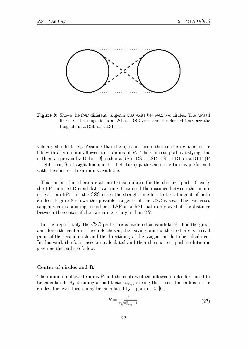
2.8 Landing 2 METHODS
Figure 8: Shows the four di�erent tangents that exist between two ir les. The dottedlines are the tangents in a LSL or RSR ase and the dashed lines are thetangents in a RSL or a LSR ase.velo ity should be χt. Assume that the a/ an turn either to the right or to theleft with a minimum allowed turn radius of R. The shortest path satisfying thisis then, as proven by Dubin [2℄, either a RSR, RSL, LSR, LSL, LRL or a RLR (R- right turn, S -straight line and L - Left turn) path where the turn is performedwith the shortest turn radius available.This means that there are at most 6 andidates for the shortest path. Clearlythe LRL and RLR andidates are only feasible if the distan e between the pointsis less than 6R. For the CSC ases the straight line has to be a tangent of both ir les. Figure 8 shows the possible tangents of the CSC ases. The two rosstangents orresponding to either a LSR or a RSL path only exist if the distan ebetween the enter of the two ir le is larger than 2R.In this report only the CSC paths are onsidered as andidates. For the guid-an e logi the enter of the ir le hosen, the leaving point of the �rst ir le, arrivalpoint of the se ond ir le and the dire tion χ of the tangent needs to be al ulated.In this work the four ases are al ulated and then the shortest paths solution isgiven as the path to follow.Center of ir les and RThe minimum allowed radius R and the entres of the allowed ir les �rst need tobe al ulated. By de iding a load fa tor nzref during the turns, the radius of the ir les, for level turns, may be al ulated by equation 27 [6℄,R = v2
g√
n2zref
−1. (27)22

2.8 Landing 2 METHODSThe entres of the left and right ir les, with radius R, whi h is a tangent to apoint (x, y) with velo ity v and dire tion χ an be al ulated by equation 28,OR = (x+R sin(χ), y +R cos(χ)) for a right ir le andOL = (x−R sin(χ), y +R cos(χ)) for a left ir le. (28)Using equations 27 and 28, both left and right ir les are known for both theinitial point and �nal point.LSL and RSR Figure 9 shows the path to follow for a LSL ase. Sin e, theradius of the two ir les are the same it follows that the path is parallel with theline onne ting the two entres of the ir les. In Figure 9, x1, y1 is a oordinatesystem with origin at (xoa, yoa) and orientated along the x1-axis towards the enterof the �nal ir le. The rotation of the x1-axis from the xe-axis an be al ulatedby equation 29.
χ1 =
arctan(
| dydx|)
, if dx ≥ 0, dy ≥ 0
2π − arctan(
| dydx|)
, if dx ≥ 0, dy < 0
π − arctan(
| dydx|)
, if dx < 0, dy ≥ 0
π + arctan(
| dydx|)
, if dx < 0, dy < 0
(29)Sin e the radius of the ir les are equal the dire tion of the path is the same asthe dire tion of the x1-axis and thus, χs = χ1.The position of the points for leaving the �rst ir le and arriving at the �nal ir le are, given in the lo al oordinate system, (xL,1, yL,1) and (xA,1, yA,1). Thevalues of these are given in equation 30 for the LSL ase.
xL,1 = 0yL,1 = −RxA,1 = DyA,1 = −R
(30)Transforming the lo al oordinates into the earth �x oordinate system one getsthat (xL, yL) and (xA, yA) are:xL = xL,1 cos(χ1)− yL,1 sin(χ1) + xoa
yL = xL,1 sin(χ1) + yL,1 cos(χ1) + yoaxA = xA,1 cos(χ1)− yA,1 sin(χ1) + xoa
yA = xA,1 sin(χ1) + yA,1 cos(χ1) + yoa
(31)For the RSR ase the point and dire tion an be al ulated by setting yL,1 = Rand yA,1 = R in equation 30 and then use equations 29 and 31.23

2.8 Landing 2 METHODS
(xoa
,yoa
)
(xob
,yob
)
xe
dx
dy(x
L,y
L)
(xA,y
A)
χ1
χsD
y1
x1
Figure 9: LSL illustrated with some points and angles. The radius of the ir les are R.xe indi ates the dire tion of the x-axis of the earth �xed oordinate system.LSR and RSL First the LSR ase will be dis ussed and then the hanges neededfor the RSL path are explained. An illustration of the LSR ase is presented in theFigure 10. The straight line path in this ase is a ross tangent from the initial tothe �nal ir le. As in the LSL ase a lo al oordinate system is introdu ed whi hhas its origin in the enter of the �rst ir le and has its x-axis oriented towardsthe enter of the �nal ir le (in Figure 10 this is (x1, y1)). The orientation withrespe t to the earth system is given by χ1 whi h an be al ulated with equation 32,
χ1 =
arctan(
ybo−yaoxbo−xao
)
, if xbo − xao ≥ 0
π − arctan(
ybo−yaoxbo−xao
)
, if xbo − xao < 0.(32)Given that the radius of the two ir les are both R. The triangles oa, E, L and
ob, E, L in Figure 10 are uniform. This an be used to al ulate the leaving andarrival points in the lo al oordinates by equation 33,D =
√
(ybo − yao)2 − (xbo − xao)2
xE,1 = D/2
yL,1 =−RxE,1
√
x2E,1 − R2
xL,1 =√
R2 − y2L,1
yA,1 =R
D−xE,1
√
(D − xE,1)2 − R2
xA,1 = −√
R2 − y2A,1 +D.
(33)24

2.8 Landing 2 METHODS
xe
y1
x1
χ1
χs
(xL,y
L)
(xA,y
A)
(xoa
,yoa
)
(xob
,yob
)
E
Figure 10: LSR illustrated with some points and angles. The radius of the ir les are R.xe indi ates the dire tion of the x-axis of the earth �xed oordinate system.These an then be transformed by equation 34 into earth �xed oordinates,
xL = xL,1 cos(χ1)− yL,1 sin(χ1) + xoa
yL = xL,1 sin(χ1) + yL,1 cos(χ1) + yoaxA = xA,1 cos(χ1)− yA,1 sin(χ1) + xoa
yA = xA,1 sin(χ1) + yA,1 cos(χ1) + yoa.
(34)Let dx = xA−xL and dy = yA−yL the ourse angle χs is then given by equation 35,χs =
arctan(
| dydx|)
, if dx ≥ 0, dy ≥ 0
2π − arctan(
| dydx|)
, if dx ≥ 0, dy < 0
π − arctan(
| dydx|)
, if dx < 0, dy ≥ 0
π + arctan(
| dydx|)
, if dx < 0, dy < 0.
(35)For the RSL ase, the signs of yL,1 and yA,1 in equation 33 are hanged and thenequations 34 and 35 will give the leaving point, arrival point and the ourse angleof the path.2.8.5 Landing pro edureGiven the initial position of the a/ (xi, yi, hi), with ourse angle, χi, velo ity v,the tou h down point at (xf , yf , zf ) with ourse angle χf , the des ent angle γrefand the des ent angle of atta k αref . The path and ontrol logi during the landingis as follows:• Cal ulate the point from whi h to start the des ent (xd, yd, hi) with dire tionχf by equation 13. 25

2.8 Landing 2 METHODS• Cal ulate a �yable path from (xi, yi, hi) with dire tion χi to (xd, yd, hi) withdire tion χf using the method des ribed in Se tion 2.8.4.For the ontrol in the xe, ye-plane the guidan e logi presented in Se tion 2.8.2 isapplied with a onstraints that ϕref ∈ [− arccos(nzref −1), arccos(nzref −1)] ex eptduring the des ent part where the limit is ϕref ∈ [−20◦, 20◦].The altitude of the a/ is ontrolled by altitude ontrol des ribed earlier. Thevalues of href(x, y), γa(x, y) and the limits of γpm during the di�erent stages aregiven in Table 1.
href(x, y) γa γpm ∈First turn hi 0 [−3◦, 3◦]The straight hi 0 [−3◦, 3◦]Final turn hi 0 [−5◦, 0◦]Des ent |D tan(γref)| γref [−5◦, 0◦]Table 1: Values in the di�erent stages of the landing. D is the distan e from the urrentposition to the tou h down point.When the altitude is below 300m. The landing gear is pulled out and the on-trol towards αref is a tivated. Then when the altitude is below 10m the altitude ontrol is swit hed o� and γ is ontrolled towards the user set γref . Then whenthe distan e to the ground is less than 5m the guidan e law is swit hed o� andthe pilot model ontrols towards ϕref = 0◦.When the wheels of the a/ tou hes ground the pilot brakes and puts the throttlein its minimum position. Then when the speed of the a/ is small the blo k is onsidered done and the mission is ompleted.
26

3 RESULTS3 Results3.1 Test missionIn this theses work an test mission onsisting of 16 blo ks was designed by SAAB.This is not one of the missions used at SAAB during development.The landing blo k is divided in to two part alled 16a and 16b. An birds eyeoverview of the mission is presented in Figure 11 where the start of ea h blo k ismarked with a ir le and Figure 12 shows the altitude during the mission.
−8 −7 −6 −5 −4 −3 −2 −1 0 1
−6
−5
−4
−3
−2
−1
0
x 104
y e [m]
1
2
3
4
5
6
7
8
9
10
11
12
13
14
16a
15
16b
Figure 11: Overview of the test mis-sion. The number indi- ates the a/ position atthe start of the orrespond-ing blo k.0 200 400 600 800 1000 1200 1400 1600
0
2000
4000
6000
8000
10000
12000
h [m
]
Figure 12: Altitude during the mis-sion. The dotted lines in-di ate the start of a newblo k and the last dot-ted line indi ates that thelanding gear is pulled out.The a/ is set up with two external loads and starts from an airport with analtitude of 54m above sea-level. Its position is at the origin of the earth �xed oordinate system and is fa ing an ourse angle of 290◦. A short des ription ofea h blo k are presented below:1 Take-O�. Control toward θref = 10. The blo k is onsider as done when thealtitude is above 100m from sea-level.2 This blo k is a onstant speed then a onstant Ma h number limb with aroll level out. Climb to 5000m �rst with onstant speed of 195ms−1 and thenwith onstant Ma h number of 0.7. The load fa tor, nz, should be in [0.3, 6].3 Turn with nz,ref = 3 to χref = 200◦ and in rease Ma h number to 0.9.4 Climb to 11000m without roll and γref = 7◦. Ma h number kept at 0.9 withthrottle ontrol and nz ∈ [0.3, 6]. 27

3.1 Test mission 3 RESULTS5 Cruise with altitude ontrol to 11000m. nz should be in [0.7, 1.5]. The Ma hnumber is kept at 0.9 with throttle ontrol. This should be done for 50s.6 Combat simulation. Fly in a �gure 8 keeping the Ma h number at 0.9 givena onstant throttle position. χref = 200◦ and when the blo k is done �reexternal store 1. The �gure 8 �ying should be done for 300s.7 Turn with nz,ref = 2 to χref = 110◦ and ontrol Ma h number to 0.9 withthe throttle and ontrol the a/ to an altitude of 11000m.8 Cruise with a eleration. Control towards the altitude 11000m and in reaseMa h number to 1.2. The blo k is done when the Ma h number is rea hed.9 Des end with roll to 6000m. The des ent is done with γref = −30◦ andthrottle ontrol is used to try and keep the Ma h number to 1.2. nz shouldbe in [0.3, 6].10 Turn with nz,ref = 5 to χref = 300◦ and ontrol Ma h number to 1.2 withthe throttle and ontrol the a/ to an altitude of 6000m.11 Cruise with altitude ontrol to 6000m. nz should be in [0.7, 1.5]. The Ma hnumber is kept at 1.2 with throttle ontrol. This should be done for 60s.12 Combat simulation. Fly in a �gure 8 with nz,ref = 4 given a onstant throttleposition. χref = 300◦ and when the blo k is done �re external store 2. The�gure 8 �ying should be done until the Ma h number is below 0.6.13 Turn with nz,ref = 3 to χref = 20◦ and ontrol Ma h number to 0.6 with thethrottle and ontrol the a/ to an altitude of 6000m.14 Des ent to 1000m without a roll. Keep the Ma h number to 0.6 with thethrottle at its minimum position. Keep nz ∈ [0.3, 6].15 Cruise without altitude ontrol. The Ma h number is ontrolled to 0.5 withthrottle ontrol. This should be done for 50s.16 From given position tou h down at [0, 0, 54]m with dire tion χf = 20◦. Thereferen e altitude is href = 1000m and the des ent should be done withγref = −2.8◦ and αref = 12◦. In 16a the Ma h number is kept at 0.5. The Lfor the guidan e law is set to 600m.In this test mission many of the blo ks are of the same type with only slightdi�eren es. For this reason the results will be presented in the same order as thetype of blo ks are presented in the Methods se tion. In the ase where two blo ksprodu e similar results only one of the blo ks will be presented.
28

3.2 Take-o� 3 RESULTS3.2 Take-o�The take-o� starts at the initial position and as an be seen in Figure 13, θ = 10◦is rea hed and held. Then when the altitude is 100m at the time 33.9s the blo kis done and the the landing gear is retra ted.
0 5 10 15 20 25 30
0
1
2
3
4
5
6
7
8
9
10
θ [d
eg]
Figure 13: Pit h angle during blo k number 1.3.3 Climb3.3.1 Without rollOnly blo k 4 is a limb without a roll ending. In Figure 14 the altitude during theblo k is presented. The value of γ and its referen e value of 7◦, are presented inFigure 15.
200 220 240 260 280 300 320 340 360 3805000
6000
7000
8000
9000
10000
11000
altit
ude
[m]
AltitudeDesired altitudeFigure 14: The altitude and the ref-eren e in altitude duringblo k number 4. 200 220 240 260 280 300 320 340 360 380
−6
−4
−2
0
2
4
6
8
γ [d
eg]
Climb angleDesired climb angleFigure 15: Climb angle during blo knumber 4.
29
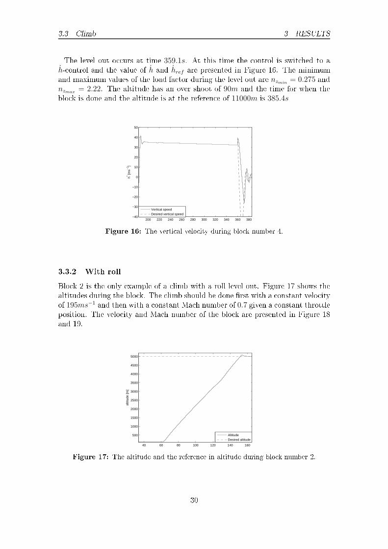
3.3 Climb 3 RESULTSThe level out o urs at time 359.1s. At this time the ontrol is swit hed to ah- ontrol and the value of h and href are presented in Figure 16. The minimumand maximum values of the load fa tor during the level out are nzmin
= 0.275 andnzmax
= 2.22. The altitude has an over shoot of 90m and the time for when theblo k is done and the altitude is at the referen e of 11000m is 385.4s
200 220 240 260 280 300 320 340 360 380−40
−30
−20
−10
0
10
20
30
40
50h* [m
s−1 ]
Vertical speedDesired vertical speedFigure 16: The verti al velo ity during blo k number 4.
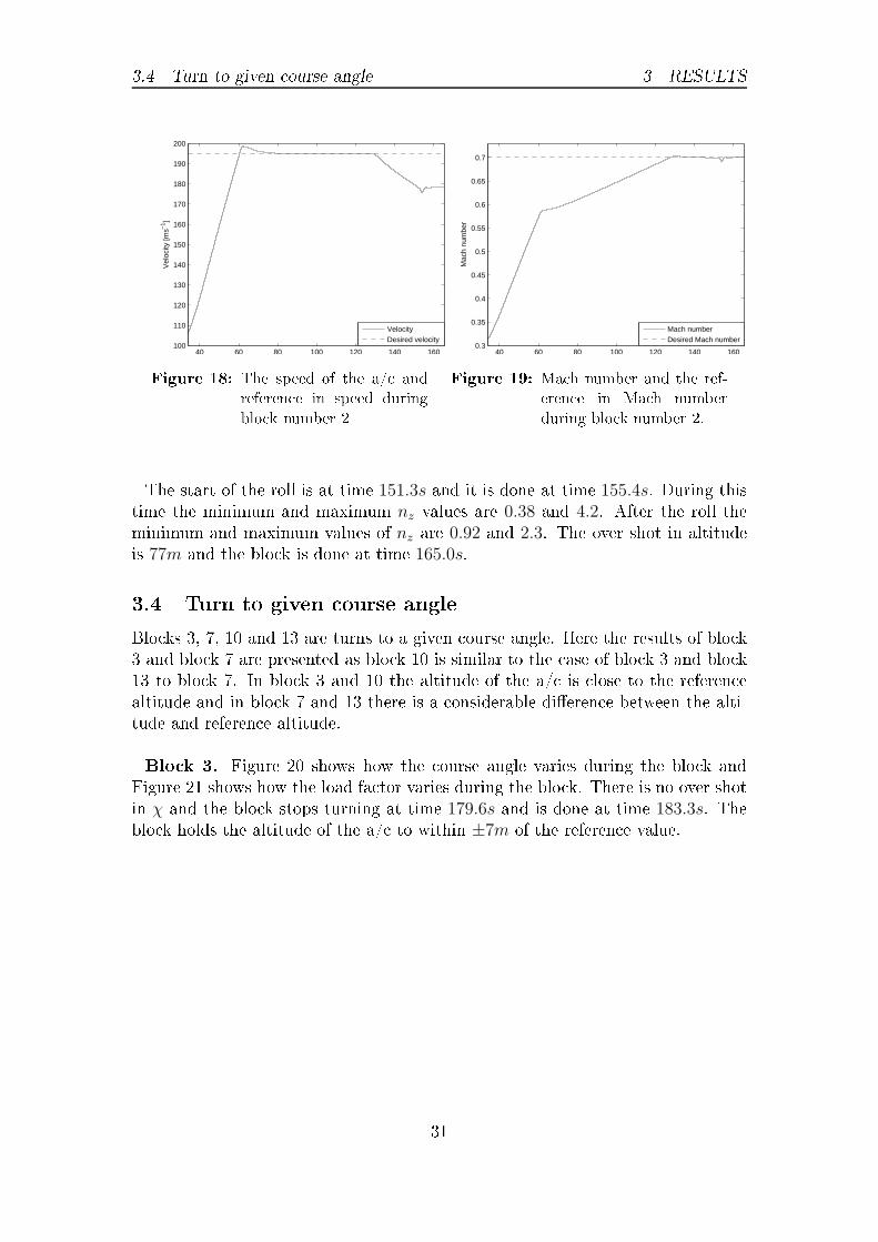
3.3.2 With rollBlo k 2 is the only example of a limb with a roll level out. Figure 17 shows thealtitudes during the blo k. The limb should be done �rst with a onstant velo ityof 195ms−1 and then with a onstant Ma h number of 0.7 given a onstant throttleposition. The velo ity and Ma h number of the blo k are presented in Figure 18and 19.
40 60 80 100 120 140 160
500
1000
1500
2000
2500
3000
3500
4000
4500
5000
altit
ude
[m]
AltitudeDesired altitudeFigure 17: The altitude and the referen e in altitude during blo k number 2.
30
3.4 Turn to given ourse angle 3 RESULTS
40 60 80 100 120 140 160100
110
120
130
140
150
160
170
180
190
200
Vel
ocity
[ms−
1 ]
VelocityDesired velocityFigure 18: The speed of the a/ andreferen e in speed duringblo k number 2 40 60 80 100 120 140 160
0.3
0.35
0.4
0.45
0.5
0.55
0.6
0.65
0.7
Mac
h nu
mbe
r
Mach numberDesired Mach numberFigure 19: Ma h number and the ref-eren e in Ma h numberduring blo k number 2.The start of the roll is at time 151.3s and it is done at time 155.4s. During thistime the minimum and maximum nz values are 0.38 and 4.2. After the roll theminimum and maximum values of nz are 0.92 and 2.3. The over shot in altitudeis 77m and the blo k is done at time 165.0s.3.4 Turn to given ourse angleBlo ks 3, 7, 10 and 13 are turns to a given ourse angle. Here the results of blo k3 and blo k 7 are presented as blo k 10 is similar to the ase of blo k 3 and blo k13 to blo k 7. In blo k 3 and 10 the altitude of the a/ is lose to the referen ealtitude and in blo k 7 and 13 there is a onsiderable di�eren e between the alti-tude and referen e altitude.Blo k 3. Figure 20 shows how the ourse angle varies during the blo k andFigure 21 shows how the load fa tor varies during the blo k. There is no over shotin χ and the blo k stops turning at time 179.6s and is done at time 183.3s. Theblo k holds the altitude of the a/ to within ±7m of the referen e value.
31

3.5 Cruise 3 RESULTS
166 168 170 172 174 176 178 180 182
160
180
200
220
240
260
280
300
320
340
360
χ [d
eg]
Course angleDesired course angle
Figure 20: Course angle during blo knumber 3 166 168 170 172 174 176 178 180 1820
0.5
1
1.5
2
2.5
3
3.5
4
n z
nz
Desired nzFigure 21: The load fa tor duringblo k number 3.Blo k 7. The progress of the ourse angle during the blo k is presented in Fig-ure 22, the altitude in Figure 23 and the load fa tor in Figure 24. The blo k stopsturning at time 770.7s and is done at time 772.7s from the start of the mission.
740 745 750 755 760 765 770100
150
200
250
χ [d
eg]
Course angleDesired course angle
Figure 22: Course angle during blo k number 7.3.5 Cruise3.5.1 Altitude holdBlo k 5, 8 and 11 are ruises with altitude hold. The results in all of them aresimilar and so blo k 8 is presented here as it also ontains an a eleration. Thealtitude of the blo k is presented in Figure 25 and the Ma h number is presentedin Figure 26. The blo k is done when the Ma h number rea hes 1.2.
32

3.6 Combat simulation 3 RESULTS
740 745 750 755 760 765 7701.04
1.05
1.06
1.07
1.08
1.09
1.1
1.11x 10
4
altit
ude
[m]
AltitudeDesired altitude
Figure 23: The altitude and the ref-eren e in altitude duringblo k number 7. 740 745 750 755 760 765 770−1
0
1
2
3
4
5
n z
n
z
Desired nz
Figure 24: The value of the load fa torduring blo k number 7.
775 780 785 790 795 800 805 810 8151.0995
1.1
1.1005
1.101
1.1015x 10
4
altit
ude
[m]
AltitudeDesired altitude
Figure 25: The altitude and the ref-eren e in altitude duringblo k number 8. 775 780 785 790 795 800 805 810 815
0.9
0.95
1
1.05
1.1
1.15
1.2
Mac
h nu
mbe
r
Mach numberDesired Mach numberFigure 26: Ma h number during blo knumber 8.
3.5.2 Gamma holdOnly blo k 15 is an ruise where the pilot ontrols the a/ to hold γ to 0◦. Thealtitude at the start of the blo k is 997m and during the blo k the altitude �rst limbs to 1000m and the drops and stabilizes at 994m. The blo k also ontrols theMa h number from 0.6 to the desired Ma h number of 0.5 and holds this Ma hnumber until the blo k is done.3.6 Combat simulationThere are two ombat simulation blo ks in the mission. The �rst simulation isin blo k 6. The Ma h number during the blo k is almost onstant but in reases33

3.6 Combat simulation 3 RESULTSduring the swit hes of the turn dire tion by 0.2. The ourse angle is presented inFigure 27 and the variations of the altitude is presented in Figure 28.
450 500 550 600 650 7000
50
100
150
200
250
300
350
χ [d
eg]
Course angle
Course angle 200°
Figure 27: Course angle during blo knumber 6. 450 500 550 600 650 7001.04
1.05
1.06
1.07
1.08
1.09
1.1
1.11
1.12
1.13
1.14
1.15x 10
4
altit
ude
[m]
AltitudeDesired altitude
Figure 28: The altitude and the ref-eren e in altitude duringblo k number 6.Blo k 12 is the se ond ombat simulation. In this blo k the altitude in reaseswith 89m during the blo k. The load fa tor that is to be ontrolled towards 4 ispresented in Figure 29 and the Ma h number that is the limit of when the blo kshould be done is presented in Figure 30.
960 970 980 990 1000 1010 1020 1030 1040 1050 10600
1
2
3
4
5
6
n z
n
z
Desired nz
Figure 29: The value of the load fa torduring blo k number 12. 960 970 980 990 1000 1010 1020 1030 1040 1050 10600.5
0.6
0.7
0.8
0.9
1
1.1
1.2
Mac
h nu
mbe
r
Figure 30: The Ma h number and thereferen e in Ma h numberduring blo k number 12.34
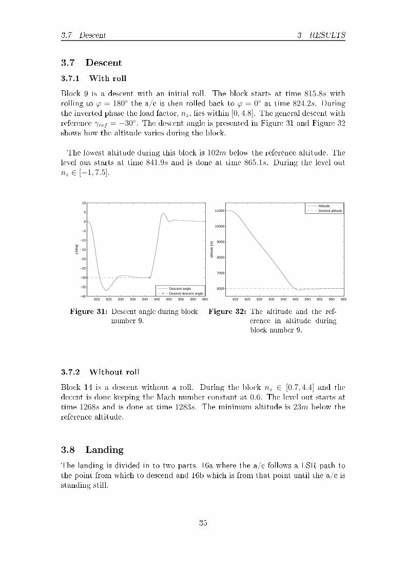
3.7 Des ent 3 RESULTS3.7 Des ent3.7.1 With rollBlo k 9 is a des ent with an initial roll. The blo k starts at time 815.8s withrolling to ϕ = 180◦ the a/ is then rolled ba k to ϕ = 0◦ at time 824.2s. Duringthe inverted phase the load fa tor, nz, lies within [0, 4.8]. The general des ent withreferen e γref = −30◦. The des ent angle is presented in Figure 31 and Figure 32shows how the altitude varies during the blo k.The lowest altitude during this blo k is 102m below the referen e altitude. Thelevel out starts at time 841.9s and is done at time 865.1s. During the level outnz ∈ [−1, 7.5].
820 825 830 835 840 845 850 855 860 865−40
−35
−30
−25
−20
−15
−10
−5
0
5
10
γ [d
eg]
Descent angleDesired descent angleFigure 31: Des ent angle during blo knumber 9. 820 825 830 835 840 845 850 855 860 865
6000
7000
8000
9000
10000
11000al
titud
e [m
]
AltitudeDesired altitude
Figure 32: The altitude and the ref-eren e in altitude duringblo k number 9.3.7.2 Without rollBlo k 14 is a des ent without a roll. During the blo k nz ∈ [0.7, 4.4] and thede ent is done keeping the Ma h number onstant at 0.6. The level out starts attime 1268s and is done at time 1283s. The minimum altitude is 23m below thereferen e altitude.3.8 LandingThe landing is divided in to two parts, 16a where the a/ follows a LSR path tothe point from whi h to des end and 16b whi h is from that point until the a/ isstanding still. 35

3.8 Landing 3 RESULTSDuring 16a, the referen e path and a/ position when the a/ follows the leftturns path is presented in Figure 33. The swit h to follow the straight line is attime τ1 = 1364.3s, to follow the �nal right turn starts at time τ2 = 1445.4s andthen the des ent ontrol starts at time τ3 = 1469.9s. The referen e and the valueof the roll angle are presented in Figure 34 and in Figure 35 the altitude of thea/ during the initial part of the blo k is shown.
−1.6 −1.55 −1.5 −1.45 −1.4 −1.35 −1.3 −1.25
x 104
−2.55
−2.5
−2.45
−2.4
−2.35
−2.3
−2.25
x 104
xe [m]
y e [m]
p1
p2
p3
Flight pathDesired path
Figure 33: Initial turn in blo k number 16a.
1360 1380 1400 1420 1440 1460 1480
−60
−40
−20
0
20
40
60
φ [m
]
τ1
τ2
τ3
Roll angleDesired roll angleFigure 34: Roll angle during blo knumber 16a. 1360 1380 1400 1420 1440 1460 1480
900
920
940
960
980
1000
1020
altit
ude
[m]
τ1
τ2
τ3
AltitudeDesired altitudeFigure 35: Altitude during blo knumber 16a.The value and referen e value of the roll angle during 16b are presented in Figure36. The error in ourse angle denoted χerr in Se tion 2.8.2 is shown in Figure 37,it should be noted that the errors are very small. The velo ity of the a/ is shownin Figure 38. The altitude of the a/ and referen e in altitude is shown in Figure39. In Figures 40 and 41, γ and α are shown. γ is shown for the whole of 16b and
α is shown from about 10s before the landing gear is pulled out.36
3.8 Landing 3 RESULTS
1500 1520 1540 1560 1580 1600 1620 1640 1660−5
−4
−3
−2
−1
0
1
2
3
4
5
φ [m
]
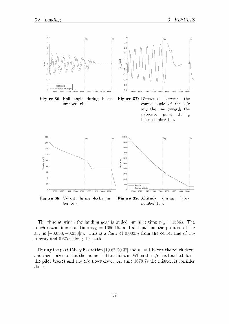
τldg
τtd
Roll angleDesired roll angleFigure 36: Roll angle during blo knumber 16b. 1500 1520 1540 1560 1580 1600 1620 1640 1660
−0.5
−0.4
−0.3
−0.2
−0.1
0
0.1
0.2
0.3
0.4
0.5
χ erro
r [deg
]
τldg
τtd
Figure 37: Di�eren e between the ourse angle of the a/ and the line towards thereferen e point duringblo k number 16b.
1500 1520 1540 1560 1580 1600 1620 1640 16600
20
40
60
80
100
120
140
160
180 τldg
τtd
Vel
ocity
[ms−
1 ]
Figure 38: Velo ity during blo k num-ber 16b. 1500 1520 1540 1560 1580 1600 1620 1640 16600
100
200
300
400
500
600
700
800
900
1000
altit
ude
[m]
τldg
τtd
AltitudeDesired altitudeFigure 39: Altitude during blo knumber 16b.The time at whi h the landing gear is pulled out is at time τldg = 1586s. Thetou h down time is at time τTD = 1666.15s and at that time the position of thea/ is [−0.633,−0.233]m. This is a fault of 0.002m from the enter line of therunway and 0.67m along the path.During the part 16b, χ lies within [19.6◦, 20.3◦] and nz ≈ 1 before the tou h downand then spikes to 3 at the moment of tou hdown. When the a/ has tou hed downthe pilot brakes and the a/ slows down. At time 1679.7s the mission is onsiderdone.
37

4 DISCUSSION
1500 1520 1540 1560 1580 1600 1620 1640 1660−4
−3.5
−3
−2.5
−2
−1.5
−1
−0.5
0
0.5
1
γ [d
eg]
τldg
τtd
γDesired γFigure 40: Des ent angle during blo knumber 16b. 1580 1590 1600 1610 1620 1630 1640 1650 1660 1670
0
2
4
6
8
10
12
14
α [d
eg]
τldg
τtd
Angle of attackDesired angle of attackFigure 41: Angle of atta k blo k num-ber 16b.4 Dis ussion4.1 Take-o�The main part of the take o� is done with the pilot model that was designed bySAAB. The ondition for when the blo k is done works as it should and at theswit h to the next blo k the a/ starts pulling in the landing gear as it should.4.2 Climb4.2.1 Without rollFor the general limb there is a fairly fast response to hold the referen e in γ. Dur-ing the level out nz drops below the soft onstraints of 0.3 to its minimum valueof 0.27. This is only during a short period of time when trying to hold nz = 0.3during the level out. The time it takes to level out is 26.3s. The fa t that thea/ �nds its intended height and holds the lowest allowed nz during the level out,shows that the blo k works in the intended way.4.2.2 With rollIn the �rst part of blo k 2 the a/ does not start to limb right away. The reasonfor this is that the velo ity of the a/ is below the 195ms−1 that the limb should�rst be done with. Then when the velo ity rea hes 195ms−1 the limb starts asintended and when the Ma h number is high enough the limb is done with on-stant Ma h number as it should.The level out starts at time 151.3s. The a/ is then rolled around, it is whenthe a/ rolls that the minimum nz of the roll o urs. The a/ then pulls high38

4.3 Turn to given ourse angle 4 DISCUSSIONload fa tor to slow the a/ down in the verti al dire tion and then rolls ba k when|h| < 2ms−1. This o urs 4.1s after the start of the roll. Then there are minor orre tions in order to level out at the right altitude and the whole level out isdone after a total of 13.7s.During the whole level out the soft onstraints on the load fa tor are held.4.3 Turn to given ourse angleAs dis ussed in the result se tion there are two di�erent ases for the turn. Thereason for the ases are that if the altitude is lose to the referen e altitude thea/ an use all allowed nz to turn the a/ around. As seen for blo k 3 in Figures20 and 21, χ hanges �rst slowly and when the a/ has built up some nz the turnrate speeds up.The other ase is when the di�eren e between the referen e and the urrent alti-tude is large, as in the ase of blo k 7, the a/ annot turn using all nz as in reasingthe altitude introdu es extra load fa tor and the pilot model only allows a ertainamount in total.In blo k 3 the level out time is 3.7s and in blo k 7 it is 2.0s. One reason for thedi�eren e in time to level out is that in blo k 3 the referen e in nz during the turnis 3 and in blo k 7 it is 2.4.4 Cruise4.4.1 Altitude holdIn blo k 8 the altitude is held within 15m of its referen e value and the a elerationis fairly linear towards its �nal value of Ma h 1.2. It may also be seen in this blo kthat the �nal onstraint of the a/ having a Ma h number above a given numberworks.4.4.2 Gamma holdAs an be seen in the result se tion the γ hold fun tion works as ould be expe ted.The blo k also de reases the power ommanded to the engine so that the referen ein Ma h number is rea hed.4.5 Combat simulationDuring the ombat simulation in blo k 6, the altitude during ea h of the turns inthe �gure eight, de reases with about 150m. The result is a eptable onsideringthe type of manoeuvring that is being made and that only open loop altitude39

4.6 Des ent 4 DISCUSSION ontrol is applied. When the turn dire tion hanges the Ma h number of the a/ in reases with 0.2 and is then ontrolled ba k to the referen e value during the turn.It an be seen from Figure 27 that the turns are made around the desired 200◦ line.In blo k 12, the model keeps the load fa tor to the desired value during the turnsbut as an be expe ted the value drops momentarily to 1 during the swit hes.4.6 Des ent4.6.1 With rollThe initial roll and general des ent in blo k 9 behaves as expe ted. The Ma hnumber during the blo k in reases with the falling altitude and when the level outstarts it is 1.35. In this high speed the level out ontrol did not manage to keepthe load fa tor inside the given onstraints. During a short period of time the loadfa tor is in reased to 7.5.4.6.2 Without rollThe level out without roll is done in the way that was intended. The load fa toris kept in side the onstraints both in the start of the des ent and in the end ofthe des ent. The time to level out is 15s.4.7 LandingIn general the landing is done as expe ted. The path al ulated is �yable and thetou hdown point is only 0.67m away from the intended tou hdown point. Mostof the distan e is along the runway and onsidering the ontrol is swit hed o� ashort period of time before the tou h down this must be onsidered a good result.4.7.1 Guidan e lawThe nonlinear guidan e logi gives good results in guiding the a/ to the desiredpath.4.7.2 α and γ ontrolThe des ent angle ontrol during the landing phase is good when the roll angle issmall. The fa t that the pilot model of [1℄ is not so good in ontrol of γ when theroll angle is big is a known. When the roll angle is small during the des ent partthe des ent angle is ontrolled as wanted and expe ted.The ontrol of the angle of atta k is an open loop ontrol. This means that erroris to be expe ted. From the result one an see a steady error of 0.8◦. Over all the40

4.8 Full mission 4 DISCUSSIONsteady error is relatively small onsidering an open loop ontrol law.4.8 Full missionOver all, a full mission has been simulated with a number of di�erent blo ks. Ithas been shown through the test mission that the blo ks may be onne ted inseries and so the system an be used to set up any mission that uses the blo ksthat have been designed.One of the main bene�ts for SAAB from this work is that simulating this testmission in a desktop environment is 17 times faster than it would be to simulateit in �ight simulator with a real pilot.
41

5 CONCLUSIONS5 Con lusionsThis thesis des ribes how a system, for high level input in order to simulate a fullmission �ight for JAS 39 Gripen, was reated and how it works. The mission isset up by a series of task to be performed. These tasks then link to di�erent pilotmodels that then ontrols the a/ to perform the given task and then move on tothe next task until the mission is omplete. A test mission ontaining all the taskswas simulated to show that the system works.For the limb and the des ent to a given altitude, the general limb/des ent wasdone with existing pilot models, the level out was done by ontrol on the verti alvelo ity with a PD- ontroller on the altitude error. The results was that the a/ levels out at the given altitude.Turn to given ourse angle. In the ase where the turn starts at level �ight theturn is performed without any problems. If on the other hand at the start ofthe task the a/ is not in level �ight there is a time delay before the turn starts.One of the reasons for this is that the turn is made by ontrolling on the load fa tor.Landing at spe i�ed point. First a path onsisting of, a CSC path and a des entpath, from the urrent position to the �nal position was al ulated. Then theguidan e logi from [5℄ was used for guiding the a/ in the x-y- plane and a pro-portional ontrol was used to ontrol the altitude. Over all the task is performedwith very good end results. Due to the design of the pilot models of [1℄ the blo khas some problems with simultaneous ontrol on both ϕ and γ.
42

REFERENCES REFERENCESReferen es[1℄ Per Ajdén and Carl Ba klund. Pilotmodeller till �ygmekanisk simulator för jas39 gripen. Master's thesis, Linköping University, Me hani s, 2010.[2℄ L. E. Dubins. On urves of minimal length with a onstraint on average urva-ture, and with pres ribed initial and terminal positions and tangents. Ameri anJournal of Mathemati s, 79(3):pp. 497�516, 1957.[3℄ G. Du ard, K. C. Kulling, and H.P. Geering. A simple and adaptive on-linepath planning system for a uav. In Control Automation, 2007. MED '07.Mediterranean Conferen e on, pages 1�6, 2007.[4℄ Robert K. H�ey. Appli ation of task-pilot-vehi le (tpv) models in �ight sim-ulation. In Presented at the Amari an Heli opter So iety 66th Annual Forum,2010.[5℄ Sanghyuk Park, John Desyst, and Jonathan P. How. A new nonlinear guid-an e logi for traje tory tra king. In AIAA Guidan e, Navigation, ControlConferen e and Exhibit, pages 16�19, 2004.[6℄ E. Torenbeek and H. Wittenberg. Flight Physi s. Springer, 2009. ISBN 978-1-4020-8663-2.
43


TRITA-MAT-E 2013:53 ISRN-KTH/MAT/E—13/53-SE
www.kth.se


![Franck Pigeonneau 2018 - TherMatHT€¦ · Fluid dynamics close to a contact line. ... J. D. van der Waals (1837-1923). F [ϕ ] = Z Ω Ψ(ϕ)+ k 2 || ∇ ϕ || 2 dV. (4) Ψ(ϕ) is](https://static.fdocuments.in/doc/165x107/605eedcd76a1c427d74db860/franck-pigeonneau-2018-thermatht-fluid-dynamics-close-to-a-contact-line-j.jpg)