PILANI ELECTRON TUBES & DEVICES PVT · The device envelope provides only limited protection and...
7
Pilani Electron Tubes & Devices Pvt. Ltd. Patiala Road, Sangrur, PB, 148001, India Phone: +91-9815309603 Email: [email protected] Website: www.pilanielectron.com Version 1.3, February 2018 PET1606J2F Water Cooled Triode For Industrial RF Heating Drop in equivalent of BW1606J2F Output Power: 30 kW Anode voltage: 10 kV max Anode dissipation: 15 kW max Frequency up to 30 MHz Manufactured in India, in a world-class facility equipped with high quality machinery, materials and components sourced from reputed suppliers in America, Europe and Japan. Fifty-two weeks warranty against manufacturing defects irrespective of the number of hours of operation.
Transcript of PILANI ELECTRON TUBES & DEVICES PVT · The device envelope provides only limited protection and...
Pilani Electron Tubes & Devices Pvt. Ltd. Patiala Road, Sangrur, PB, 148001, India
Phone: +91-9815309603 Email: [email protected]
Website: www.pilanielectron.com Version 1.3, February 2018
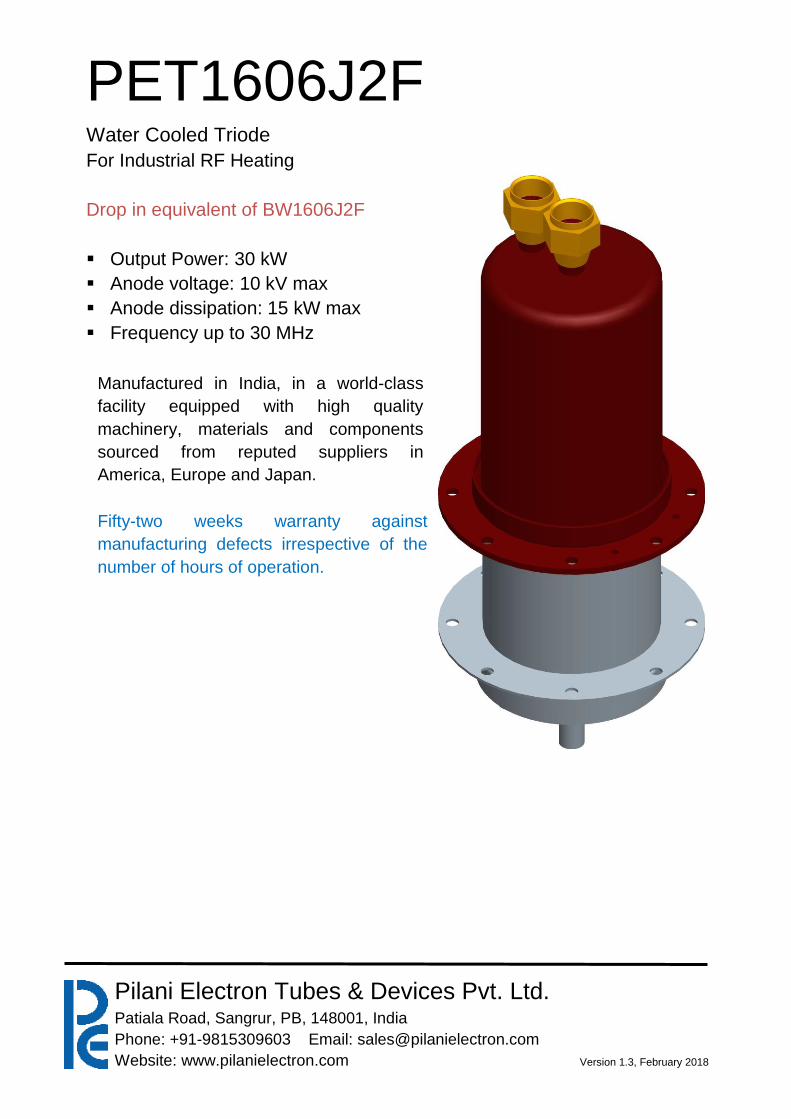
PET1606J2F Water Cooled Triode
For Industrial RF Heating
Drop in equivalent of BW1606J2F
Output Power: 30 kW
Anode voltage: 10 kV max
Anode dissipation: 15 kW max
Frequency up to 30 MHz
Manufactured in India, in a world-class
facility equipped with high quality
machinery, materials and components
sourced from reputed suppliers in
America, Europe and Japan.
Fifty-two weeks warranty against
manufacturing defects irrespective of the
number of hours of operation.
PET1606J2F
Pilani Electron Tubes & Devices Pvt. Ltd., Patiala Road, Sangrur, PB, 148001, India
Phone: +91-9815309603 Email: [email protected]
Website: www.pilanielectron.com Version 1.3, February 2018
Page 2
PET1606J2F is a water cooled power triodes of coaxial ceramic-metal construction. It is intended primarily for industrial R.F. heating machines. It comes with an integral water jacket.
Electrical Characteristics Filament . . . . . . . . . Thoriated tungsten Filament voltage (see note 1) . . . . . . . 6.6 Volts Filament Current . . . . . . . . 100 Amps Filament cold resistance . . . . . . . 8.0 mΩ Peak usable cathode current . . . . . . . 25 Amp Perveance . . . . . . . . . 4.0 mA/V3/2 Amplification factor (Va = 2.25 kV, la = 1.0 A) . . . . . 24 Mutual conductance (Va = 2.25 kV, la = 1.0 A). . . . . . 38 mA/V Inter-electrode capacitances: Grid to anode . . . . . . . . . 35 pF Grid to filament . . . . . . . . . 67 pF Anode to filament . . . . . . . . 2.0 pF
Mechanical Characteristics Overall dimensions . . . . . . . . See outline drawing Net weight: . . . . . . . . . 3.3 kg approx Mounting position . . . . . . . Vertical, either way up
Accessories Water coupling supplied with PET1606J2F . . . . PA323A Thermal fuse, available for PET1606J2F . . . . . PA85E Cathode Connector . . . . . . . PA830 For frequencies above 2MHz, PA830 should be used in conjunction with a strip connection to provide a low inductance cathode return.
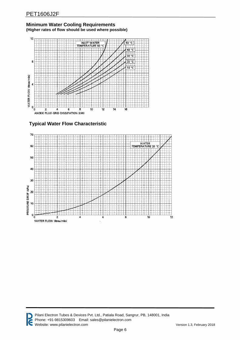
Cooling PET1606J2F has an integral water jacket. Minimum water cooling requirements are shown on page 7 higher rates of flow should be used where possible. The water pressure in the jacket must not exceed 6 atmospheres. A thermal fuse, part number PA85E (melting point 103 ⁰C), is available for PET1606J2F to give protection against anode overheating. Two fuses should be used for maximum protection, screwed into the holes indicated on the anode mounting plate (see page 8). The fuses should be connected by a non-conducting cord to a suitable switching device; a tension of about 1 pound (450 g) should be applied to the fuses via the cord. If the temperature exceeds the safe limit, one or both fuses will release and the fuse cord is pulled outwards; this should actuate the switching device and remove all electrical supplies to the tube. Replacement fuses can be supplied to order. Filament and Grid Seals The temperature of the filament and grid seals must not exceed 200 °C. A flow of air of 15ft³/min (0.43m³/min) directed onto the terminals via a 1-inch (25 mm approx) diameter nozzle from a distance of 6 inches before and during the application of any voltages is usually adequate for limiting the temperature of the seals.
Radio Frequency Oscillator For Industrial Service
(Class C conditions, one tube) Maximum Ratings (Absolute Values) Anode voltage . . . . . . . . . 10 kV max Anode current . . . . . . . . . 4.5 Amp max Anode dissipation (continuous or Intermittent service) . . . . 15 kW max Grid voltage (negative value) . . . . . . . –1.5 V max Off-load grid current . . . . . . . . 1.7 max Grid dissipation . . . . . . . . . 600 W max Frequency . . . . . . . . . 30 MHz max
PET1606J2F
Pilani Electron Tubes & Devices Pvt. Ltd., Patiala Road, Sangrur, PB, 148001, India
Phone: +91-9815309603 Email: [email protected]
Website: www.pilanielectron.com Version 1.3, February 2018
Page 3
Operating Conditions (At maximum anode current) Anode Voltage . . 9.5 9.0 8.0 7.0 6.0 kV Grid voltage . . –780 –740 –650 –575 –500 V From grid resistor . 867 822 625 553 500 Ω Peak r.f. grid drive voltage 1125 1085 1000 915 830 V Peak positive grid voltage 345 345 345 340 330 V Anode current . . 4.5 4.5 4.5 4.5 4.5 A Grid current . . 0.9 0.9 1.04 1.04 1.0 A Anode dissipation . 6.9 6.9 6.1 5.8 5.4 kW Grid dissipation . . 319 326 364 353 300 W Driving power . . 1000 1000 1040 952 830 W Feedback ratio (see note 2) 12.8 13.1 13.4 14.2 15.2 % Anode output power . 35.6 33.9 30.3 25.9 21.6 kW Anode efficiency . 83.7 83.1 83.00 81.6 80.0 % Oscillator output power (See note 3) . 34.6 32.9 29.2 24.9 20.8 kW Oscillator efficiency . 81.4 80.6 80.2 78.6 76.9 % Load resistance . 1088 1016 915 802 684 Ω
Operating Conditions (With reduced input power) Anode voltage . . 9.5 9.0 8.0 7.0 6.0 kV Grid voltage . . –780 –740 –650 –575 –50 V From grid resistor . 1560 1233 1083 958 714 Ω Peak r.f. grid drive voltage 1035 1000 905 830 760 V Peak positive grid voltage 255 260 255 255 260 V Anode current . . 3.0 3.0 3.0 3.0 3.0 A Grid current . . 0.5 0.6 0.6 0.6 0.7 A Anode dissipation . 4.5 4.1 4.0 3.6 3.2 kW Grid dissipation . . 130 145 144 156 180 W Driving power . . 530 566 513 507 524 W Feedback ratio (see note 2) 11.9 12 12.4 13 13.8 % Anode output power . 24.1 23.0 20.3 17.4 15.0 kW Anode efficiency . 84.4 84.8 83.4 83.0 82.6 % Oscillator output power (See note 3) . 23.6 22.4 19.8 16.9 14.5 kW Oscillator efficiency . 82.4 82.5 81.4 80.8 79.5 % Load resistance . 1570 1495 1315 1180 1008 Ω NOTES
1. The tube must be operated at the stated filament voltage. Fluctuation in filament voltage must not exceed ±5%. The filament may be switched on at its operating voltage and no surge limiting devices need be incorporated in the filament circuit. The voltage drop in the integral filament leads is less than 1% of the filament voltage.
2. The feedback ratio is defined as Vg (pk)/Va(pk) X 100 where Vg(pk) = peak r.f. grid voltage in
volts and Va(pk) = peak r.f. anode voltage in volts.
3. Oscillator output power = output power of tube to anode circuit and P drive = drive power fed back to grid circuit.
PET1606J2F
Pilani Electron Tubes & Devices Pvt. Ltd., Patiala Road, Sangrur, PB, 148001, India
Phone: +91-9815309603 Email: [email protected]
Website: www.pilanielectron.com Version 1.3, February 2018
Page 4
Health And Safety Hazards
PET electronic devices are safe to handle and operate, provided that the precautions stated are observed. PET does not accept responsibility for damage or injury resulting from the use of electronic devices it produces. Equipment manufacturers and users must ensure that adequate precautions are taken. Appropriate warning labels and notices must be provided on equipments incorporating PET devices and in operating manuals.
High voltage Equipment must be designed so that personnel cannot come into contact with high voltage circuits. All high voltage circuits and terminals must be enclosed and fail-safe interlock switches must be fitted to disconnect the primary power supply and discharge all high voltage capacitors and other stored energy before allowing access. Interlock switches must not be bypassed to allow operation with access doors open.
R.F. Radiation Personnel must not be exposed to excessive r.f. radiation. A properly designed equipment cabinet with good r.f. electrical connection between panels will normally provide sufficient protection.
X-Ray Radiation This device, when operating at voltages above 5 kV, produces progressively more dangerous X-rays as the voltage is increased, the radiation varies greatly during life. The device envelope provides only limited protection and further shielding may be required. A metal equipment cabinet with overlapping joints will usually provide sufficient shielding, but if there is any doubt an expert in this field should perform an X-ray survey of the equipment.
Implosion This tube stores potential energy by virtue of its vacuum. The energy level is low, but there is some hazard from flying fragments if the tube is dropped or subjected to violent impact. The tube must be stored and transported in its approved pack. During installation or replacement the tube must not be scratched or damaged in any way likely to reduce the strength of the ceramic envelope.
PET1606J2F
Pilani Electron Tubes & Devices Pvt. Ltd., Patiala Road, Sangrur, PB, 148001, India
Phone: +91-9815309603 Email: [email protected]
Website: www.pilanielectron.com Version 1.3, February 2018
Page 5
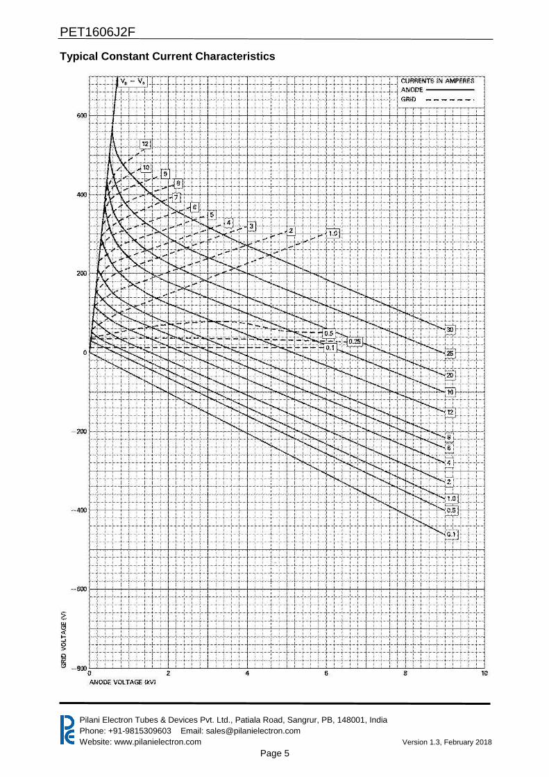
Typical Constant Current Characteristics
PET1606J2F
Pilani Electron Tubes & Devices Pvt. Ltd., Patiala Road, Sangrur, PB, 148001, India
Phone: +91-9815309603 Email: [email protected]
Website: www.pilanielectron.com Version 1.3, February 2018
Page 6
Minimum Water Cooling Requirements (Higher rates of flow should be used where possible)
Typical Water Flow Characteristic
PET1606J2F
Pilani Electron Tubes & Devices Pvt. Ltd., Patiala Road, Sangrur, PB, 148001, India
Phone: +91-9815309603 Email: [email protected]
Website: www.pilanielectron.com Version 1.3, February 2018
Page 7
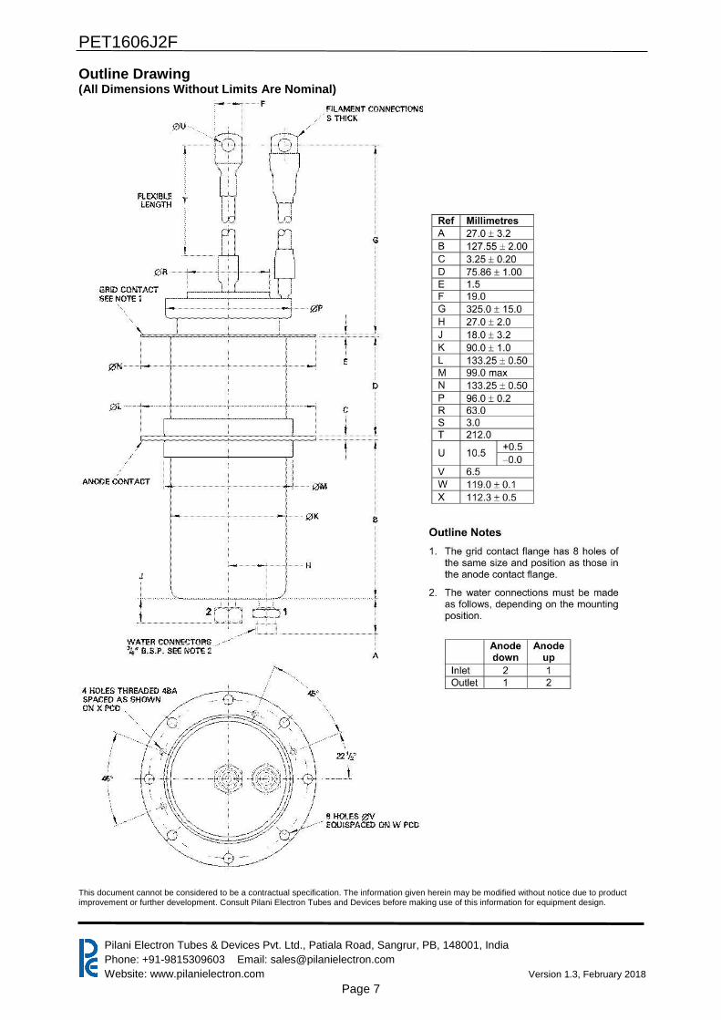
Outline Drawing (All Dimensions Without Limits Are Nominal)
This document cannot be considered to be a contractual specification. The information given herein may be modified without notice due to product improvement or further development. Consult Pilani Electron Tubes and Devices before making use of this information for equipment design.