
Piiion Pine Power Project - National Energy Technology ... Library/Research/Coal/major... · Piiion...
63
DOE/MU29309 ._ 4063 (DE95.009709) Piiion Pine Power Project Annual Report August 1992 - December 1993 November 1994 Work Performed Under Contract No.: DE-FC2 I -92MC29309 For U.S. Department of Energy Office of Fossil Energy Morgantown Energy Technology Center Morgantown, west Virginia BY Sierra Pacitlc Power Company Reno, Nevada
Transcript of Piiion Pine Power Project - National Energy Technology ... Library/Research/Coal/major... · Piiion...
DOE/MU29309 ._ 4063 (DE95.009709)
Piiion Pine Power Project
Annual Report August 1992 - December 1993
November 1994
Work Performed Under Contract No.: DE-FC2 I -92MC29309
For U.S. Department of Energy Office of Fossil Energy Morgantown Energy Technology Center Morgantown, west Virginia
BY Sierra Pacitlc Power Company Reno, Nevada

DISCLAIMER
This report was prepared as an account of work sponsored by an agency of the United States Government. Neither the United States Government nor any agency thereof, nor any of their employees, makes any warranty, express or implied, or assumes any legal liability or responsibility for the accuracy, completeness, or usefulness of any information, apparatus, product, or process disclosed, or represents that its use would not infringe privately owned rights. Reference herein to any specific commercial product, process, or service by trade name, trademark, manufacturer, or otherwise does not necessarily constitute or imply its endorsement, recommendation, or favoring by the United States Government or any agency thereof. The views and opinions of authors expressed herein do not necessarily state or reflect those of the United States Government or any agency thereof.
This report has been reproduced directly from the best available copy.
Available to DOE and DOE contractors from the Office of Scientific and Technical Information, 175 Oak Ridge Turnpike, Oak Ridge, TN 37831; prices available at (615) 576-8401.
Available to the public from the National Technical Information Service, U.S. Department of Commerce, 5285 Port Royal Road, Springfield, VA 22161; phone orders accepted at (703) 487-4650.
DOE/MU29309 -- 4063 (DE95009709)
Dlstribudon Category UC-109
Piiion Pine Power Project
Annual Report August 1992 - December 1993
Work Performed Under Contract No.: DE-FC2 l -92MC29309
For U.S. Department of Energy
Office of Fossil Energy Morgantown Energy Technology Center
P.O. Box 880 Morgantown, West Virginia 26507-0880
BY Sierra Pacific Pbwer Company
P.O. Box 10100 6 100 Neil Road
Reno, Nevada 89520-0400
November 1994
ABBREVIATIONS AND ACRONYMS
CCT CRADA DOE EIS EMP FW USA HRSG IGCC KRW LASH MWK NEPA NFPA PDU PMP PON PSCN PSD SPPCO SUFCO’ UEPA UPS
Clean Coal Technology Program Cooperative Research and Development Agreement U. S. Department of Energy Environmental Impact Statement Environmental Monitoring Plan Foster Wheeler USA Corporation Heat Recovery Steam Generator Integrated Gasification Combined-Cycle Kellogg-Rust-Westinghouse Coal Ash with Spent Limestone The M. W. Kellogg Company National Environmental Policy Act National Fire Protection Association Process Development Unit Project Management Plan Program Opportunity Notice Public Service Commission of Nevada Prevention of Significant Deterioration Sierra Pacific Power Company Southern Utah Fuel Company Utility Environmental Protection Act Uninterruptible Power Supply
. . . 111

TABLE OF CONTENTS
1.0
2.0
3.0 PROJECT OBJECTIVES
4.0 PLANT DESCRIPTION
5.0 SCOPE OF WORK
6.0
7.0
8.0
EXECUTIVE SUMMARY
INTRODUCTION AND BACKGROUND
2.1 IGCC TECHNOLOGY OVERVIEW 2.2 IGCC DEVELOPMENT HISTORY 2.3 PROJECT SELECTION AND COOPERATIVE AGREEMENT 2.4 DESCRIPTION OF EXISTING TRACY STATION
3.1 OVERVIEW OF OBJECTIVES 3.2 DESCRIPTION OF PROJECT PHASES 3.3 ACCOMPLISHMENTS
4.1 PINON PINE POWER PROJECT 4.2 GASIFIER ISLAND 4.3 COMBINED-CYCLE 4.4 OFFSITES
5.1 GENERAL PROJECT REQUIREMENTS 5.2 PROJECT MANAGEMENT 5.3 ENGINEERING AND DESIGN 5.4 PROCUREMENT 5.5 CONSTRUCTION 5.6 ENVIRONMENTAL PERMITTING AND LICENSING 5.7 OPERATION
TECHNICAL IMPACTS ON SCHEDULE
CONCLUSIONS AND LOOK AHEAD
APPENDICES
iv
LIST OF FIGURES
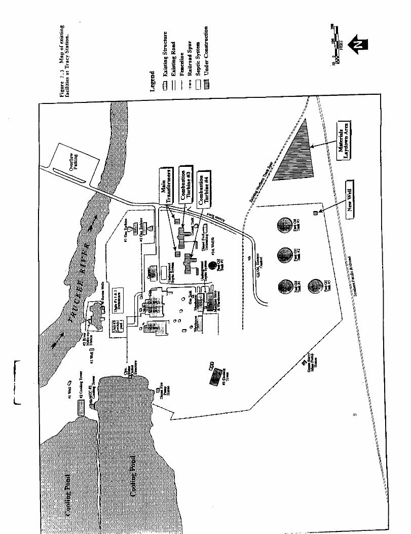
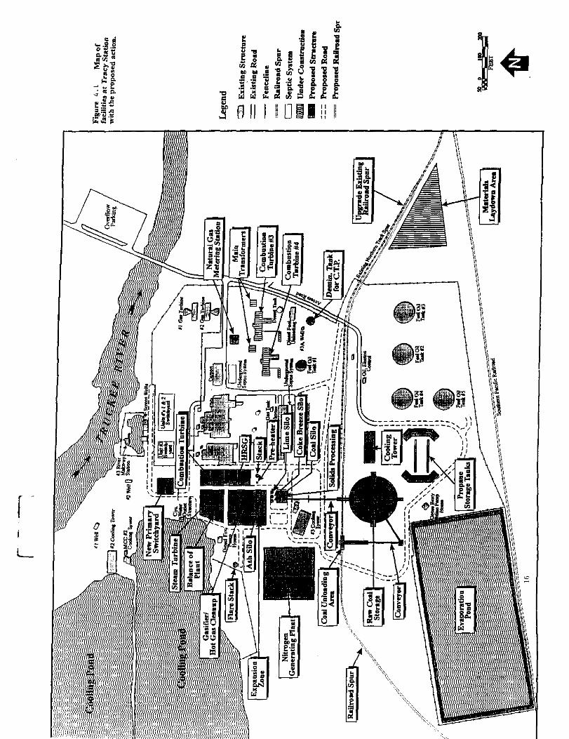
FIGURE 2.1 TRACY STATION LOCATION FIGURE 2.2 TRACY STATION TOPOGRAPHY FIGURE 2.3 MAP OF EXISTING FACILITIES AT TRACY STATION FIGURE 4.1 h4AP OF FACILITIES AT TRACY STATION WITH THE PROPOSED
ACTION
V
1.0 EXECUTIVE SUMMARY
This annual report has been prepared to present the status of the Pifton Pine Power Project, a nominal 104 MWe (gross) integrated gasification combined-cycle (IGCC) power plant addition to Sierra Pacific Power Company’s (SPPCo) system. This project will also serve as a demonstration project cost-shared by the U.S. Department of Energy (DOE) and SPPCo under DOE’s Clean Coal Technology (CCT) Program. The goal of the CCT Program is to demonstrate advanced coal utilization technologies that are energy efficient and reliable and that are able to achieve substantial reductions in emissions as compared with existing coal technologies.
The Pinon Pine Power Project will demonstrate an IGCC system utilizing the Kellogg-Rust-Westinghouse (KRW) fluidized-bed gasification process operating in an air-blown mode with in-bed desulfurization and hot gas clean-up with a western bituminous coal. The Pifton Pine Power Project will be constructed and operated at SPPCo’s Tracy Power Station, an existing power generation facility located on a rural 724-acre plot approximately 17 miles east of Reno, NV (Appendix 1).
SPPCo., the project participant, has contracted with the Foster Wheeler USA Corporation (FW USA) for the overall project management, engineering, procurement and construction of the project. FW USA in turn has subcontracted with The M. W. Kellogg Company (MWK) for the engineering and procurement of key components for the Gasifler Island.
Key accomplishments have been the following:
Performed testing of zinc based sorbent for desulfurization of the fuel gas. Ash melting point test, coal reactivity tests with the design coal, and fluidization test with coal char were also conducted.
Completed mapping studies with design coal to develop an operating envelope for the KRW gasifier.
Executed purchase of GE Frame 6Fa gas turbine generator (GE was only released for engineering).
Issued heat and material balances and process flow diagrams.

Completed technical reports for preparation of the Environmental Impact Statement (EIS)
Completed technical definition for the Class III Estimate.
As a result of the delay in the selection of the combustion turbine as well as the extended environmental activities, progress has been slower than originally planned, with expenditures also limited over the period. Nevertheless, despite the deIays encountered, the start of the Demonstration Period (Phase III) is not currently projected to be affected. However, the initial plan to implement a phased construction approach, with installation and operation of the combustion turbine as a peaking unit, will not be implemented because of the installation of approximately 160 MWe of peaking capacity to be operational in mid 1994.
2.0 INTRODUCTION AND BACKGROUND
2.1 IGCC Technolozv Overview
Coal-fired power plants are still the mainstay of power generation world-wide. The emissions produced by coal combustion have led to an environmental burden to the point where the use of coal as fuel for electricity generation may be threatened. Parallel to the installation of flue gas scrubbers in conventional coal- fired power plants, research is proceeding on innovative power plant concepts which are not only more acceptable from an environmental standpoint but also feature higher efficiency. Technology of this kind is already available for oil and gas fuels in the form of combined cycle gas and steam turbine power plants. To apply combined cycle technology to power production from coal, conversion of coal to a gaseous fuel is required by a coal gasification process. The most common coal gasification process essentially involves partial combustion of coal. This partial combustion provides the energy for further conversion of coal primarily into carbon monoxide and hydrogen.
In many regions in the United States, the effective electric reserves have declined to low levels and it is predicted that there will be a surge in new power plant orders. The criteria used for selecting a power plant technology will have to take into consideration cost competitiveness, environmental superiority, module size, fuel flexibility, reliability and availability, and construction lead time. Based on these criteria, IGCC technology is a leading candidate for new capacity addition. Demonstration of this technology should provide a coal-based option with cost of electricity that is competitive with more conventional technologies.

The Pifion Pine Power Project to be located at SPPCo Tracy Station will incorporate the KRW gasification technology which produces a clean low-Btu gas for use as fuel in a combined cycle power plant for production of low cost electricity in an environmentally sound manner.
The KRW process improves upon first generation IGCC technology in several aspects. Its pressurized, air-blown fluidized bed gasification technology will provide a higher thermal efficiency than a similar oxygen-blown system because it consumes less auxiliary power. A portion of the sulfur pollutants are captured within the fluidized bed before they can exit the gasifier. Additional impurities are removed through an advanced hot gas cleanup system which operates with a regenerative sulfur sorbent to remove sulfur compounds and barrier filters to remove particulates. In addition, the inherent modular design of the system and simple process configuration are expected to yield significantly lower engineering and construction costs.
The Piiion Pine Power Project integrates a number of technologies fostered by DOE. Among these are the KRW Energy Systems fluidized-bed gasifier, in-bed desulfurization using limestone sorbent, and zinc based sorbent sulfur removal from a hot gas stream. DOE and its predecessor agencies have supported development of this fluidized-bed gasification technology since 1972 when the design of a process development unit (PDU) was first initiated under contract with Westinghouse Electric Corporation. Construction of the PDU was completed in 1975 at Westinghouse’s Waltz Mill Facility near Madison, Pennsylvania. From 1984 to 1988 the addition of dolomite and limestone to the gasifier bed for in-bed sulfur removal was successfully demonstrated at the PDU. These tests indicated that 85 to 90 percent sulfur removal efficiencies could be routinely achieved while using coal feedstocks containing 2 to 4.5 percent sulfur. In addition, the use of these sorbents in the gasifier was found to increase the product gas heating value while decreasing the production of ammonia, a major contributor to NO, emissions.
It is important that a demonstration of the advanced IGCC technology include actual integration of the gasifier with a combined-cycle power plant. This step is necessary in order to evaluate the adequacy of integrated control concepts and to measure actual performance of a complete power generation system on a utility grid. The modular concept of the proposed technology will provide information that is directly applicable to other commercial plants since such plants will essentially incorporate one or more replicates of the demonstration project plant configuration.
3

2.2 IGCC Development History
Almost all of the IGCC demonstration plants were designed around a more conventional approach, i.e., gas produced in the gasifier was either quenched or cooled and scrubbed for low temperature removal of sulfur compounds. These plants also removed ash/slag in a wet state. In order to limit the size of cool down trains and desulfurizer systems, gasifiers for these early plants were oxygen blown, thereby adding to capital cost and parasitic power consumption. Cooling of gas for sulfur removal not only lowered the cycle efficiency, but also required extensive equipment and handling of process water. These plants offered the advantage of reduced number of gasification trains and offered flexibility to adapt them to chemical production.
In order to meet challenges of the market place and environment, a simplified IGCC system incorporating air-blown gasification with hot gas cleanup has been developed. By eliminating the oxygen plant and minimizing the need for gas cooling and wastewater processing equipment, the capital cost is reduced and plant efficiency is improved. Key features of the simplified IGCC system are shown in Appendix 2 and described below:
. Air-Blown Gasification
In the simplified IGCC system, about 15 to 20 percent of the gas turbine compressor discharge air is extracted for use as oxidant in the gasifier. A booster air compressor increases the pressure of this extracted air to compensate for pressure losses through the gasifier and downstream hot gas cleanup system and fuel control valve.
. Hot Gas Cleanup
To date, most major gasification plants have utilized cold (wet) cleanup processes. The alternate approach of filtering the gas at high temperature enables the gas to maintain most of the sensible heat resulting in a higher plant efficiency. Equipment is minimized and there is no waste water production. Several types of filtering devices have been tested in pilot facilities and are available from several suppliers.
4

3.0 PROJECT OBJECTIVES
3.1 Overview of Obiectives
The objectives of the Pirion Pine Power Project are to meet the power needs of the SPPCo customers and to demonstrate the technical, economic and environmental viability of a commercial scale IGCC power plant. This plant is to be based on an air blown, fluidized-bed gasifier incorporating hot gas clean up and a combustion gas turbine capable of utilizing low Btu gas. The project will demonstrate that power plants based on this technology can be built at capital costs and with thermal efficiencies which significantly reduce electric power costs over more conventional technologies. The project will also demonstrate the effectiveness of hot gas clean-up in achieving a negligible environmental impact (reduced SO, and NO, emissions) and the operation of a low-Btu fuel gas combustion turbine. The performance to be demonstrated will include all major sub-systems of the IGCC system including coal and limestone feed systems, pressurized air-blown fluidized bed gasifier, hot product gas filtering and desulfurization with a regenerative sulfur sorbent, sulfator system, combustion turbine and steam cycle, and integrated control systems. Another objective is to assess the long term reliability, maintainability, and environmental performance of the IGCC technology in a utility setting at a commercial module size.
3.2 Proiect Phases
The Pirion Pine Power Project will be divided into the following three distinct phases of activity as shown in the Summary Bar Chart Project Schedule included in Appendix 4:
3.2.1 Phase I - Desien
The objective of activities during this phase is to provide the technical definition and definitive cost of the Piiion Pine Power Project. This effort provides process design, equipment identification and selection, integration of the gasifier system with the power plant, and system test planning as required to make certain that adequate design features exist to assure performance and operational success. Also, all required engineering information and support for all licensing, permitting and reliability activities will be prepared during this phase.
10

3.2.2 Phase II - Construction
This phase includes all activities required to construct the plant in concert with the overall project plan. This will ensure that the facility is procured and constructed to specification, on schedule, and within budget. Procurement activities during this task include purchasing, inspections, expediting, traffic and commercial aspects of in-place subcontracting. Included in this effort are home office construction activities such as safety, quality assurance, labor relations, budgeting and scheduling, and field construction management activities including functions such as supervision of equipment installation, erection of materials, field engineering, field accounting, cost, schedule and material control, and subcontract administration.
3.2.3 Phase III - Oueration
This phase covers all the labor, materials and services needed for plant operation for a 42-month period. The objective is to provide all the operational and management direction that will be necessary to provide the private sector with technical, economic and environmental evaluations on the advanced coal gasification combined-cycle power plants.
3.3 Accomplishments
This section of the report provides a summary of major activities and accomplishments through December 1993.
3.3.1 Laboratorv Testing
Coal reactivity tests were performed using the thermogravimetric analyzer using char prepared from SUFCO coal and char prepared in presence of limestone. Four tests were done on each of the two samples.
Ash melting points were determined using the hot-stage microscope. Ash samples were prepared with SUFCO coal and SUFCO coal with limestone. Four sets of initial sintering, initial melting and final melting temperatures for the two types of ash were determined.
11

Fluidization tests were conducted in a 1.375” I.D. cold flow model unit using 22 wt% coal char without limestone and coal char containing 20 wt% calcium oxide at three superficial velocity vs. complete fluidization velocity ratios to establish the magnitude of reduction in fines elutriation due to addition of limestone to the gasifier.
Testing of zinc ferrite and zinc titanate as candidates for the sulfur sorbent in the hot gas clean-up system were conducted under a Cooperative Research and Development Agreement (CRADA) between DOE-METC and MWK. Zinc ferrite displayed a tendency to break up after repeated regenerations. Zinc titanate demonstrated initial encouraging results. However, it also began to display a tendency to decrepitate.
The SPPC/MWK/METC CRADA testing to evaluate the use of Z-SORB III sorbent in desulfurization of the fuel gas from the gasifier was completed. The testing indicated that this sorbent has better mechanical durability than zinc ferrite and zinc titanate sorbents. Although the absorption capacity was observed to decline as the test runs proceeded, the reduction in capacity tended toward stabilizing within acceptable limits when the testing ended. The process design work is proceeding based on utilizing a zinc based sorbent such as Z-SORB III sorbent for fuel gas desulfurization with dry regeneration.
3.3.2 Process
Gasifier mapping work was started to develop an operating envelop for the KRW gasifier with SUFCO coal feed and local limestone.
Several computer runs were made with in-house gasifier design programs using the gasifier operating temperature, carbon conversion, fuel gas lower heating value and the gasifier volume as the key variable. All results were plotted and included in the report.
While the mapping work was in progress the laboratory coal reactivity tests confirmed that SUFCO coal relative reactivity was actually slightly better than the proposal value which validated the proposal design.
The initial issue of the process flow diagrams and equipment list were completed and reviewed by the project team. The latest revision of these documents provided the basis for the Class III Cost Estimate.
12

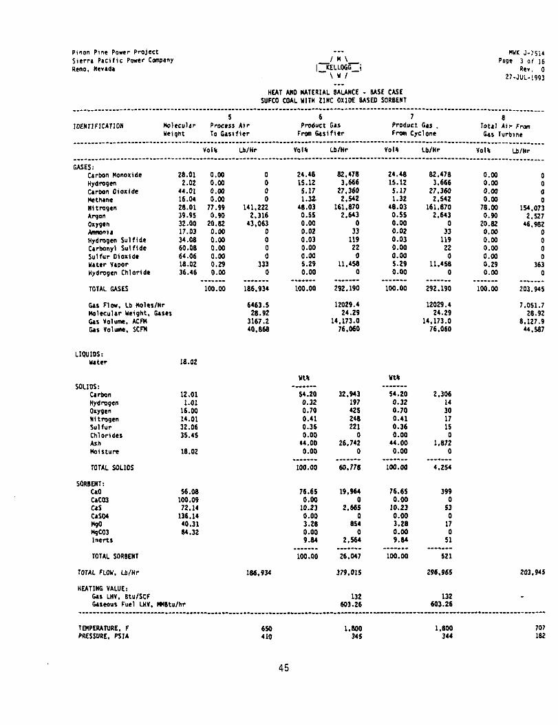
The Gasifier Island heat and material balances for the Base Operating Case, Maximum Coal Throughput Case and the 60% Turndown Case were completed along with the utility consumption (steam, water, and power) for all three process cases. Heat and material balances for the Base Operating Case are included in Appendix 3.
The plant thermodynamic model was completed based on the Gasifier Island heat and material balances and the gas turbine generator performance data furnished by GE. The steam turbine generator throttle steam pressure and temperature were evaluated. Seven pressure/temperature conditions were studied ranging from 900 psia/900”F to 1500 psig/lOOO°F. Based on these evaluations, which included estimated equipment costs and turbine generator output, 950 psia/950”F was selected as the throttle pressure/temperature.
An economic analysis of potential cooling methods for the plant was completed. These studies covered systems ranging from the use of cooling pond, cooling pond with supplemental cooling tower, stand-alone cooling tower, spray pond, wet-dry cooling tower and air cooled condenser with auxiliary cooling tower. Based upon these studies, including the preparation of order of magnitude estimates, the selection of a conventional cooling tower utilizing a closed loop cooling water system and surface condenser was recommended.
3.3.3 Eneineering
The technical definition for the Class III Estimate was developed including alternative arrangements for cost reduction options. This estimate will update the project costs to reflect the gas turbine generator selected for the project along with size changes of associated plant facilities.
The purchase contract for the GE Frame 6Fa gas turbine generator was executed. However, GE was released to proceed with engineering only. GE drawings transmittals are underway commencing with performance runs to define the gas turbine operating envelope (i.e., determining the effects of variations in ambient air temperature, load, fuel composition, fuel temperature, air extraction rate and other factors).
13
Preparation of the project job specifications is underway. These specifications are being prepared by FW USA and reviewed by MWK and SPPCo to maximize consistency in plant design and construction.
The requisition and specifications for the site survey and geotechnical investigation subcontract were completed and issued for inquiry.
3.3.4 Environmental/Permittine Activities
SPPCo and its contractors, Ebasco and ENSR, have provided DOE technical reports in support of DOE’s preparation of the EIS. These reports covered the following subjects:
- Air Quality - Water Resources - Solid & Hazardous Wastes - Cultural Resources - Socioeconomics - Biological Resources - Health, Safety and Noise - Geology, Soils and Seismicity - Visual Resources
Also prepared in this effort was a technical description of the plant prepared by FW USA and MWK. These technical reports were provided in sufficient detail to enable the DOE and its contractors to prepare the EIS.
SPPCo also completed its Prevention of Significant Deterioration (PSD) permit application and filed it with the State of Nevada. It is complete with the exception of the incorporation of additional meteorological data currently being gathered at the Tracy Plant site.
SPPCo has completed the presentation of its 1993 Electric Resource Plan to the Public Service Commission of Nevada (PSCN). The PSCN issued an Interim Opinion and Order giving SPPCo approval to proceed with the Piiion Pine Project.
14
4.0 PLANT DESCRIPTION
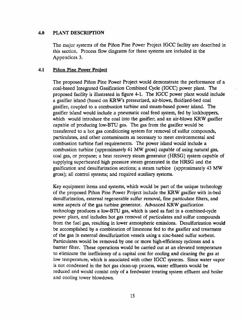
The major systems of the Pifion Pine Power Project IGCC facility are described in this section. Process flow diagrams for these systems are included in the Appendices 3.
4.1 Pition Pine Power Proiect
The proposed Piiion Pine Power Project would demonstrate the performance of a coal-based Integrated Gasification Combined Cycle (IGCC) power plant. The proposed facility is illustrated in figure 4-1. The IGCC power plant would include a gasifier island (based on KRW’s pressurized, air-blown, fluidized-bed coal gasifier, coupled to a combustion turbine and steam-based power island. The gasifier island would include a pneumatic coal feed system, fed by lockhoppers, which would introduce the coal into the gasifier; and an air-blown KRW gasifier capable of producing low-BTU gas. The gas from the gasifier would be transferred to a hot gas conditioning system for removal of sulfur compounds, particulates, and other contaminants as necessary to meet environmental and combustion turbine fuel requirements. The power island would include a combustion turbine (approximately 61 MW gross) capable of using natural gas, coal gas, or propane; a heat recovery steam generator (HRSG) system capable of supplying superheated high pressure steam generated in the HRSG and the gasification and desulfurization sections; a steam turbine (approximately 43 MW gross); all control systems; and required auxiliary systems.
Key equipment items and systems, which would be part of the unique technology of the proposed Pirion Pine Power Project include the KRW gasifier with in-bed desulfurization, external regenerable sulfur removal, fine particulate filters, and some aspects of the gas turbine generator. Advanced KRW gasification technology produces a low-BTU gas, which is used as fuel in a combined-cycle power plant, and includes hot gas removal of particulates and sulfur compounds from the fuel gas, resulting in lower atmospheric emissions. Desulfurization would be accomplished by a combination of limestone fed to the gasifier and treatment of the gas in external desulfurization vessels using a zinc-based sulfur sorbent. Particulates would be removed by one or more high-efficiency cyclones and a barrier filter. These operations would be carried out at an elevated temperature to eliminate the inefficiency of a capital cost for cooling and cleaning the gas at low temperature, which is associated with other IGCC systems. Since water vapor is not condensed in the hot gas clean-up process, water effluents would be reduced and would consist only of a feedwater treating system effluent and boiler and cooling tower blowdown.
15
,,:..
4.2
Raw coal, from western States, would be received at the plant from a unit train consisting of approximately 84 railcars of between lOO- and llO-ton capacity, arriving approximately once a week. Currently, Southern Pacific Railroad facilities are on site; the railroad line is a main east-west supply route. Upgrading and extending the spur on SPPCo. land would be required for the proposed project.
Coal would be received at an enclosed unloading station and transferred to a coal storage dome. The unloading station would consist of two receiving hoppers, each equipped with a vibrating-type unloading feeder that would feed the raw coal conveyor systems. All material handling systems would be enclosed and supplied with dust collection systems for environmental control. Dust control equipment would be permitted as required by State and Federal regulations.
Gasifier
Coal and limestone (as well as coke breeze during start-up) are fed from a single conveyor to the atmospheric feed surge bin. This bin periodically discharges solids into feed pressurization lockhoppers from where coal and limestone are fed to the gasifier on a continuous basis by a rotary coal feeder.
Solids from the feeder are picked up by transport air and fed directly to the gasifier central feed tube. Additional heated air from the recuperator is also fed through the same feed tube and the streams merge to form a central jet where the coal is quickly devolatilized, with the remaining char and limestone entering the bed. Extraction steam from the steam turbine and recycle gas are also fed to the gasifier bed to serve as reactant and bed fluidization media. Carbon monoxide and hydrogen form the major combustible constituents of the product gas.
Air for the gasifier island is extracted from the gas turbine air compressor. A portion of this air is diverted for use in start-up or to furnish the air required for regeneration of the zinc based desulfurization sorbent. The major portion of the air is cooled and compressed to above gasifier operating pressure. The air exiting the boost air compressor is reheated in the air recuperator and fed to the gasifier. A portion of this compressed air is cooled for use as coal transport air to feed solids into the gasifier and another stream is further compressed to serve as pressurization gas for the feed lo&hopper system.
Gasification also results in the release of sulfur from the coal, primarily in the form of hydrogen sulfide some of which is absorbed by calcined limestone in the gasifier bed to form calcium sulfide. This calcium sulfide is withdrawn with coal
17
ash and unconverted char via the gasifier annulus which is fluidized and cooled by a stream of recycle gas. The spent solids leaving the gasifier are transferred via the ash feeder to the ash lo&hopper system for collection and delivery to the sulfator.
The product gas exiting the top of the gasifier contains a significant quantity of entrained solids. The product gas passes through the gasifier cyclone which removes most of the solids and returns these to the gasifier bed. Gas from the cyclone is directed to the product gas coolers for heat recovery and steam generation.
Product gas from the gas coolers is sent to the hot gas filter which removes essentially all of the remaining particulates. The particulate free gas from the hot gas filter is sent to the desulfurization system for removal of sulfur compounds. Sulfur compounds are reduced in the gas by a zinc based sorbent. The desulfmization system consists of two vessels each having a packed bed of the sorbent. One bed operates in a sulfidation mode while the second bed is either being regenerated or is on standby. A hot diluted air stream is utilized for sorbent regeneration. The sulfur dioxide rich gas from regeneration is sent to the sulfator for sulfur dioxide capture.
A stream of gas exiting the desulfurizer system is cooled for use as recycle gas. A portion of the cooled recycle gas is used for solids transport in the sulfator system. The major quantity of recycle gas is compressed for use as gasifier fluidization gas, filter blowback gas, and ash and filter lockhopper system pressurization gas.
The clean fuel gas exiting the desulfurization system is passed through the guard cyclone to capture any solids in the gas stream and collects them in the solids drum. Normally, it is expected that gas will be free of solids, however, the guard drum is added as a protective device for the gas turbine.
Fines removed by the filter elements are collected in the bottom of the filter vessel, cooled and discharged through the filter fines lockhopper system.
Vent gas from the ash and the filter fines lo&hopper is routed to the sulfator.
With the exception of a small quantity of sulfur in the fuel gas to the gas turbine, all of the sulfur in coal is ultimately disposed of in the sulfator system. In addition to oxidation of calcium sulfide produced in the gasifier to calcium suIfate, the sulfator system also combusts residual char in the ash and fines collected from
18

gasification and captures sulfur dioxide from both the residual char combustion and the desulfurizer regeneration effluent gas. Also, a small recycle gas stream (transport and pressurization gas) is combusted in the sulfator. All of these reactions are highly exothermic.
The sulfator is a bubbling bed reactor which is fluidized by air supplied by the sulfator air compressor. Solids exiting the gasifier bottom are conveyed from the ash lo&hopper system to the sulfator with cooled recycle gas. Fresh limestone, from the limestone feed hopper is fed by using instrument air to pressurize it into the sulfator during normal operation. The sulfator bed temperature is controlled by generating saturated steam in the primary solids cooler.
Filter fines from the lockhopper system are conveyed by a stream of recycle gas to the fines combustor to bum off carbon for additional heat recovery.
Flue gas leaving the sulfator passes through the sulfator cyclone and is then mixed with flue gas from the fines combustors prior to cooling in the heat recovery steam generator. Gas cooling is accomplished by generation of high pressure steam and preheating of boiler feedwater. All of the steam generated in the gasifier island is slightly superheated prior to export to the power island. The flue gas then passes through the sulfator flue gas bag house filter and is sent to the stack.
Solids leaving the bottom of the sulfator are cooled in the sulfator solids screw cooler, withdrawn through a lockhopper system and are discharged on to a conveyor for storage and disposal by truck.
4.3 Combined-Cwle
A General Electric Model MS6OOlFA Gas Turbine Engine (70.1 MW IS0 rating) has been selected as the prime mover for the Pirion Pine Power Plant. It is an industrial frame-type gas turbine, scaled-down from GE’s MS7001FA (150 MW) model. The technologically advanced firing temperature and cooling system of F- class gas turbines provide such units operating in combined cycle power plants with the highest total-cycle efficiency of any proven type of fossil-fueled electric power generation system. The engine’s output shaft power will be reduced in rotative speed in a gearbox, from the optimum-efficiency value for a gas turbine of this size. Mechanical power will then be converted to electrical power in a once- through air-cooled synchronous generator.
19
Available thermal power in the exhaust gases will be captured in a heat recovery steam generator (HRSG) to drive a condensing steam turbine generator.
The HRSG generates steam at three pressure levels. Steam generated in the HRSG and high pressure steam generated in the Gasifier Island, are combined, superheated in the HRSG and sent to the steam turbine generator. Low pressure steam generated is sent to the steam turbine generator and provides pegging steam for the deaerator heater.
The steam turbine generator is a condensing type. Extractions provide steam, after letdown and desuperheating, to the gasifier. Throttle steam letdown is used if and when low throttle steam rates cause the extraction pressure to fall unacceptably low. Additionally, this extraction will provide steam for injection at the gas turbine generator for NO, control when operating on natural gas or propane fuel.
The steam turbine has an additional extraction providing steam to the boiler feedwater preheater.
The steam turbine exhausts into a surface condenser. Cooling water is used to condense the exhaust steam. Condensate is pumped from the condenser by the hotwell condensate pumps through the boiler feed water preheater for the recovery of low level heat and thence to the deaerator. Venting of the condenser is accomplished by a vacuum pump system.
High pressure boiler feed water is pumped from the deaerator to the evaporator and Gasifier Island by the high pressure boiler feedwater pumps. High pressure boiler feedwater to the high pressure evaporator is preheated in an economizer section of the HRSG. Deaerated low pressure boiler feed water is pumped to the low pressure evaporators by the low pressure boiler feed water pumps. Boiler feedwater is preheated in an economizer section of the HRSG.
4.4 Offsites
Raw coal, size 2” x 0, is received at the plant from a unit train consisting of up to eighty-four 100 ton railcars approximately every seven days. The coal is received at the enclosed unloading station and transferred to the coal storage dome. The unloading station will be enclosed and provided with a dust collection system to avoid uncontrolled coal dust emissions. The unloading station consists of two receiving hoppers, each equipped with belt type unloading feeder which feed the
20
raw coal conveyor system. The conveyor system consists of the raw coal transfer conveyor and raw coal elevating conveyor. All material handling systems will be supplied with dust collection systems for environmental control, with special attention being paid to dust generating areas such as transfer points. Coal is weighed in transit by the raw coal receiving scale located on the raw coal transfer conveyor. An automatic sampling system is located at the discharge of the raw coal transfer conveyor which collects a representative sample to determine the quality of coal received. The raw coal unloading and conveyor system is sized to handle an 84 railcar train unloading operation in a four-hour period.
The coal is stored in a large field erected storage dome which will be sized to store over 16,000 tons of coal, or approximately twenty day’s requirement. No exposed storage of coal, such as a coal pile, is planned, thus all coal storage will be within the dome.
Coal in the storage dome is reclaimed by the automated coal pile reclaimer or discharged by emergency pile dischargers and vibratory feeders onto the raw coal collecting conveyor. This conveyor transfers the coal to the crushing station for crushing and screening.
In coal crushing and screening, the raw coal passes through a magnetic separator and is fed to the hammer mill to reduce the material size from 2’ x 0” to W x 0”. The vibrating screen with %” square holes under the crusher will control the product top size. Oversize material will return to the mill for further reduction through the bucket elevator. The product-size material is conveyed away by a high angle conveyor and deposited in the coal silo. The coal silo is sized for 24- hour feed to the gasifier.
Two parallel systems of gasifier feed conveying equipment are provided from the coal silo to the gasifier area. Each line of the conveying system consists of a weigh belt feeder, a gathering conveyor and an elevating conveyor. One system will be operating continuously while the other will be a standby spare. Each conveying line can be utiliied to handle coal, limestone and coke. As with the raw coal handling system, care will be taken to control any dust emission sources by means of dust collection system.
Dried coke breeze, W’ x 0, is received in the plant via trucks with pneumatic trailers for initial plant start-up and for each subsequent gasifier start-up. The sized coke is conveyed pneumatically to an 800 ton capacity coke storage silo using the truck-trailer pneumatic blower. Exhaust air from the filling operation
21
will be vented through a dust control filter system. The material from the coke silo is conveyed to the gasifier utilizing one of the coal conveyor systems. The coke silo will be equipped with a weigh feeder to feed the said coal conveyor system.
Sized limestone is received in the plant via trucks with pneumatic trailers on a daily basis. The sized limestone is conveyed pneumatically to a 300 ton (5-day) capacity limestone storage silo using the truck trailer pneumatic blower. Exhaust air from this filling operation will also be vented through a dust control filter system. The material from the limestone silo is then fed at a controlled rate by a weigh feeder and blended with the coal on the same conveying line feeding the gasifier. Provisions are also included to transport limestone to the sulfator limestone feed hopper by pneumatic conveying. The material is discharged from the limestone silo and fed to the pneumatic conveying line by rotary airlock feeder. Two redundant systems are provided with one operating and the other as standby spare.
Dust collection systems will be provided in the plant for proper environmental control. Fabric filter collectors will be used to control fugitive dust emissions from the transport and transfer of coal, coke and limestone.
Wastewater from the demineralization package and cooling tower blowdown will be discharged to the wastewater collection system. The wastewater system will discharge to a wastewater sump. The wastewater sump pumps will pump this effluent to the evaporation pond.
The pond will be double lined and the system will be designed to meet the requirements of the Nevada Division of Environmental Protection. The pond surface area (approx. 10 acres) is minimized by the use of floating water spray units. These are located across the pond surface, each equipped with its own electric drive system. Water is pumped up through each unit and sprayed across the pond surface improving the evaporation rate. The wastewater is not anticipated to result in any adverse effect on wildlife such as migrating water fowl. Monofilament line with 25’ spacing has been used by SPPCo to successfully discourage migrating water fowl from landing in several of SPPCo’s facilities and is unobtrusive to the human observer.
22

Cooled solid waste (LASH) consisting of ash, fines and sulfated limestone from the sulfation unit is conveyed continuously to the solid waste storage silo using a belt conveyor system. The air displaced from the silo and the conveyor is vented through the bin filter.
The LASH in the silo is loaded-out onto trucks during the day shift operation, 5 days per week. The silo is equipped with a bin discharger, discharge valve and a telescopic loading chute with a bag filter and fan to minimize dusting during the truck loading operation. The LASH is then hauled to the final disposal point. A local landfill has expressed interest in using the material as a cover, and other usages are being investigated.
The solid waste silo is sized for three days of storage (400 tons) to handle the solid waste production over the weekend without the need of the truck load-out operation.
The raw water system provides water to the demineralization package which in turn provides boiler feedwater makeup to the deaerator. Additionally the raw water system provides water for the plant utility water system for miscellaneous users such as service wash stations. Well water is the source of water for the plant raw water system. Well water is pumped to the existing Unit 3 raw water tank and then pumped by the raw water pumps to the plant raw water system.
River water provides makeup water for the cooling tower. Raw water is pumped from the existing river water intake to the cooling tower basin by the river water pumps.
Water for safety showers and eyewashes will be provided by the existing plant system. Drinking water is provided as a brought-in bottled source.
Fire protection water will be provided by the existing plant system to the fire protection water loop. The source of fire protection water is the existing cooling pond. Three fire protection water pumps are presently installed together with a jockey pump.
Makeup boiler feedwater is demineralized by a package consisting of cation, degasification, anion and mixed bed units. Also included are the storage and feeding of regenerating caustic and sulfuric acid, and appropriate local controls, including neutralization controls. Spare acid and caustic pumps and the neutralization air mixing system are also included.
23

Regeneration waste is stored in a neutralization tank, where the waste is mixed and neutralized before it is sent to the dirty water sewer. Acid and caustic pumps are provided for neutralization.
Demineralized water is stored in a storage tank and pumped to the condensate system by the demineralized water pumps.
A chemical injection package consisting of facilities to feed and control appropriate quantities of oxygen scavengers, scale and corrosion inhibitors, and filming and neutralizing agents to the appropriate locations within the boiler feedwater system is provided.
A conventional induced-draft counter-flow cooling tower will be used for the plant cooling water system. The basin is below grade. Cooling water is circulated by the vertical turbine cooling water pumps.
The cooling tower is designed for the 2%% occurrence condition of a 61°F wet bulb temperature and provides 71 “F cooling water at that condition. ,Blowdown from the system will be sent to the evaporation pond.
Biocide injection is provided by a biocide feeder. Other additives, corrosion inhibitors, pH control biocides, and scale/deposit inhibitors, are injected into the cooling water by the water treatment injection system.
A conventional plant and instrument air compression system is provided. Two air compressors, one operating, one spare, are provided for the system. A single air receiver provides adequate surge capacity. The air is dried to a -4O’F dewpoint using an air drying desiccant system prior to branching off to plant and instrument air headers.
A flare system is provided to incinerate the full product gas flow from the gasifier in the event of a power plant outage, gasifier start-up, or other emergencies. The flare is a vertical free-standing system. Pilots wig be designed to use natural gas or propane.
Propane is planned as a tertiary emergency fuel to the combustion gas turbine. Liquid propane will be delivered by tank truck or tank car and stored in two 100,000 gallon (nominal) storage drums. The drums will be oriented, and earthen berms constructed, to minimize damage in tlie event of tank failure. Storage will be in accordance with the applicable NFPA requirements. When required, liquid
24
propane is drawn off the storage drums and pumped to the vaporizer prior to combustion as fuel in the combustion gas turbine.
Nitrogen is required by the process for regeneration of the sulfur absorbing sorbent, maintaining a constant flow of purge gas through selected equipment and instruments, blow back cleaning of the hot gas filter (when normal process gas is unavailable), pneumatic conveying of coal dust and system purging at shutdown.
The nitrogen package is a cryogenic air separation plant wherein the constituents of air are separated by cryogenic distillation delivering high purity nitrogen in the required quantity. Components of the package include compressors, storage tanks, a liquid nitrogen pump and vaporizers sized to provide for start-up, normal operation and a safe shutdown of the facility.
The existing Tracy sub-station is supplied at 120 KV. Connection to this system will be through tie and service breakers feeding unit transformers connected to the gas and steam turbo-generators. The generators will be rated at 13.8 KV with maximum generator output equal to elevated temperature and/or auxiliary cooling transformer rating as required. The auxiliary power will be fed from each generator transformer servicing large motors 250 hp and over at 4.16 KV and 480 V for general distribution. The 4.16 KV and 480 V will be radial distribution. A second feeder from an existing 4.16KV transformer will permit alternate service in the event of maintenance turnarounds or equipment outages. However, this transformer will not be able to carry the coal gasification process in addition to the generator auxiliaries.
Auxiliary systems within the plant will be provided through UPS or DC Batteries to support personnel safety and critical equipment during shutdowns or power outages where required.
5.0 SCOPE OF WORK
5.1 General Proiect Reauirements
The objective of this project is to demonstrate IGCC at a large scale for use in commercial electric generating plants. The project is to demonstrate equipment and system operability, performance and reliability, as well as process performance in removing sulfur dioxide and minimizing the formation of oxides of nitrogen. The specific goal of the project is to demonstrate that the air-blown IGCC technology is a cost effective, reliable, more efficient and environmentally superior
25

alternative to conventional coal-fired electric power generation with flue gas desulfurization.
The project is aimed at demonstrating IGCC technology in a plant that is to be integrated into the SPPCo system. SPPCo proposes to design, construct and operate a grass-roots, integrated coal gasification combined-cycle facility at its Tracy Station near Reno, Nevada.
In this application of the process, one KRW gasifier, operating in the air blown mode with in-bed desulfurization and hot gas cleanup technology, will convert approximately 800 tons per day of bituminous coal into a low BTU fuel gas for use in a combustion turbine generator. The exhaust gases from the turbine will generate steam in an HRSG to drive a steam turbine generator. The plant will produce a nominal 95 MWe (net) of total electric power.
5.2 ProiectManaeement
The project will be centrally managed by the Project Director of SPPCo. All management, reporting, and project reviews for the project shall be as required by the Cooperative Agreement. The Project Director shall be the official point of contact between SPPCo and DOE for the execution of the Cooperative Agreement. The Project Director shall be responsible for assuring that the project is conducted in accordance with the cost, schedule and technical baseline established in the Project Management Plant (PMP) and subsequent updates.
SPPCo has entered into the management and execution of a contract with FW USA for design and construction of the facility. MWK will be a subcontractor to FW USA for the design of the KRW fluidized bed gasification process.
Implementation details for all tasks shall be provided in a detailed schedule and Work Breakdown Schedule for the overall project presented in the PMP. An outline matrix of planned tests and procedures for the operational phase of the project shall be included to ensure that the basic design and installation philosophy match required operating and testing philosophies. The PMP shall be updated during each budget period of the project to reflect changes to the project baseline.
The Project Team under the direction of the Project Director will be responsible for coordination, monitoring and reporting requirements in accordance with the Cooperative Agreement.
26

5.3 EnzineerinP and Design
This effort provides process design, equipment identification and selection, integration of the gasifier system with the power plant, and system test planning as required to make certain that adequate design features exist to assure performance and operational success. The engineering and design effort is split into three separate tasks:
5.3.1 Gasifier Island
The areas of the plant addressed under this task include:
Area 200 Area 300 Area 400 Area 500 Area 600 Area 900
Oxidant Compression and Supply Coal Gasification Gas Stream Heat Recovery Gas Stream Particulate Removal Desulfurization Recycle Gas Compression
a. Process Design
Work under this task will provide a process specification package with supporting details for the gasification portion of the plant and plans for the integration of MWK’s KRW gasification technology with the combined-cycle power plant. This effort will include, but not be limited to:
Equipment Arrangement/Process Description Material and Energy Balances/Process Flow Diagrams Start-Up, Shutdown and Normal Operating Conditions Operating Philosophy/Test Plans Control Philosophynest Plans Supporting Technical Data/Process Loadsheets Special Design Requirements Catalyst and Chemical Requirements
27

b. Preliminary Engineering
Information to be generated under this task will include, but is not limited to, materials of construction, vessel analytical sketches, equipment design specifications, equipment summary sheets, process control diagrams, furnace data, exchanger data, plot plans, planning layout drawings, piping and instrument diagrams, requests for quotation, selection of equipment design and vendors, equipment general arrangement and elevation drawings, requisitions for certain instrumentation and piping items, piping flexibility/support studies of major lines, preliminary instrumentation and electrical runs, instrumentation power requirements, material take-off and requisition of alloy piping, and vendor utility requirements.
C. Detailed Engineering
This task will focus on the production phase of the project including the detailed design work and bulk material requisitions required prior to construction as well as the requisite coordination work during the construction phase for the following areas:
Piping Structural Concrete Buildings Electrical Instrumentation Insulation
5.3.2 Combined-Cvcle
The areas of the plant addressed under this task are:
Area 700 Area 800
Gas Turbine Generator Steam Turbine Generator and Heat Recovery Steam Generator
This effort will proceed under three tasks mirroring that of the gasification and offsites activity.
28
a. Process Design
The primary effort involved during this task will be to establish requirements for the interfacing enumerated below:.
Low-Btu Fuel Gas Requirements Auxiliary Natural Gas Requirements Extraction Air Limitations Boiler Feedwater Requirements Cooling Water Requirements Steam System Integration Feedwater and Condensate Integration Electrical Power, Generated and Auxiliary, Integration Control and Operating Philosophy and Systems Facilities Requirements
This task shall include an evaluation of the combustion properties of the low-Btu fuel, establishment of the combustor design requirements, preliminary design of the valving and fuel delivery system, and an analysis of the overall plant control system and operating procedures.
b. Preliminary Engineering
This task shall entail development of all the analytical and design planning work to refine the design details of the combined-cycle plant sections. Selection of vendors for various subcontracted equipment items, notably the heat recovery steam generator, will be made. Other efforts will include final block diagrams, preparation of piping and instrumentation drawings, equipment specifications, plot plans, utility requirements, planning layout drawings, piping flexibility analyses, and instrumentation and electrical drawings.
C. Detailed Engineering
This task will focus on the production phase of the project including detailed design work, bulk material requisitions and procurement for materials. The work will encompass piping drawings with bill of materials, electrical and conduit drawings, building and foundation
29

drawings, instrument drawings, insulation details and all other necessary construction drawings.
5.3.3 Offsites
The areas of plant addressed under this task include:
Area 100 Solids Receiving, Drying and Grinding Area 1000 Wastewater Treatment Area 1100 Solid Waste Handling Area 1200 Balance of Plant
The engineering effort for these areas will proceed in parallel with that of the gasification and combined-cycle efforts.
a. Process Design
Primary emphasis will be centered on establishing requirement for the areas noted above as they interface with the gasification and combined-cycle systems including the following:
Utility flow diagrams and descriptions, motor list, coal receipt and handling flow diagrams and descriptions, equipment lists, steam and water balances, effluent summaries, preliminary building requirement and site preparation requirements.
b. Preliminary Engineering
This task involves analytical and planning phase work for the offsites areas described above. Aspects of the two include development of the following:
Plot plan, plant road drawings, utility block flow diagram, utility detailed description, coal receipt and handling detailed descriptions, waste treatment descriptions, piping & instrumentation diagrams, materials of construction, vessel analytical sketches and mechanical drawings, equipment summary sheets, exchanger data, selection of packaged system and equipment vendors, requisitions of some instruments and piping items, electrical one line diagrams, planning layout
30

drawings, instruments and electrical runs, instrument power requirements, material take-offs and requisition of alloy piping.
C. Detailed Engineering
This task will focus on the production phase of the project including detailed design work and bulk material requisitioning needed to start construction, together with the coordination required to be performed during the construction phase. The work includes the following:
Preparation of piping, structural steel, concrete, electrical, instrumentation, building and insulation drawings, details and requisitions.
5.4 Prucurement Services
This task includes the activities required to develop vendor and subcontractor lists, issue inquiries, and select vendors for the equipment and materials. This task does not include the purchase of equipment and materials, however vendor engineering services shall be procured where these are required to ensure that the Phase I definitive estimate is of adequate quality, and to advance the design effort. This task is divided into two areas:
a. Procure Vendor Engineering Services
Procure the engineering services from vendor for key equipment items to assist in estimating and design activities. Key equipment items will include, but are not limited to:
Gas Turbine Generator Heat Recovery Steam Generator Steam Turbine Generator
b. Inquire and Select Balance of Equipment and Construction Subcontracts
The balance of the equipment and the construction subcontracts will be inquired, the bids will be analyzed, and the vendors/subcontractors selected
31

in preparation for the purchase orders/subcontracts which are placed in Phase II.
5.5 Construction & Start-UP
55.1 Construction
This task includes all activities required to construct the plant in concert with the overall project plan. This will ensure that the facility is procured and constructed to specification, on schedule, and within budget. Procurement activities during this task include purchasing, inspection, expediting, traffic and commercial aspects of in-place subcontracting. Included in this effort are home office construction activities such as safety, quality assurance, labor relations, budgeting and scheduling, and field construction management activities including functions such as supervision of equipment installation, erection of materials, field engineering, field accounting, cost, schedule and material control, and subcontract administration. This task will include. but not be limited to:
Issue purchase orders and subcontracts to the vendors/subcontractors. Work includes expediting, inspecting, and coordinating traffic for the equipment.
The work effort during this task includes development of a construction execution plan, detailed schedule, qualified bidder’s list, site survey, tool and equipment lists, field administration procedures, material control procedures, safety procedures and reports, construction engineering reports, quality assurance plans and procedures, welding engineering reports, scheduling reports and construction progress reports.
The work effort during this task includes development of the final safety and accident prevention reports, final constructions progress reports, material receiving and exception reports, non-conformance reports and quality control reports.
5.5.2 Infrastructure Reauirements
Identify, evaluate and contract for the most appropriate coal supply source. Develop a program of testing as received coal.
32
Identify, evaluate and contract for the source of limestone. Develop a program for testing as received sorbent.
Identify and contract for supplies of makeup water for the project.
Contract for disposal of sanitary waste.
Contract for disposal of solid waste materials from the gasification system to an approved landfill site.
Perform systems studies with Nevada DOT to determine the need for highway upgrading. Identify routing of site access roadways and bridging requirements.
5.5.3 Start-Up
The objective of this task is to provide the resources for the precommissioning and initial systems operations for the project. Training, maintenance, safety, analysis and reporting procedures will be developed.
This task is divided into four subtasks:
. Provide the resources for all required training of operating staff, including development of the detailed operating procedures.
. Provide the resources required for the pre-commissioning and initial systems checkout of the project. Maintenance and safety procedures will be executed to verify their effectiveness.
. Provide the resources required for the commissioning and initial integrated operation of the project. Analysis and data acquisition procedures will be implemented. Methodology for reporting total demonstration plant performance results will be established.
33

. Perform all plant modifications including minor design revisions necessary to achieve acceptable demonstration plant performance at design specifications.
5.6 Environmental Permitting and Licensing
The activities under this task include completion of all required environmental data collection, finalization of environmental and socioeconomic impact assessments, preparing the Environmental Monitoring Plan (EMP), obtaining required environment-related permits and incorporating health and safety considerations in design and operation. This task includes, but is not limited to, the following activities:
5.6.1 Environmental Studies
Collect and analyze environmental data required to support the regulatory and permitting processes, the EMP requirements and the DOE effort in support of the National Environmental Policy Act (NEPA). Data to be collected include:
Air Quality and Climatology Water Quality Terrestrial Ecology Geohydrology Noise Archaeological and Historical Resources Land and Water Use Socioeconomics Other requirements which may be added during the working sessions with federal, state and local agencies
Efforts include the following activities:
Collect and analyze data on the physical, biological, cultural and socioeconomic environment that is required for permitting Collect, analyze and report information for the EMP Outline that describes the existing environment
34

5.6.2 g
Develop an EMP Outline and an EMP that are acceptable to DOE and provide the reports agreed upon with DOE. These efforts include the following:
Develop the EMP Outline Develop the EMP which wig provide detailed descriptions of the tasks set forth in the EMP Outline Collect, analyze and report on the required information described in the EMP
5.6.3 Environmental Related Permits
Obtain the required environment-related permits for construction and operation of the project. Required permits include one or more each for discharges into the atmosphere, discharge of wastewater, construction in navigable airspace, earth disturbance, dams and impoundments, sewerage facilities, construction in floodplains, non-community water supply, solid waste disposal, hazardous waste disposal and land use. Activities under this task are scheduled to take place from the award of the cooperative agreement through obtaining operating permits and the permit for the solid waste disposal facility. The following tasks will be performed in the period from detailed design to commercial operation.
State agency coordination will be a continuation of on-going activities wherein the regulatory agencies are updated on the design and schedule for the project and the project is updated on new and pending regulatory changes. This task supports the tasks that follow.
A document will be prepared that will describe the regulations that must be met, the information required for the permit applications, and the schedule for application preparation.
Design guidance will be provided consisting of a series of focused coordination activities wherein specific agreements on design and information details are negotiated with regulatory agencies and are then communicated to designers. The purpose of the design guidance activity is to develop permit applications that are complete
35

and in accordance with acceptable limits as submitted, thus expediting the permitting schedule.
Permit applications will be prepared with the design, environmental and modeling information required, and with the required approved and supplemental documents (e.g., Erosion and Sedimentation, Control Plans, Endangered Species Survey, and Archaeological Reports for all activities that disturb the earth. Preparedness Prevention and Contingency Plan for the Industrial Waste permit).
The regulatory agency review and analyses of permit applications will be expedited with prompt responses to agency comments and questions.
The support necessary for public hearings will be provided that will result in overall favorable support for the project. Support activities include expert witnesses, environmental data and analyses and additional project information. Also included is the preparation of responses to questions and comments resulting from the public hearing and the written comment period.
Permits and approvals will be obtained required for constructing the project, constructing the off-plot solid waste disposal facility, operating the project through start-up and shakedown, operating the project through the demonstration period, and making and supplying copies for DOE.
5.6.4 Public and Occunational Health and Safetv Analvses
Incorporate into the plant design and requirements of (Federal) Occupational Safety and Health Administration (OSHA) regulations, guidelines of the National Institute of Occupational Safety and Health (NIOSH), fire and safety codes, etc., that are applicable to the project. Effort will be applied to ensure that reliable health and safety programs for construction and plant operation phases will be developed. Specific activities to be completed are as follows:
Incorporate health and safety considerations during design Provide training and implementation health and safety procedures for construction and operation
36

5.7 Start-Up and Operation
This phase covers all the labor, materials and services needed for plant operation for a 42-month period during Phase III of the Pition Pine Power Project. The objective is to provide all the operational and management direction that will be necessary to provide the private sector with technical, economic and environmental evaluations on the advanced coal gasification combined-cycle power plants.
5.7.1 Oaerations
This task involves operating the gasifier system, combined-cycle power plant and associated systems at the required temperature, pressure, and coal and sorbent feed rates to meet the required power output of the facility. Specific data generated during this period of time include the following:
Operation - Plant operational data recorded by instruments and stored in the data acquisition system, daily operational logs, process or equipment anomalies, samples and chemical analysis of process and effluent streams as required, operational schedules and manhour records.
Plant Modifications - Modifications made to the facility in order to meet the required power output of the facility under various operating conditions.
Maintenance - Routine maintenance records, instrument repair records, compressor records, mechanical and rotating equipment records, pressure vessel certification, maintenance schedules, and manhours records.
This task is broken into three subtasks:
Baseline operation of the plant using the design coal feeds.
SPPCo will obtain sutflcient operating data on high sulfur coals to enhance the marketing and licensing of this technology to a broad based energy sector.
The plant will be modified based on the experience of extended operations on both high and low sulfur coals.
37
5.7.2 Data Collection and Reuorting
The purpose of this task is to collect the process performance data gathered on the 42-month operational phase of the Project and summa&e it in a form that will be useful for the technical, economic and environmental evaluation of the advanced coal gasification combined-cycle. Data generated and maintained during this period will include the following:
Monthly summary of minimum and maximum performance, monthly summary or process performance anomalies, heat and energy balance for selected performance periods, monthly summary of chemical/physical analysis, test plant/schedule for special performance testing, maintenance of instrument configuration drawings, maintenance of piping and instrument diagrams and process flow diagrams, document equipment modifications and equipment list changes.
6.0 TECHNICAL IMPACTS ON SCHEDULE
TJre Project Schedule has changed since the start of the project to include changes resulting from key project decisions. Phased installation of the combustion turbine, combined-cycle and coal gasification areas has been changed to installation of the total project in one construction cycle. This change came through SPPCo’s changing load forecast and the development of a more efficient plant through improvements in available hardware.
SPPCo’s load forecast required the installation of two (2) combustion turbines for peaking generation. These units, to be operational June 1994, removed the need for the phased installation of the Pifron Pine Power Project. By allowing the project’s construction to not be hindered by the restraints of unit operation and a stretched construction schedule, installation costs will be reduced.
The development of a new, high firing temperature, combustion turbine by GE and the decision not to use the steam use intensive zinc ferrite sulfur sorbent, resulted in further improvements in cycle efficiency.
These changes eliminated the phase implementation while maintaining December 1996 as the date for operation on coal. The current schedule requires a Record of Decision on the EB in August 1994 and a Permit to Construct in January 1995.
38
A Summary Bar Chart Project Schedule is included in Appendix 4.
7.0 CONCLUSIONS AND LOOK AHEAD
SPPCo will complete the data collection for the PSD Permit and complete its Utility Environmental Protection Act (UEPA) filing with the State of Nevada. The UEPA application will require a favorable Record of Decision on the EIS. Assuming that the Record of Decision is received in August, the UEPA filing will be completed. The resulting Permit to Construct will be issued allowing construction to start in January 1995.
During the first quarter of 1994, Phase I Design activities will continue including the following major activities:
Start development of piping and instrument diagrams Start development of equipment arrangement drawings Issue major equipment requisitions for inquiry such as heat recovery steam generator and steam turbine generator Issue final project specifications Release subcontracts for site survey and geotechnical investigation Complete Class III Estimate
8.0 APPENDICES
1. Location of Pifion Pine IGCC Power Project
2. Pifion Pine IGCC Power Project Schematic
3. Process Flow Diagrams
4. Summary Bar Chart Project Schedule
5. Photographs of existing Tracy facility
MISC.-I\ANNUAL.RPTilm
39

2 .- 2 a 25 3 2
8 12 2 .- a E IC .- a 5 E ‘;s 5 3 A
3 8
t
_-_-_-.-_-.-.----
40

41

APPENDIX 3
PROCESS FLOW DIAGRAMS/HEAT & MATERIAL BALANCES
Drawine No.
4141-2-50-112
4141-2-50-113 4141-2-50-114
4141-2-50-115 4141-2-50-116 4141-2-50-117 4142-2-50-210 4142-2-50-211 4142-2-50-212 4142-2-50-213 4143-2-50-310
4143-2-50-311 4143-2-50-312 4143-2-50-313 4143-2-50-314 4143-2-50-315 4143-2-50-316 4143-2-50-317 4143-2-50-318 4143-2-50-319
Oxidant Compression and Supply Coal Gasification Section 200 & 300 Coal Gasification - Section 300 Gas Stream Heat Recovery - Section 400 Gas Stream Particulate Removal - Section 500 Recycle Gas Compression - Section 900 Desulfurization (Fuel Gas) - Section 600 Gas Stream Particulate Removal - Section 500 Desuifurization and Waste Solids Treatment - Section 600 Section 700 - Gas Turbine Generator Section 800 - Heat Recovery Steam Generator Section 800 - Steam Turbine Generator Section 800 - Deaerator Heater & B.D. Drums Clean Coal IV - Section 100 Solids Receiving, Drying & Crushing Section 1000 - Wastewater Treatment Section 1100 - Solid Waste Handling System Section 1200 - Boiler Feedwater Treatment Section 1200 - Cooling Water System Section 1200 - River & Raw Water Systems Section 1200 - Boiler Water Treatment Section 1200 - Instrument 8t Plant Air System Section 1200 - Flare System Section 1200 - Propane System MWK Gasifier Island Heat & Material Balance - Base Case dated July 27, 1993 FWUSA Combined Cycle Heat Balance Diagram - Base Case dated November 2, 1993
MISC..I\APPENDX.3.AF’Wm 42
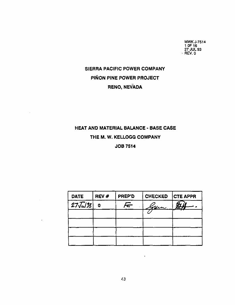
~V$K&75 14
27 JUL 93 RN.0
SIERRA PACIFIC POWER COMPANY
PlFiON PINE POWER PROJECT
RENO, NtikDA
HEAT AND MATERIAL BALANCE - BASE CASE
THE M. W. KELLOGG COMPANY
JOB 7514
43

pinon sine PO8eV FTo,ect _-_ WI *ierr, PlCIfiC POICV CmPmY PWC ~cno. llerrdr ,++i,
27-G ---
HUT u(D (UXRML MUKE - WE CASE WC0 COAL YllH 2l”C OXlOL OhSED SORBEWT
_______________________________________________----______________________---______------------------.-_____----------------_____ 1 2 I a
lDERTlFICATlOW MOlW"l&r Prepared Carl Limestmc Ash Yithdrmal Codl Tranrs Yeipht FeedstOCk Feedstock Fran Guifier Ai,?
________________________________________---------------------------------------------------------------------------------------. Ye Lblllr YtS Lb/w WI
----_-----...--....--------------------------*---------------------------------------------~---------~~!~~----------~~!~------~~ GASES:
Carbon Monoxide "ydmgen Carbon Dioxide kthmc llitmgen kgon Oxygen Inno”i. "ydmge" Sulfidc C~rbonyl Sulflde Sulfur Oioxidc Mater YapOr "ydr-qen Chloride
TOTAL WSES
28.01 2.02
41.01 16.01 28.01 39.9s 32.00 17.03 34.08 60.08 81.06 18.02 36.46
6&s Flcu. Lb Mololwr mlecular Yelght. tit.5 US YOIU~. xm b VOIU~W. scm
SOLIos: Cl&M Hydrogen w9en "ltmgcn Sulfur Chlorides kh noO(lt"R
TOTAL SOLIDS
SOR6MT: CA0 CKO3 CIS CJSM WI &Co3 l”wtl
TOTAL SORBEWT
TOT& FLOW. Lmr
16.02
68.29 4.64
12.04 1.01 0.35 0.00 9.67 1.00
____--- 100.00
56.06 100.09 72.14
136.14 40.31 84.32
HEATlRG YILW: 6as Lw. BWSCF G.mous Fuel "4". IWtulhr
46.466 3.155 6.195
667 241
6.56: 2.722
---__-- 88.045
0.00 0.00 0.00 0.00
77.99 0.90
20.82 0.00 0.00 0.00 0.00 0.29 0.00
0.04 PO.04 0.W 0.00 0.00 4.09 547
lp3.00
68.045
27.19 1.778 0.07 0.36 2: 0.22 11 0.17 11 0.00 0
72.00 4.706 0.00 0
___-- -- __--_- - 100.00 6.539
0 76.65 1.127
3.007 0.00 0 10.23 15: : 0.00 3.26 48 0
137 0.00 1% 9.M 1,: -_____- ____--- -___---
3.340 100.00 1.471
3.340 8.010
100.00
TMPERAUTURP. F so 50 $00 PRESSURE. PSIA 13 13 35s
44
Pinon Pine Porrr Project sierr, PlCifiC sorer cw4n)r Rem. "w.d.
--_ MYI. J-,$,4 / I \-
I>ELLffiG-/ Pl9t 3 of 16
Rev. 0 \Y/ 27-JUL-1993
--_ "UT AND UTERIAL BALANCE - BASE CUE
SUFCO COAL "1," 2lNC OXlOE 6ASED SORBEN ________________________________________-------------------------------------- ----.--.-----------_----.---------------------------
5 6 7 8 IvENrIFlCAlloR Nnlccvlrr Prooccss Ai? Product 64s Product 6,s . rotrl *ir Fran
Wight TO G.,ificr Fm 64sifier From cyclone G&S Turbrnc ____________________-------~--------------------------------------------------------------------------------------------~---------
VOIS Lb/ur "Oil Lb/H? "0,s Lb/W Yol* Lb,"7 ____________________-.-----~~----------------------------------------------------------------------------------------------------- GASES:
Carbon Honoxide 28.01 0.W HydrO9m 2.02 0.W Cwban Oioxfde 44.01 0.W l4eth.m 16.04 0.00 Witmpcn 28.01 77.99 Mgen 39.95 0.w OXYpe" 32.00 20.82 &lRLMi, 17.03 0.M HFdmpen Sulfidc 34.08 0.00 C,rMn)rl Sulfide 60.08 0.04 Sulfur Dioxide 64.06 0.00 nattr Y.Por 18.02 0.29 Nydm9cn Chloride 36.46 0.W
---____ TOTAL GASES 100.M)
Cal Flow. Lb nolrllnr Nnltc"lu ucwlt. Gases 0% "Ol"rn. Km h YOIW. scm
: 141.222
2.316 43.063
0 0
: 333
0 _______ 186.934
24.40 82.478 15.12 3.666 5.17 27,360 1.32 2.w2
48.03 161.870 0.55 2.643 0.00 0 0.02 33 0.03 119 0.00 22 0.00 0 5.29 11.4% 0.00 0
-.--v-m ______- 100.00 292.190
6463.5 12029.4 28.92 24.29
3167.2 L4.173.0 40.868 76.060
LlQulos: Y.tCr 16.02
SOL10S: CUbOIl 12.01 Hydmgen 1.01 o.ygcn 18.W “itrog.?” 14.01 Sulfur 32.06 Chlorides 35.45 Ash WaOiltYrt 18.02
TOTIL SaLlOS
“ta -_-e--e
64.20 0.32 0.70 0.41 0.36 0.00
44.00 0.00
32,943 197 428 248 221
0 26,742
0
100.00 60.778
SOR8EIIT: C&O 56.68 cam 100.09 CJS 72.14 crso4 138.14 40 40.31 MC03 84.32 1nertr
78.65 0.00
10.23 0.00 3.28 0.00 9.84
TOTAL SORBEWT 100.00
19.964
2.68: 0
054
2s: ____--_ 26.647
TOTAL FLOW. Lb/w lE6.934 379.01s
"EATlWG VALUE: trs LNY. 8t"lSCF GASCO"S Futl LNY. mst",hr
132 132 603.26 803.28
24.48 82.478 15.12 1.666 5.17 27.360 1.32 2.542
48.03 161.870 0.55 2,643 0.00 0.02 3: 0.03 119 0.00 22 0.00 5.29 11.4: 0.00 0
____--_ ______- 100.00 292.190
12029.4 24.29
14.173.0 76.060
___--__ 54.20 2.308 0.32 14 0.70 30
0.41 0.36 :: 0.00 0
44.00 1.872 0.00 0
__-_-__ ___-___ 100.00 4.2S4
76.65 399 0.00
10.23 5:
0.00 3.28 1; 0.04 0 9.84 $1
-______ ___ .___ 1W.W 621
296,985
0.W 0 0.W 0 0.00 0 0.00 0
78.W lS4.073 0.W 2.527
20.82 46,902 0.W 0 0.W 0 0.00 0 0.W 0 0.29 363 0.00 0
----_-- __-___- lW.W 203.945
7.051.7 26.92
8.127.9 44.587
203.94s
TDIPEPALTURE. F 660 1.600 1.600 707 PRESSURE. KM 410 345 344 la2
45

nnon Ptnc Powr Project ___ “YX J-15 *icrrr Pacific Pacr cmwnr I N \- Heno. Ncrrdr I~‘:‘~~~’
Page 4 Of *er
2?-JUL-19
HUT AR0 IUTERIAL BALM2 - MSE CASLSE SUFCO COAL YlTH ZlWC OXIDE MSEO SOR6ENT
_____e-s--s- ________________________________________------------------------------.---------------------~----------------------- 9 10 11 12
lOEnTlFlCAllON llolK”,ar RCCYCIC stem to Recycle Gas. Gas From Pmduct "eight Gas To Grid G,,, fier to Annul "I Gas Cooler
________________________________________-----------------------------------------------------------------------------------~---- VOlb Lb/N? "01% Lb/W
-------......---....------------------------------------------------------------------~~!~------~~!~~-------*--~~!~------~!~~-- G&ES:
cwtmn NonOxide Hydmgcn Clrbon OiD.xidC Nethme nitrogen Argon O"Y9M LIIIID"l. Hydmgen Sulfldc Orbony Sulfide S"lfW O‘OIIde Hater VlPO? "ydmge" Chlorldc
28.01 24.49 2.02 15.12
44.01 5.17 16.04 1.32 26.01 b0.w 39.95 0.55 32.00 0.00 17.03 0.02 II.06 0.W 60.08 0.00 64.06 0.04 16.02 5.27 36.46 0.W
109
3: 3
214 3 0
: 0 0
15 0
TOT*L WSES lW.W 367
Gas FlW. Lb Iloierltw 15.9 Nalec"l*r "eight. GdICf 24.29 Gas Yolum. ACFW 6.1 Gas YOlUne. *cm 101
LIOUIDS: Yater
SOLIDS: CUbO" Hydrogen Olype" nitmpcn Sulfur ChlLWid~S Alk Nd*t"R
TOTIL SOLIDS
SONBENT: cao C&CO3 C&S C&SO4
%3 ,ncrts
TOTAL SORBEWT
TOTlL FLOW. Lb/HP
18.02
12.01 1.01
16.00 14.01 32.06 35.45
16.02
56.06 100.09 72.14
136.14 40.31 84.32
HEATING "ILUE: Gas L"". BtulSCF G~~e~u~ Fuel LW". m6tu,Nr
367
132 0.60
100.00 16.651
_-____- ______ _ 100.00 16.651
921.3 16.02 441.2 5.645
16.651
24.49 15.12 5.17 1.32
46.06 0.55 0.00 0.02 0.04 0.00 0.00 5.27 0.00
3.079 137
1.022 95
6.042 99 0
; 0 i
426 0
100.00 10.900
446.6 24.29 171.3 2.636
10.900
132 22.46
24.46 82.1 15.12 3.6 5.17 27.3’ 1.32 2.5
48.03 161.6 0.55 2.6 0.00 0.02 0.03 1 0.00 0.00 5.29 11.1 0.00
____ ___ _ ____ lW.W 292.1
12029 24.
9.491 76.0
Ht. - - __ ___
54.20 2.3 0.32 0.70 0.11 0.36 0.00
44.00 1.6 0.00
_ -__-__ _ __ __ lW.00 4.2
76.65 3 0.00
10.23 0.04 3.26 0.00 9.E4
------_ --_-- 160.00 5
296.9
1
TMPENAnJRE. F 365 600 365 1.0 PRESS”RE. PSM 400 400 400 3
46
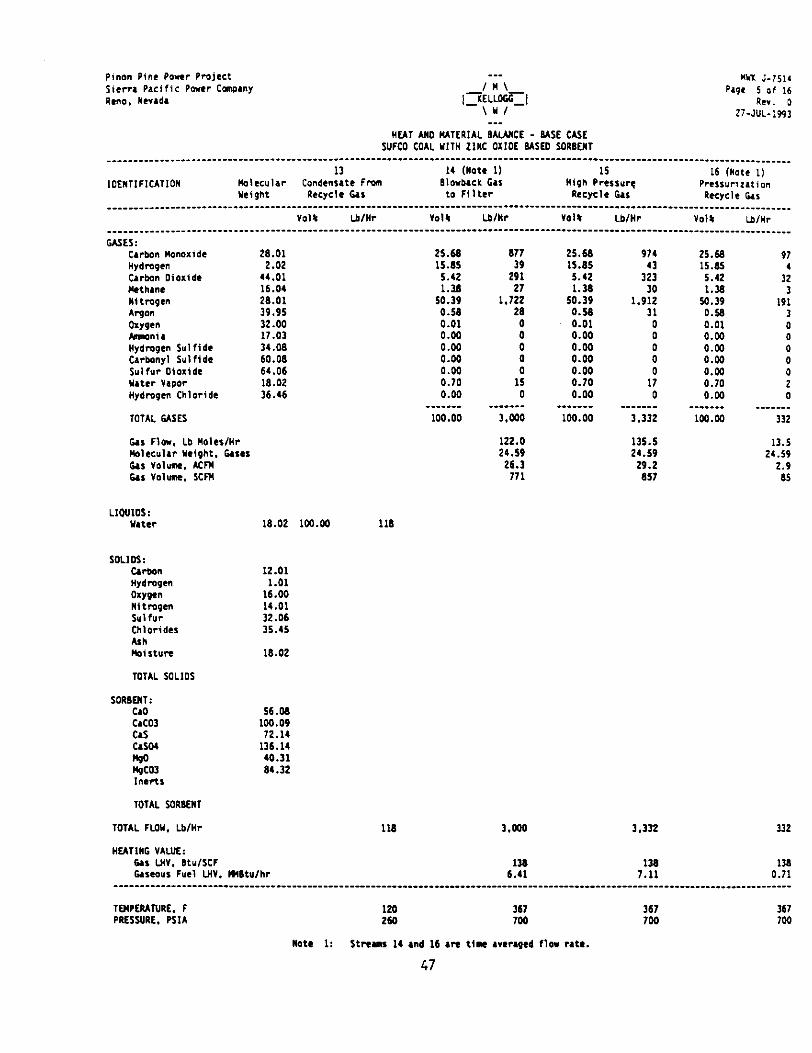
sinon Pine Porc7 Project siern Pacific Power Cmxny Rcno. Ncvrdr
___ “NX J-751‘ page 5 Of 16
RCV. 0 27-JUL-lpP3
NEAT AN0 MATERIAL 8AWtCE - BASE CASE SUFCO COAL YlTH ZINC OXlOE USE0 SORBENT
_______________________________-___________----------_-_-----_-----------------------------_-_____________________________________ 13 14 (Note 1) 15 16 (Note 1)
lOENTlFlCATlOW )lolecular Condcns.tc fm Blorbrck Gas Nigh Prcrsur( Srrll”rrz,tion YeiOht RCCYCIC G&r to filter Recrcle 6,s Rrerclc Dr
G&ES: Cwbon Monoxide Wydmgcn Carbon Dioxide I(cthmc NltrOpL" Argon OlY9c" W"i. Hydmgcn Sul fide CMmyl Sulfide S”lf”? o+mide uter “&pm “ydmgcn Chloride
26.01 2.02
44.01 16.04 26.01 39.95 32.00 17.03 34.06 60.06 64.06 16.02 36.46
“014 Lbimr “014 Lb/NT “014 LblNr "014 Lb,WI
25.66 15.65 5.42 1.36
so.39 0.50 0.01 0.00 0.00 0.00 0.00 0.70 0.00
677 39
291 27
1.722 26
i
i 0
15 0
TOTAL GASES
Gu Flow. Lb MolcslHr Nolrculrr Ycight. her Gar "0l"me. Am G&I "Olum. *cm
100.00
Lloulos: Y.tCr 16.02 lw.w 116
3.000
122.0 136.5 21.59 24.59
26.3 29.2 771 657
SOLIOS: cmbon “YdlWM Olypt” Nltmgm Sulfur ChlOddM All! lbilt”re
12.01 1.01
16.00 11.01 32.06 35.45
16.02
TOTAL YlLlOS
SORBENT: c.0 QC03 0s CA04 N-30 hgco3 1ncrtr
56.06 lW.09 72.14
136.14 40.31 61.32
TOTAL SORBENT
TOTAL FLO”. Lb/Mr 116 I.@36 3,332 332
25.60 974 15.65 43 5.42 323 1.36 30
50.39 1.912 0.58 31 0.01 0
0.00 0.00 : 0.00 0
0.00 0.70 1; 0.00 0
___ ____ _-___-_ 100.00 3.332
25.66 97 15.65 5.42 3: 1.36 3
50.39 191 0.58 3 0.01 0 0.00 0 0.00 0 0.04 0
2: 0 2
0.00 0 --__--- ____--_
lW.00 332
13.5 24.59
2.9 65
"EATIWG VALUE: Gu LN". BtulSCF Guca"S Fuel IJI". Hmwhr 61:
138 7.11
11 0.71
TMPERANRE. F 120 367 367 PRESSURE. MIA 260 7w 700
Note 1: Stream 14 md 16 are time weraged fla r.t..
47
367 7w

pinm Pine Perrr Project --- wx J-i *ierr, PlCifiC Power Cmwny Page 6 o! k”O. “mada llr..
27-JUL-I
HEAT AN0 IUTER1A.L MUI(CE - USE CASE SUFCO COAL "IT" ZINC OXIDE GASEU SORBEN
________________________________________-------------------------------------------------------------------------------------~~ 17 (Note 1) 18 19 (Note 1) 20
lOENTlFlCATlON ,b,eculrr Sorbmt legcnrr.tio" COO,& Prtsl"rirlti,on Hot "eight PrOdUCt Gas Recycle Gas *,r Recycle Gas
“0,. Lb/lb- “014 Lb/N? ------......-....-..------------------------------------------------------------------~~!~------~~!~~----------~~!~------~!~~. GASES:
Carbon "onoxide Hydrogen C,rbon Dioxide Nethanc wi trngcn Argon OXYpc" hnwnia Hydrogen Sulfide carbony, Sulfldc Sulfur Oloi‘dc “.ter YlPOP Hydrogen Chloride
26.01 2.02
14.01 16.04 26.01 39.95 32.00 17.03 34.06 60.06 64.06 16.02 36.46
0.00 0.00 0.00 0.00
96.36 0.54 0.00 0.W 0.00 0.00 1.14 0.04 0.02
_ _ -____ 1OO.W
:
i 8.722
64 0
: 0
231 0 0
-_----- 9.017
24.49 5.346 15.12 236 5.17 1.775 l.lZ 165
48.06 10.196 0.55 171
0.00 0 0.00 0
0.00 0.00 : 77.99 616
0.90 13 20.62 219
E 0
0.00 : 0.00 0 0.29 2 0.00 0
.__ __ _ _ ___ -_- - 100.00 1.060
37.4 28.92
9.8 236
24.49 5. 15.12 3.17 1. 1.32
48.06 10. 0.55 0.00 0.02 0.00 0.00 0.02 5.27 0.04
-_ _____ __-_ 103.03 18.
77 21 74 1.
TOTAL GASES
GM Flow. Lb Noleslnr 316.5 va1eC”l.r Yetgilt. Gases 28.4.9 Gu “OIum. Acm 2.917.3 a, v0hh *cm 2.002
LlQulos: uter 18.02
soLlos: cmban 12.01 Hydmgcn 1.01 oxygen 16.00 ni tmgen 11.01 Sulfur 32.06 Chlorides 35.45 AllI Pd*ture 16.02
TOTAL SOLlOS
SORI)MT: cao cac03 cas CISM 1100 4Co) l”Wt$
TOTAL SORBEN,
TOTAL FLO". LblHr 9.017 16.936
MATING VALUE: 0, LN". BtulSCF Gaseous Fuel L"". H4BtuIhr
132 39.06
0.00 0 0.02 2 0.00 1 0.00 0 0.00 5.27 74: 0.00 0
_ __ ___ _ ___ _ ___ 100.00 16.936
779.7 24.29 378.9 4.930
1.064 16.
39
TMPERANRE. F PRESSURE. All
1.342 270 120 1. 36 270 395
Note 1: Strems 17 And 19 AR tint Lvcragcd flow rates.
48
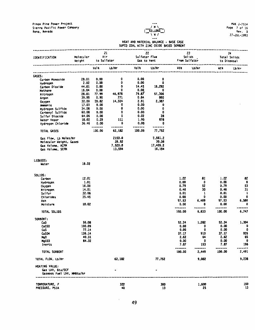
Pinon Pine Power Qrojcct --_ Yyx J-7511 S,cr,, Pacific Power CWW /M\ QlPL I 0‘ 16 Reno. IIc*.*. hr. 0
2?-JUL-1993
HEAT A”0 MATERIAL 6ALAIICE - USE C&E SUFCO COAL “IT” ZlRC OIlDE BASE0 SOR6ERT
___________----- ________________________________________----------------------------------.--------------------------------------- 21 22 23 24
IOENTIFICATIOW MOlKUlar Air Sulfrtor Flue SOlidS Tot.1 SOlidS Yeipht to Sulfator Gas to "CM Fmm Sulf& to 0ilP0s.l
__________------ ____________________---------------------------------------------------------------------------------------------- YOl4 Lbtnr "014 Lb/W ut4 LblWr Yt4 Lb/k
____________________---------------------------------- --_________--___________________________------------------------------------
USES: CIrb.2” “onaxide 26.01 0.W Hydrogen 2.02 0.00 Clrbo" oioxl*e 44.01 0.00 "cth.nr 16.04 0.00 Il,tmqen 26.01 77.99 Argon 39.95 0.90 OXY9M 32.w 20.62 hnm"l~ 17.03 0.04 "ydmgrn Sulfide 34.06 0.00 Cwbonyl Sulflde 60.06 0.04 Sulfur Oloxidc 64.06 0.M) u.ter Ylwr 18.02 0.29 Hydmgcn Chloride 36.46 0.w
_______ TOTAL WSES 100.00
OS Flew. Lb llo1cr/tlr k?,ec"lrr Yelght. c*ses 6ar YOlUnn. Asm 6as volume. scm
0 0
: 46.976
171 14.324
: 0 0
111 0
.-_---- 62.162
2150.0 2.661.2 26.92 30.16
7.520.6 17.405.2 13.564 16.194
LIQUIDS: ".ter 16.02
soLIos: CWbUtl 12.OI Hydrogen 1.01 OlY9M 16.00 "‘tmqen 14.01 S”lfW 32.06 Chlorides 35.45 Ash IlO‘ltUrQ 16.02
TOTAL SOLIOS
fORBENT: cao 56.00 Cd03 100.09 C&S 72.11 MO.4 136.14 MO 40.31 &CO, 66.32 ,nertt
TOTAL SOR6EHT
TOTAL FLOW. Lb/W 62.162
HEAWG VALUE: 6u Lw. 6tulSCF Gllc0"1 Fuel WV. QMBtulhr
0.00 0.00
14.46 0.00
79.6i 0.64 2.91 0.00 0.00 0.00 0.02 1.90 0.00
____ __ - 100.00
0
16.29~ 0
57.306 6bO
2.367 0
:
6;: 0
- __ _ __ - 77.752
1.22 0.00 0.79 0.46 0.01 0.00
97.53 0.00
100.00
62.34 1.262 0.00 0 0.00 0
31.11 910 2.62 64 0.04 0 1.61 193
--__-__ -_____- loQ.00 2.449
l?.ISL
61 0
:i 1
6.46: 0
._____- 6,633
9.082
I.22 62 0.00 0
0.79 0.46 :: 0.01 0.00 ;
97.53 6.W 0.00 0
___--__ - -_____ 1w.w 6.147
62.34 1.304 0.00 0 0.00 0
37.11 626 2.62 65
0.00 7.111 19: _-_-_ - ____ _-_
m3.m 2.191
9,236
TMQERATVRE. F 322 300 I.600 150 QRESSURE. PSIA 40 13 26 13
49

~inon Pine Poe? Q~~jcct sirrr, QKifiC Qacr Ccmpany Rcno. Nevada
--- WI: J-, Qqc 6 ot
hr. 2?-JUL-I
“UT bM0 PATE6,A.L 6AUllCE - MSE CASE SUFCO COAL Y,," 2,"C OXIDE USED SORBEM
IDERlIFICATIDW 25 26 27 26 IlIote 1,
HO,.X",~V Cyclone Fines Product Gas to Product G1, Fr.(m Rcgcnerrtion Ai? t "eight to hrifiw Sorbat RuCtDrl sorbcnt Relcton Sorbcnt Reutor
____________________------------------------------_______________________------------------------------------__________________ ml; Lb/k- “0,s Lb/w VOll Lb/W VOl4 LblHV
WES: Carbon "onoxide Hydm6en Carbon Dioxide Methmc “ItmgCn Argon Ol.Ypl hwni. "ydmgen Sulfide Urbony, Sulfide Sulfur Dioxide Yltw vwor Hydmgm Chloride
28.01 2.02
44.01 16.04 28.01 39.95 32.00 17.03 31.06 60.06 64.06 16.02 36.46
TDTAL GASES
0.00 0 5.24 11.473 0.00 0
--__--_- --__--_ 100.00 295.191 100.00 295.132
6.1 F,o*. Lb "o,es,"r 12.lSI.O 12.151.0 Ilo,ecu,,r Yclght. Glsu 21.30 24.29 6as volume. Km 9.690.5 11.026.a Gas YOlUme. scm 76.632 16.032
LIDDUIDS: mter 16.02
SOLIDS: CWbOn 12.01 Y.20 Hydm6en 1.01 0.32 oxygen 16.00 0.70 Il,tmgcn 14.01 0.61 S”lfW 32.06 0.36 Fide= 35.65 0.w
41.w no, S”R 18.02 0.00
_ ____ __ TOTAL SOLIDS 100.W
SDR6MT: c1D 56.06 76.65 caco3 100.09 0.00 C.S 72.11 10.23 Cd04 136.14 0.W
zo3 40.31 64.32 3.26 0.00 ,nc*s 9.84
30.637
:i 231 206
0 26.671
0 --_____ 56.526
19.565
2.61:
83; 0
2.513
24.49 15.12 5.17 1.32
66.06 0.55 0.00 0.02 0.00 0.00 0.00 5.27 0.00
63.355 3.705
27,666 2.569
163.592 2.671
3: 6 0
11.53; 0
TOTAL SORKIT
TOTAL FLOY. Lb/W
100.00
"EAT,"6 YALUE: 6as LHY. BWSCF ~ILo"I FW, LHY. m8t"lhr
25.526
62.060 295,191
132 132 609.69 666.11
295.132
0.W
Ki 0.W
76.W 0.90
20.62 0.W 0.00 0.00 0.W 0.29 0.00
--_. lw.w
1.730 l.WO 1.001 3u 330 290
Note 1: Flew r,te dmotu intcmdi,tc r.,ue and *ill be conflmed Irtcr.
50
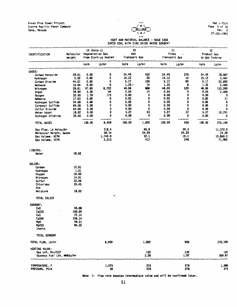
Qinon Pine QOWV Project ___ “YX J-?Si. sierra QIC, tic Power CmwllY
,“LM)+ Qwc 9 of 16
9cno. “W,d. RC”. 0 2?-JUL-1993
___ HFA? MD )(ITERIAL 6AUllCE - WE CASE
SUFCO CDAL YllH LINE OXIDE MSCD SORBEN ________________-------------- __._____________________________________-------------------------------------.---~-~---------------~
29 wtc 11 30 31 32 1OEnTlFlCATlOW Yalecul4r b!nJeneratlOn 0% Ash Fines Product Dr
IkiQflf Fm Start-"Q "utcr rrmswrt tr, TrwwOrl tis to 6M Turbine
CASES: Cwbon wanoxide 26.01 0.m Hydmqcn 2.02 0.00 C,rbon Dloiide 44.01 0.m Rth,nc 16.01 0.W “ltmgcn 26.01 97.0 Argon 39.95 0.50 oxygen 32.00 1.70 hlmnir 17.03 0.00 Hydrapen Sulfidr 34.06 0.00 Carbonyl Sulfidr 60.06 0.W Sulfur Dioxide 64.06 0.w b!.ter "IpOr 18.02 0.W Hydrogen Chloride 36.46 0.W
_------ lOTAL GASES iw.00
6.~ Fin. Lb Moles/W Wolccullr weight. 6urr Gas "Olme. Am 6at volume. scm
:
: 6.722
64 173
0 0 0 0 0 0
_____-- 6.959
316.4 26.16
1.719.9 2.013
LIQUIDS: uter 16.02
SOLIDS: CWbM Hydm9en OXyQcFl “ttmQm SUlfW Chlorides Ash Ai*twe
7OTAL SOLIDS
12.01 1.01
16.00 11.01 32.06 35.45
16.02
SDRBEIT: C&O 56.06 CICW lW.09 C&S 72.14 CISM 136.14 ;b3 64.32 40.31
l”.VtS
TOTAL SOR6W
TOTAL FLO". Lb/W 6.959
HFATlYG "AL"E: bls UN. BtufSCF 6,r.?ous Fuel LH". Q946tulhr
24.49 452 15.12 20
5.17 150 1.32-
46.06 .9i 0.55 14
E :
0.00 0.00 i
0.00 5.27 6: 0.00 0
_ ___ __ _ - _____ _ 100.00 1.602
66.0 21.29 32.1
417
1.602
132 3.30
24.49 270 15.12 I2 5.17 09 1.32 8
46.06 529 0.55 0.00 El 0.02 0 0.00 0 0.00 0 0.00 5.27 3; 0.00 0
--_---- _-_--_- 100.00 955
39.3 21.29
19.1 248
955 276.190
132 132 1.97 569.67
24.19 24.19 76,OOl ?6.m? 15.12 15.12 3.467 3.467 5.17 5.17 25.892 25.892 1.32 1.32 2.404 2.404
46.06 46.06 153.094 153.094 0.55 0.55 2.500 2.500 0.00 0.00 0 0 0.02 0.02 31 31 0.00 0.00 6 6 0.00 0.00 0 0 0.00 0.00 0 0 5.27 5.27 10.791 10.791 0.W 0.W 0 0
------- ------- _____-- _____-- lw.m lw.m 276.190 276.190
11.372.0 24.29
10.869.3 71.902
TMPERAV"RE. F PRESSURE. QSiA
1.075 270 270 so 270 270
“ate 1: Flor rate demote, Intemedlrt~ value ,nd rlll be conf1m.d later.
51
l.mO 271
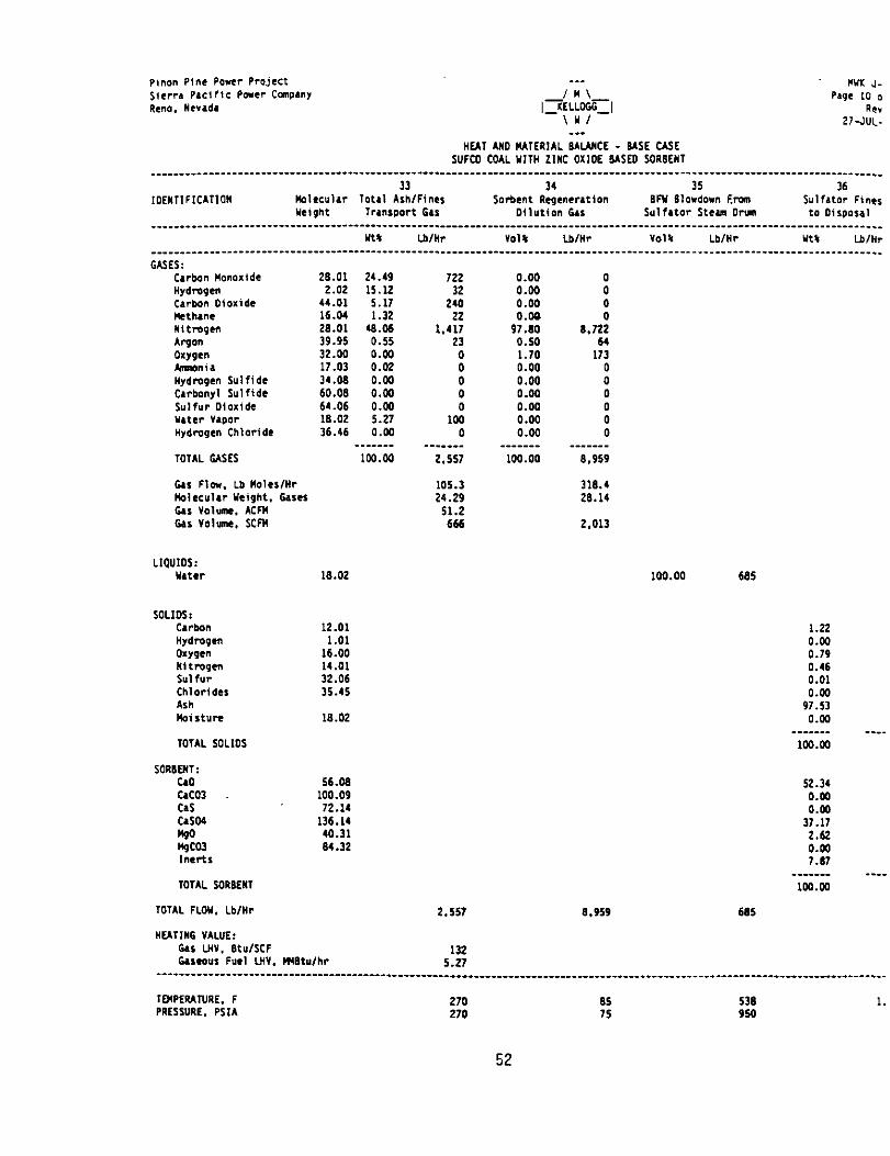
~inon Pine Power Project _-_ wx J- sierr. PICI‘IC Power ConPrnY sage 10 0 Rem. “Cad. RC”
27-JUL-
"EAT A"0 IUTERIAL W-A"CE - EASE CASE SUFCO COAL YlTH LlWC OXIDE MSED SORBEWT
_________________________________--___________---.-------_____________________________________________________________________ 33 34 35 36
IDEHllFlCATlOW Mlccular Total Ash/Fines *orbent llcgenerrtion BN BlOldD"" Ercm Sulfrtor Fines weight TrlnfpDrt tu Dilution Gas Sulfrtor steun orun to oi lPDI.1
______________---------------------------------------------------------------------------------------------------------------- !a* lblklr "019 wnr "Olfl Lb/H? Ytl Lb,"7
____________--------------------------------------------------------------------~-------------~----~-------------------------~ GASES:
Carbon Hanoxide 28.01 Hydrogen 2.02 Carb-aon Oioxlde 44.01 Htttunc 16.04 Ilitmgcn 28.01 Argon 39.95 oxygen 32.00 Mmonir 17.03 Hydrogen Sulfide 34.06 Carbonyl Sulfide 60.08 Su,fur Olo,.ide 64.06 uter "apor 16.02 Hydrogen Chloride 36.46
TOTAL USES
6.1 Flew. Lb ltolcr/Hr bblec~lw Might. Gaser 64~ v0hk Acm C*S v0hh scm
LIQUIOS: uter 18.02
SOLIOS: carbon 12.01 Hydrogen 1.01 oxygen 16.00 "ltmgen 14.01 Sul fur 32.06 Chlorides 35.45 AdI MistuPc 18.02
TOTAL SOLIDS
SOR6MT: cao cac03 CAS OS04
$3 ,nel-h
TOTAL SORBEMI
TOTAL FLOY. Lb,"r 2.557 6.959
HEATlllG VALUE: 6.1 I."". BtufSCF 6asco~s Fuel L"V. ,Mtu/hr
132 6.27
------------------------------------------------------------------------------------------------------------------------------~
TMPERATURE. F 270 85 530 1. PRESSURE. PSIA 270 75 950
52
24.49 122 15.12 32 5.17 240 1.32 22
46.06 1.417 0.55 23 0.00 0 0.02 0 0.M) 0 0.00 0 0.00 5.27 1; 0.00 0
_ __ _ __ _ _._ ___ lW.W 2.557
105.3 24.29
51.2 666
0.00 0.00 0.00 0.00
97 .*o 0.50 1.70 0.00 0.00 0.04 0.00 0.00 0.00
0 0 0 0
6.722
1;: 0 0 0
i 0
100.00 8.959
318.4 26.14
2.013
100.00 605
1.22
i:! 0.46 0.01 0.00
97.53 0.04
_ _ _____ _ ___ io0.m
52.34 0.00 0.00
37.11 2.62 0.00 7.67
_______ ---- 1W.W
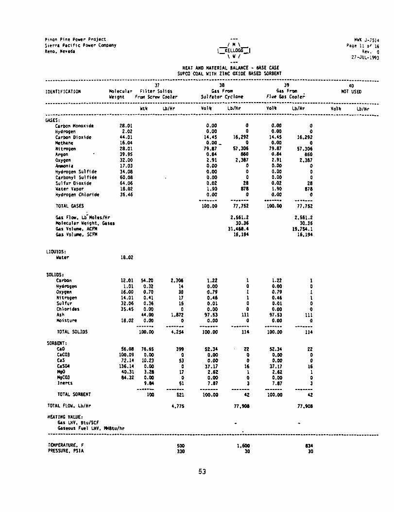
pinan Pine Power Project sicrr. Pacific POrCr Cmlwly Rem. rcrrdr
--- *UK J-7514 /M\
J~ELL'Iz%~I page ii Of ,6
hr. 0 \Y/ 27-JUL-19%
HEAT AND MTERlAL BALANCE - 6ASt C&E WC0 COAL Y,," 21°C OXlOE BISm SORBEM
____________________----------------~------------------------------------------------.-------------------------------------.------ 37 3a 39 40
,oE”TlFlC*TlO” P0lec"l.r Filter SOlid, G&I Fran 64s From YCigllt F-on Screw Cooler Sulfrtor cyc1onc Flue krr Caolei
No1 USED
____________________-----------------------------------------------------------------.-------------------------------------------- Ytt Lb/W vo1* LbIWT volt Lb/w va1)r tb/Yr
O\SES: carbon “000ZidC Hydrogen Carbon Dioxide !!.a.nc "ltmgen APgO" oxygen hmmia Hydrogen Sulfldc C4rbonyl Sulfidc Sulfur Oioxtde Mater vapor Hydmgcn Chloride
TOTAL OASES
6.1 Fla. Lb-Moles/W mlcculrr "eight. CIsrs G&l v01um. ACrn US ~01~. scm
2a.01 2.02
44.01 16.04 28.01 39.95 32.00 17.03 34.08 60.08 64.06 la.02 36.46
0.00 0.00
14.45 o.oo.-
79.a7 o.a4 2.91 0.00 0.00 0.00 0.02 1.90 0.00
_-_.___ 100.00
0 0
16.292 0
57.306 860
2.3a7 0 0 0
2a a7a
0 _____-_
77,752
0.00 0.00 i 14.45 16.292 0.00 0
79.a7 57.306 0.04 a60 2.91 2.307 0.00 0
0.00 0.04 :
0.02 1.90 8:: 0.00 0
mm---.- _--____ lOO.OO 77.752
2.561.2 2.5Kl.L 30.36 30.36
11.46a.4 19.754.1 16.194 16.194
LIQUIOS: mter la.02
SOLIDS: CIrbon Hydrogen oxygen “ltmge” Sulfur Chlorides ASI! mrstwe
12.01 54.20 1.01 0.32
16.W 0.70 14.01 0.41 32.06 0.36 35.45 0.00
44.oo la.02 0.06
2.306
:: I7 ii 0
1.872 0
1.22 0.00 0.79 0.46 0.01
9;:: 0.00
TOTAL 5nL3OS lW.Do
SORaMT: C40 QC03 Cd cd24 40 mco3 Gcns
56.00 16.65 100.09 0.00 72.14 10.23
136.14 0.M 40.31 3.2) 94.32 0.04
9.a4
TOTAL SORaE", _____._
1W
TOTAL FLOW. Lb/W
"EATIWG VALUE: 6.1 UIV. BtulSCF Gaseous Fuel LHV. matulhr
4.254
39s
5: 0
17 0
51
100.00
52.34 0.00 0.00
37.17 2.62 0.00 7.a7
1 0 1
i 0
111 0
--e--m. 114
22
i 16
: 3
521
4.775
loo.00 42
77.9oa
1.22 1
E 0 1
0.46 0.01 : 9;:: 111 0
0.00 0 -_---_- ---___-
100.00 114
52.34 22
E i 37.17 16
2.62 1 0.00 0 7.a7 3
_---___ -_.____ 100.00 42
77.90
TMPEPAME. F PRESSURE. PSIA
1.644 30
a34 30
53
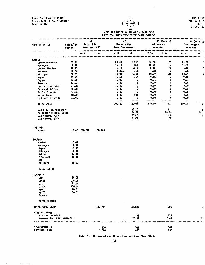
pinon PI~C Ponr Project --. NIlI. J-75, *icrn PLClfiC Pacr CcwhY Rem, "cradr ,~~L;++
Page 12 Of 1 FCC".
*7-JUL-I99
“EAT AN0 IUTERIAL 6ALbNCE - 6As.E CASE WC0 COAL "IT" ZINC OXIDE USED SORIIENl
41 42 43 (Note 1) 11 (Note 1) IOENTIFICATIOW IloleC"lar tota, 6N Recycle car AllI newer Flnel HOppCr
"eight Frm sec. Boo Fmm Ccwrc~sor "CM 0.1 lent 6.l ________________________________________-----------------------------------------------------------------------------------------
"0,s Lmr "01% Lb/w YOIS wnr Yolt Lmr ________________________________________----------------------------------------------------------------------------------------- GASES:
carbon No".lidC nydmgen C,rbm oioridc Hettunc "i *Inpen Argon OXYWn hlmn,. Wgdmgen Sul fide CIr~nyl Sulfide Sulfur Oiaide YItLr VapDr "ydmgcn Chloride
TOT*L CASES
c&s Flea. Lb Nolcr/Nr Mlcculrr Ntight. 6aser 0, volume. Am trs "Olumt. SUN
LIOUIOS: u.tw
c,rbon Hydrogen w9cn “ltmgen *"Ifur Chlorides Ml Pbisturc
TOTAL SOL105
SORBENT: CA0 cd03 CA* CISM up H&O3 l"CRI
TOTAL SORBCWT
TOTAL FLoN. Lb/HI
28.01 2.02
44.01 16.04 26.01 39.95 32.00 17.03 34.06 60.06 64.06 16.02 36.46
16.02 lW.00 130.764
12.01 1.01
16.W 14.01 32.06 35.45
16.02
56.06 100.09 72.14
136.11 40.31 64.32
130.764
24.49 15.12 5.17 1.32-
46.06 0.55 0.00 0.02 0.00 0.00 0.00 5.27 0.00
_____-- 100.00
3.652 162
1.212 113
7.166 117
0 1
: 0
505 0
_-__--- 12.929
532.3 24.29 203.1 3.366
12.929
132 26.67
25.M 59 15.85 3 5.42 20 1.36 2
50.39 115 0.58 2 0.01 0.00 : 0.00 0.00 0” 0.00 0 0.70 1 0.00 0
.___-__ - -___ __ 100.00 201
6.2 24.59
1.6 52
25.U 15.65 5.42 1.36
50.39 0.54 0.01 0.03 0.53 0.W 0.00 0.70 0.00
-_-_--- 106.66
?
___--. 1:
5 24.
1
201
TMPEUNRE. F 230 355 367 PRESSURE. PSIA I.000 400 700
not.?: 1. Stram, 43 and 14 .n time rrtr.6ed fla rates.
54
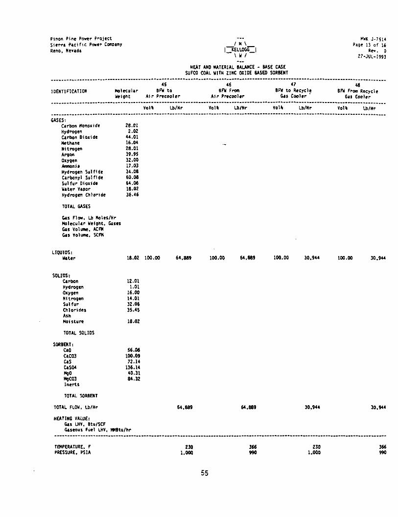
sinan Pine Power Project -__ mx J-IS,‘ sicrrr PLCiflC Power ConPuv / * \- P49C 13 of 16 Rcno, Nerrdr IQ;L;~-I PC". 0
27-JUL-1993 -__
HUT UIO MATERIAL 6AUWCE - M5E CASE WC0 COAL Y,," 2,WC OXIDE USE0 SORIICNT
____________________--------------------------------------------------------- ----------------------------------------------------~ 45 46 47 49
IOENTlFlCATlON lla,ccv,rr 9N to 9N Fran Ai?- *Rc001Cr Air Prrcoolrr
9M to I\CCYCl$ 6N From R.xycle Ndgnt firs Cooler iill Cooler
________________________________________----------------------------------------------------------------------------.----.-------- YOI% Lww "01. Lwlr VOlS Lb/W VOl* Lb/Nr
____________________----------------------------------------------------------------------------------~------------------.-------- GGES:
C,rbon Nonoride 26.01 "ydmgcn 2.02 cartmn oiolide 44.01 Netllmc 16.04 Nitmgc” 26.01 Argon 39.95 oxygen 32.00 Ammir 17.03 Hydmgen Sulffdr 34.06 Carbony Sulfidc 60.06 Sulfur Oioxlde 64.06 u.ttr war 16.02 "ydrogen Chloride 36.46
TOTAL ME5
Gas Flow. Lb no1es/wr Mlccvlrr Weight. her Gas YOlunn. Am Gas YOl"me+ *cm
LlrpJIos: utcr 16.02 1w.w 64.889 100.00 64.03 100.00 30.944 100.00 30.944
SOLIDS: carbon 12.01 "Ydrogen 1.01 oxygen 16.00 Nitrogen 14.01 Sulfur 32.06 ::Ydes 35.45
Milt”re 19.02
TOTAL SOL3DS
SOR9QlT: C&O cam c4s cm4
Eo3
56.66 100.09 72.14
136.14 40.31 64.32
TOTAL SORINT
TOTAL FLOW. Lb/M 64.669 64.899 30.944 30.944
NfATlNG VALUE: 0s LN”. Bt",SCF Gascour Furl LH". HIR",hr
-----------------------------------------------------.----------.-----------------------------------------------------------------
IMPCRATURE. F 230 366 230 366 PRESDRE. KM l.wO 990 1.000 994
55

pinm Pine Power Pmjcct -__ WYX J-751 sicrrr PKffiC P0.W CcmPanY /N\
I>ELLOCtl?l Page 14 0‘
llcno. “Wld. RC" \YI ZI-JUL-19 ___
"EAT I)(0 NATERML EALANCE - BISE CASE WFCO COAL Y,," 2,"C OXIDE BISEO SORBENT
______________________________________-_-----------_______--___-_____________________---.---------------------___________________ 49 50 (Note 1) 51 52 (Note 1)
IDENTIFICATION mlcculrr NOT USED Net Stem From Product "et stem Frml $ulfrtor Net Stun, Frm YCipht 64% Trim Cooler stc&m Drum Product 6.S COOlC
________________________________________--------------------------------------------------------------------------------------- “01% Lb/NV Yol* Lb/NT YOllr Lb/nr Yolt Lb,NV
________________________________________--------------------------------------------------------------------------------------.- USES:
carban Nmoxide 28.01 “ydrogcn 2.02 Cubon O~oxide 44.01 P!dhl”C 16.04 Nitm9t" 26.01 Al-p 39.95 0.ypen 32.00 hmonir 17.03 Hydrogen Sulfide 34.0s cwbony1 S"lfld.2 60.06 Sultur Oioxide 64.06 uter YlPOr 16.02 100.00 0 100.00 34.246 lW.W 93.8 Hydmgcn Chlorldc 36.46
TOTAL GLsE5 _-____ ____-__ ---____ ____-__ _______ _____
100.00 0 100 34.246 *oo.w 93.6
6as Flw. Lb Moles/W 0.0 1.901.0 5.207 m1ccu1rr weight. tircr 16.02 16.02 1.5. Gas VOlUnn. ACFN 0.0 357.1 976 as VOlunn. SCFN 0 12.020 32.9
SoLlos: carbon Hydropen O*lgt” Nftmgen Sulfur Chlorldel Ash Moisture
16.02
12.01 1.01
16.00 11.01 32.06 35.45
16.02
56.66 100.09 72.14
136.14 40.31 64.32
TOTAL SORNENT
TOTAL FLOY. Lb,Nr
NEATlNG VALUE: as LN". 6tulSCF G.leoW Fuel LNY. m6t",hr
34.246 93.8
TEMPERATURE. F PRESSURE, PSM
536 5 950 9
Note 1: Thts 41 total stem, production frm E-401 and E-603. Lxt split 1% to be determined upon cnplctlon of .I, hnt md mterlal balmce case,.
56

APPENDIX 5
PHOTOGRAPHS OF EXISTING TRACY FA=

Aerial photograph of Tracy Power Station looking west with 120/345 KV switchyard in foreground.
62

Existing Tracy steam electric generating Units No. 1 through No. 3 (from right to left). Photo looking North.
Existing steam electric units. Photo looking southeast across cooling pond for Tracy Units No. 1 & No. 2.
63

Existing 120 KV switchyard for Units No. 1 (right) through No. 3 (left). Photo looking north.
;-- ss.-
F . . . 2,3&*: :&y-q+--- ~~ .*&
,Ir;+.zs,-&: “‘“T&J ..--*
7rTw-Y Iry-,‘.’
.c ,~. -’ .I. ‘;‘-.J-.-, - - :::e*i- -.
+.-
_,. ;*m. . vgzz d-‘., .;.;
?$qJ$ . . : .; :-.- .;.‘j) : % - :*-I
. ‘~ 3 *F , , 3%. - ... ; v;i’ .c r
,2;. ’ I...
.d
-- Lib .., ,‘$a .‘% - . .._ .. ,A
Cooling tower for Tracy Unit No. 3. Photo looking southwest from top of Unit
No. 3.
64
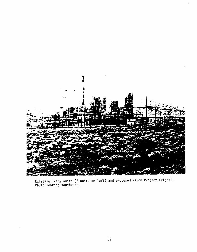
Existing Tracy units (3 units on left) and proposed Pinon Project (right). Photo looking southwest.
65