
Piezomechanik Product range Low 2017:Piezomechanik ... · Selecting a proper actuator Guideline:...
28
Low Voltage Piezo Actuators Product range and technical data
-
Upload
trinhhuong -
Category
Documents
-
view
220 -
download
0
Transcript of Piezomechanik Product range Low 2017:Piezomechanik ... · Selecting a proper actuator Guideline:...
Low Voltage Piezo Actuators
Product range and technical data

© All pictures, photos and product descriptions ar the intellectual propertyof Piezomechanik Dr. Lutz Pickelmann GmbH.Utilisation and copies by third parties have to be authorized.All rights reserved.

1. Stack types piezo actuators
1.1 Low voltage actuators with preloaded casings VS 6
1.2 Piezocartridges: Low voltage actuators in casings with front mount threading 12
1.3 Low voltage electrostrictive stacks 16
2. Ring actuators (stack type hollow cylinders)
2.1 Low voltage ring actuators: Bare ring actuators (without casing) 18
2.2 Low voltage ring actuators with internally prestressed casings VS 20
2.3 Electrostrictive low voltage ring actuators 22
3. Accessories 3.1 Electricals 24
3.2 Mechanics 24
3.3 Optic adaptors for ring actuators 25
3.4 Screw-in front adaptors SE (for stacks with casings VS) 25
3.5 Piezo-stacks PSt 150/HPSt 150 (osi-type) 26
Contents
PIEZOMECHANIK

Selecting a proper actuator
Guideline: The main pre-requisite for selecting suitable piezo components is the precisedefinition of the needed operation profile by the user!Any supplier of piezo-mechanical components will highly appreciate precisespecifications of the requested components beyond “the system shall do as muchas possible”.Putting definite numbers on the needed piezo-parameters is helpful to avoid over-sizing and mismatch. Poorly selected system components are ineffective andtherefore expensive.
Please try to analyze the needs for operating your mechanics successfully according tothe following:
A, what shift/stroke shall be achieved?B, what force variation shall be generated by the piezo action?C, what static preload is acting on the actuator from the beginning?
D, what is the desired maximum operation frequency?E, what is the desired stroke at maximum frequency (D)?F, what is the desired max. frequency at maximum stroke (see A)?G, shortest achievable rise-/fall-time?H, what external masses shall be attached to the actuator?
A, to C, allow an actuator selection for low dynamic operation accordingD, to H, aims for the best match for the designated dynamic operation.
Selecting the amplifierThe above selection process results in a piezo-actuator of distinct voltage range and electricalcapacitance. Only amplifiers with a matched voltagerange should be considered for use.Do not use amplifiers providing higher voltage!
The dynamic operation profile D, to H, defines theneeded current levels (Ipeak and Iaverage).When the power consumption of the actuatorexceeds the Watt-range, self-heating of the piezo-ceramics can occur.See brochure: First Steps towards Piezoaction
PIEZOMECHANIK
For details see brochure:“First Steps towards Piezoaction”
First Steps towards Piezoaction
Thermograph of a dynamically operated piezo stack

PIEZOMECHANIK
General comments
Low voltage stacks: Co-fired multilayer actuators (CMA): also called“monolithic” stacks, involve no gluing, but a hightemperature sintering of the complete ceramic electrode pile.Rectangular cross sections are typical due to theease of cutting processes in production.
Ring actuators: A stack with center bore: made with rings instead of discs.
Actuators with integral preload:PIEZOMECHANIK offers all kinds of piezostacks ina cased version with internal preload.The standard preload shows forces of about 10 - 20% of the maximum load. This design covers a very wide range of applications.Preloaded actuators with casings are much morerugged than the bare ceramic stacks and are morelikely to withstand “rough” handling and operation,or the impact of other environmental influences.
On request, PIEZOMECHANIK provides actuatorswith increased preload levels up to symmetricallyacting push-pull arrangements withregard to the force balance.
Dynamic operation:The real operating frequency of a piezomechanicalsystem is usually held far below the actuator’s reso-nance frequencyAsk for special low capacitance low voltage actua-tor’s PSt150hTcFor high dynamic applications● To reduce power consumption● To reduce self-heating
Do not misinterpret catalogue data:Not all operating specifications can be realized atthe same time due to simple physical facts.
● Maximum displacement/shift/stroke andmaximum force generation /max. blockingforce cannot be generated at the same time,only either-or.
● The maximum actuator shifts (strokes) shown in data sheet are only valid under constant loadconditions (no force variation! ).
● Two values for stroke are stated in the data sheetA, for unipolar activation 0 V /+UmaxB, for semibipolar operation -Umin /+UmaxThe semi-bipolar operation increases the open-loop stroke of a stack by 20 - 30%.Any kind of stack actuator is suitable for semibi-polar operation at room temperature.
Max. Voltage range: -30 V thru + 150 VData set for stroke shows 2 values: A / B A: Unipolar operation 0 V/+150 VB: Semi-bipolar operation -30 V/+150 V
Example:Piezostack PSt 150/7/20 VS 12Unipolar operation 0 V/ +150 V: stroke 20 µmSemi-bipolar operation -30 V/+150 V: stroke 27 µm
6
Standard configuration:
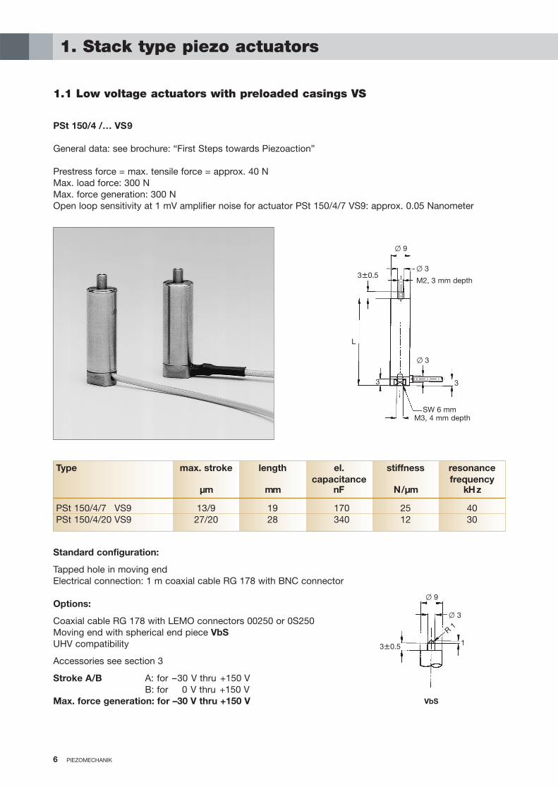
Tapped hole in moving endElectrical connection: 1 m coaxial cable RG 178 with BNC connector
Options:
Coaxial cable RG 178 with LEMO connectors 00250 or 0S250Moving end with spherical end piece VbSUHV compatibility
Accessories see section 3
Stroke A/B A: for –30 V thru +150 VB: for 0 V thru +150 V
Max. force generation: for –30 V thru +150 V
6 PIEZOMECHANIK
1. Stack type piezo actuators
1.1 Low voltage actuators with preloaded casings VS
PSt 150/4 /… VS9
General data: see brochure: “First Steps towards Piezoaction”
Prestress force = max. tensile force = approx. 40 NMax. load force: 300 NMax. force generation: 300 NOpen loop sensitivity at 1 mV amplifier noise for actuator PSt 150/4/7 VS9: approx. 0.05 Nanometer
Type max. stroke length el. stiffness resonancecapacitance frequency
µm mm nF N/µm kHz
PSt 150/4/7 VS9 13/9 19 170 25 40PSt 150/4/20 VS9 27/20 28 340 12 30
1
� 9
� 3
R 1
3�0.5
VbS
� 9
� 3
M2, 3 mm depth3�0.5
L
3
� 3
SW 6 mmM3, 4 mm depth
3
7PIEZOMECHANIK 7
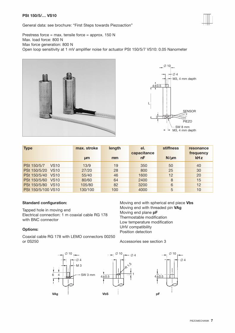
PSt 150/5/… VS10
General data: see brochure: “First Steps towards Piezoaction”
Prestress force = max. tensile force = approx. 150 NMax. load force: 800 NMax force generation: 800 NOpen loop sensitivity at 1 mV amplifier noise for actuator PSt 150/5/7 VS10: 0.05 Nanometer
Standard configuration:
Tapped hole in moving endElectrical connection: 1 m coaxial cable RG 178with BNC connector
Options:
Coaxial cable RG 178 with LEMO connectors 00250or 0S250
Moving end with spherical end piece VbsMoving end with threaded pin VAgMoving end plane pFThermostable modificationLow temperature modificationUHV compatibilityPosition detection
Accessories see section 3
Type max. stroke length el. stiffness resonancecapacitance frequency
µm mm nF N/µm kHz
PSt 150/5/7 VS10 13/9 19 350 50 40PSt 150/5/20 VS10 27/20 28 800 25 30PSt 150/5/40 VS10 55/40 46 1600 12 20PSt 150/5/60 VS10 80/60 64 2400 8 15PSt 150/5/80 VS10 105/80 82 3200 6 12PSt 150/5/100 VS10 130/100 100 4000 5 10
� 10
� 4M3, 4 mm depth
4�0.5
L
3
SENSOR
SW 8 mmM3, 4 mm depth
PIEZO
SW 3 mm
� 10
� 4
M 3
6
VAg
1
� 10 � 4
R 1.5
4�0.5
VbS
� 10
� 4
4�0.5
pF
4

88 PIEZOMECHANIK
PSt 150/7/… VS12
General data: see brochure: “First Steps towards Piezoaction”
Prestress force = max. tensile force = 300 NMax. load force: 1800 NMax. force generation: 1800 NOpen loop sensitivity at 1 mV amplifier noise for actuator PSt 150/7/7: 0.05 Nanometer
Standard configuration:
Tapped hole in moving endElectrical connection: 1 m coaxial cable RG 178with BNC connector
Options:
Coaxial cable RG178 with LEMO connectors00250 or 0S250
Moving end with spherical end piece VbSMoving end with threaded pin VAgMoving end plane pFThermostable modificationLow temperature modificationUHV compatibilityPosition detection
Accessories see section 3
Type max. stroke length el. stiffness resonancecapacitance frequency
µm mm µF N/µm kHz
PSt 150/7/7 VS12 013/9 19 0.7 120 40PSt 150/7/20 VS12 27/20 28 1.8 60 30PSt 150/7/40 VS12 55/40 46 3.6 25 20PSt 150/7/60 VS12 80/60 64 5.4 15 15PSt 150/7/80 VS12 105/80 82 7.2 12 12PSt 150/7/100 VS12 130/100 100 9 10 10PSt 150/7/120 VS12 160/120 118 11 8 8PSt 150/7/140 VS12 190/140 136 13 7 6PSt 150/7/160 VS12 210/160 154 15 6 5
� 12
� 5
M3, 4 mm depth
4�0.5
L
3
SW 10 mmM4, 4 mm depth
SENSOR
PIEZO
SW 4 mm
� 12
� 5 M 4
VAg
1
� 12
� 5
� 1.5
4�0.5
VbS
� 12
� 5
4�0.5
pF
7�0.52
SW 4 mm
3

9
PSt 150/10/… VS15
General data: see brochure: “First Steps towards Piezoaction”
Prestress force = max. tensile force = approx. 400 NMax. load force: 4000 NMax. force generation: 3500 NOpen loop sensitivity at 1 mV amplifier noise for actuator PSt 150/10/7 VS15: 0.05 Nanometer.
PIEZOMECHANIK 9
Standard configuration:
Tapped hole in moving endElectrical connection: 1 m coaxial cable RG 178with BNC connector
Options:
Coaxial cable RG 178 with LEMO connectors00250 or 0S250
Moving end with spherical end piece VbsMoving end with threaded pin VAgMoving end plane pFThermostable modificationLow temperature modificationUHV compatibilityPosition detection
Accessories see section 3
Type max. stroke length el. stiffness resonancecapacitance frequency
µm mm µF N/µm kHz
PSt 150/10/20 VS15 27/20 28 3.6 120 30PSt 150/10/40 VS15 55/40 46 7.2 60 20PSt 150/10/60 VS15 80/60 64 11 35 14PSt 150/10/80 VS15 105/80 82 14 25 12PSt 150/10/100 VS15 130/100 100 18 20 10PSt 150/10/120 VS15 160/120 118 21 15 8PSt 150/10/140 VS15 190/140 136 25 14 7PSt 150/10/160 VS15 210/160 154 28 13 6PSt 150/10/180 VS15 240/180 172 33 11 5PSt 150/10/200 VS15 270/200 190 37 10 4
Vbs pFVAg SW 5 mm
� 15
� 6
M 4
1
� 15
� 6
R2
4�0.5
� 15
� 6
4�0.57�0.5
2
� 15
� 6M4, 4 mm depth
4�0.5
L
3
SW 13 mm
M4, 4 mm depth
SENSOR
PIEZO
SW 5 mm
3.75

1010 PIEZOMECHANIK
PSt 150/14/… VS20
General data: see brochure: “First Steps towards Piezoaction”
Prestress force = max. tensile force = approx. 1000 NMax. load force: 7000 NMax. force generation: 7000 NOpen loop sensitivity at 1 mV amplifier noise for actuator PSt 150/14/20: approx. 0.1 Nanometer
Standard configuration:
Tapped hole in moving end1 m coaxial cable RG 178 with BNC connector
Options:
Coaxial cable RG178 with LEMO connectors00250 or 0S250Coaxial cable RG 316 for power applications
Moving end with spherical end piece VbsMoving end with threaded pin VAgMoving end plane pFThermostable modificationLow temperature modificationUHV compatibilityPosition detection
Accessories see section 3
Type max. stroke length el. stiffness resonancecapacitance frequency
µm mm µF N/µm kHz
PSt 150/14/20 VS20 27/20 35 7 250 30PSt 150/14/40 VS20 55/40 53 14 120 20PSt 150/14/60 VS20 80/60 71 22 70 14PSt 150/14/80 VS20 105/80 89 30 50 12PSt 150/14/100 VS20 130/100 107 39 40 10PSt 150/14/120 VS20 160/120 125 47 35 8PSt 150/14/140 VS20 190/140 143 55 30 7PSt 150/14/160 VS20 210/160 161 63 25 6PSt 150/14/180 VS20 240/180 179 71 22 5PSt 150/14/200 VS20 270/200 197 80 20 4
VAg pFVbS
SW
6 m
m
� 20
� 8
R 3
3
� 20� 8
8
� 20
� 8
4�0.54�0.52
� 20
� 8
M5, 5 mm depth
4�0.5
L
5
SW 17 mmM8, 7 mm depth
SENSOR
PIEZO
3SW 6 mm
M5

PIEZOMECHANIK 11PIEZOMECHANIK 11
PSt 150/20/… VS25
General data: see brochure: “First Steps towards Piezoaction”
Prestress force = max. tensile force = approx. 1500 NMax. load force: 14000 NMax. force generation: 11000 NOpen loop sensitivity at 1 mV amplifier noise for actuator PSt 150/20/20 VS25: approx. 0.1 Nanometer
Standard configuration:
Tapped hole in moving endElectrical connection: 1 m coaxial cable RG 178with BNC connector
Options:
Coaxial cable RG178 with LEMO connectors00250 or 0S250Coaxial cable RG 316 for power applicationsModifi ed end pieces on request
Stroke A/B A: for –30 V thru +150 VB: for –30 V thru +150 V
Max. force generation: for –30 V thru +150 V
Thermostable modificationLow temperature modificationUHV compatibilityPosition detection
Accessories see section 3
Type max. stroke length el. stiffness resonancecapacitance frequency
µm mm µF N/µm kHz
PSt 150/20/20 VS25 25/20 37 11 500 28PSt 150/20/40 VS25 50/40 57 22 250 18PSt 150/20/60 VS25 75/60 77 33 160 13PSt 150/20/80 VS25 95/80 97 44 100 11PSt 150/20/100 VS25 120/100 117 55 80 9PSt 150/20/120 VS25 150/120 137 66 65 7PSt 150/20/140 VS25 175/140 157 77 55 6PSt 150/20/160 VS25 200/160 177 88 50 5PSt 150/20/180 VS25 230/180 197 100 45 4PSt 150/20/200 VS25 250/200 217 110 40 3
� 25� 10
M6, 6 mm depth
4�0.5
L
5
SW 22 mmM8, 7 mm depth
SENSOR
PIEZO
SW 8 mm3

12 PIEZOMECHANIK12 PIEZOMECHANIK
1.2 Piezocartridges:Low voltage actuators in casings with front mount threading
Stack actuators in cartridge-version offer elegant design features by simple attachment of an actuator tothe mechanics using a front mounting thread. Using this thread a coarse adjustment for the system is provided. Piezocartridges can retrofit conventional lead screws. Mechanical arrangements for adjustingpurposes can be very simply upgraded by using piezocartridges.

PIEZOMECHANIK 13PIEZOMECHANIK 13
Schematic of a mirror mount based on piezo cartridges for coarse adjust by mounting screw and ultra fineadjustment by piezo action.
The stiffness of piezo cartridges is reduced compared to a normally mounted stack because of the forcetransmission from mounting plate to moving end via stack + casing, and in addition by the quality thescrew mount. A lock nut is provided to increase attaching force.
Piezocartridges can therefore withstand high loads, but force generation is reduced due to the lower stiff-ness. Most applications (e.g. for adjusting purposes) use constant loading.
tilt range
fix holdercoarse adjust byfine pitch thread
tilt plate bearing
piezocartridge
reset spring
Standard configuration:
Casing: stainless steelElectrical connection: 1 m coaxial cable RG 178with BNC connector
Stroke A/B A: for –30 V thru +150 VB: for –30 V thru +150 V
Max. force generation: for –30 V thru +150 V
Options:
Coaxial cable RG178 with LEMO connectors00250 or 0S250Position detectionThermostable

14 PIEZOMECHANIK14 PIEZOMECHANIK
Type max. stroke length el.capacitance
µm mm nF
FPSt 150/5/20 M10 27/20 23 800FPSt 150/5/40 M10 55/40 41 1600FPSt 150/5/60 M10 80/60 59 2400FPSt 150/5/80 M10 105/80 77 3200FPSt 150/5/100 M10 130/100 95 4000
Type max. stroke length el.capacitance
µm mm nF
FPSt 150/5/20 M12 (BD) 27/20 25 800FPSt 150/5/30 M12 (BD) 40/30 34 1200FPSt 150/5/40 M12 (BD) 60/40 43 1600FPSt 150/5/60 M12 (BD) 80/60 61 2400FPSt 150/5/80 M12 (BD) 105/80 79 3200FPSt 150/5/100 M12 (BD) 130/100 97 4000FPSt 150/5/120 M12 (BD) 160/120 115 4800FPSt 150/5/140 M12 (BD) 190/140 133 5600
Type max. stroke length el.capacitance
µm mm nF
FPSt 150/4/20 M8 27/20 22 340FPSt 150/4/40 M8 55/40 40 700FPSt 150/4/60 M8 80/60 58 1000
12L
� 8
R2.5SW10
1.5 SW 12
L
6
M12
x0.5
FPSt
�14
FPSt 150/5/… M10x0.75
(no internal prestress)Maximum load 600 NOpen loop sensitivity at 1 mV amplifier noise for actuator FPSt 150/5/20: approx. 0.1 Nanometer
FPSt 150/5/… M12x0.5(-BD) (former versions MPSt(-BD)
(no internal prestress)For retrofi tting translation stages MRL 80.25 and Newport mirror mounts SLMaximum load: 600 NOpen loop sensitivity at 1 mV amplifier noise for actuator FPSt 150/5/20 : approx. 0.1 Nanometer
FPSt 150/4/… M8x0.5
(no internal prestress)Maximum load: 150 NOpen loop sensitivity at 1 mV amplifier noise for actuator FPSt 150/4/20: approx. 0.1 Nanometer
1-1.5
M8x0.5
15L
� 9.5
R2.5SW15
1-1.5
M10x0.75
15
1.5SW 12L
6
M12
x0.5
FPSt-BD
�14
26
8.5
�11
15PIEZOMECHANIK 15
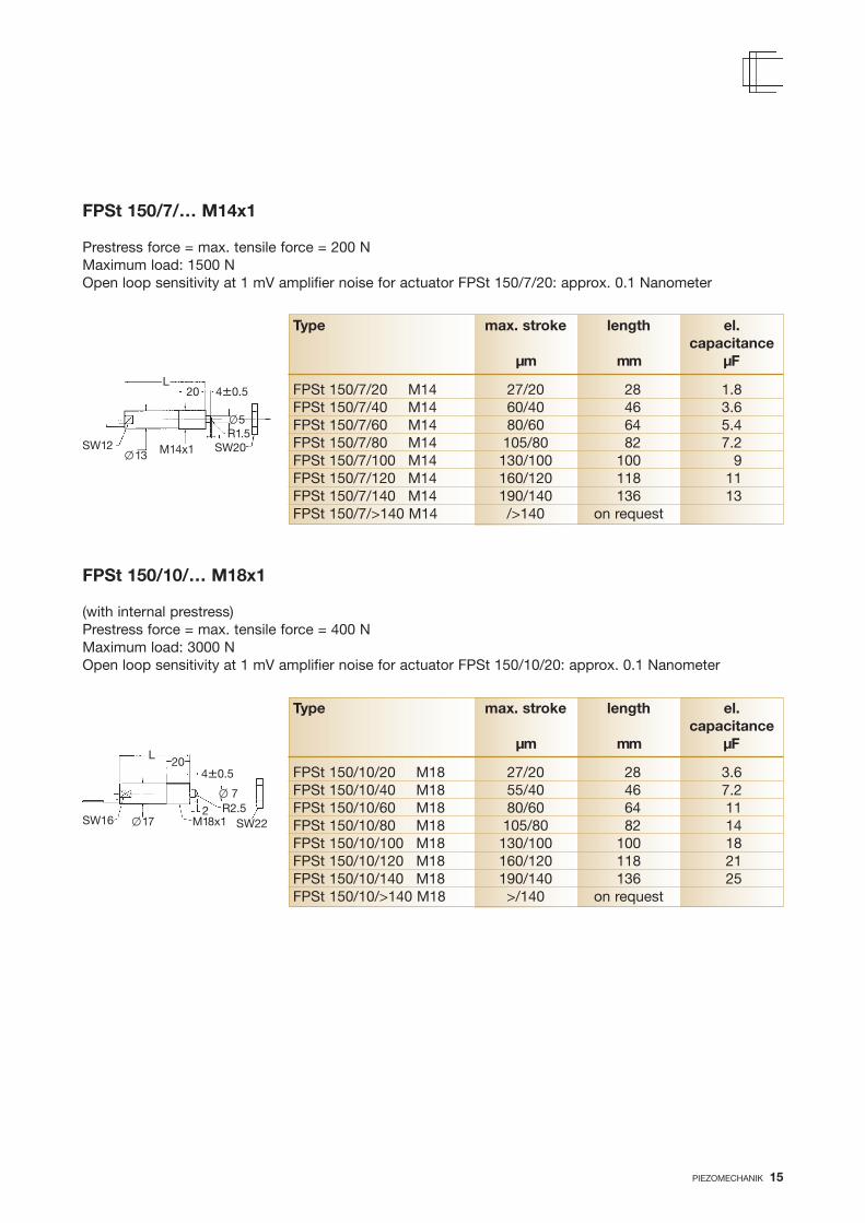
FPSt 150/7/… M14x1
Prestress force = max. tensile force = 200 NMaximum load: 1500 NOpen loop sensitivity at 1 mV amplifier noise for actuator FPSt 150/7/20: approx. 0.1 Nanometer
Type max. stroke length el.capacitance
µm mm µF
FPSt 150/7/20 M14 27/20 28 1.8FPSt 150/7/40 M14 60/40 46 3.6FPSt 150/7/60 M14 80/60 64 5.4FPSt 150/7/80 M14 105/80 82 7.2FPSt 150/7/100 M14 130/100 100 9FPSt 150/7/120 M14 160/120 118 11FPSt 150/7/140 M14 190/140 136 13FPSt 150/7/>140 M14 />140 on request
Type max. stroke length el.capacitance
µm mm µF
FPSt 150/10/20 M18 27/20 28 3.6FPSt 150/10/40 M18 55/40 46 7.2FPSt 150/10/60 M18 80/60 64 11FPSt 150/10/80 M18 105/80 82 14FPSt 150/10/100 M18 130/100 100 18FPSt 150/10/120 M18 160/120 118 21FPSt 150/10/140 M18 190/140 136 25FPSt 150/10/>140 M18 >/140 on request
FPSt 150/10/… M18x1
(with internal prestress)Prestress force = max. tensile force = 400 NMaximum load: 3000 NOpen loop sensitivity at 1 mV amplifier noise for actuator FPSt 150/10/20: approx. 0.1 Nanometer
20L
�13
R1.5SW20M14x1
�5
20L
�17R2.5
SW16 M18x12
4�0.5
SW12
4�0.5
� 7
SW22

1616 PIEZOMECHANIK
1.3 Low voltage electrostrictive stacks
ESt 150/5/… VS10
General data: see brochure: “First Steps towards Piezoaction”Prestress force = max. tensile force = 150 NMaximum compressive load: 500 NOpen loop sensitivity for ESt 150/5/6 VS10at 1 mV amplifier noise: approx. 0.05 Nanometer
VS 10
�10
SW 8 mmM3, 4 mm depth
M3, 4 mm depth
Operating voltage 0 V thru +150 V, arbitrary polarityBare stacks: on request
Stacks with preloaded casings VS
ESt 150/7/… VS12
General data: see brochure: “First Steps towards Piezoaction”Prestress force = max. tensile force = 200 NMaximum compressive load: 1000 NOpen loop sensitivity for ESt 150/7/6 VS12 at 1 mV amplifier noise: approx. 0.05 Nanometer
Type max. stroke length el. stiffnesscapacitance
µm mm nF N/µm
ESt 150/5/6 VS10 6 19 600 50ESt 150/5/12 VS10 12 28 1200 25ESt 150/5/18 VS10 18 37 1800 16ESt 150/5/25 VS10 25 46 2400 12
Type max. stroke length el. stiffnesscapacitance
µm mm µF N/µm
ESt 150/7/6 VS12 6 19 2 100ESt 150/7/12 VS12 12 28 4.2 50ESt 150/7/18 VS12 18 37 6.3 33ESt 150/7/25 VS12 25 46 8.4 25ESt 150/7/40 VS12 40 64 12.6 20
�4
4�0.5
�3
VS 12
�12
SW 10 mmM4, 4 mm depth
SW 4 mmM4, 4 mm depth
4�0.5
�3

17PIEZOMECHANIK 17
Electrostrictive stacks, frontmount cartridges versions
FESt 150/5/… M10x0.75 on request
FESt 150/5/… M12x0.5(-BD)
Maximum load: 500 NOpen loop sensitivity for 1 mV amplifier noisewith FESt 150/5/12 M12: approx. 0.1 Nanometer
Type max. stroke length el.capacitance
µm mm nF
FESt 150/5/12 M12 (BD) 12 31 1200FESt 150/5/18 M12 (BD) 18 40 1800FESt 150/5/25 M12 (BD) 25 48 2400FESt 150/5/40 M12 (BD) 40 67 3600
1.5 SW 12
L
6
M12
x0.5
FPSt
�14
15
1.5SW 12L
6
M12
x0.5
FPSt-BD
�14
26
8.5
�11

18 PIEZOMECHANIK
Options:
Threaded end pieces HAg(together with 1 screw cap)Optics adaptor 0A ½ ´´ (see section 3)
2. Ring Actuators (stack type hollow cylinders)
2.1 Low voltage ring actuators without casing
HPSt 150/14-10/xx
Type max. stroke length el. stiffness resonancecapacitance frequency
µm mm µF N/µm kHz
HPSt 150/14-10/12 16/12 13.5 2.6 250 75HPSt 150/14-10/25 32/25 27 5.2 120 22HPSt 150/14-10/40 50/40 on requestHPSt 150/14-10/55 70/55 on request
� 9
� 15
M 12x0.5
Polymer coating
L
Ceramic
�2Maximum force generation: 4500 NOpen loop sensitivity for 1 mV amplifier noise foractuator HPSt 150/14-10/12: approx. 0.1 Nanometer
Stroke A/B: A: for –30 V thru +150 VB: for 0 V thru +150 V
Max. force generation: for –30 V thru +150 V
�� 9
�� 15
� 8
� 7 � 5
� 6
� 9
HAg

PIEZOMECHANIK 19
Type max. stroke length el. stiffness resonancecapacitance frequency
µm mm µF N/µm kHz
HPSt 150/20-15/12 16/12 13.5 5 450 75HPSt 150/20-15/25 32/25 27 10 230 22HPSt 150/20-15/40 50/40 40.5 15 150 15HPSt 150/20-15/55 70/55 54 20 100 10
HPSt 150/20-15/xx
Maximum load: 11000 NMaximum force generation: 8000 NOpen loop sensitivity for 1 mV amplifier noise foractuator HPSt 150/20-15/12: approx. 0.1 Nanometer
�2
Polymer coating
L
Ceramic
Options:
Threaded end pieces HAg(together with 1 screw cap)Optics adaptor 0A 1 ´´ (see section 3)
Stroke A/B: A: for –30 V thru +150 VB: for 0 V thru +150 V
Max. force generation: for –30 V thru +150 V
� 25
� 15
M22x0.75
��14.5
�� 22
� 12 � 10
� 14
� 7 � 5

20 PIEZOMECHANIK
Type max. stroke length el. stiffness resonancecapacitance frequency
µm mm µF N/µm kHz
HPSt 150/14-10/12 VS22 16/12 31 2.6 250 30HPSt 150/14-10/25 VS22 32/25 44 5.2 120 20HPSt 150/14-10/40 VS22 50/40 58 7.8 70 14HPSt 150/14-10/55 VS22 70/50 71 11 50 9
HPSt 150/14-10/… VS22
Prestress force = max. tensile force = 400 NMaximum load: 6000 NMaximum force generation: 4500 NOpen loop sensitivity for 1 mV amplifier noise for actuator HPSt 150/14-10/12 VS22: approx. 0.1 Nanometer
M12x0.5
L
Standard configuration:
Coaxial cable RG 178 length 1 m with BNC connector
Options:
Coaxial cable RG 178 length 1 m with LEMO 00250 or 0S250 connectorUHV compatibilityLow temperature applicationThermostable modificationPosition sensorOptics adaptor 0A ½”: see section 3Adaptor rings AR: see section 3
Stroke A/B: A: for –30 V thru +150 VB: for 0 V thru +150 V
Max. force generation: for –30 V thru +150 V
� 5� 4
2.2 Low voltage ring actuators with internally prestressed casings
� 15� 9
� 8 � 6
� 9
� 4
� 22M12x0.5
M2, 4 mm depth
� 15
SW20
5.5�0.5
� 6

PIEZOMECHANIK 21
Type max. stroke length el. stiffness resonancecapacitance frequency
µm mm µF N/µm kHz
HPSt 150/20-15/12 VS35 16/12 31 5 450 30HPSt 150/20-15/25 VS35 32/25 44 10 230 20HPSt 150/20-15/40 VS35 50/40 58 15 150 17HPSt 150/20-15/55 VS35 70/50 71 20 100 15
HPSt 150/20-15/… VS35
General data: see brochure: “First Steps towards Piezoaction”Prestress force = max. tensile force = 700 NMaximum load: 11000 NMaximum force generation: 8000 NOpen loop sensitivity for 1 mV amplifier noise for actuator HPSt 150/20-15/12 VS35: approx. 0.1 Nanometer
L
Standard configuration:
Coaxial cable RG 178 length 1 m with BNC connector
Options:
Coaxial cable RG 178 length 1m with LEMO 00250 or 0S250 connectorUHV compatibilityLow temperature applicationThermostable modificationPosition detectorOptics adaptor 0A 1”: see section 3Adaptor rings AR: see section 3
Stroke A/B: A: for –30 V thru +150 VB: for 0 V thru +150 V
Max. force generation: for –30 V thru +150 V
� 4
� 25� 15
� 12 �10
� 14
� 5
� 35M22x0.75
4xM3, 5 mm depth
� 28
SW32
8�0.5
� 6
� M22x0.75
2222 PIEZOMECHANIK
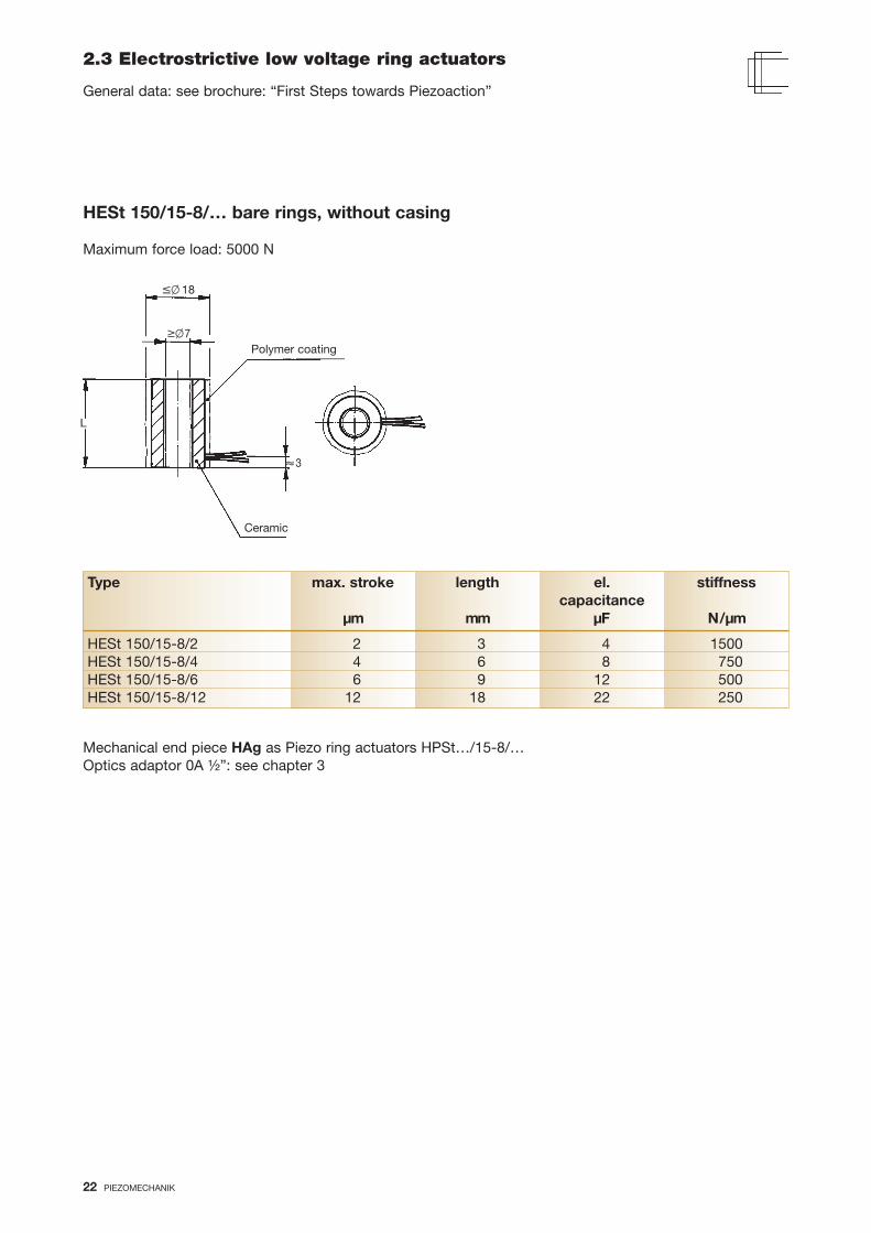
2.3 Electrostrictive low voltage ring actuators
General data: see brochure: “First Steps towards Piezoaction”
Mechanical end piece HAg as Piezo ring actuators HPSt…/15-8/…Optics adaptor 0A ½”: see chapter 3
HESt 150/15-8/… bare rings, without casing
Maximum force load: 5000 N
�3
Polymer coating
L
Ceramic
��7
�� 18
Type max. stroke length el. stiffnesscapacitance
µm mm µF N/µm
HESt 150/15-8/2 2 3 4 1500HESt 150/15-8/4 4 6 8 750HESt 150/15-8/6 6 9 12 500HESt 150/15-8/12 12 18 22 250

PIEZOMECHANIK 23PIEZOMECHANIK 23
HESt 150/15-8/… VS 22 casing with internal prestress
Prestress force = max. tensile force = 400 NMaximum load: 5000 NOpen loop sensitivity for 1 mV amplifier noise for actuatorHESt 150/15-8/6 VS22: 0.05 Nanometer
Type max. stroke length el. stiffnesscapacitance
µm mm µF N/µm
HESt 150/15-8/6 VS22 6 26 12 500HESt 150/15-8/12 VS22 12 35 22 250HEST 150/15-8/>12 VS22 on request
Standard configuration:
Coaxial cable RG 178 length 1 m with BNC connector
Options:
UHV compatibilityOptics adaptor 0A ½”: see section 3Adaptor rings AR: see section 3

24 PIEZOMECHANIK24 PIEZOMECHANIK
3. Accessories
thread3x120°
t
3.1 Electricals
Supply coaxial cables: one side connector, otherside free for attaching piezocomponents such asbare stacks etc.Cable type RG 178 (PTFE), thickness 1.8 mm:length 1.5 mConnectors available: BNC, LEMO 0S250Cable type RG 316 (PTFE), thickness 2.5 mm:length 1.5 mfor power applicationsConnectors available: BNC, LEMO 0S250
Designation AR X/Y X external diameter, Y internal diameter (corresponds to actuator’s casing’s diameter),T thickness of ring (all dimensions in mm)
0
D
3.2 Mechanics
Adaptor ringsThe adaptor rings are normally used to match the diameter of actuators with casing to mirror mounts, defi-ned for a distinct mirror’s diameter. An often used combination are ring actuators (e.g. with casing VS22),which are adopted to 2” mirror mount system. The proper adaptor ring is an AR (51/22).
AR 25/10 t 5AR 25/12 t 5AR 25/18 t 5AR 50/18 t 7AR 50/20 t 7AR 50/22 t 7AR 50/25 t 7AR 50/35 t 7
Extension cables:Connector system LEMO 0S250, length 2 m/4 m/6 mCable types RG 178 or RG 316 (see above)
Connecting adaptors for matching different connectingsystems plug (from electronics) /Cable’s connectorLEMO 0S 250/BNC (this adaptor is used to match amplifi ers with LEMO output to a component, having aBNC connector)BNC/LEMO 0S250BNC/LEMO 00250
d
AR 31/12 t 7AR 31/22 t 7AR 31/25 t 7AR 51/18 t 7AR 51/20 t 7AR 51/22 t 7AR 51/22 t 7AR 51/35 t 7

PIEZOMECHANIK 25PIEZOMECHANIK 25
3.4 Screw in front adaptor SE (For stacks with casings VS)
The adaptors have a threaded pin for simple attachment to the standard front pieces VS with tapped holeand provide a plane or spherical front to match the actuator for various uses. For example small mirrorscan be glued onto the plane faces.Designation: SE xx plane and SE x sphere, where xx represents the casing’s diameter, where it is mountedto (e.g. 12 for VS 12).
3.3 Optic adaptor for ring actuators
Ring actuators are often used within optical arrangements for precise adjustment of transmissive opticalcomponents e.g. within laser resonators or tunable etalons. The optic adaptors allow the simple mountingand changing of circular optics with the standard diameters 1/2” sand 1”.
Optic adaptor 0A ½”This element allows mounting of optics with diameter 1/2” up to a thickness of 8 mm. It can be simplyattached using the M12x0.5 thread to all the corresponding ring actuators with a HAg M12x0.5 end piece(bare rings) such as the HPSt 150/14-10/…, HPSt 500/15-8/…, HPSt 1000/15-8/… or the equivalent casedtypes with a VS22 casing.
Optic adaptor 0A 1”This element allows mounting of optics with diameter 1” up to a thickness of 8 mm. It can be simply atta-ched using the M22x0.5 thread to all the corresponding ring actuators with a HAg M22x0.75 end piece(bare rings) such as the HPSt 150/25-15/… or the equivalent cased types with a VS35 casing.
spehre
Magnetic front piecesBased on the above described front adaptors, MA components with magnetic plane face are offered for VS10 and VS12 casings (designationMA10 / MA12). Small ferromagnetic componentscan be easily attached to the moving pin of stack actuators.
Type Mx (mm) D (mm) L (mm) R (mm)
SE9 2.3 5 3 2.5SE10 3 6 3 2.5SE12 3 7 4 3.5SE15 4 8 4 3.5SE18/20 5 10 4 4
plane
M xxM xx
LL
22
R� D
0A ½’’ 0A 1’’
M14x0.5
M14x0.5
M12x0.5
� 2,5� 9
� 3�14 � 9 � 10
�16
M28x0.75
�16
� 2,5
M28x0.75
�17 � 25.5�11�12
� 4
M22x0.5
�30
�16

3.5 Piezo-stacks PSt 150/HPSt 150 (osi-type)
Dimensionsa, b, L refer to the ceramic structure,Tolerances: +/- 0.03 mm
Maximum voltage range(-)30 V/ (+)150 V
type ceramic- length L1) Max. Stroke 2) capacitance Resonance stiffness Blocking- Max. loadosi-stack crosssection frequency force3) force(+) Umax 150 V a x b /mm2 mm µm nF kHz N/µm N N
PSt 150/2x3/5 2 x 3 5 6.5/5 70 150 45 300 300
PSt 150/2x3/7 2 x 3 9 13/9 170 100 25 300 300
PSt 150/2x3/20 2 x 3 18 28/20 340 50 12 300 300
PSt 150/3.5x3.5/7 3.5 x 3.5 9 13/9 350 100 50 800 800
PSt 150/3.5x3.5/20 3.5 x 3.5 18 28/20 800 50 25 800 800
PSt 150/5x5/7 5 x 5 9 13/9 800 100 120 1600 2000
PSt 150/5x5/20 5 x 5 18 28/20 1800 50 60 1600 2000
PSt 150/7x7/7 7 x 7 9 13/9 1800 100 240 3500 4000
PSt 150/7x7/20 7 x 7 18 28/20 3600 50 120 3500 4000
PSt 150/10x10/7 10 x 10 9 13/9 3600 100 500 7000 8000
PSt 150/10x10/20 10 x 10 18 28/20 7200 50 250 7000 8000
PSt 150/14x14/20 14 x 14 18 28/20 14500 47 500 15000 16000
Ring-actuators Diameters(+) Umax 150 V a x b
HPSt 150/14-10/12 14 x 10 13.5 16/12 2600 75 250 4500 7000
HPSt 150/20-15/12 20 x 15 13.5 16/12 5000 75 450 8000 12000
1) direction of expansion2) activation (-)30 V 3) blocking force = max. force generation
defined for max. semi-bipolar operation
Actuator PSt with standard coating
a b
� 3
LL
� 3
Ø a
Ø b
26 PIEZOMECHANIK26 PIEZOMECHANIK

OptionsPosition sensing by strain gages
Spherical end-pieces(up to cross-sections 10 x 10 mm) (Fig. 23)
Low temperature operationCryo option 1: special coatingCryo option 2: electrical contact by kapton-
insulated Manganin wires forminimizing heat load
Actor with spherical end-pieces
Temperature range-273 °C thru approx. +120 °C (depends on coating,see below)(beyond 100 °C, PZT-performance degradesreversibly)
Coatingsstandard: high quality epoxy-based encapsulationtemperature range -50 °C thru +120 °Cvacuum/UHV grade thickness up to 0.5 mmSpecial coatings optional eg. for cryo applicationsthin coatings for stack packaging(thickness < 50 µm)
Extended to such actuators PSt. 150/axa/40 onrequest.
ab
� 3
L
r = a2
PIEZOMECHANIK 27PIEZOMECHANIK 27

Berg-am-Laim-Str. 64 · D-81673 Munich · Phone ++ 49 /89 /4614 67 96 · Fax ++ 49 /89 /4 316412e-mail: [email protected] · http://www.piezomechanik.com Sta
nd:
Mär
z 20
17
Piezomechanik · Dr. Lutz Pickelmann GmbH
Low voltage co-fired multilayerstacks, rings and chips for actuation(without casing)
Low voltage actuators with casings, high voltage actuators Check main catalogue
���������� ���������������������
������� ���
���������� ���������������������
������������
PositionFeedback control electronics
PosiCon.anfor piezoactuators(low voltage and high voltage actuators)
PiezomechanikGmbH
Above: PosiCon 150/3 with actuator PSt 150/14/20 VS 20, option: position detection.Sensor: white cable and actuator: brown cable are connected to channel I.
First Steps towards Piezoaction
Thermograph of a dynamically operated piezo stack
Piezomechanik_Product range_Low_2017:Piezomechanik_Mutilayer_Katalog 29.03.2017 18:02 Seite 28