PIEZOELECTRIC SOUND COMPONENTS - Arduino
39
Murata Manufacturing Co., Ltd. Cat.No.P37E-17 Piezoelectric Sound Components PIEZOELECTRIC SOUND COMPONENTS Please read CAUTION and Notice in this catalog for safety. This catalog has only typical specifications. Therefore you are requested to approve our product specification or to transact the approval sheet for product specification, before your ordering. P37E17.pdf 02.3.6
Transcript of PIEZOELECTRIC SOUND COMPONENTS - Arduino
MurataManufacturing Co., Ltd. Cat.No.P37E-17
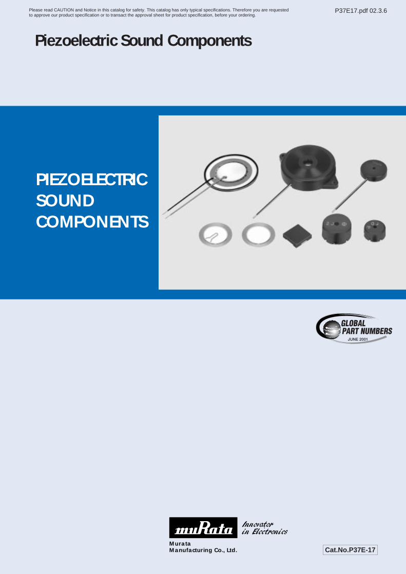
Piezoelectric Sound Components
PIEZOELECTRICSOUNDCOMPONENTS
Please read CAUTION and Notice in this catalog for safety. This catalog has only typical specifications. Therefore you are requestedto approve our product specification or to transact the approval sheet for product specification, before your ordering.
P37E17.pdf 02.3.6
1
2
3
4
5
6
7
8
9
10
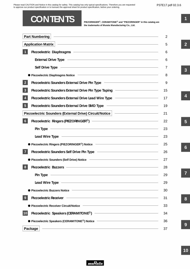
Part Numbering 2
Application Matrix 5
Piezoelectric Diaphragms 6
External Drive Type 6
Self Drive Type 7
Piezoelectric Diaphragms Notice 8
Piezoelectric Sounders External Drive Pin Type 9
Piezoelectric Sounders External Drive Pin Type Taping 15
Piezoelectric Sounders External Drive Lead Wire Type 17
Piezoelectric Sounders External Drive SMD Type 19
Piezoelectric Sounders (External Drive) Circuit/Notice 21
Piezoelectric Ringers (PIEZORINGERr) 22
Pin Type 23
Lead Wire Type 23
Piezoelectric Ringers (PIEZORINGERr) Notice 25
Piezoelectric Sounders Self Drive Pin Type 26
Piezoelectric Sounders (Self Drive) Notice 27
Piezoelectric Buzzers 28
Pin Type 29
Lead Wire Type 29
Piezoelectric Buzzers Notice 30
Piezoelectric Receiver 31
Piezoelectric Receiver Circuit/Notice 33
Piezoelectric Speakers (CERAMITONEr) 34
Piezoelectric Speakers (CERAMITONEr) Notice 36
Package 37
CONTENTS PIEZORINGERr, CERAMITONEr and "PIEZORINGER" in this catalog arethe trademarks of Murata Manufacturing Co., Ltd.
1
2
3
4
5
6
7
8
9
10
Please read CAUTION and Notice in this catalog for safety. This catalog has only typical specifications. Therefore you are requestedto approve our product specification or to transact the approval sheet for product specification, before your ordering.
P37E17.pdf 02.3.6
2
y
Y
e
13
w
M
r
E
t
P
u
-40
i
00
o
P
!0
-A0
q
PK
qProduct ID
wProduct
yStructure
iIndividual Specification Code
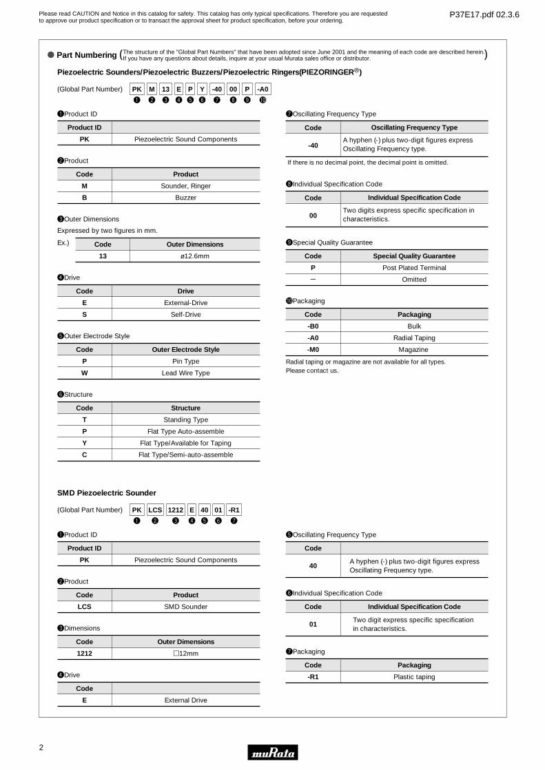
Piezoelectric Sounders/Piezoelectric Buzzers/Piezoelectric Ringers(PIEZORINGERr)
PK Piezoelectric Sound Components
T
P
Y
C
M
B
Sounder, Ringer
Buzzer
Standing Type
Flat Type Auto-assemble
Flat Type/Available for Taping
Flat Type/Semi-auto-assemble
Product
00
Individual Specification Code
Product ID
Code
Code
uOscillating Frequency Type
Structure
Code
(Global Part Number)
Pin Type
Lead Wire Type
eOuter Dimensions
rDrive
E
S
DriveCode
tOuter Electrode Style
P
W
Outer Electrode StyleCode
Post Plated Terminal
Omitted
oSpecial Quality Guarantee
P
Y
Special Quality GuaranteeCode
Bulk
Radial Taping
Magazine
!0Packaging
-B0
-A0
-M0
PackagingCode
Two digits express specific specification in characteristics.
Expressed by two figures in mm.
13
Ex.)
ø12.6mm
External-Drive
Self-Drive
Code Outer Dimensions
Radial taping or magazine are not available for all types.Please contact us.
-40
Oscillating Frequency TypeCode
A hyphen (-) plus two-digit figures express Oscillating Frequency type.
If there is no decimal point, the decimal point is omitted.
qProduct ID
SMD Piezoelectric Sounder
PK Piezoelectric Sound Components
Product ID
(Global Part Number)
y
01
e
1212
w
LCS
r
E
t
40
u
-R1
q
PK
wProduct
LCS SMD Sounder
Code Product
eDimensions
1212 p12mm
Code Outer Dimensions
rDrive
E External Drive
Code
tOscillating Frequency Type
40A hyphen (-) plus two-digit figures expressOscillating Frequency type.
Code
yIndividual Specification Code
01Two digit express specific specification in characteristics.
Code Individual Specification Code
uPackaging
-R1 Plastic taping
Code Packaging
o Part Numbering The structure of the "Global Part Numbers" that have been adopted since June 2001 and the meaning of each code are described herein.If you have any questions about details, inquire at your usual Murata sales office or distributor.( )
Please read CAUTION and Notice in this catalog for safety. This catalog has only typical specifications. Therefore you are requestedto approve our product specification or to transact the approval sheet for product specification, before your ordering.
P37E17.pdf 02.3.6
3
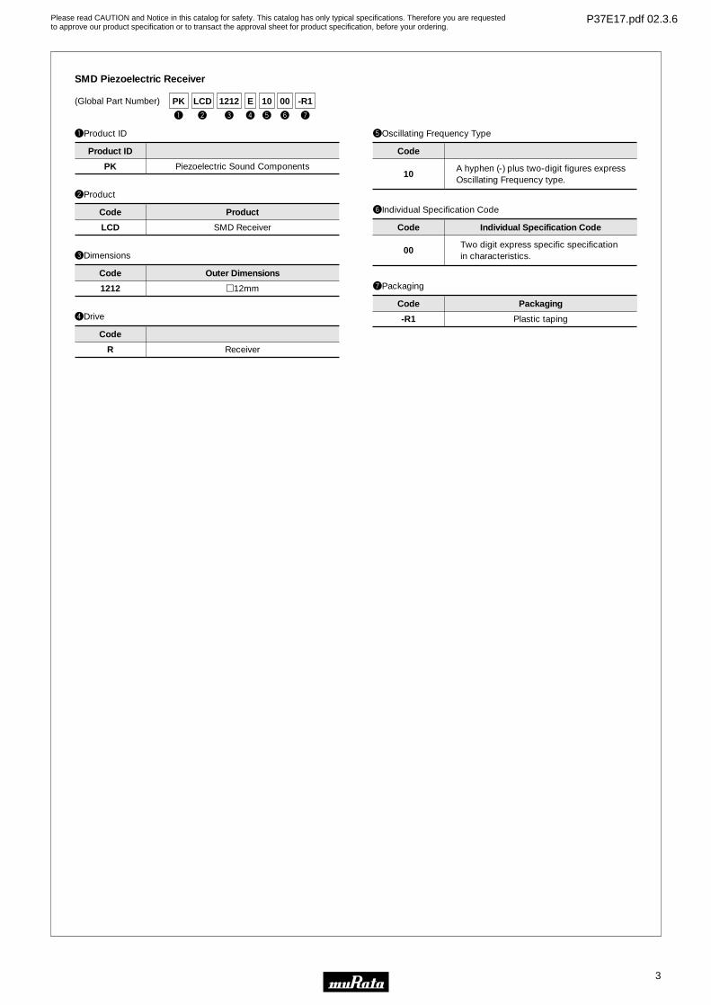
qProduct ID
SMD Piezoelectric Receiver
PK Piezoelectric Sound Components
Product ID
(Global Part Number)
y
00
e
1212
w
LCD
r
E
t
10
u
-R1
q
PK
wProduct
LCD SMD Receiver
Code Product
eDimensions
1212 p12mm
Code Outer Dimensions
rDrive
R Receiver
Code
tOscillating Frequency Type
10A hyphen (-) plus two-digit figures expressOscillating Frequency type.
Code
yIndividual Specification Code
00Two digit express specific specification in characteristics.
Code Individual Specification Code
uPackaging
-R1 Plastic taping
Code Packaging
Please read CAUTION and Notice in this catalog for safety. This catalog has only typical specifications. Therefore you are requestedto approve our product specification or to transact the approval sheet for product specification, before your ordering.
P37E17.pdf 02.3.6
4
y
-1R5
e
B
w
N
r
-31R2
t
DM
u i
A
o
10
q
7
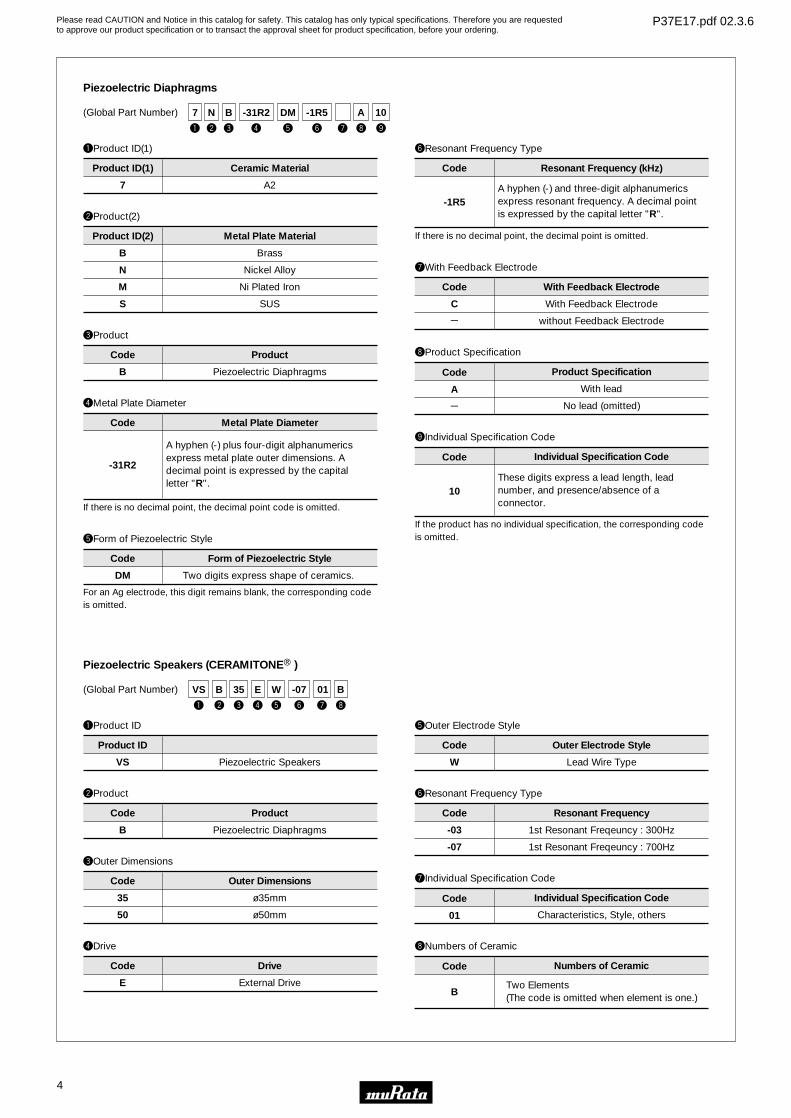
qProduct ID(1)
wProduct(2)
eProduct
uWith Feedback Electrode
oIndividual Specification Code
Piezoelectric Diaphragms
7 A2
C
e
B
N
M
S
Brass
Nickel Alloy
Ni Plated Iron
SUS
B Piezoelectric Diaphragms
Two digits express shape of ceramics.
With Feedback Electrode
without Feedback Electrode
With lead
No lead (omitted)
Product
10
Individual Specification Code
Product ID(1) Ceramic Material
Product ID(2) Metal Plate Material
Code
Code
iProduct Specification
A
e
Code
With Feedback Electrode
Product Specification
Code
(Global Part Number)
rMetal Plate Diameter
-31R2
Metal Plate DiameterCode
A hyphen (-) plus four-digit alphanumerics express metal plate outer dimensions. A decimal point is expressed by the capital letter "R".
tForm of Piezoelectric Style
DM
Form of Piezoelectric StyleCode
yResonant Frequency Type
-1R5
Resonant Frequency (kHz)Code
A hyphen (-) and three-digit alphanumerics express resonant frequency. A decimal point is expressed by the capital letter "R".
These digits express a lead length, lead number, and presence/absence of a connector. If there is no decimal point, the decimal point code is omitted.
For an Ag electrode, this digit remains blank, the corresponding code is omitted.
If there is no decimal point, the decimal point is omitted.
If the product has no individual specification, the corresponding code is omitted.
qProduct ID
wProduct
eOuter Dimensions
yResonant Frequency Type
iNumbers of Ceramic
Piezoelectric Speakers (CERAMITONEr )
VS Piezoelectric Speakers
-03
-07
B Piezoelectric Diaphragms
35
50
ø35mm
ø50mm
1st Resonant Freqeuncy : 300Hz
1st Resonant Freqeuncy : 700Hz
Characteristics, Style, others
Outer Dimensions
B
Numbers of Ceramic
Product ID
Code
Code
Code
uIndividual Specification Code
01
Code
Product Resonant Frequency
Individual Specification Code
Code
(Global Part Number)
Two Elements (The code is omitted when element is one.)
rDrive
E External Drive
DriveCode
tOuter Electrode Style
W Lead Wire Type
Outer Electrode StyleCode
y
-07
e
35
w
B
r
E
t
W
u
01
i
B
q
VS
Please read CAUTION and Notice in this catalog for safety. This catalog has only typical specifications. Therefore you are requestedto approve our product specification or to transact the approval sheet for product specification, before your ordering.
P37E17.pdf 02.3.6
5
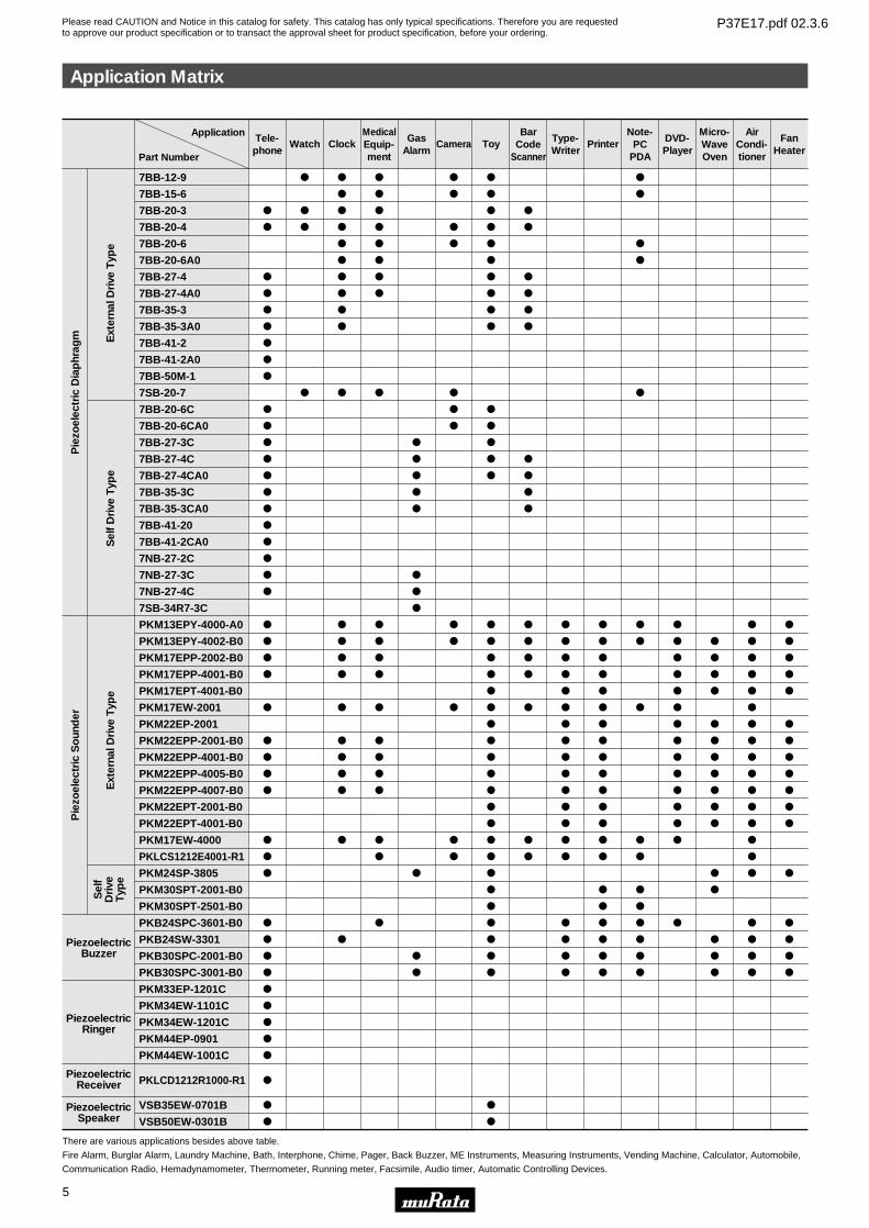
Application Matrix
Tele-phone
o
o
o
o
o
o
o
o
o
o
o
o
o
o
o
o
o
o
o
o
o
o
o
o
o
o
o
o
o
o
o
o
o
o
o
o
o
o
o
o
o
o
o
o
o
o
o
o
o
o
o
o
o
o
o
o
o
o
o
o
o
o
o
o
o
o
o
o
o
o
o
o
o
o
o
o
o
o
o
o
o
o
o
o
o
o
o
o
o
o
o
o
o
o
o
o
o
o
o
o
o
o
o
o
o
o
o
o
o
o
o
o
o
o
o
o
o
o
o
o
o
o
o
o
o
o
o
o
o
o
o
o
o
o
o
o
o
o
o
o
o
o
o
o
o
o
o
o
o
o
o
o
o
o
o
o
o
o
o
o
o
o
o
o
o
o
o
o
o
o
o
o
o
o
o
o
o
o
o
o
o
o
o
o
o
o
o
o
o
o
o
o
o
o
o
o
o
o
o
o
o
o
o
o
o
o
o
o
o
o
o
o
o
o
o
o
o
o
o
o
o
o
o
o
o
o
o
o
o
o
o
o
o
o
o
o
o
o
o
o
o
o
o
o
o
o
o
o
o
o
o
o
o
o
o
o
o
o
o
o
o
o
o
o
o
o
o
o
o
o
o
o
o
o
o
o
o
o
o
o
o
o
o
o
o
o
o
o
o
o
o
o
o
o
o
Watch ClockMedicalEquip-ment
GasAlarm
Camera ToyBar
CodeScanner
Type-Writer
PrinterNote-
PCPDA
DVD-Player
Micro-WaveOven
AirCondi-tioner
FanHeater
Ext
erna
l Dri
ve T
ype
Pie
zoel
ectr
ic D
iap
hrag
mP
iezo
elec
tric
So
und
er
Sel
f D
rive
Typ
eE
xter
nal D
rive
Typ
eS
elf
Dri
veT
ype
PiezoelectricBuzzer
PiezoelectricRinger
PiezoelectricSpeaker
PiezoelectricReceiver
7BB-12-9
7BB-15-6
7BB-20-3
7BB-20-4
7BB-20-6
7BB-20-6A0
7BB-27-4
7BB-27-4A0
7BB-35-3
7BB-35-3A0
7BB-41-2
7BB-41-2A0
7BB-50M-1
7SB-20-7
7BB-20-6C
7BB-20-6CA0
7BB-27-3C
7BB-27-4C
7BB-27-4CA0
7BB-35-3C
7BB-35-3CA0
7BB-41-20
7BB-41-2CA0
7NB-27-2C
7NB-27-3C
7NB-27-4C
7SB-34R7-3C
PKM13EPY-4000-A0
PKM13EPY-4002-B0
PKM17EPP-2002-B0
PKM17EPP-4001-B0
PKM17EPT-4001-B0
PKM17EW-2001
PKM22EP-2001
PKM22EPP-2001-B0
PKM22EPP-4001-B0
PKM22EPP-4005-B0
PKM22EPP-4007-B0
PKM22EPT-2001-B0
PKM22EPT-4001-B0
PKM17EW-4000
PKLCS1212E4001-R1
PKM24SP-3805
PKM30SPT-2001-B0
PKM30SPT-2501-B0
PKB24SPC-3601-B0
PKB24SW-3301
PKB30SPC-2001-B0
PKB30SPC-3001-B0
PKM33EP-1201C
PKM34EW-1101C
PKM34EW-1201C
PKM44EP-0901
PKM44EW-1001C
PKLCD1212R1000-R1
VSB35EW-0701B
VSB50EW-0301B
There are various applications besides above table.
Fire Alarm, Burglar Alarm, Laundry Machine, Bath, Interphone, Chime, Pager, Back Buzzer, ME Instruments, Measuring Instruments, Vending Machine, Calculator, Automobile,
Communication Radio, Hemadynamometer, Thermometer, Running meter, Facsimile, Audio timer, Automatic Controlling Devices.
Part Number
Application
Please read CAUTION and Notice in this catalog for safety. This catalog has only typical specifications. Therefore you are requestedto approve our product specification or to transact the approval sheet for product specification, before your ordering.
P37E17.pdf 02.3.6
Please read CAUTION and Notice in this catalog for safety. This catalog has only typical specifications. Therefore you are requestedto approve our product specification or to transact the approval sheet for product specification, before your ordering.
P37E17.pdf 02.3.6
6
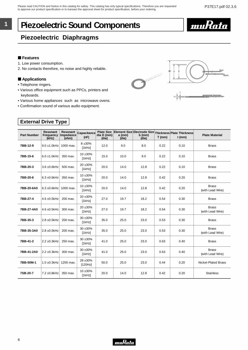
1 Piezoelectric Sound ComponentsPiezoelectric Diaphragms
Features1. Low power consumption.2. No contacts therefore, no noise and highly reliable.
Applications• Telephone ringers.• Various office equipment such as PPCs, printers and keyboards.• Various home appliances such as microwave ovens.• Confirmation sound of various audio equipment.
T
t
Red
Black
φD a b
External Drive Type
Part NumberResonantFrequency
(kHz)
ResonantImpedance
(ohm)
Capacitance(nF)
Plate Sizedia D (mm)
(dia)
Element Sizea (mm)
(dia)
Electrode Sizeb (mm)
(dia)
ThicknessT (mm)
Plate Thicknesst (mm)
Plate Material
7BB-12-9 9.0 ±1.0kHz 1000 max.8 ±30%[1kHz]
12.0 9.0 8.0 0.22 0.10 Brass
7BB-15-6 6.0 ±1.0kHz 350 max.10 ±30%
[1kHz]15.0 10.0 9.0 0.22 0.10 Brass
7BB-20-3 3.6 ±0.6kHz 500 max.20 ±30%
[1kHz]20.0 14.0 12.8 0.22 0.10 Brass
7BB-20-6 6.3 ±0.6kHz 350 max.10 ±30%
[1kHz]20.0 14.0 12.8 0.42 0.20 Brass
7BB-20-6A0 6.3 ±0.6kHz 1000 max.10 ±30%
[1kHz]20.0 14.0 12.8 0.42 0.20
Brass(with Lead Wire)
7BB-27-4 4.6 ±0.5kHz 200 max.20 ±30%
[1kHz]27.0 19.7 18.2 0.54 0.30 Brass
7BB-27-4A0 4.6 ±0.5kHz 300 max.20 ±30%
[1kHz]27.0 19.7 18.2 0.54 0.30
Brass(with Lead Wire)
7BB-35-3 2.8 ±0.5kHz 200 max.30 ±30%
[1kHz]35.0 25.0 23.0 0.53 0.30 Brass
7BB-35-3A0 2.8 ±0.5kHz 200 max.30 ±30%
[1kHz]35.0 25.0 23.0 0.53 0.30
Brass(with Lead Wire)
7BB-41-2 2.2 ±0.3kHz 250 max.30 ±30%
[1kHz]41.0 25.0 23.0 0.63 0.40 Brass
7BB-41-2A0 2.2 ±0.3kHz 300 max.30 ±30%
[1kHz]41.0 25.0 23.0 0.63 0.40
Brass(with Lead Wire)
7BB-50M-1 1.0 ±0.3kHz 1200 max.28 ±30%[120Hz]
50.0 25.0 23.0 0.44 0.20 Nickel-Plated Brass
7SB-20-7 7.2 ±0.8kHz 350 max.10 ±30%
[1kHz]20.0 14.0 12.8 0.42 0.20 Stainless
Please read CAUTION and Notice in this catalog for safety. This catalog has only typical specifications. Therefore you are requestedto approve our product specification or to transact the approval sheet for product specification, before your ordering.
P37E17.pdf 02.3.6
7
1
T
t
Red
BlackBlue
φD a b
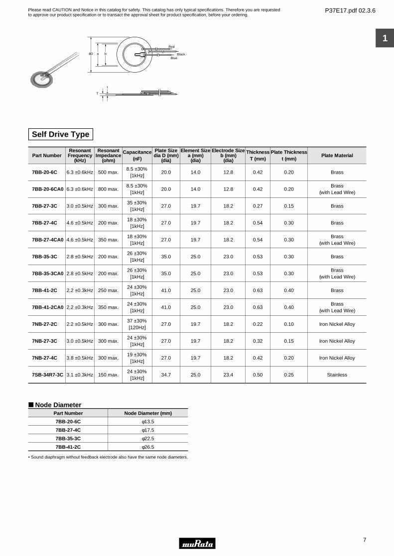
Self Drive Type
Part NumberResonantFrequency
(kHz)
ResonantImpedance
(ohm)
Capacitance(nF)
Plate Sizedia D (mm)
(dia)
Element Sizea (mm)
(dia)
Electrode Sizeb (mm)
(dia)
ThicknessT (mm)
Plate Thicknesst (mm)
Plate Material
7BB-20-6C 6.3 ±0.6kHz 500 max.8.5 ±30%
[1kHz]20.0 14.0 12.8 0.42 0.20 Brass
7BB-20-6CA0 6.3 ±0.6kHz 800 max.8.5 ±30%
[1kHz]20.0 14.0 12.8 0.42 0.20
Brass(with Lead Wire)
7BB-27-3C 3.0 ±0.5kHz 300 max.35 ±30%
[1kHz]27.0 19.7 18.2 0.27 0.15 Brass
7BB-27-4C 4.6 ±0.5kHz 200 max.18 ±30%
[1kHz]27.0 19.7 18.2 0.54 0.30 Brass
7BB-27-4CA0 4.6 ±0.5kHz 350 max.18 ±30%
[1kHz]27.0 19.7 18.2 0.54 0.30
Brass(with Lead Wire)
7BB-35-3C 2.8 ±0.5kHz 200 max.26 ±30%
[1kHz]35.0 25.0 23.0 0.53 0.30 Brass
7BB-35-3CA0 2.8 ±0.5kHz 200 max.26 ±30%
[1kHz]35.0 25.0 23.0 0.53 0.30
Brass(with Lead Wire)
7BB-41-2C 2.2 ±0.3kHz 250 max.24 ±30%
[1kHz]41.0 25.0 23.0 0.63 0.40 Brass
7BB-41-2CA0 2.2 ±0.3kHz 350 max.24 ±30%
[1kHz]41.0 25.0 23.0 0.63 0.40
Brass(with Lead Wire)
7NB-27-2C 2.2 ±0.5kHz 300 max.37 ±30%[120Hz]
27.0 19.7 18.2 0.22 0.10 Iron Nickel Alloy
7NB-27-3C 3.0 ±0.5kHz 300 max.24 ±30%
[1kHz]27.0 19.7 18.2 0.32 0.15 Iron Nickel Alloy
7NB-27-4C 3.8 ±0.5kHz 300 max.19 ±30%
[1kHz]27.0 19.7 18.2 0.42 0.20 Iron Nickel Alloy
7SB-34R7-3C 3.1 ±0.3kHz 150 max.24 ±30%
[1kHz]34.7 25.0 23.4 0.50 0.25 Stainless
Node Diameter
• Sound diaphragm without feedback electrode also have the same node diameters.
Part Number Node Diameter (mm)
7BB-20-6C
7BB-27-4C
7BB-35-3C
7BB-41-2C
φ13.5
φ17.5
φ22.5
φ26.5
Please read CAUTION and Notice in this catalog for safety. This catalog has only typical specifications. Therefore you are requestedto approve our product specification or to transact the approval sheet for product specification, before your ordering.
P37E17.pdf 02.3.6
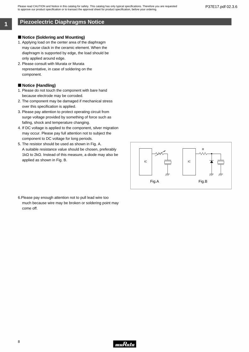
Piezoelectric Diaphragms Notice
8
1
Notice (Soldering and Mounting)1. Applying load on the center area of the diaphragm may cause clack in the ceramic element. When the diaphragm is supported by edge, the load should be only applied around edge.2. Please consult with Murata or Murata representative, in case of soldering on the component.
Notice (Handling)1. Please do not touch the component with bare hand
because electrode may be corroded.2. The component may be damaged if mechanical stress
over this specification is applied.3. Please pay attention to protect operating circuit from
surge voltage provided by something of force such as falling, shock and temperature changing.
4. If DC voltage is applied to the component, silver migration may occur. Please pay full attention not to subject the component to DC voltage for long periods.
5. The resistor should be used as shown in Fig. A. A suitable resistance value should be chosen, preferably
1kΩ to 2kΩ. Instead of this measure, a diode may also be applied as shown in Fig. B.
6.Please pay enough attention not to pull lead wire too much because wire may be broken or soldering point may come off.
IC
Fig.A
IC
Fig.B
R
Please read CAUTION and Notice in this catalog for safety. This catalog has only typical specifications. Therefore you are requestedto approve our product specification or to transact the approval sheet for product specification, before your ordering.
P37E17.pdf 02.3.6
9
2
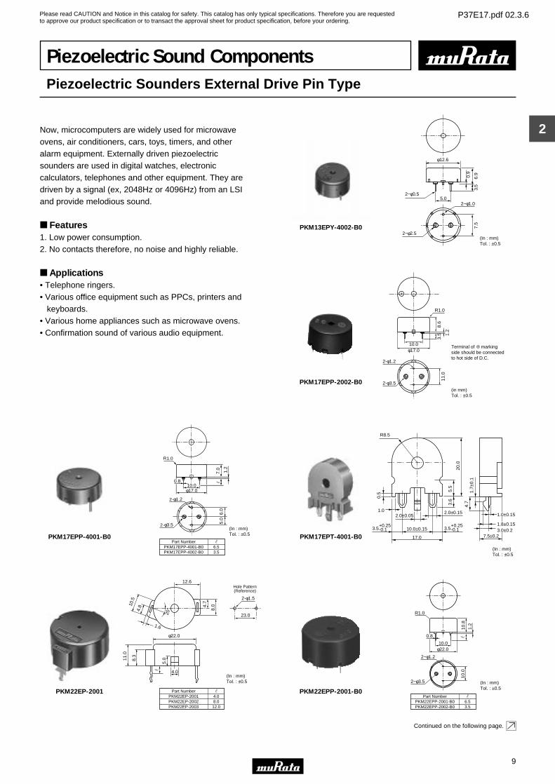
Piezoelectric Sound ComponentsPiezoelectric Sounders External Drive Pin Type
Now, microcomputers are widely used for microwave ovens, air conditioners, cars, toys, timers, and other alarm equipment. Externally driven piezoelectric sounders are used in digital watches, electronic calculators, telephones and other equipment. They are driven by a signal (ex, 2048Hz or 4096Hz) from an LSI and provide melodious sound.
Features1. Low power consumption.2. No contacts therefore, no noise and highly reliable.
Applications• Telephone ringers.• Various office equipment such as PPCs, printers and keyboards.• Various home appliances such as microwave ovens.• Confirmation sound of various audio equipment.
0.9
2−φ0.5
2−φ1.0
φ12.6
6.9
7.5
3.5
5.0
2−φ2.5(In : mm)Tol. : ±0.5
PKM13EPY-4002-B0
R1.0
2-φ1.2
2-φ3.5
8.6
11.0
3.5 1.
2
10.0φ17.0
Terminal of markingside should be connectedto hot side of D.C.
(in mm)Tol. : ±0.5
PKM17EPP-2002-B0
0.8
6.0
5.0
Part NumberPKM17EPP-4001-B0PKM17EPP-4002-B0
6.53.5
7.0
1.2
φ17.010.0
R1.0
2-φ1.2
2-φ3.5(In : mm)Tol. : ±0.5PKM17EPP-4001-B0
R8.5
17.0
1.0
10.0±0.15 3.5
20.0
0.5
2.0±0.15
+0.25-0.13.5
+0.25-0.1
5.5
3.6
4.7
1.7±
0.1
1.0±0.15
7.5±0.2
2.0±0.05
3.0±0.21.8±0.15
(In : mm)Tol. : ±0.5
PKM17EPT-4001-B0
12.6Hole Pattern(Reference)
23.0
2-φ1.5
20° 4.
7
8.0
φ22.0
4.0
5.08.
3
11.0
4.810
.5
1.6
Part NumberPKM22EP-2001PKM22EP-2002PKM22EP-2003
4.08.012.0
(In : mm)Tol. : ±0.5
PKM22EP-2001
10.8
1.2
φ22.010.0
R1.0
10.0
2−φ1.2
2−φ3.5 (In : mm)Tol. : ±0.5
Part NumberPKM22EPP-2001-B0PKM22EPP-2002-B0
6.53.5
0.8
PKM22EPP-2001-B0
Continued on the following page.
Please read CAUTION and Notice in this catalog for safety. This catalog has only typical specifications. Therefore you are requestedto approve our product specification or to transact the approval sheet for product specification, before your ordering.
P37E17.pdf 02.3.6
10
2
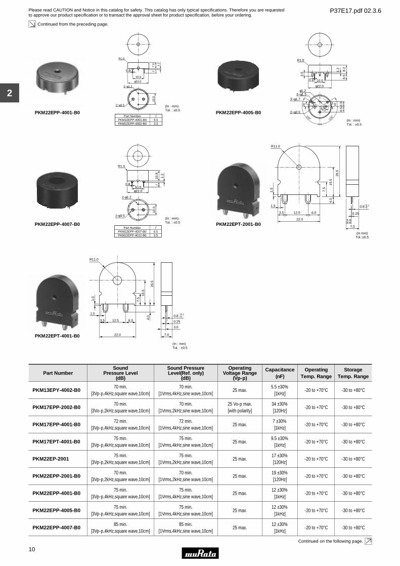
Continued from the preceding page.
7.0 1.2
φ22.0
10.0
R1.0
10.0
2−φ1.2
2−φ3.5 (In : mm)Tol. : ±0.5
Part NumberPKM22EPP-4001-B0PKM22EPP-4002-B0
6.53.5
0.8
PKM22EPP-4001-B0
3−φ1.5
10.0
18˚
18˚
120˚ 120˚
1.2
8.2
6.53.
5
R1.0
φ22.0
0.5
3−φ1.7
2−φ3.5
φ1.2
R8.5 0.5
(In : mm)Tol. : ±0.5
0.8
PKM22EPP-4005-B0
10.8
1.2
10.0
φ22.010.0
0.8
R1.0
2-φ1.2
2-φ3.5(In : mm)Tol. : ±0.5
Part NumberPKM22EPP-4007-B0PKM22EPP-4012-B0
6.53.5
PKM22EPP-4007-B0
1.0
7.5
15.5
4.0
26.5
0.8+0.1−0
R11.0
1.0
3.5 12.5
22.0
7.0
3.0
0.256.0
(in mm)Tol.:±0.5
PKM22EPT-2001-B0
R11.0
7.5
15.5
1.0
1.0
3.5 12.5
22.0
6.0
7.0
4.0
3.0
26.5
0.25
0.8 +0.1−0
(In : mm)Tol. : ±0.5
PKM22EPT-4001-B0
Part NumberSound
Pressure Level(dB)
Sound PressureLevel(Ref. only)
(dB)
OperatingVoltage Range
(Vp-p)
Capacitance(nF)
OperatingTemp. Range
StorageTemp. Range
PKM13EPY-4002-B070 min.
[3Vp-p,4kHz,square wave,10cm]70 min.
[1Vrms,4kHz,sine wave,10cm]25 max.
5.5 ±30%[1kHz]
-20 to +70°C -30 to +80°C
PKM17EPP-2002-B070 min.
[3Vo-p,2kHz,square wave,10cm]70 min.
[1Vrms,2kHz,sine wave,10cm]25 Vo-p max.[with polarity]
34 ±30%[120Hz]
-20 to +70°C -30 to +80°C
PKM17EPP-4001-B072 min.
[3Vp-p,4kHz,square wave,10cm]72 min.
[1Vrms,4kHz,sine wave,10cm]25 max.
7 ±30%[1kHz]
-20 to +70°C -30 to +80°C
PKM17EPT-4001-B075 min.
[3Vp-p,4kHz,square wave,10cm]75 min.
[1Vrms,4kHz,sine wave,10cm]25 max.
9.5 ±30%[1kHz]
-20 to +70°C -30 to +80°C
PKM22EP-200175 min.
[3Vp-p,2kHz,square wave,10cm]75 min.
[1Vrms,2kHz,sine wave,10cm]25 max.
17 ±30%[120Hz]
-20 to +70°C -30 to +80°C
PKM22EPP-2001-B070 min.
[3Vp-p,2kHz,square wave,10cm]70 min.
[1Vrms,2kHz,sine wave,10cm]25 max.
19 ±30%[120Hz]
-20 to +70°C -30 to +80°C
PKM22EPP-4001-B075 min.
[3Vp-p,4kHz,square wave,10cm]75 min.
[1Vrms,4kHz,sine wave,10cm]25 max.
12 ±30%[1kHz]
-20 to +70°C -30 to +80°C
PKM22EPP-4005-B075 min.
[3Vp-p,4kHz,square wave,10cm]75 min.
[1Vrms,4kHz,sine wave,10cm]25 max.
12 ±30%[1kHz]
-20 to +70°C -30 to +80°C
PKM22EPP-4007-B085 min.
[3Vp-p,4kHz,square wave,10cm]85 min.
[1Vrms,4kHz,sine wave,10cm]25 max.
12 ±30%[1kHz]
-20 to +70°C -30 to +80°C
Continued on the following page.
Please read CAUTION and Notice in this catalog for safety. This catalog has only typical specifications. Therefore you are requestedto approve our product specification or to transact the approval sheet for product specification, before your ordering.
P37E17.pdf 02.3.6
11
2
Part NumberSound
Pressure Level(dB)
Sound PressureLevel(Ref. only)
(dB)
OperatingVoltage Range
(Vp-p)
Capacitance(nF)
OperatingTemp. Range
StorageTemp. Range
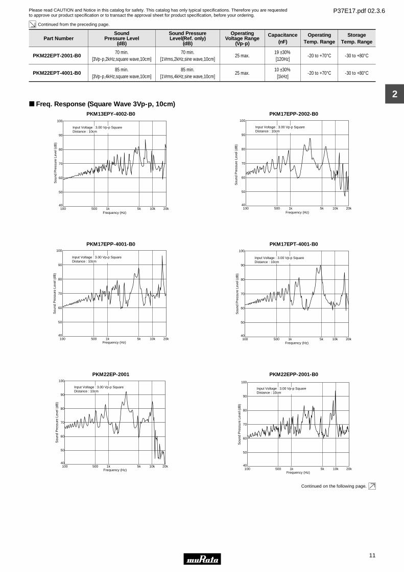
Continued from the preceding page.
PKM22EPT-2001-B070 min.
[3Vp-p,2kHz,square wave,10cm]70 min.
[1Vrms,2kHz,sine wave,10cm]25 max.
19 ±30%[120Hz]
-20 to +70°C -30 to +80°C
PKM22EPT-4001-B085 min.
[3Vp-p,4kHz,square wave,10cm]85 min.
[1Vrms,4kHz,sine wave,10cm]25 max.
10 ±30%[1kHz]
-20 to +70°C -30 to +80°C
Freq. Response (Square Wave 3Vp-p, 10cm)PKM13EPY-4002-B0
Sou
nd P
ress
ure
Leve
l (dB
)
40
50
Frequency (Hz)100 500 1k 5k 10k 20k
60
70
80
90
100
Input Voltage : 3.00 Vp-p SquareDistance : 10cm
PKM17EPP-2002-B0
Sou
nd P
ress
ure
Leve
l (dB
)
40
50
Frequency (Hz)100 500 1k 5k 10k 20k
60
70
80
90
100
Input Voltage : 3.00 Vp-p SquareDistance : 10cm
PKM17EPP-4001-B0
Sou
nd P
ress
ure
Leve
l (dB
)
40
50
Frequency (Hz)100 500 1k 5k 10k 20k
60
70
80
90
100
Input Voltage : 3.00 Vp-p SquareDistance : 10cm
PKM17EPT-4001-B0S
ound
Pre
ssur
e Le
vel (
dB)
40
50
Frequency (Hz)100 500 1k 5k 10k 20k
60
70
80
90
100
Input Voltage : 3.00 Vp-p SquareDistance : 10cm
PKM22EP-2001
Sou
nd P
ress
ure
Leve
l (dB
)
40
50
Frequency (Hz)100 500 1k 5k 10k 20k
60
70
80
90
100
Input Voltage : 3.00 Vp-p SquareDistance : 10cm
PKM22EPP-2001-B0
Sou
nd P
ress
ure
Leve
l (dB
)
40
50
Frequency (Hz)100 500 1k 5k 10k 20k
60
70
80
90
100
Input Voltage : 3.00 Vp-p SquareDistance : 10cm
Continued on the following page.
Please read CAUTION and Notice in this catalog for safety. This catalog has only typical specifications. Therefore you are requestedto approve our product specification or to transact the approval sheet for product specification, before your ordering.
P37E17.pdf 02.3.6
12
2
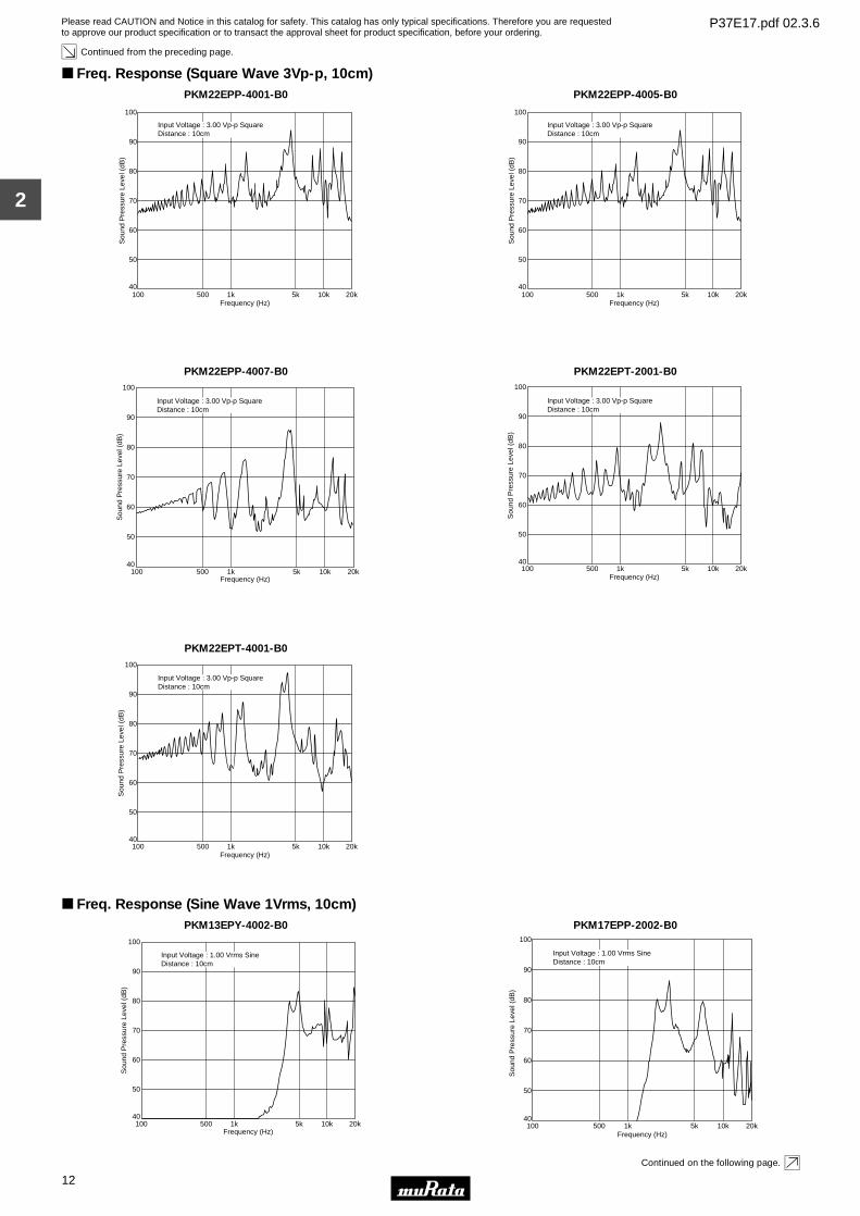
Continued from the preceding page.
Freq. Response (Square Wave 3Vp-p, 10cm)PKM22EPP-4001-B0
Sou
nd P
ress
ure
Leve
l (dB
)
40
50
Frequency (Hz)100 500 1k 5k 10k 20k
60
70
80
90
100
Input Voltage : 3.00 Vp-p SquareDistance : 10cm
PKM22EPP-4005-B0
Sou
nd P
ress
ure
Leve
l (dB
)
40
50
Frequency (Hz)100 500 1k 5k 10k 20k
60
70
80
90
100
Input Voltage : 3.00 Vp-p SquareDistance : 10cm
PKM22EPP-4007-B0
Sou
nd P
ress
ure
Leve
l (dB
)
40
50
Frequency (Hz)100 500 1k 5k 10k 20k
60
70
80
90
100
Input Voltage : 3.00 Vp-p SquareDistance : 10cm
PKM22EPT-2001-B0
Sou
nd P
ress
ure
Leve
l (dB
)
40
50
Frequency (Hz)100 500 1k 5k 10k 20k
60
70
80
90
100
Input Voltage : 3.00 Vp-p SquareDistance : 10cm
PKM22EPT-4001-B0
Sou
nd P
ress
ure
Leve
l (dB
)
40
50
Frequency (Hz)100 500 1k 5k 10k 20k
60
70
80
90
100
Input Voltage : 3.00 Vp-p SquareDistance : 10cm
Freq. Response (Sine Wave 1Vrms, 10cm)PKM13EPY-4002-B0
Sou
nd P
ress
ure
Leve
l (dB
)
40
50
Frequency (Hz)100 500 1k 5k 10k 20k
60
70
80
90
100
Input Voltage : 1.00 Vrms SineDistance : 10cm
PKM17EPP-2002-B0
Sou
nd P
ress
ure
Leve
l (dB
)
40
50
Frequency (Hz)100 500 1k 5k 10k 20k
60
70
80
90
100
Input Voltage : 1.00 Vrms SineDistance : 10cm
Continued on the following page.
Please read CAUTION and Notice in this catalog for safety. This catalog has only typical specifications. Therefore you are requestedto approve our product specification or to transact the approval sheet for product specification, before your ordering.
P37E17.pdf 02.3.6
13
2
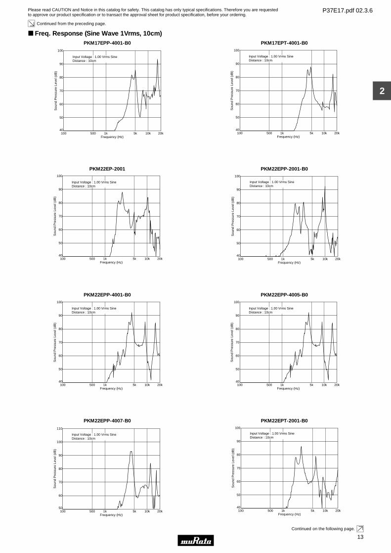
Continued from the preceding page.
Freq. Response (Sine Wave 1Vrms, 10cm)PKM17EPP-4001-B0
Sou
nd P
ress
ure
Leve
l (dB
)
40
50
Frequency (Hz)100 500 1k 5k 10k 20k
60
70
80
90
100
Input Voltage : 1.00 Vrms SineDistance : 10cm
PKM17EPT-4001-B0
Sou
nd P
ress
ure
Leve
l (dB
)
40
50
Frequency (Hz)100 500 1k 5k 10k 20k
60
70
80
90
100
Input Voltage : 1.00 Vrms SineDistance : 10cm
PKM22EP-2001
Sou
nd P
ress
ure
Leve
l (dB
)
40
50
Frequency (Hz)100 500 1k 5k 10k 20k
60
70
80
90
100
Input Voltage : 1.00 Vrms SineDistance : 10cm
PKM22EPP-2001-B0
Sou
nd P
ress
ure
Leve
l (dB
)
40
50
Frequency (Hz)100 500 1k 5k 10k 20k
60
70
80
90
100
Input Voltage : 1.00 Vrms SineDistance : 10cm
PKM22EPP-4001-B0
Sou
nd P
ress
ure
Leve
l (dB
)
40
50
Frequency (Hz)100 500 1k 5k 10k 20k
60
70
80
90
100
Input Voltage : 1.00 Vrms SineDistance : 10cm
PKM22EPP-4005-B0
Sou
nd P
ress
ure
Leve
l (dB
)
40
50
Frequency (Hz)100 500 1k 5k 10k 20k
60
70
80
90
100
Input Voltage : 1.00 Vrms SineDistance : 10cm
PKM22EPP-4007-B0
Sou
nd P
ress
ure
Leve
l (dB
)
50
60
Frequency (Hz)100 500 1k 5k 10k 20k
70
80
90
100
110
Input Voltage : 1.00 Vrms SineDistance : 10cm
PKM22EPT-2001-B0
Sou
nd P
ress
ure
Leve
l (dB
)
40
50
Frequency (Hz)100 500 1k 5k 10k 20k
60
70
80
90
100
Input Voltage : 1.00 Vrms SineDistance : 10cm
Continued on the following page.
Please read CAUTION and Notice in this catalog for safety. This catalog has only typical specifications. Therefore you are requestedto approve our product specification or to transact the approval sheet for product specification, before your ordering.
P37E17.pdf 02.3.6
14
2
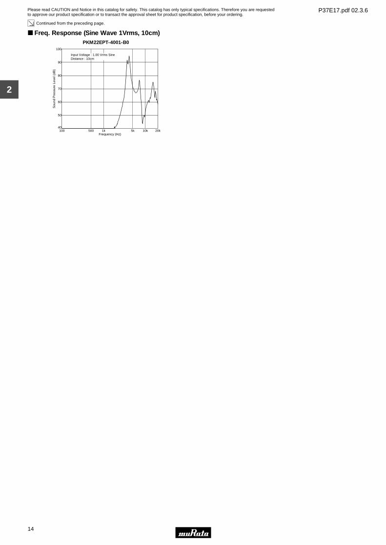
Continued from the preceding page.
Freq. Response (Sine Wave 1Vrms, 10cm)PKM22EPT-4001-B0
Sou
nd P
ress
ure
Leve
l (dB
)
40
50
Frequency (Hz)100 500 1k 5k 10k 20k
60
70
80
90
100
Input Voltage : 1.00 Vrms SineDistance : 10cm
Please read CAUTION and Notice in this catalog for safety. This catalog has only typical specifications. Therefore you are requestedto approve our product specification or to transact the approval sheet for product specification, before your ordering.
P37E17.pdf 02.3.6
15
3
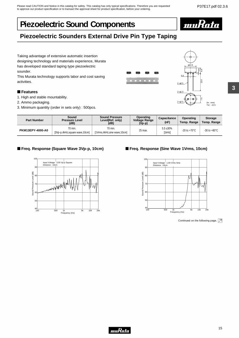
Piezoelectric Sound ComponentsPiezoelectric Sounders External Drive Pin Type Taping
Taking advantage of extensive automatic insertiondesigning technology and materials experience, Murata has developed standard taping type piezoelectric sounder.This Murata technology supports labor and cost saving activities.
Features1. High and stable mountability.2. Ammo packaging.3. Minimum quantity (order in sets only) : 500pcs.
0.9
2−φ0.5
2−φ1.0
φ12.6
6.9
7.5
22.0
5.0
2−φ2.5 (In : mm)Tol. : ±0.5
Part NumberSound
Pressure Level(dB)
Sound PressureLevel(Ref. only)
(dB)
OperatingVoltage Range
(Vp-p)
Capacitance(nF)
OperatingTemp. Range
StorageTemp. Range
PKM13EPY-4000-A070 min.
[3Vp-p,4kHz,square wave,10cm]70 min.
[1Vrms,4kHz,sine wave,10cm]25 max.
5.5 ±30%[1kHz]
-20 to +70°C -30 to +80°C
Freq. Response (Square Wave 3Vp-p, 10cm)
Sou
nd P
ress
ure
Leve
l (dB
)
40
50
Frequency (Hz)100 500 1k 5k 10k 20k
60
70
80
90
100
Input Voltage : 3.00 Vp-p SquareDistance : 10cm
Freq. Response (Sine Wave 1Vrms, 10cm)
Sou
nd P
ress
ure
Leve
l (dB
)
40
50
Frequency (Hz)100 500 1k 5k 10k 20k
60
70
80
90
100
Input Voltage : 1.00 Vrms SineDistance : 10cm
Continued on the following page.
Please read CAUTION and Notice in this catalog for safety. This catalog has only typical specifications. Therefore you are requestedto approve our product specification or to transact the approval sheet for product specification, before your ordering.
P37E17.pdf 02.3.6
16
3
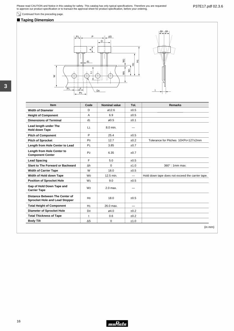
Continued from the preceding page.
Taping Dimension
Item
Width of Diameter
Height of Component
Dimensions of Terminal
Lead length under TheHold down Tape
Pitch of Component
Pitch of Sprocket
Length from Hole Center to Lead
Length from Hole Center toComponent Center
Lead Spacing
Slant to The Forward or Backward
Width of Carrier Tape
Width of Hold down Tape
Position of Sprocket Hole
Gap of Hold Down Tape andCarrier Tape
Distance Between The Center ofSprocket Hole and Lead Stopper
Total Height of Component
Diameter of Sprocket Hole
Total Thickness of Tape
Body Tilt
D
A
d1
L1
P
P0
P1
P2
F
∆h
W
W0
W1
W2
H0
H1
D0
t
∆S
(in mm)
Code
±0.5
±0.5
±0.1
—
±0.5
±0.2
±0.7
±0.7
±0.5
±1.0
±0.5
—
±0.5
—
±0.5
—
±0.2
±0.2
±1.0
Tol.
Tolerance for Pitches 10ZP0=127±2mm
360° : 1mm max.
Hold down tape does not exceed the carrier tape.
Remarks
ø12.6
6.9
ø0.5
8.0 min.
25.4
12.7
3.85
6.35
5.0
0
18.0
12.5 min.
9.0
2.0 max.
18.0
26.0 max.
ø4.0
0.6
0
Nominal value
H1
H0
W1
PP2
∆h ∆h
tP0
D0P1 F
d1
∆S
AL1
D
W0
W
W2
Please read CAUTION and Notice in this catalog for safety. This catalog has only typical specifications. Therefore you are requestedto approve our product specification or to transact the approval sheet for product specification, before your ordering.
P37E17.pdf 02.3.6
17
4
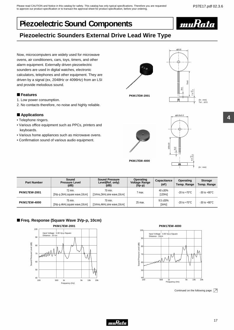
Piezoelectric Sound ComponentsPiezoelectric Sounders External Drive Lead Wire Type
Now, microcomputers are widely used for microwave ovens, air conditioners, cars, toys, timers, and other alarm equipment. Externally driven piezoelectric sounders are used in digital watches, electronic calculators, telephones and other equipment. They are driven by a signal (ex, 2048Hz or 4096Hz) from an LSI and provide melodious sound.
Features1. Low power consumption.2. No contacts therefore, no noise and highly reliable.
Applications• Telephone ringers.• Various office equipment such as PPCs, printers and keyboards.• Various home appliances such as microwave ovens.• Confirmation sound of various audio equipment.
70±5
3±1
φ16.8
(In : mm)Tol. : ±0.5
7.0
+0
–0.3
PKM17EW-2001
φ16.8±0.2
100±
10
4.0
+0
–0.3
(In : mm)
5±2
PKM17EW-4000
Part NumberSound
Pressure Level(dB)
Sound PressureLevel(Ref. only)
(dB)
OperatingVoltage Range
(Vp-p)
Capacitance(nF)
OperatingTemp. Range
StorageTemp. Range
PKM17EW-200172 min.
[3Vp-p,2kHz,square wave,10cm]70 min.
[1Vrms,2kHz,sine wave,10cm]7 max.
40 ±30%[120Hz]
-20 to +70°C -30 to +80°C
PKM17EW-400075 min.
[3Vp-p,4kHz,square wave,10cm]70 min.
[1Vrms,4kHz,sine wave,10cm]25 max.
9.5 ±30%[1kHz]
-20 to +70°C -30 to +80°C
Freq. Response (Square Wave 3Vp-p, 10cm)PKM17EW-2001
100 500 1k 5k 10k 20k
50
40
60
70
80
90
100
Frequency (Hz)
Sou
nd P
ress
ure
Leve
l (dB
)
Input Voltage : 3.00 Vp-p SquareDistance : 10 cm
PKM17EW-4000
Sou
nd P
ress
ure
Leve
l (dB
)
40
50
Frequency (Hz)100 500 1k 5k 10k 20k
60
70
80
90
100
Input Voltage : 3.00 Vp-p SquareDistance : 10cm
Continued on the following page.
Please read CAUTION and Notice in this catalog for safety. This catalog has only typical specifications. Therefore you are requestedto approve our product specification or to transact the approval sheet for product specification, before your ordering.
P37E17.pdf 02.3.6
18
4
Continued from the preceding page.
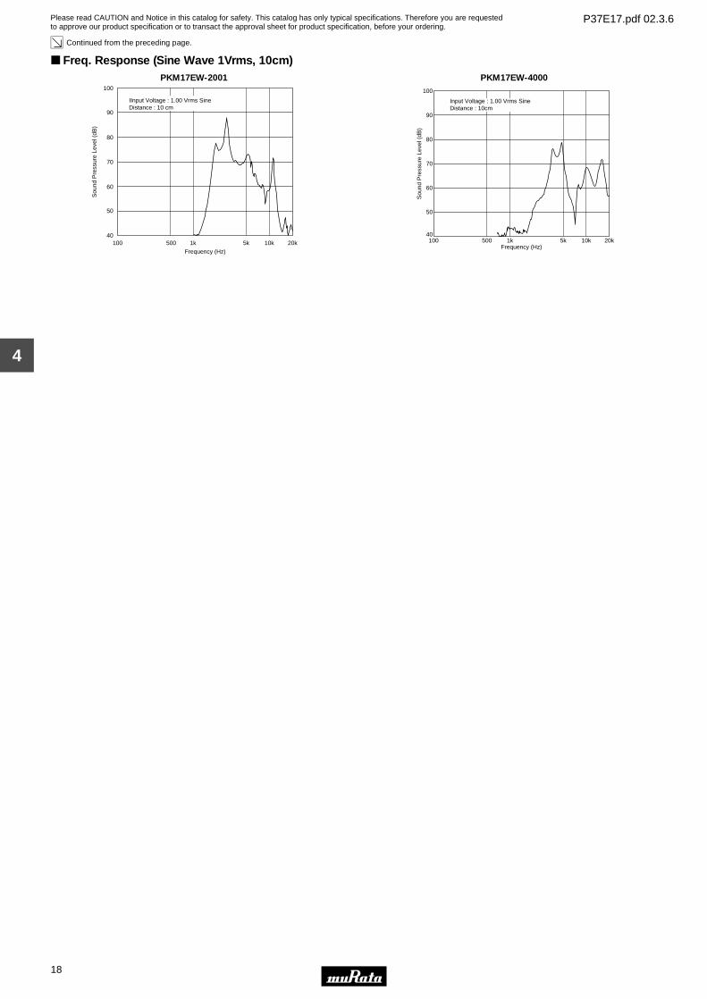
Freq. Response (Sine Wave 1Vrms, 10cm)PKM17EW-2001
100 500 1k 5k 10k 20k
50
40
60
70
80
90
100
Frequency (Hz)
Sou
nd P
ress
ure
Leve
l (dB
) IInput Voltage : 1.00 Vrms SineDistance : 10 cm
PKM17EW-4000
Sou
nd P
ress
ure
Leve
l (dB
)
40
50
Frequency (Hz)100 500 1k 5k 10k 20k
60
70
80
90
100
Input Voltage : 1.00 Vrms SineDistance : 10cm
Please read CAUTION and Notice in this catalog for safety. This catalog has only typical specifications. Therefore you are requestedto approve our product specification or to transact the approval sheet for product specification, before your ordering.
P37E17.pdf 02.3.6
19
5
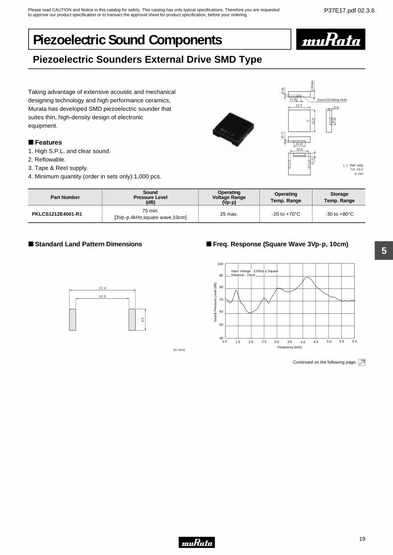
Piezoelectric Sound ComponentsPiezoelectric Sounders External Drive SMD Type
Taking advantage of extensive acoustic and mechanicaldesigning technology and high performance ceramics, Murata has developed SMD piezoelectric sounder thatsuites thin, high-density design of electronic equipment.
Features1. High S.P.L. and clear sound.2. Reflowable.3. Tape & Reel supply.4. Minimum quantity (order in sets only):1,000 pcs.
3.0m
ax.
0.9
4.0
(0.7
)
(6.4)
10.0
(2.1
)
12.0
12.0
(1.9)
(0.9
)
Sound Emitting Hole
in mm
( ) : Ref. onlyTol. ±0.2
Part NumberSound
Pressure Level(dB)
OperatingVoltage Range
(Vp-p)
OperatingTemp. Range
StorageTemp. Range
PKLCS1212E4001-R175 min.
[3Vp-p,4kHz,square wave,10cm]25 max. -20 to +70°C -30 to +80°C
Standard Land Pattern Dimensions
10.0
12.4
4.0
(in mm)
Freq. Response (Square Wave 3Vp-p, 10cm)
Ferquency (kHz)
100
90
80
70
60
50
401.0 1.5 2.0 2.5 3.0 3.5 4.0 4.5 5.0 5.5 6.0
Sou
nd P
ress
ure
Leve
l (dB
)
Input Voltage : 3.00Vp-p SquareDistance : 10cm
Continued on the following page.
Please read CAUTION and Notice in this catalog for safety. This catalog has only typical specifications. Therefore you are requestedto approve our product specification or to transact the approval sheet for product specification, before your ordering.
P37E17.pdf 02.3.6
20
5
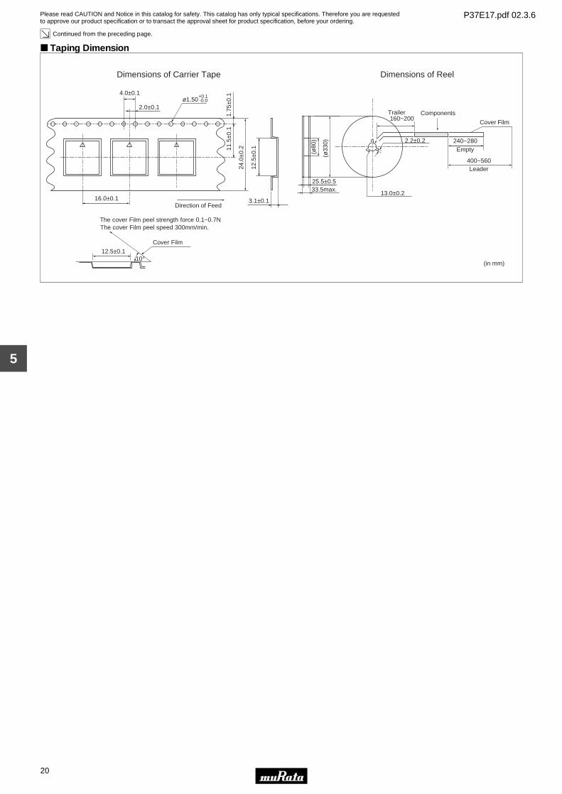
Continued from the preceding page.
Taping Dimension
Dimensions of Carrier Tape Dimensions of Reel
(in mm)
+0.1
24.0
±0.211
.5±0
.11.
75±0
.1
ø1.502.0±0.1
4.0±0.1
16.0±0.1
12.5
±0.1
3.1±0.1Direction of Feed
-0.0
12.5±0.1
Cover Film
The cover Film peel strength force 0.1~0.7NThe cover Film peel speed 300mm/min.
10°
13.0±0.233.5max.
(ø33
0)
160~200
240~2802.2±0.2
ComponentsTrailer
Empty
Leader
(ø80
)
400~560
25.5±0.5
Cover Film
Please read CAUTION and Notice in this catalog for safety. This catalog has only typical specifications. Therefore you are requestedto approve our product specification or to transact the approval sheet for product specification, before your ordering.
P37E17.pdf 02.3.6
Piezoelectric Sounders (External Drive) Circuit/Notice
21
5
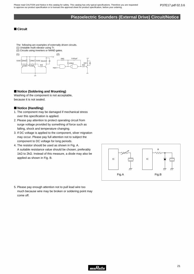
Circuit
510Ω 20kΩ 20kΩ 510Ω 55mH
+V
1kΩ0.01µF0.01µF
+V
1kΩ1kΩ120kΩ
1MΩ
Input
0.001µF
The following are examples of externally driven circuits.(1) Unstable multi-vibrator using Tr.(2) Circuits using inverters or NAND gates.
(1) (2)
Notice (Soldering and Mounting)Washing of the component is not acceptable, because it is not sealed.
Notice (Handling)1. The component may be damaged if mechanical stress
over this specification is applied.2. Please pay attention to protect operating circuit from
surge voltage provided by something of force such as falling, shock and temperature changing.
3. If DC voltage is applied to the component, silver migration may occur. Please pay full attention not to subject the component to DC voltage for long periods.
4. The resistor should be used as shown in Fig. A. A suitable resistance value should be chosen, preferably
1kΩ to 2kΩ. Instead of this measure, a diode may also be applied as shown in Fig. B.
5. Please pay enough attention not to pull lead wire too much because wire may be broken or soldering point may come off.
IC
Fig.A
IC
Fig.B
R
Please read CAUTION and Notice in this catalog for safety. This catalog has only typical specifications. Therefore you are requestedto approve our product specification or to transact the approval sheet for product specification, before your ordering.
P37E17.pdf 02.3.6
22
6
Piezoelectric Sound ComponentsPiezoelectric Ringers (PIEZORINGERr)
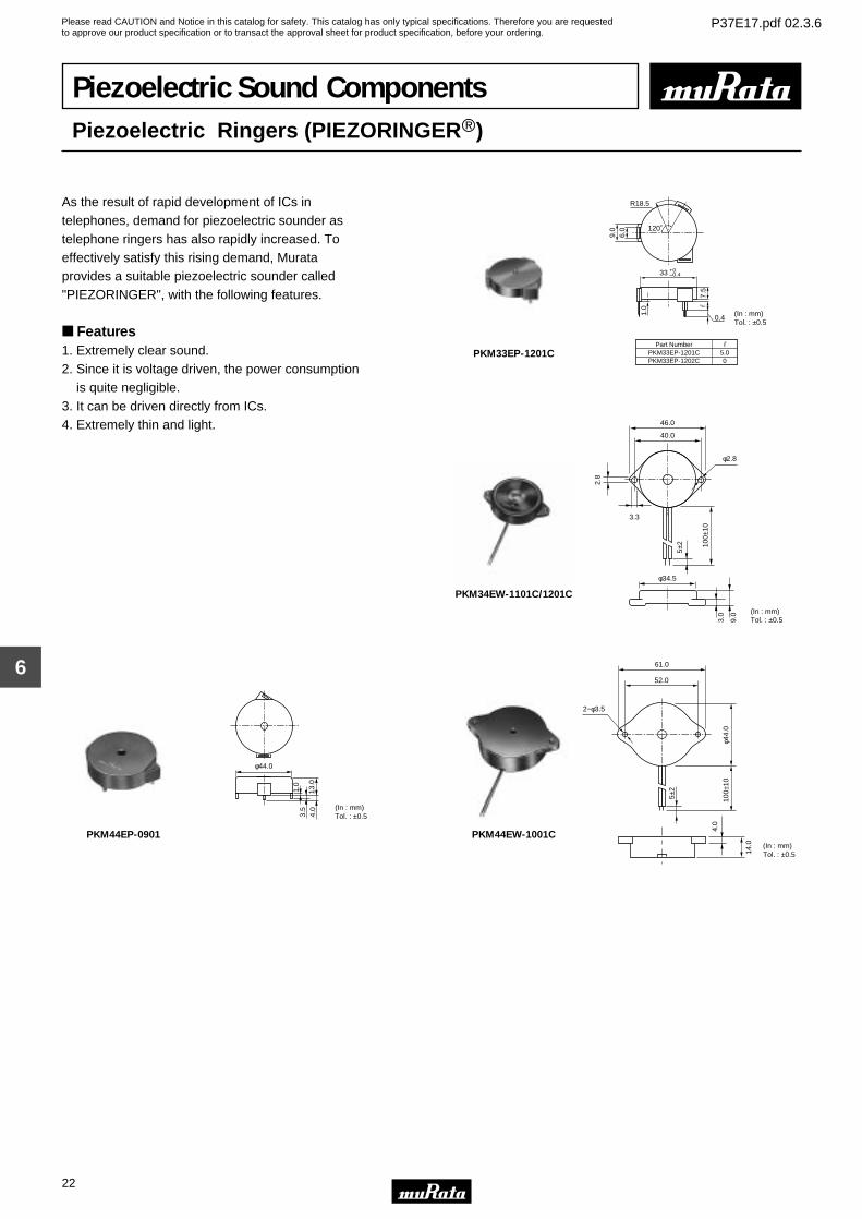
As the result of rapid development of ICs in telephones, demand for piezoelectric sounder as telephone ringers has also rapidly increased. To effectively satisfy this rising demand, Murata provides a suitable piezoelectric sounder called "PIEZORINGER", with the following features.
Features1. Extremely clear sound.2. Since it is voltage driven, the power consumption is quite negligible.3. It can be driven directly from ICs.4. Extremely thin and light.
1.0
0.4
9.0
6.0
7.5
R18.5
120˚
(In : mm)Tol. : ±0.5
Part NumberPKM33EP-1201CPKM33EP-1202C
5.00
33 +0–0.4
PKM33EP-1201C
φ34.5
3.0
9.0
100±
10
5±2
3.3
2.8
40.0
46.0
φ2.8
(In : mm)Tol. : ±0.5
PKM34EW-1101C/1201C
φ44.0
4.0
13.0
3.5
1.0
(In : mm)Tol. : ±0.5
PKM44EP-0901
4.0
φ44.
0
61.0
52.0
100±
10
14.0
2−φ3.5
(In : mm)Tol. : ±0.5
5±2
PKM44EW-1001C
Please read CAUTION and Notice in this catalog for safety. This catalog has only typical specifications. Therefore you are requestedto approve our product specification or to transact the approval sheet for product specification, before your ordering.
P37E17.pdf 02.3.6
23
6
Pin Type
Part NumberSound
Pressure Level(dB)
Sound PressureLevel(Ref. only)
(dB)
OperatingVoltage Range
(Vp-p)
Capacitance(nF)
OperatingTemp. Range
StorageTemp. Range
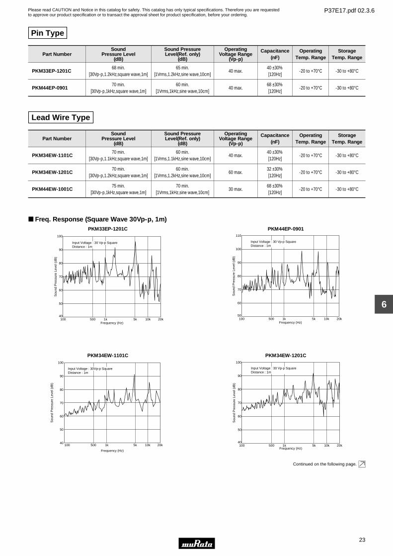
PKM33EP-1201C68 min.
[30Vp-p,1.2kHz,square wave,1m]65 min.
[1Vrms,1.2kHz,sine wave,10cm]40 max.
40 ±30%[120Hz]
-20 to +70°C -30 to +80°C
PKM44EP-090170 min.
[30Vp-p,1kHz,square wave,1m]60 min.
[1Vrms,1kHz,sine wave,10cm]40 max.
68 ±30%[120Hz]
-20 to +70°C -30 to +80°C
Lead Wire Type
Part NumberSound
Pressure Level(dB)
Sound PressureLevel(Ref. only)
(dB)
OperatingVoltage Range
(Vp-p)
Capacitance(nF)
OperatingTemp. Range
StorageTemp. Range
PKM34EW-1101C70 min.
[30Vp-p,1.1kHz,square wave,1m]60 min.
[1Vrms,1.1kHz,sine wave,10cm]40 max.
40 ±30%[120Hz]
-20 to +70°C -30 to +80°C
PKM34EW-1201C70 min.
[30Vp-p,1.2kHz,square wave,1m]60 min.
[1Vrms,1.2kHz,sine wave,10cm]60 max.
32 ±30%[120Hz]
-20 to +70°C -30 to +80°C
PKM44EW-1001C75 min.
[30Vp-p,1kHz,square wave,1m]70 min.
[1Vrms,1kHz,sine wave,10cm]30 max.
68 ±30%[120Hz]
-20 to +70°C -30 to +80°C
Freq. Response (Square Wave 30Vp-p, 1m)PKM33EP-1201C
Sou
nd P
ress
ure
Leve
l (dB
)
40
50
Frequency (Hz)100 500 1k 5k 10k 20k
60
70
80
90
100
Input Voltage : 30 Vp-p SquareDistance : 1m
PKM44EP-0901S
ound
Pre
ssur
e Le
vel (
dB)
50
60
Frequency (Hz)100 500 1k 5k 10k 20k
70
80
90
100
110
Input Voltage : 30 Vp-p SquareDistance : 1m
PKM34EW-1101C
40
50
60
70
80
90
100
100 500 1k 5k 10k 20k
Sou
nd P
ress
ure
Leve
l (dB
)
Frequency (Hz)
Input Voltage : 30Vp-p SquareDistance : 1m
PKM34EW-1201C
Sou
nd P
ress
ure
Leve
l (dB
)
40
50
Frequency (Hz)100 500 1k 5k 10k 20k
60
70
80
90
100
Input Voltage : 30 Vp-p SquareDistance : 1m
Continued on the following page.
Please read CAUTION and Notice in this catalog for safety. This catalog has only typical specifications. Therefore you are requestedto approve our product specification or to transact the approval sheet for product specification, before your ordering.
P37E17.pdf 02.3.6
24
6
Continued from the preceding page.
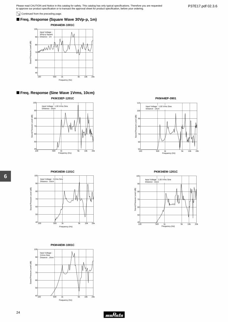
Freq. Response (Square Wave 30Vp-p, 1m)PKM44EW-1001C
40
50
60
70
80
90
100
100 500 1k 5k 10k 20k
Input Voltage : 30Vp-p SquareDistance : 1m
Sou
nd P
ress
ure
Leve
l (dB
)
Frequency (Hz)
Freq. Response (Sine Wave 1Vrms, 10cm)PKM33EP-1201C
Sou
nd P
ress
ure
Leve
l (dB
)
40
50
Frequency (Hz)100 500 1k 5k 10k 20k
60
70
80
90
100
Input Voltage : 1.00 Vrms SineDistance : 10cm
PKM44EP-0901
Sou
nd P
ress
ure
Leve
l (dB
)
50
60
Frequency (Hz)100 500 1k 5k 10k 20k
70
80
90
100
110
Input Voltage : 1.00 Vrms SineDistance : 10cm
PKM34EW-1101C
40
50
60
70
80
90
100
100 500 1k 5k 10k 20k
Input Voltage : 1Vrms SineDistance : 10cm
Sou
nd P
ress
ure
Leve
l (dB
)
Frequency (Hz)
PKM34EW-1201C
Sou
nd P
ress
ure
Leve
l (dB
)
40
50
Frequency (Hz)100 500 1k 5k 10k 20k
60
70
80
90
100
Input Voltage : 1.00 Vrms SineDistance : 10cm
PKM44EW-1001C
40
50
60
70
80
90
100
100 500 1k 5k 10k 20k
Sou
nd P
ress
ure
Leve
l (dB
)
Frequency (Hz)
Input Voltage : 1Vrms SineDistance : 10cm
Please read CAUTION and Notice in this catalog for safety. This catalog has only typical specifications. Therefore you are requestedto approve our product specification or to transact the approval sheet for product specification, before your ordering.
P37E17.pdf 02.3.6
Piezoelectric Ringers (PIEZORINGERr) Notice
25
6
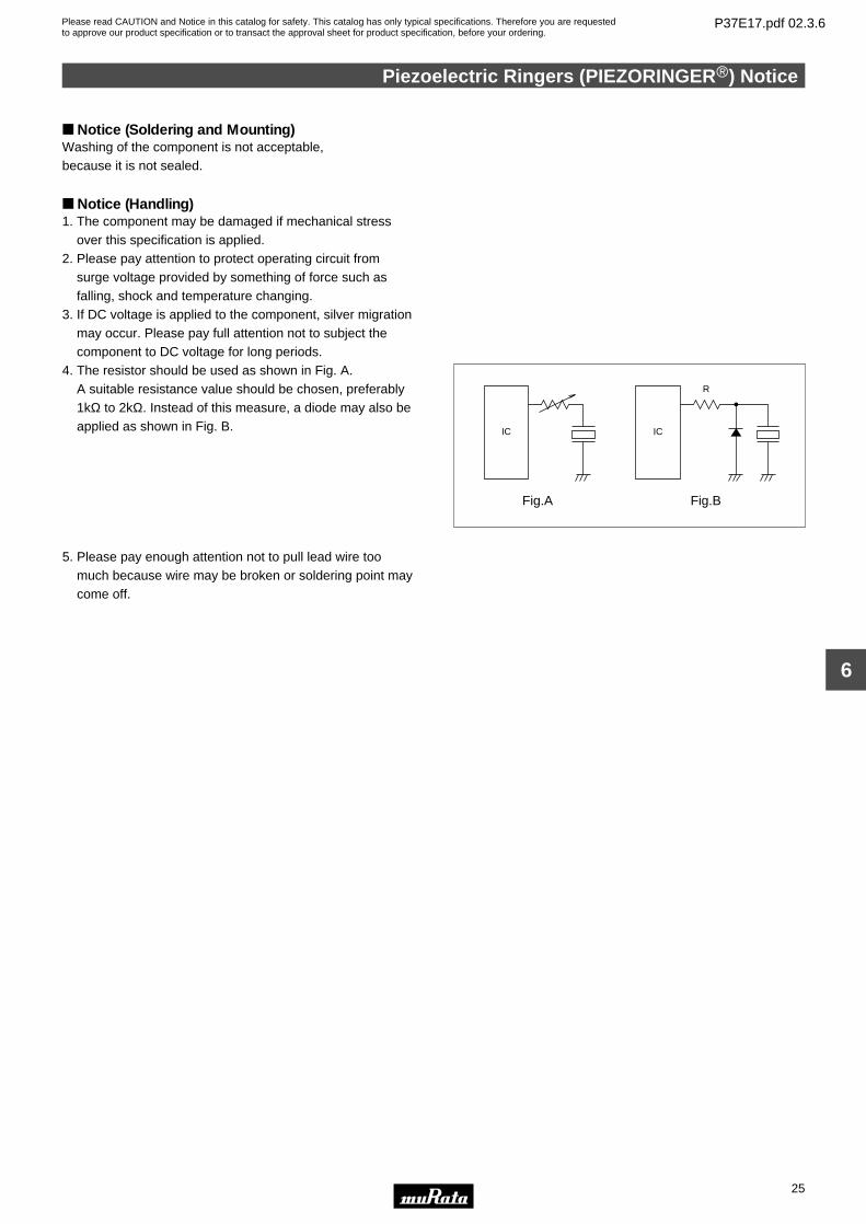
Notice (Soldering and Mounting)Washing of the component is not acceptable, because it is not sealed.
Notice (Handling)1. The component may be damaged if mechanical stress
over this specification is applied.2. Please pay attention to protect operating circuit from
surge voltage provided by something of force such as falling, shock and temperature changing.
3. If DC voltage is applied to the component, silver migration may occur. Please pay full attention not to subject the component to DC voltage for long periods.
4. The resistor should be used as shown in Fig. A. A suitable resistance value should be chosen, preferably
1kΩ to 2kΩ. Instead of this measure, a diode may also be applied as shown in Fig. B.
5. Please pay enough attention not to pull lead wire too much because wire may be broken or soldering point may come off.
IC
Fig.A
IC
Fig.B
R
Please read CAUTION and Notice in this catalog for safety. This catalog has only typical specifications. Therefore you are requestedto approve our product specification or to transact the approval sheet for product specification, before your ordering.
P37E17.pdf 02.3.6
26
7
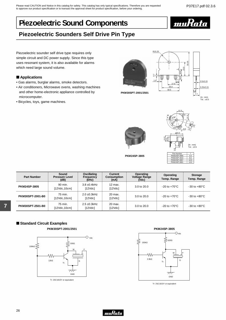
Piezoelectric Sound ComponentsPiezoelectric Sounders Self Drive Pin Type
Piezoelectric sounder self drive type requires only simple circuit and DC power supply. Since this type uses resonant system, it is also available for alarms which need large sound volume.
Applications• Gas alarms, burglar alarms, smoke detectors.• Air conditioners, Microwave ovens, washing machines and other home-electronic appliance controlled by microcomputer.• Bicycles, toys, game machines.
R15.25
1.0
0.7 10
.0
23.0
33.2
5
4.0
30.5
25.0
17.55.0
7.7
0.5±0.15
0.25±0.15
5.2
(In : mm)Tol. : ±0.5
PKM30SPT-2001/2501
(In : mm)Tol. : ±0.5
12.3
11.3
4
58.5
18˚
R14.2
130˚
φ24.0
11.0
8.3
3.5
G
F
M
Part NumberPKM24SP-3805PKM24SP-3810PKM24SP-3807PKM24SP-3801
4.08.0
12.014.0
PKM24SP-3805
Part NumberSound
Pressure Level(dB)
OscillatingFrequency
(kHz)
CurrentConsumption
(mA)
OperatingVoltage Range
(Vdc)
OperatingTemp. Range
StorageTemp. Range
PKM24SP-380590 min.
[12Vdc,10cm]3.8 ±0.4kHz
[12Vdc]12 max.[12Vdc]
3.0 to 20.0 -20 to +70°C -30 to +80°C
PKM30SPT-2001-B075 min.
[12Vdc,10cm]2.0 ±0.3kHz
[12Vdc]20 max.[12Vdc]
3.0 to 20.0 -20 to +70°C -30 to +80°C
PKM30SPT-2501-B075 min.
[12Vdc,10cm]2.5 ±0.3kHz
[12Vdc]20 max.[12Vdc]
3.0 to 20.0 -20 to +70°C -30 to +80°C
Standard Circuit ExamplesPKM30SPT-2001/2501
M F
12kΩ G
330Ω100kΩ
Vdc
Tr.
GND
Tr: 2SC1815Y or equivalent
PKM24SP-3805
Vdc
620Ω150kΩ
3.9kΩTr.
GND
M F
G
Tr: 2SC1815Y or equivalent
Please read CAUTION and Notice in this catalog for safety. This catalog has only typical specifications. Therefore you are requestedto approve our product specification or to transact the approval sheet for product specification, before your ordering.
P37E17.pdf 02.3.6
Piezoelectric Sounders (Self Drive) Notice
27
7
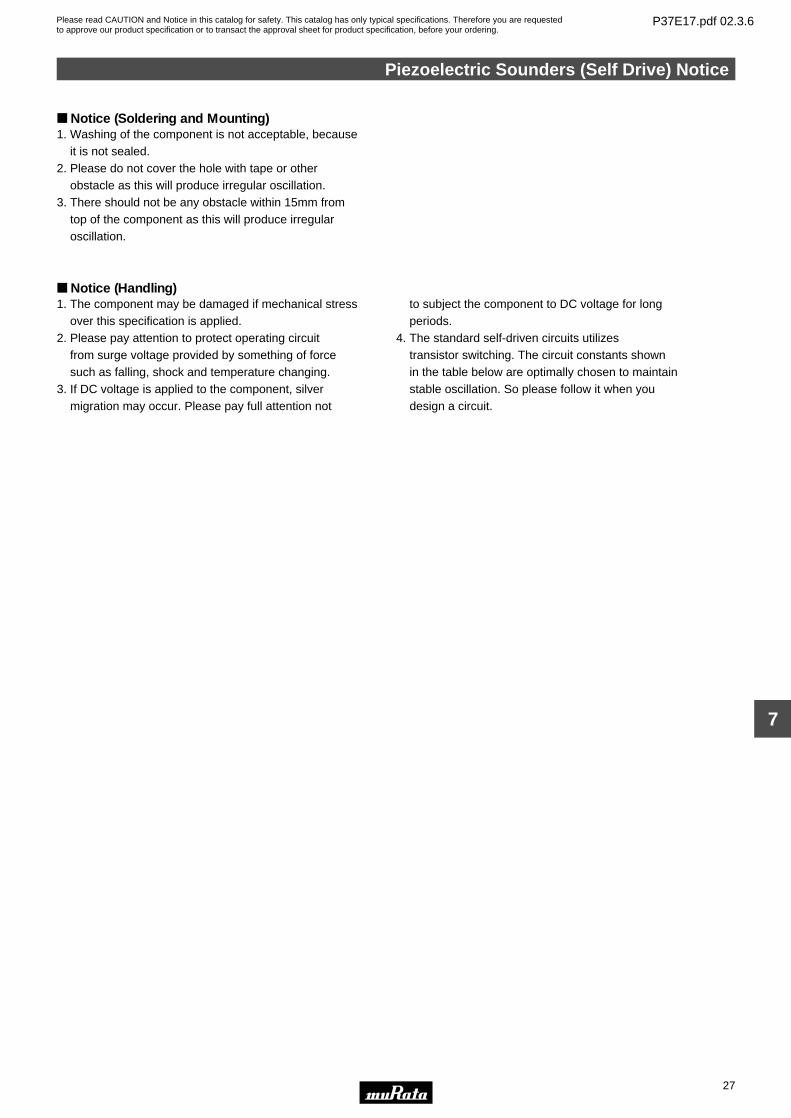
Notice (Soldering and Mounting)1. Washing of the component is not acceptable, because it is not sealed.2. Please do not cover the hole with tape or other obstacle as this will produce irregular oscillation.3. There should not be any obstacle within 15mm from top of the component as this will produce irregular oscillation.
Notice (Handling)1. The component may be damaged if mechanical stress over this specification is applied.2. Please pay attention to protect operating circuit from surge voltage provided by something of force such as falling, shock and temperature changing.3. If DC voltage is applied to the component, silver migration may occur. Please pay full attention not
to subject the component to DC voltage for long periods.4. The standard self-driven circuits utilizes transistor switching. The circuit constants shown in the table below are optimally chosen to maintain stable oscillation. So please follow it when you design a circuit.
Please read CAUTION and Notice in this catalog for safety. This catalog has only typical specifications. Therefore you are requestedto approve our product specification or to transact the approval sheet for product specification, before your ordering.
P37E17.pdf 02.3.6
28
8
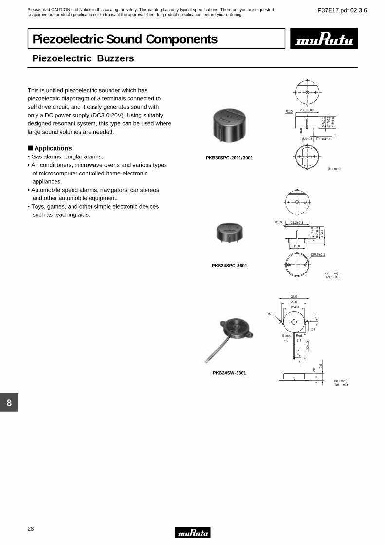
Piezoelectric Sound ComponentsPiezoelectric Buzzers
This is unified piezoelectric sounder which has piezoelectric diaphragm of 3 terminals connected to self drive circuit, and it easily generates sound with only a DC power supply (DC3.0-20V). Using suitably designed resonant system, this type can be used where large sound volumes are needed.
Applications• Gas alarms, burglar alarms.• Air conditioners, microwave ovens and various types of microcomputer controlled home-electronic appliances.• Automobile speed alarms, navigators, car stereos and other automobile equipment.• Toys, games, and other simple electronic devices such as teaching aids.
0.64±0.1
– +
φ30.3±0.3R1.0
4.5±
1.0
17.7
±0.3
0.7±
0.1
15.0±0.5
(In : mm)
PKB30SPC-2001/3001
0.7±
0.3
9.7±
0.3
4.5±
1
24.3±0.3
15.0
R1.0
0.6±0.1
(In : mm)Tol. : ±0.5
PKB24SPC-3601
9.5
34.0
29.0
φ24.0
2.2
2.7
φ2.2
100±
10
5±2
2.0
Black(–)
Red(+)
(In : mm)Tol. : ±0.5
PKB24SW-3301
Please read CAUTION and Notice in this catalog for safety. This catalog has only typical specifications. Therefore you are requestedto approve our product specification or to transact the approval sheet for product specification, before your ordering.
P37E17.pdf 02.3.6
29
8
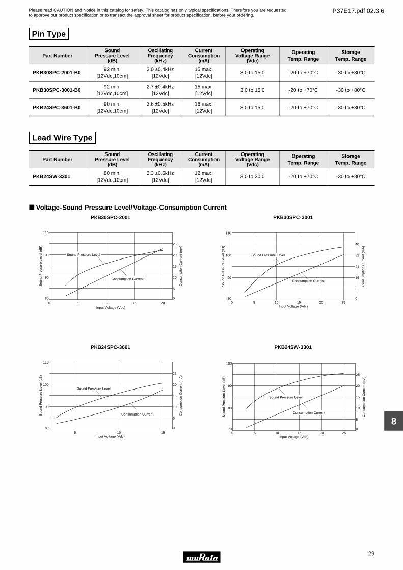
Pin Type
Part NumberSound
Pressure Level(dB)
OscillatingFrequency
(kHz)
CurrentConsumption
(mA)
OperatingVoltage Range
(Vdc)
OperatingTemp. Range
StorageTemp. Range
PKB30SPC-2001-B092 min.
[12Vdc,10cm]2.0 ±0.4kHz
[12Vdc]15 max.[12Vdc]
3.0 to 15.0 -20 to +70°C -30 to +80°C
PKB30SPC-3001-B092 min.
[12Vdc,10cm]2.7 ±0.4kHz
[12Vdc]15 max.[12Vdc]
3.0 to 15.0 -20 to +70°C -30 to +80°C
PKB24SPC-3601-B090 min.
[12Vdc,10cm]3.6 ±0.5kHz
[12Vdc]16 max.[12Vdc]
3.0 to 15.0 -20 to +70°C -30 to +80°C
Lead Wire Type
Part NumberSound
Pressure Level(dB)
OscillatingFrequency
(kHz)
CurrentConsumption
(mA)
OperatingVoltage Range
(Vdc)
OperatingTemp. Range
StorageTemp. Range
PKB24SW-330180 min.
[12Vdc,10cm]3.3 ±0.5kHz
[12Vdc]12 max.[12Vdc]
3.0 to 20.0 -20 to +70°C -30 to +80°C
Voltage-Sound Pressure Level/Voltage-Consumption Current PKB30SPC-2001
Input Voltage (Vdc)0 5 10 15 20
Sound Pressure Level
Consumption Current
Sou
nd P
ress
ure
Leve
l (dB
)
110
100
90
80
25
20
15
10
5
0
Con
sum
ptio
n C
urre
nt (
mA
)
PKB30SPC-3001S
ound
Pre
ssur
e Le
vel (
dB)
110
100
90
80
40
32
24
16
8
0
Input Voltage (Vdc)0 5 10 15 20 25
Con
sum
ptio
n C
urre
nt (
mA
)
Sound Pressure Level
Consumption Current
PKB24SPC-3601
Input Voltage (Vdc)5 10 15
Sound Pressure Level
Consumption CurrentSou
nd P
ress
ure
Leve
l (dB
)
110
100
90
80
20
15
25
10
5
0
Con
sum
ptio
n C
urre
nt (
mA
)
PKB24SW-3301
Sou
nd P
ress
ure
Leve
l (dB
)
100
90
80
70
25
20
15
10
5
0
Input Voltage (Vdc)0 5 10 15 20 25
Con
sum
ptio
n C
urre
nt (
mA
)
Sound Pressure Level
Consumption Current
Please read CAUTION and Notice in this catalog for safety. This catalog has only typical specifications. Therefore you are requestedto approve our product specification or to transact the approval sheet for product specification, before your ordering.
P37E17.pdf 02.3.6
Piezoelectric Buzzers Notice
30
8
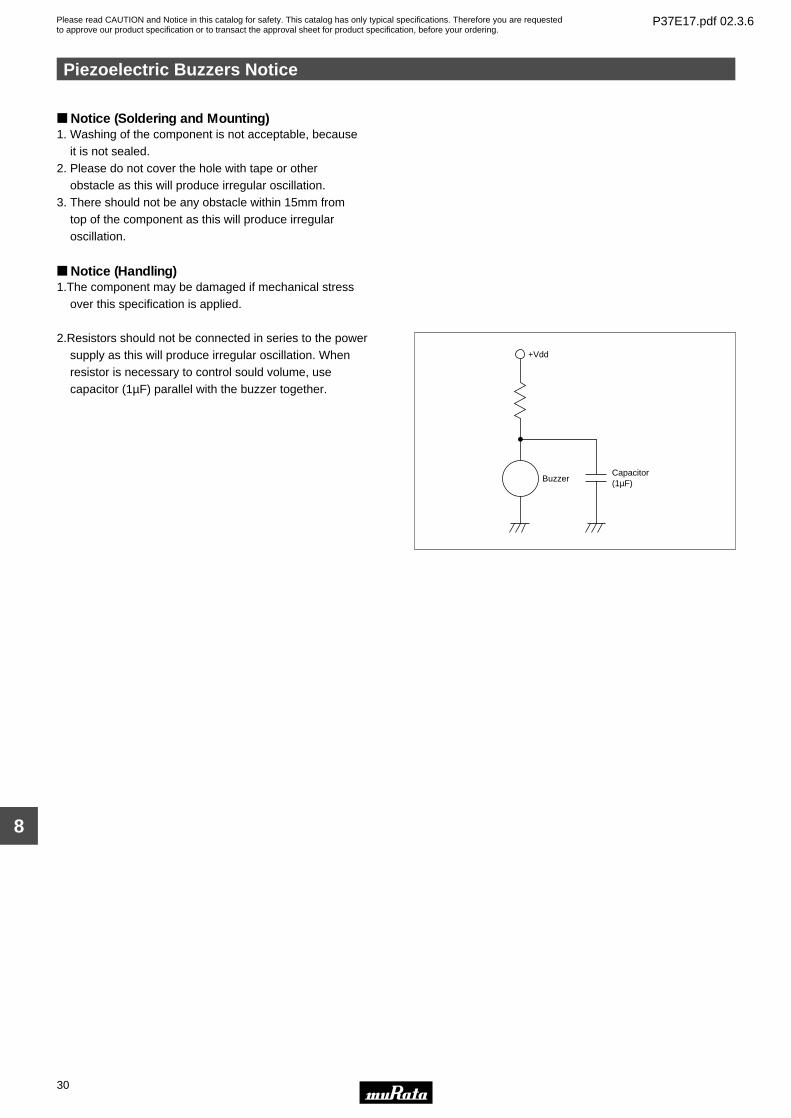
Notice (Soldering and Mounting)1. Washing of the component is not acceptable, because it is not sealed.2. Please do not cover the hole with tape or other obstacle as this will produce irregular oscillation.3. There should not be any obstacle within 15mm from top of the component as this will produce irregular oscillation.
Notice (Handling)1.The component may be damaged if mechanical stress
over this specification is applied.
2.Resistors should not be connected in series to the power supply as this will produce irregular oscillation. When resistor is necessary to control sould volume, use capacitor (1µF) parallel with the buzzer together.
+Vdd
BuzzerCapacitor(1µF)
Please read CAUTION and Notice in this catalog for safety. This catalog has only typical specifications. Therefore you are requestedto approve our product specification or to transact the approval sheet for product specification, before your ordering.
P37E17.pdf 02.3.6
31
9
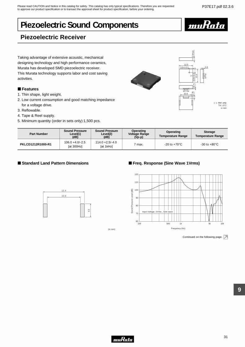
Piezoelectric Sound ComponentsPiezoelectric Receiver
Taking advantage of extensive acoustic, mechanical designing technology and high performance ceramics, Murata has developed SMD piezoelectric receiver.This Murata technology supports labor and cost saving activities.
Features1. Thin shape, light weight.2. Low current consumption and good matching impedance for a voltage drive.3. Reflowable.4. Tape & Reel supply.5. Minimum quantity (order in sets only):1,500 pcs.
2.0m
ax.
0.9
4.0
12.0
(0.7
)
(5.0)
10.0
(1.8
)
12.0
3.0+
/-0.
3
3.0+/-0.3
in mm
( ) : Ref. onlyTol. ±0.2
Part NumberSound Pressure
Level(1)(dB)
Sound PressureLevel(2)
(dB)
OperatingVoltage Range
(Vp-p)
OperatingTemperature Range
StorageTemperature Range
PKLCD1212R1000-R1106.0 +4.0/-2.5
[at 300Hz]114.0 +2.5/-4.0
[at 1kHz]7 max. -20 to +70°C -30 to +80°C
Standard Land Pattern Dimensions
10.0
12.4
4.0
(in mm)
Freq. Response (Sine Wave 1Vrms)
60
70
80
90
100
110
120
100 1k 10k5k500
Frequency (Hz)
Sou
nd P
ress
ure
Leve
l (dB
)
Input Voltage: 1Vrms , Sine wave
Continued on the following page.
Please read CAUTION and Notice in this catalog for safety. This catalog has only typical specifications. Therefore you are requestedto approve our product specification or to transact the approval sheet for product specification, before your ordering.
P37E17.pdf 02.3.6
32
9
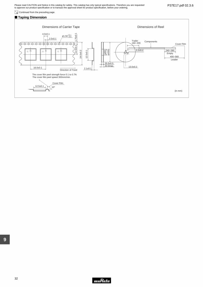
Continued from the preceding page.
Taping Dimension
Dimensions of Carrier Tape Dimensions of Reel
(in mm)
24.0
±0.2
11.5
±0.1
1.75
±0.1+0.1ø1.50 -0.0
2.0±0.1
4.0±0.1
16.0±0.1
12.5
±0.1
2.1±0.1
12.5±0.1
Direction of Feed
Cover Film
The cover film peel strength force 0.1 to 0.7NThe cover film peel speed 300mm/min.
10°
13.0±0.233.5max.
240~2802.2±0.2
ComponentsTrailer160~200
Empty
Leader
(ø80
)
(ø33
0)
400~560
25.5±0.5
Cover Film
Please read CAUTION and Notice in this catalog for safety. This catalog has only typical specifications. Therefore you are requestedto approve our product specification or to transact the approval sheet for product specification, before your ordering.
P37E17.pdf 02.3.6
Piezoelectric Receiver Circuit/Notice
33
9
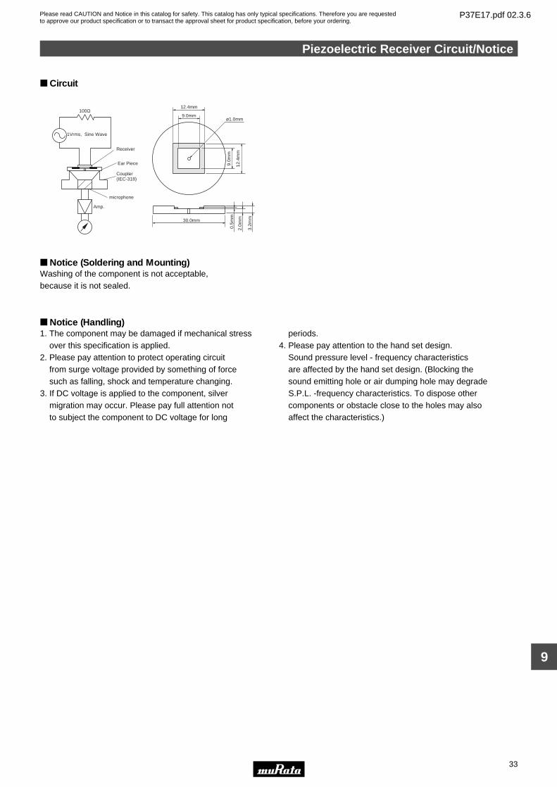
Circuit
ø1.0mm
100Ω
microphone
1Vrms, Sine Wave
Amp.
Coupler (IEC-318)
Ear Piece
Receiver
9.0m
m
9.0mm
30.0mm
3.2m
m
0.5m
m
12.4mm
12.4
mm
2.0m
m
Notice (Soldering and Mounting)Washing of the component is not acceptable, because it is not sealed.
Notice (Handling)1. The component may be damaged if mechanical stress over this specification is applied. 2. Please pay attention to protect operating circuit from surge voltage provided by something of force such as falling, shock and temperature changing.3. If DC voltage is applied to the component, silver migration may occur. Please pay full attention not to subject the component to DC voltage for long
periods.4. Please pay attention to the hand set design. Sound pressure level - frequency characteristics are affected by the hand set design. (Blocking the sound emitting hole or air dumping hole may degrade S.P.L. -frequency characteristics. To dispose other components or obstacle close to the holes may also affect the characteristics.)
Please read CAUTION and Notice in this catalog for safety. This catalog has only typical specifications. Therefore you are requestedto approve our product specification or to transact the approval sheet for product specification, before your ordering.
P37E17.pdf 02.3.6
34
10
Piezoelectric Sound ComponentsPiezoelectric Speakers (CERAMITONEr)
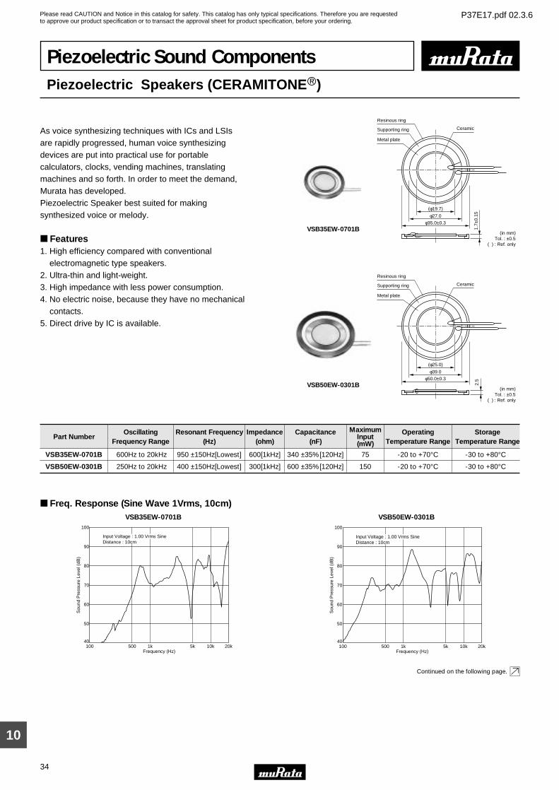
As voice synthesizing techniques with ICs and LSIs are rapidly progressed, human voice synthesizing devices are put into practical use for portable calculators, clocks, vending machines, translating machines and so forth. In order to meet the demand,Murata has developed.Piezoelectric Speaker best suited for making synthesized voice or melody.
Features1. High efficiency compared with conventional electromagnetic type speakers.2. Ultra-thin and light-weight.3. High impedance with less power consumption.4. No electric noise, because they have no mechanical contacts.5. Direct drive by IC is available.
(φ19.7)
φ27.0
1.7±
0.15
Metal plate
Supporting ring Ceramic
Resinous ring
φ35.0±0.3
(in mm)Tol. : ±0.5
( ) : Ref. only
VSB35EW-0701B
Metal plate
Supporting ring Ceramic
Resinous ring
(in mm)Tol. : ±0.5
( ) : Ref. only
2.5
(φ25.0)
φ39.0
φ50.0±0.3
VSB50EW-0301B
Part NumberOscillating
Frequency RangeResonant Frequency
(Hz)Impedance
(ohm)Capacitance
(nF)
MaximumInput(mW)
OperatingTemperature Range
StorageTemperature Range
VSB35EW-0701B 600Hz to 20kHz 950 ±150Hz[Lowest] 600[1kHz] 340 ±35%[120Hz] 75 -20 to +70°C -30 to +80°C
VSB50EW-0301B 250Hz to 20kHz 400 ±150Hz[Lowest] 300[1kHz] 600 ±35%[120Hz] 150 -20 to +70°C -30 to +80°C
Freq. Response (Sine Wave 1Vrms, 10cm)VSB35EW-0701B
Sou
nd P
ress
ure
Leve
l (dB
)
100
90
80
70
60
50
4020k
Frequency (Hz)100 500 1k 10k5k
Input Voltage : 1.00 Vrms SineDistance : 10cm
VSB50EW-0301B
Sou
nd P
ress
ure
Leve
l (dB
)
100
90
80
70
60
50
4020k
Frequency (Hz)100 500 1k 10k5k
Input Voltage : 1.00 Vrms SineDistance : 10cm
Continued on the following page.
Please read CAUTION and Notice in this catalog for safety. This catalog has only typical specifications. Therefore you are requestedto approve our product specification or to transact the approval sheet for product specification, before your ordering.
P37E17.pdf 02.3.6
35
10
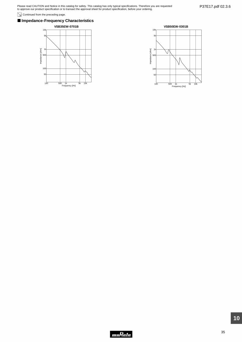
Continued from the preceding page.
Impedance-Frequency CharacteristicsVSB35EW-0701B
Impe
danc
e [o
hm]
10k
1k
500
100
50
Frequency [Hz]100 500 1k 10k5k
5k
VSB50EW-0301B
Impe
danc
e [o
hm]
10k
1k
500
100
50
Frequency [Hz]100 500 1k 10k5k
5k
Please read CAUTION and Notice in this catalog for safety. This catalog has only typical specifications. Therefore you are requestedto approve our product specification or to transact the approval sheet for product specification, before your ordering.
P37E17.pdf 02.3.6
Piezoelectric Speakers (CERAMITONEr) Notice
36
10
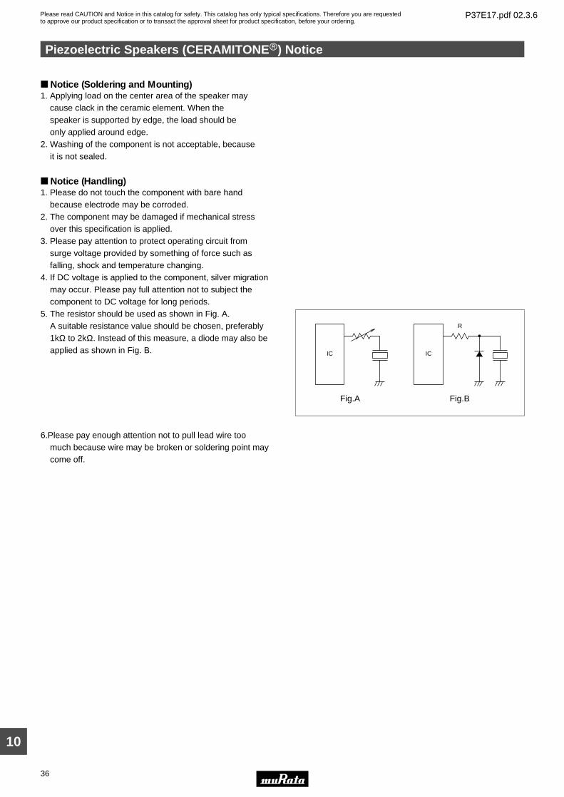
Notice (Soldering and Mounting)1. Applying load on the center area of the speaker may cause clack in the ceramic element. When the speaker is supported by edge, the load should be only applied around edge.2. Washing of the component is not acceptable, because it is not sealed.
Notice (Handling)1. Please do not touch the component with bare hand
because electrode may be corroded.2. The component may be damaged if mechanical stress
over this specification is applied.3. Please pay attention to protect operating circuit from
surge voltage provided by something of force such as falling, shock and temperature changing.
4. If DC voltage is applied to the component, silver migration may occur. Please pay full attention not to subject the component to DC voltage for long periods.
5. The resistor should be used as shown in Fig. A. A suitable resistance value should be chosen, preferably
1kΩ to 2kΩ. Instead of this measure, a diode may also be applied as shown in Fig. B.
6.Please pay enough attention not to pull lead wire too much because wire may be broken or soldering point may come off.
IC
Fig.A
IC
Fig.B
R
Please read CAUTION and Notice in this catalog for safety. This catalog has only typical specifications. Therefore you are requestedto approve our product specification or to transact the approval sheet for product specification, before your ordering.
P37E17.pdf 02.3.6
1
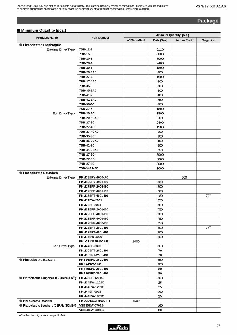
Minimum Quantity
o Piezoelectric Sounders
o Piezoelectric Buzzers
o Piezoelectric Ringers (PIEZORINGERr)
Self Drive Type
Self Drive Type
PKM24SP-3805 360PKM30SPT-2001-B0 70PKM30SPT-2501-B0 70
External Drive Type PKM13EPY-4000-A0 500
70*
75*
PKM13EPY-4002-B0 330PKM17EPP-2002-B0 200PKM17EPP-4001-B0 200PKM17EPT-4001-B0 180PKM17EW-2001 250PKM22EP-2001 360PKM22EPP-2001-B0 750PKM22EPP-4001-B0 900PKM22EPP-4005-B0 750PKM22EPP-4007-B0 750PKM22EPT-2001-B0 300PKM22EPT-4001-B0 300PKM17EW-4000 500PKLCS1212E4001-R1 1000
PKB24SPC-3601-B0 650PKB24SW-3301 200PKB30SPC-2001-B0 80PKB30SPC-3001-B0 80PKM33EP-1201C 300PKM34EW-1101C 25PKM34EW-1201C 25PKM44EP-0901 160
25PKM44EW-1001C
Products Name Part NumberMinimum Quantity (pcs.)
Bulk (Box)ø330mmReel Ammo Pack Magazine
o Piezoelectric DiaphragmsExternal Drive Type 7BB-12-9 5120
7BB-15-6 80007BB-20-3 30007BB-20-4 24007BB-20-6 18007BB-20-6A0 6007BB-27-4 15007BB-27-4A0 6007BB-35-3 8007BB-35-3A0 4007BB-41-2 4007BB-41-2A0 2507BB-50M-1 6007SB-20-7 18007BB-20-6C 18007BB-20-6CA0 6007BB-27-3C 24007BB-27-4C 15007BB-27-4CA0 6007BB-35-3C 8007BB-35-3CA0 4007BB-41-2C 6007BB-41-2CA0 2507NB-27-2C 30007NB-27-3C 30007NB-27-4C 30007SB-34R7-3C 1600
o Piezoelectric Speakers (CERAMITONEr) VSB35EW-0701B 160o Piezoelectric Receiver PKLCD1212R1000-R1 1500
VSB50EW-0301B 80
*The last two digits are changed to M0.
Minimum Quantity (pcs.)
Package
37
10
Head Office2-26-10, Tenjin Nagaokakyo-shi, Kyoto 617-8555, Japan Phone:81-75-951-9111
International Division3-29-12, Shibuya, Shibuya-ku, Tokyo 150-0002, Japan Phone:81-3-5469-6123 Fax:81-3-5469-6155 E-mail:[email protected]
http://www.murata.co.jp/products/
Please read CAUTION and Notice in this catalog for safety. This catalog has only typical specifications. Therefore you are requestedto approve our product specification or to transact the approval sheet for product specification, before your ordering.
P37E17.pdf 02.3.6
Note:1. Export Control
<For customers outside Japan>Murata products should not be used or sold for use in the development, production, stockpiling or utilization of any conventional weapons or mass-destructiveweapons (nuclear weapons, chemical or biological weapons, or missiles), or any other weapons.<For customers in Japan>For products which are controlled items subject to the “Foreign Exchange and Foreign Trade Law” of Japan, the export license specified by the law is requiredfor export.
2. Please contact our sales representatives or product engineers before using our products listed in this catalog for the applications listed below which requireespecially high reliability for the prevention of defects which might directly cause damage to the third party's life, body or property, or when intending to use oneof our products for other applications than specified in this catalog.q Aircraft equipmentw Aerospace equipmente Undersea equipmentr Power plant equipmentt Medical equipmenty Transportation equipment (vehicles, trains, ships, etc.)u Traffic signal equipmenti Disaster prevention / crime prevention equipmento Data-processing equipment!0 Application of similar complexity and/or reliability requirements to the applications listed in the above
3. Product specifications in this catalog are as of January 2002. They are subject to change or our products in it may be discontinued without advance notice.Please check with our sales representatives or product engineers before your ordering. If there are any questions, please contact our sales representatives orproduct engineers.
4. Please read CAUTION and Notice in this catalog for safety. This catalog has only typical specifications. Therefore you are requested to approve our productspecification or to transact the approval sheet for product specification, before your ordering.
5. Please note that unless otherwise specified, we shall assume no responsibility whatsoever for any conflict or dispute that may occur in connection with the effectof our and/or third party's intellectual property rights and other related rights in consideration of your using our products and/or information described orcontained in our catalogs. In this connection, no representation shall be made to the effect that any third parties are authorized to use the rights mentionedabove under licenses without our consent.
6. None of ozone depleting substances (ODS) under the Montreal Protocol is used in manufacturing process of us.