PIEZOCERAMIC BUZZERS - Oxygen Electronics · an increasing number of piezoceramic buzzers are now...
20
KE11021-1312-005 PIEZOCERAMIC BUZZERS Contents Page ¡Introduction ................................................ 2 ¡Makeup of piezoceramic buzzer products ................................................................... 2 ¡Piezoceramic diaphragms .......................... 3 ¡Piezoceramic sounders .............................. 4 ¡Piezoceramic buzzers(EB-type) ................. 9 ¡Piezoceramic buzzers(U-type) ................. 15 ¡How to use piezoceramic buzzers ........... 17 ¡Piezoceramic buzzer measurement method ..................................................... 18 ¡Standard conditions for reliability tests .... 19 ¡ Caution ................................................ 19
Transcript of PIEZOCERAMIC BUZZERS - Oxygen Electronics · an increasing number of piezoceramic buzzers are now...
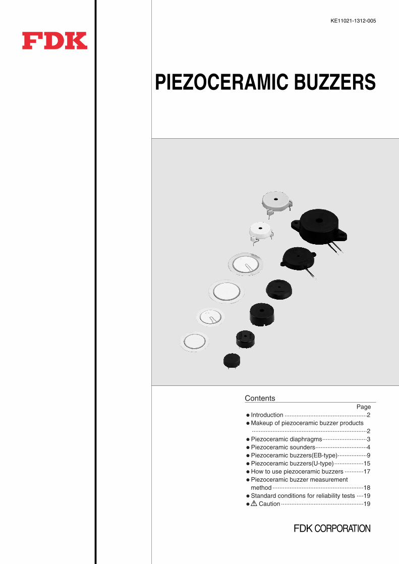
KE11021-1312-005
PIEZOCERAMIC BUZZERS
ContentsPage
¡Introduction ................................................2¡Makeup of piezoceramic buzzer products
...................................................................2¡Piezoceramic diaphragms..........................3¡Piezoceramic sounders..............................4¡Piezoceramic buzzers(EB-type).................9¡Piezoceramic buzzers(U-type).................15¡How to use piezoceramic buzzers ...........17¡Piezoceramic buzzer measurement
method .....................................................18¡Standard conditions for reliability tests ....19¡ Caution ................................................19
2http://www.fdk.co.jp
IntroductionFDK piezoceramic buzzers generate soundthrough the bending vibrations of a thin metalplate adhered to a piezoceramic disc. Thesebuzzers feature a low power consumption, asafe, spark-free and non-contact structure, anda small size and light weight for an easy mounting to printed circuit boards. As a result,an increasing number of piezoceramic buzzersare now used to generate an artificial voice incombination with voice synthesizing ICs. Toproduce high-quality piezoceramic buzzers,FDK has capitalized on many years ofpiezoceramics production and outstandingceramic processing technologies and thin filmforming techniques. By adding a sophisticatedaudio know-how to this manufacturing expertise,FDK offers a large array of electronic tonegenerating products, such as piezoceramicdiaphragms, sounders and buzzers, to meetloud sound outputs, wide frequency ranges, andmany other requirements.
Features Use of high-performance piezoceramic elements to meet loud sound
volume and wide frequency range needs. High quality achieved by integrated in-house production, from
piezoceramic materials to buzzers. Clear, pleasant electronic tone. Reliable, effective operation in a wide variety of equipment and ambient
conditions. A wide, convenient selection from elements to complete buzzer products.
Applications Consumer electronic appliances: Refrigerators, microwave ovens,
washing machines, electric fans, VCRs, air conditioners, bath heaters,sewing machines
Clocks and toys: Digital clocks and watches, alarm clocks, calculators,game machines, greeting cards
Office equipment: Photocopiers, typewriters, cash registers, personalcomputers, facsimiles
Automotive instruments: Speed alarms; reverse drive buzzers; light,oil, battery, seatbelt check sounders, keyless entry
Safety and security equipment: Fire alarms, burglar alarms, gasleakage alarms
Other electronic equipment: Vending machines, automatic controllers,bicycle horns, telephones, cameras
Makeup of piezoceramic buzzer products
Piezoceramic buzzers(EB-,U-types)
Pie
zoce
ram
ic b
uzze
r pr
oduc
ts
Piezoceramic diaphragms
Piezoceramic sounders
Self-drive(EF-,OSF-types)
External-drive(EE-type)
External-drive(EE-type)
Self-drive(EF-type)
qe
w
q e
r
w
r
q Electrode (silver)w Ceramic disce Adhesiver Metal plate (brass,stainless steel)
CasingPiezoceramic diaphragm
Lead wire
CasingPot-type piezoceramic diaphragm
Circuit board
Lead wire to power source
Casing
Piezoceramic diaphragm
Lead pin to power source
FPlease refer to page 17 for the difference between external-drive type and self-drive type.
3http://www.fdk.co.jp
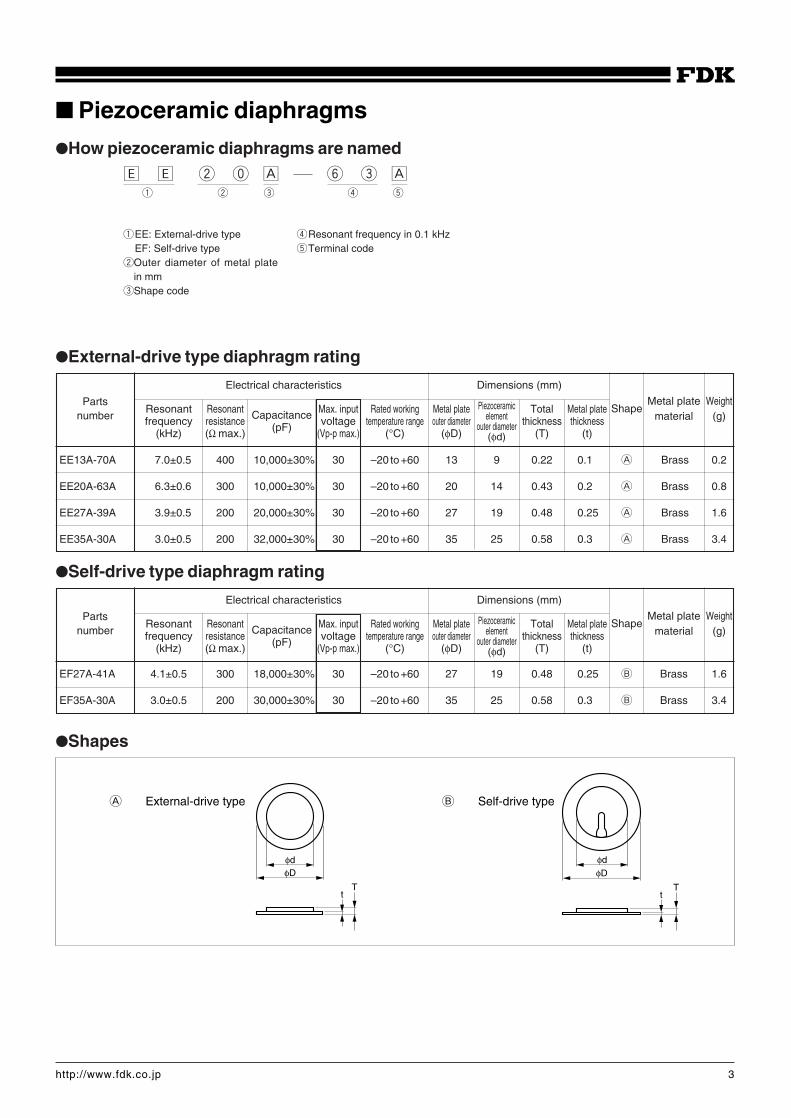
Piezoceramic diaphragms
qEE: External-drive typeEF: Self-drive type
wOuter diameter of metal platein mm
eShape code
rResonant frequency in 0.1 kHztTerminal code
External-drive type diaphragm rating
EE13A-70A 7.0±0.5 400 10,000±30% 30 –20 to +60 13 9 0.22 0.1 A Brass 0.2
EE20A-63A 6.3±0.6 300 10,000±30% 30 –20 to +60 20 14 0.43 0.2 A Brass 0.8
EE27A-39A 3.9±0.5 200 20,000±30% 30 –20 to +60 27 19 0.48 0.25 A Brass 1.6
EE35A-30A 3.0±0.5 200 32,000±30% 30 –20 to +60 35 25 0.58 0.3 A Brass 3.4
Partsnumber
Electrical characteristics Dimensions (mm)
Metal plate WeightShape
material (g)Resonant Resonant Max. input Rated working Metal plate Total Metal platefrequency resistance Capacitance voltage temperature range outer diameter thickness thickness
(kHz) (Ω max.) (pF) (Vp-p max.) (°C) (φD) (T) (t)
Self-drive type diaphragm rating
EF27A-41A 4.1±0.5 300 18,000±30% 30 –20 to +60 27 19 0.48 0.25 B Brass 1.6
EF35A-30A 3.0±0.5 200 30,000±30% 30 –20 to +60 35 25 0.58 0.3 B Brass 3.4
Partsnumber
Electrical characteristics Dimensions (mm)
Metal plate WeightShape
material (g)
Shapes
φdφD
Tt
φdφD
Tt
A External-drive type B Self-drive type
Piezoceramicelement
outer diameter(φd)
Piezoceramicelement
outer diameter(φd)
Resonant Resonant Max. input Rated working Metal plate Total Metal platefrequency resistance Capacitance voltage temperature range outer diameter thickness thickness
(kHz) (Ω max.) (pF) (Vp-p max.) (°C) (φD) (T) (t)
How piezoceramic diaphragms are named
‰ ‰ w p Å y e Åq w e r t
4http://www.fdk.co.jp
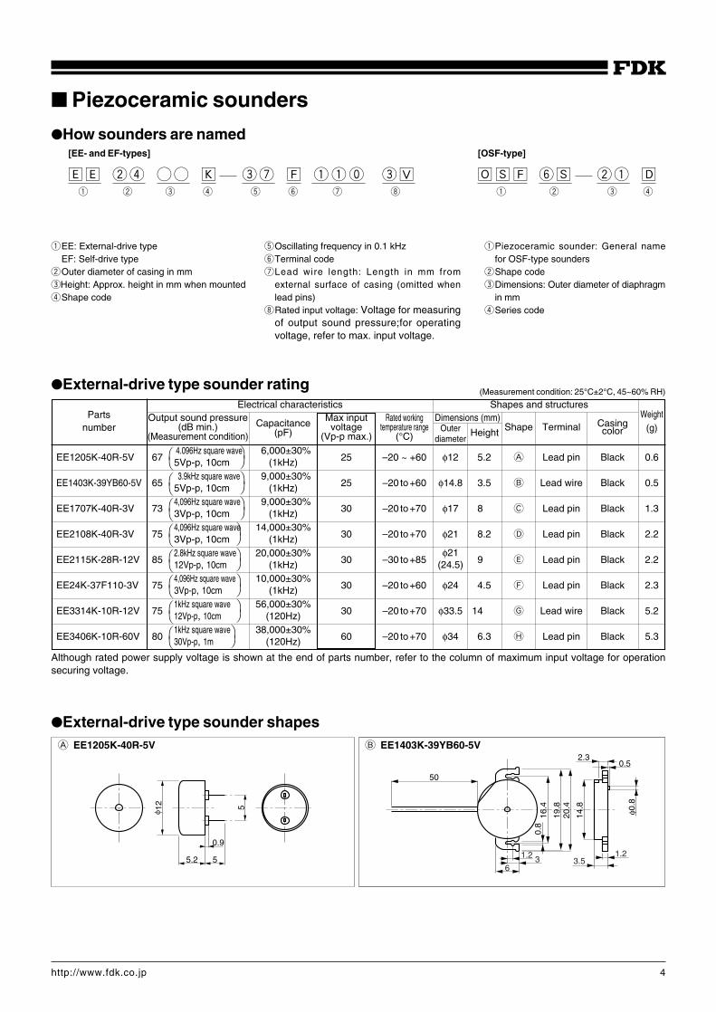
Piezoceramic sounders
qEE: External-drive typeEF: Self-drive type
wOuter diameter of casing in mmeHeight: Approx. height in mm when mountedrShape code
tOscillating frequency in 0.1 kHzyTerminal code uLead wire length: Length in mm from
external surface of casing (omitted whenlead pins)
iRated input voltage: Voltage for measuringof output sound pressure;for operatingvoltage, refer to max. input voltage.
qPiezoceramic sounder: General namefor OSF-type sounders
wShape codeeDimensions: Outer diameter of diaphragm
in mmrSeries code
External-drive type sounder rating
Partsnumber
Output sound pressure Capacitance Max input Rated working Dimensions (mm) Casing(dB min.) (pF) voltage temperature range Height Shape Terminal(Measurement condition) (Vp-p max.) (°C) color
Electrical characteristics Shapes and structuresWeight
(g)
EE1205K-40R-5V 67 25 –20 ~ +60 φ12 5.2 A Lead pin Black 0.6
EE1403K-39YB60-5V 65 25 –20 to +60 φ14.8 3.5 B Lead wire Black 0.5
EE1707K-40R-3V 73 30 –20 to +70 φ17 8 C Lead pin Black 1.3
EE2108K-40R-3V 75 30 –20 to +70 φ21 8.2 D Lead pin Black 2.2
EE2115K-28R-12V 85 30 –30 to +85 9 E Lead pin Black 2.2
EE24K-37F110-3V 75 30 –20 to +60 φ24 4.5 F Lead pin Black 2.3
EE3314K-10R-12V 75 30 –20 to +70 φ33.5 14 G Lead wire Black 5.2
EE3406K-10R-60V 80 60 –20 to +70 φ34 6.3 H Lead pin Black 5.3
4.096Hz square wave5Vp-p, 10cm
3.9kHz square wave5Vp-p, 10cm4,096Hz square wave3Vp-p, 10cm4,096Hz square wave3Vp-p, 10cm2.8kHz square wave12Vp-p, 10cm4,096Hz square wave3Vp-p, 10cm1kHz square wave12Vp-p, 10cm1kHz square wave30Vp-p, 1m
φ21(24.5)
16,000±30%(1kHz)
19,000±30%(1kHz)
19,000±30%(1kHz)
14,000±30%(1kHz)
20,000±30%(1kHz)
10,000±30%(1kHz)
56,000±30%(120Hz)
38,000±30%(120Hz)
(Measurement condition: 25°C±2°C, 45~60% RH)
Outerdiameter
How sounders are named[EE- and EF-types]
‰‰ wr KK eu Ï qqp e◊q w e r t y u i
[OSF-type]
ØÍÏ yÍ wq Îq w e r
B EE1403K-39YB60-5V
50
2.30.5
φ0.8
14.8
20.4
19.8
16.4
0.8
6
1.2 1.23.53
External-drive type sounder shapes
Although rated power supply voltage is shown at the end of parts number, refer to the column of maximum input voltage for operationsecuring voltage.
A EE1205K-40R-5V
5.2 5
5φ 12
0.9
5http://www.fdk.co.jp
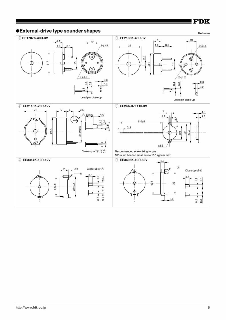
C EE1707K-40R-3V D EE2108K-40R-3V
G EE3314K-10R-12V
E EE2115K-28R-12V
H EE3406K-10R-60V
F EE24K-37F110-3V
Unit=mm
Recommended sclew fixing torqueM2 round headed small screw: 2.0 kg fcm max.
6.8
6.5
10
2-φ3.5
2-φ1.0
1.2φ1
7
10
0.4
0.8
Lead pin close-up
0.3
0.2
22
2.5
100.
4
0.8
φ21
7
1.2 6.5
10
2-φ3.5
2-φ1.2
0.3
0.2
Lead pin close-up
21.0
±0.5
21
24.5
9 6 3.5
3.56±0.5
1.2
2.0
3.5
0.2
0.6
A
Close-up of A
110±5
5±2
φ2.2
7
2.2
2.7
φ24
29 34.4
4.5
1.5
φ33.
5
35±0
.5
14 3.5
3.5
1.2
2.0
0.2
0.6
A
Close-up of A A
3.4
3.4
35
1.2
1.8
0.2
0.6
6.3
φ34
Close-up of A
External-drive type sounder shapes
6http://www.fdk.co.jp
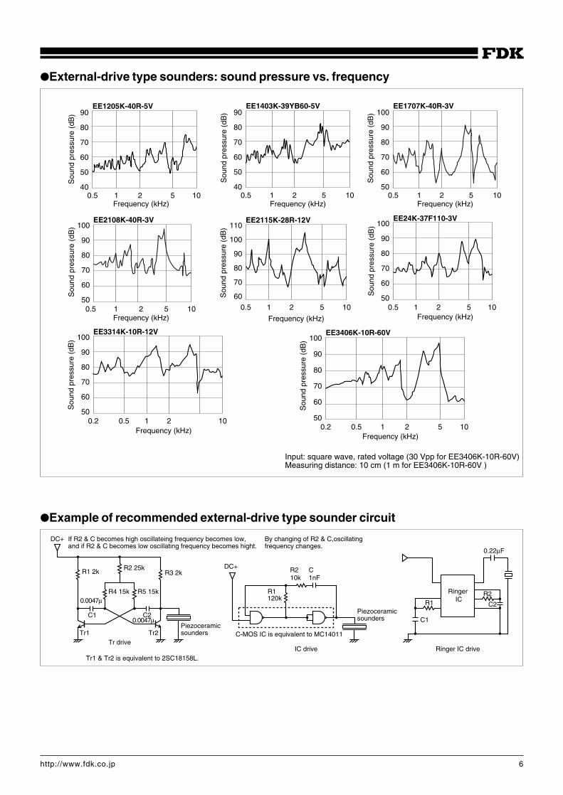
External-drive type sounders: sound pressure vs. frequency
1 20.5 105
110
100
90
80
70
60
EE2115K-28R-12V
1 20.5 105
100
90
80
70
60
50
EE24K-37F110-3V
1 20.5 105
90
80
70
60
50
40
EE1403K-39YB60-5V
Sou
nd p
ress
ure
(dB
)
Frequency (kHz)
1 20.5 105
100
90
80
70
60
50
EE2108K-40R-3V
Frequency (kHz)
Sou
nd p
ress
ure
(dB
)
1 20.5 105
100
90
80
70
60
50
EE1707K-40R-3V
Frequency (kHz)
Sou
nd p
ress
ure
(dB
)
Frequency (kHz)
Sou
nd p
ress
ure
(dB
)
Frequency (kHz)
Sou
nd p
ress
ure
(dB
)
0.5 10.2 102
100
90
80
70
60
50
EE3314K-10R-12V
Frequency (kHz)
Sou
nd p
ress
ure
(dB
)
0.5 10.2 102 5
100
90
80
70
60
50
EE3406K-10R-60V
Frequency (kHz)
Sou
nd p
ress
ure
(dB
)
1 20.5 105
90
80
70
60
50
40
EE1205K-40R-5V
Frequency (kHz)
Sou
nd p
ress
ure
(dB
)
Example of recommended external-drive type sounder circuit
Ringer IC driveIC driveTr drive
Ringer ICR1
R2
C1
C2
0.22µF
R1 2k
R4 15k R5 15k
R2 25k
C2C1
R3 2k
Tr1 Tr2
DC+
DC+
R2 C10k 1nF
R1120k
C-MOS IC is equivalent to MC14011Piezoceramicsounders
Piezoceramicsounders
0.0047µ
0.0047µ
If R2 & C becomes high oscillateing frequency becomes low,and if R2 & C becomes low oscillating frequency becomes hight.
By changing of R2 & C,oscillating frequency changes.
Tr1 & Tr2 is equivalent to 2SC18158L.
Input: square wave, rated voltage (30 Vpp for EE3406K-10R-60V)Measuring distance: 10 cm (1 m for EE3406K-10R-60V )
7http://www.fdk.co.jp
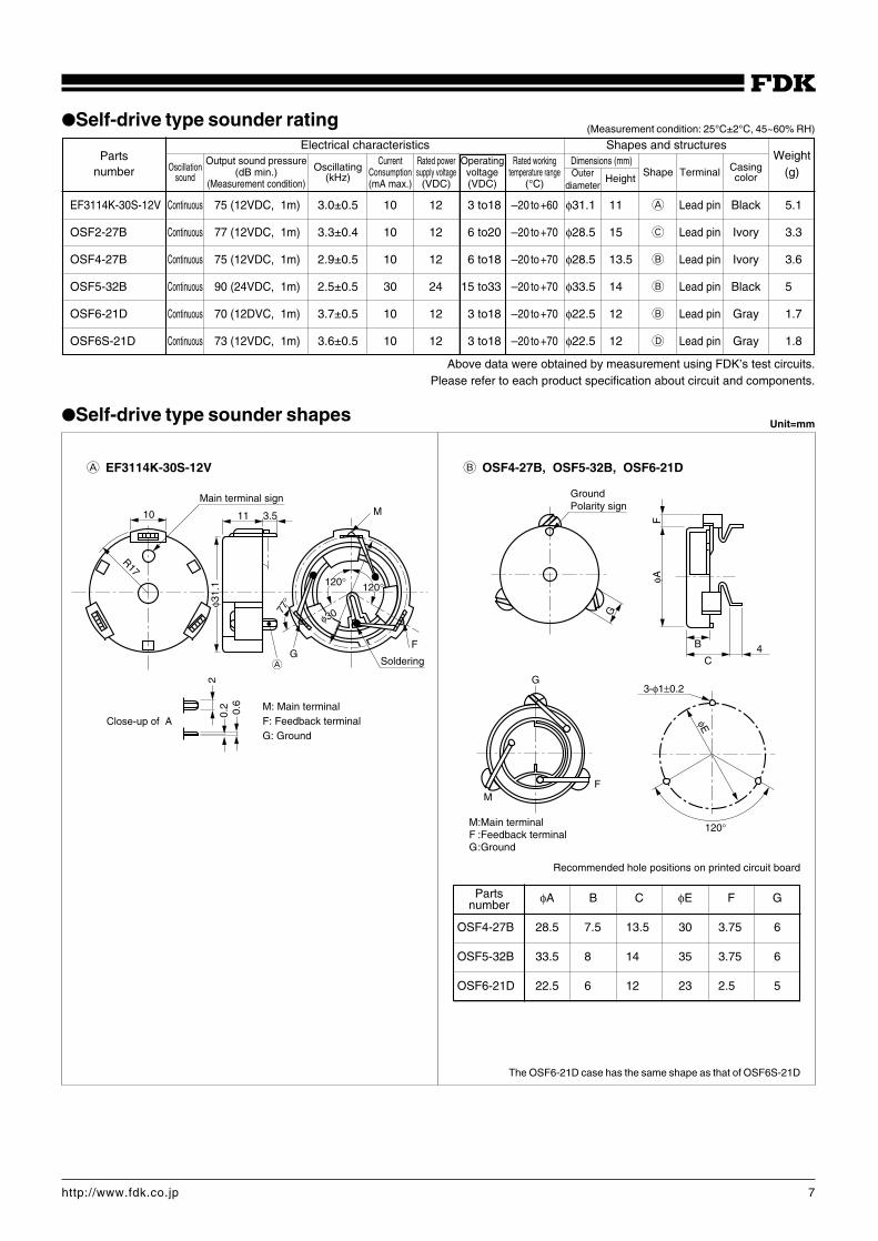
Self-drive type sounder rating
Partsnumber
Electrical characteristics Shapes and structuresWeight
(g)OscillationOutput sound pressure
OscillatingCurrent Rated power Operating Rated working Dimensions (mm)
Casing(dB min.) Consumption supply voltage voltage temperature rangeHeight
Shape Terminalsound(Measurement condition)
(kHz)(mA max.) (VDC) (VDC) (°C)
color
Above data were obtained by measurement using FDK’s test circuits.Please refer to each product specification about circuit and components.
Self-drive type sounder shapes
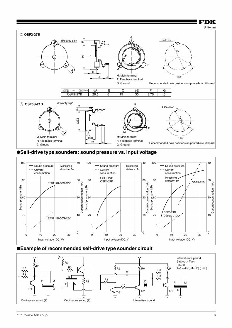
B OSF4-27B, OSF5-32B, OSF6-21DA EF3114K-30S-12V
M: Main terminalF: Feedback terminalG: Ground
φA B C φE F G
OSF4-27B 28.5 7.5 13.5 30 3.75 6
OSF5-32B 33.5 8 14 35 3.75 6
OSF6-21D 22.5 6 12 23 2.5 5
Recommended hole positions on printed circuit board
The OSF6-21D case has the same shape as that of OSF6S-21D
(Measurement condition: 25°C±2°C, 45~60% RH)
Unit=mm
10
R17
Main terminal sign
11 3.5
φ31.
1
AG
77°
Soldering
F
120°120°
φ30
20.
2 0.6
Close-up of A
M
GroundPolarity sign
G
FφA
B
C4
3-φ1±0.2
φE
120°
G
FM
Outerdiameter
M:Main terminalF :Feedback terminalG:Ground
Partsnumber
EF3114K-30S-12V Continuous 75 (12VDC, 1m) 3.0±0.5 10 12 3 to18 –20 to+60 φ31.1 11 A Lead pin Black 5.1
OSF2-27B Continuous 77 (12VDC, 1m) 3.3±0.4 10 12 6 to20 –20 to+70 φ28.5 15 C Lead pin Ivory 3.3
OSF4-27B Continuous 75 (12VDC, 1m) 2.9±0.5 10 12 6 to18 –20 to+70 φ28.5 13.5 B Lead pin Ivory 3.6
OSF5-32B Continuous 90 (24VDC, 1m) 2.5±0.5 30 24 15 to33 –20 to+70 φ33.5 14 B Lead pin Black 5
OSF6-21D Continuous 70 (12DVC, 1m) 3.7±0.5 10 12 3 to18 –20 to+70 φ22.5 12 B Lead pin Gray 1.7
OSF6S-21D Continuous 73 (12VDC, 1m) 3.6±0.5 10 12 3 to18 –20 to+70 φ22.5 12 D Lead pin Gray 1.8
8http://www.fdk.co.jp
C OSF2-27B
D OSF6S-21D
φA B C φE F GOSF2-27B 28.5 6 15 30 3.75 6
DimensionsParts No.
Self-drive type sounders: sound pressure vs. input voltage
70
80
90 30
100
0
10
20
40
100 20 30
Sou
nd p
ress
ure
(dB
)
Cur
rent
con
sum
ptio
n (m
A)
Input voltage (DC. V)
70
80
90 30
100
0
10
20
40
100 20 30
Sou
nd p
ress
ure
(dB
)
Cur
rent
con
sum
ptio
n (m
A)
Input voltage (DC. V)
EF3114K-30S-12V
EF3114K-30S-12V
OSF5-32B
OSF6-21DOSF6S-21D
Sound pressureCurrent consumption
Measuring distance: 1m
70
80
90 30
100
0
10
20
40
100 20 30
Sou
nd p
ress
ure
(dB
)
Cur
rent
con
sum
ptio
n (m
A)
Input voltage (DC. V)
Measuring distance: 1m
OSF2-27BOSF4-27B
Sound pressureCurrent consumption
Sound pressureCurrent consumption
Measuring distance: 1m
Example of recommended self-drive type sounder circuit
R2
R3
Tr1
F M
G
R1R2
R4
R5 R6
M
G
FR7
C
Tr3 Tr2
D
R2
R3
R1
Tr1
R3Tr
R1
G
F M
Continuous sound (1) Continuous sound (2) Intermittent sound
Intermittence period Setting of Tsec. R5=R6T=1.4×C×(R4+R5) (Sec.)
Unit=mm
+Polarity sign
G
φAF
B
C 4
φE
3-φ1±0.2
F
M
G
120°
6
23±0.3
3-φ0.9±0.1
FM
G+Polarity sign
2.5
φ22.
5
6
(12)
21 4120°
M: Main terminalF: Feedback terminalG: Ground
M: Main terminalF: Feedback terminalG: Ground
M: Main terminalF: Feedback terminalG: Ground
Recommended hole positions on printed circuit board
Recommended hole positions on printed circuit board
9http://www.fdk.co.jp
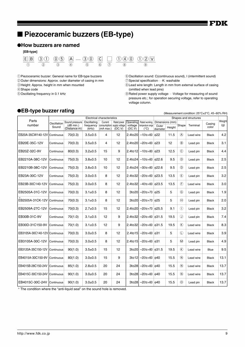
Piezoceramic buzzers (EB-type)How buzzers are named
[EB-type]
‰ı eq pt Å ep Ç Ç qrp qw◊q w e r t y u i o
qPiezoceramic buzzer: General name for EB-type buzzerswOuter dimensions: Approx. outer diameter of casing in mmeHeight: Approx. height in mm when mountedrShape codetOscillating frequency in 0.1 kHz
yOscillation sound: C(continuous sound), I (intermittent sound)uSpecial specification· · ·K: washableiLead wire length: Length in mm from external surface of casing
(omitted when lead pins)oRated power supply voltage· · ·Voltage for measuring of sound
pressure etc.; for operation securing voltage, refer to operating voltage column.
EB-type buzzer rating
Partsnumber
Weight(g)
Electrical characteristics Shapes and structures
Oscillation Sound pressure Oscillating Current Rated power Operating Rated working Dimensions (mm) Casing(dB min.) frequency consumption supply voltage voltage temperature range Shape TerminalSound (Distance:m) (kHz) (mA max.) (DC.V) (DC.V) (°C) Height color
F
(Measurement condition: 25°C±2°C, 45~60% RH)
Outerdiameter
F The condition where the “anti-liquid seal” on the sound hole is removed.
EB20A-35CW140-12V Continuous 70(0.3) 3.5±0.5 4 12 2.4to20 –10 to+60 φ22 11.5 A Lead wire Black 4.2
EB20E-35C-12V Continuous 70(0.3) 3.5±0.5 4 12 2.4to20 –20 to+60 φ23 12 B Lead pin Black 3.1
EB20Z-32C-9V Continuous 80(0.3) 3.2±0.5 15 9 2.4to12 –10 to+80 φ23 12.5 C Lead pin Black 4.4
EB2210A-38C-12V Continuous 75(0.3) 3.8±0.5 10 12 2.4to24 –10 to+60 φ22.6 9.5 D Lead pin Black 2.5
EB2210B-38C-12V Continuous 75(0.3) 3.8±0.5 10 12 2.4to24 –30 to+80 φ22.6 9.5 D Lead pin Black 2.5
EB23A-30C-12V Continuous 75(0.3) 3.0±0.5 8 12 2.4to32 –20 to+60 φ23.5 13.5 E Lead pin Black 3.2
EB23B-30C140-12V Continuous 75(0.3) 3.0±0.5 8 12 2.4to32 –40 to+60 φ23.5 13.5 F Lead wire Black 3.0
EB2505A-31C-12V Continuous 70(0.3) 3.1±0.5 8 12 3to20 –20 to+70 φ25 5 G Lead pin Black 1.9
EB2505A-31CK-12V Continuous 70(0.3) 3.1±0.5 8 12 3to20 –20 to+70 φ25 5 H Lead pin Black 2.0
EB2509A-27C-12V Continuous 70(0.3) 2.7±0.5 15 12 2.4to20 –20 to+70 φ25.5 9.1 I Lead pin Black 3.2
EB30B-31C-9V Continuous 70(1.0) 3.1±0.5 12 9 2.4to32 –20 to+60 φ31.5 19.5 J Lead pin Black 7.4
EB30D-31C150-9V Continuous 70(1.0) 3.1±0.5 12 9 2.4to32 –20 to+60 φ31.5 19.5 K Lead wire Black 8.3
EB3105A-30C140-12V Continuous 70(0.3) 3.0±0.5 8 12 2.4to15 –20 to+60 φ31 5 L Lead wire Black 3.9
EB3105A-30C-12V Continuous 70(0.3) 3.0±0.5 8 12 2.4to15 –20 to+60 φ31 5 M Lead pin Black 4.9
EB3120A-35C150-12V Continuous 90(1.0) 3.5±0.5 15 12 3to20 –20 to+80 φ31.5 19.5 K Lead wire Blue 9.5
EB4015A-30C150-9V Continuous 80(1.0) 3.0±0.5 15 9 3to12 –20 to+60 φ40 15.5 N Lead wire Black 13.1
EB4015B-28C150-24V Continuous 85(1.0) 2.8±0.5 20 24 3to28 –20 to+60 φ40 15.5 N Lead wire Black 13.7
EB4015C-30C150-24V Continuous 90(1.0) 3.0±0.5 20 24 3to28 –20 to+60 φ40 15.5 N Lead wire Black 13.7
EB4015C-30C-24V Continuous 90(1.0) 3.0±0.5 20 24 3to28 –20 to+60 φ40 15.5 O Lead pin Black 13.7
10http://www.fdk.co.jp
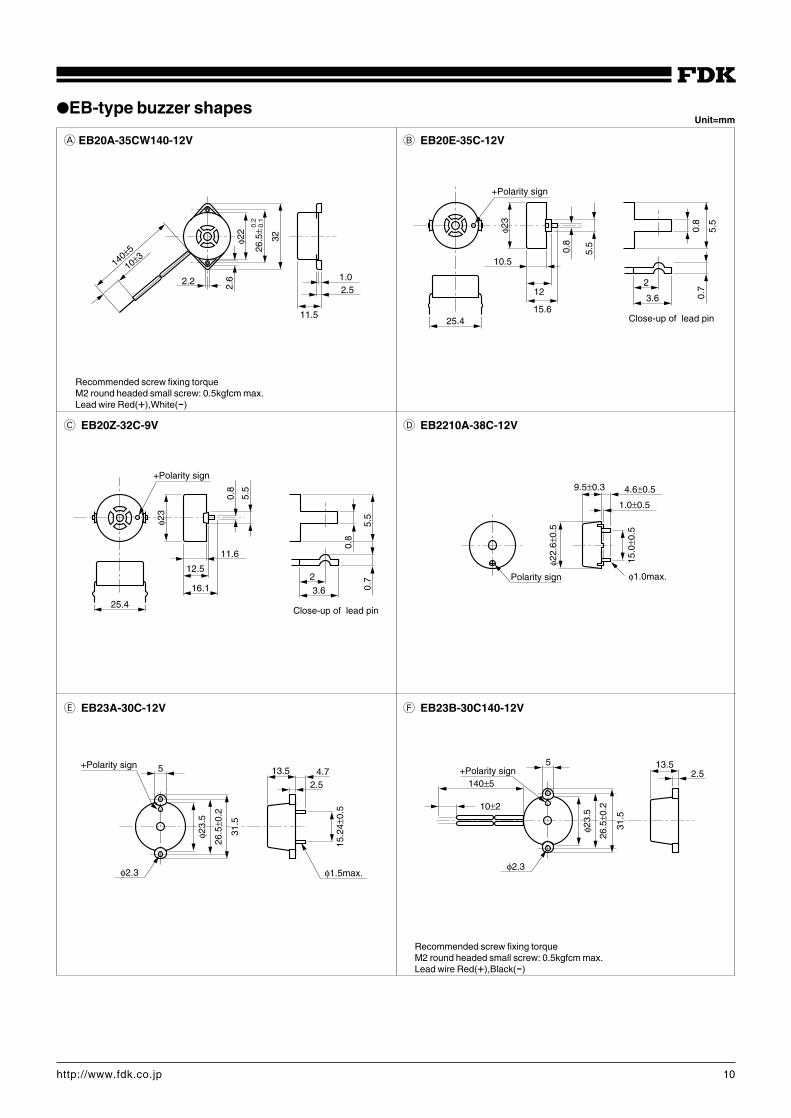
EB-type buzzer shapes
A EB20A-35CW140-12V B EB20E-35C-12V
C EB20Z-32C-9V
E EB23A-30C-12V
D EB2210A-38C-12V
F EB23B-30C140-12V
Recommended screw fixing torqueM2 round headed small screw: 0.5kgfcm max.Lead wire Red(+),White(-)
Recommended screw fixing torqueM2 round headed small screw: 0.5kgfcm max.Lead wire Red(+),Black(-)
Unit=mm
140±5
φ22
26.5
±
32
11.5
2.51.02.2 2.
6
10±30.
20.
1
15.6
12
10.5
φ23
25.4
0.8
5.5
+Polarity sign
5.5
0.8
0.7
2
3.6
Close-up of lead pin
+Polarity sign
φ23
11.6
12.5
16.1
0.8
5.5
3.6
2
0.7
5.5
25.4
0.8
Close-up of lead pin
Polarity sign
φ22.
6±0.
5
9.5±0.3 4.6±0.5
1.0±0.5
15.0
±0.5
φ1.0max.
+Polarity sign 5
φ23.
5
26.5
±0.2
31.5
φ2.3 φ1.5max.
13.5 4.72.5
15.2
4±0.
5
+Polarity sign
10±2
140±5
5
φ2.3
2.513.5
φ23.
5
26.5
±0.2
31.5
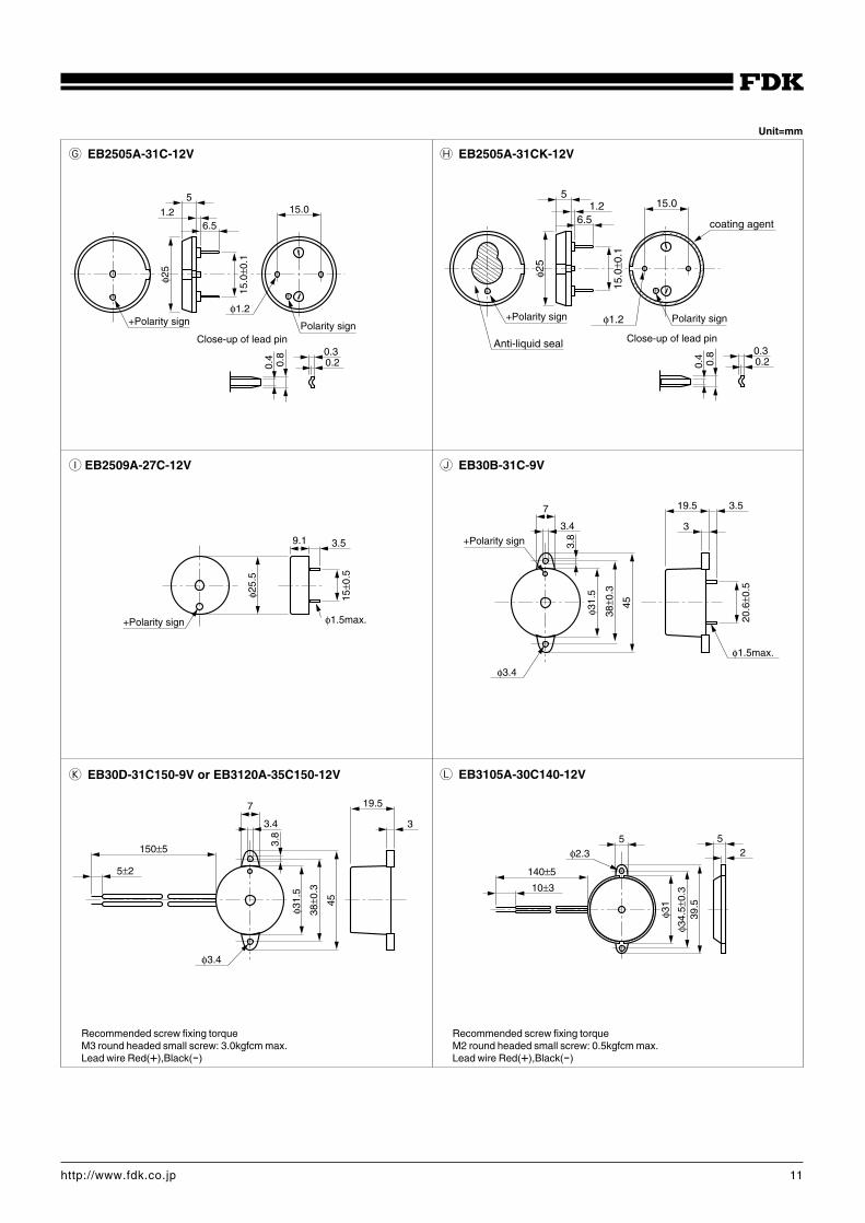
11http://www.fdk.co.jp
I EB2509A-27C-12V J EB30B-31C-9V
K EB30D-31C150-9V or EB3120A-35C150-12V L EB3105A-30C140-12V
+Polarity sign
φ25.
5
9.1 3.5
15±0
.5
φ1.5max.
φ3.4
+Polarity sign
19.5 3.5
3
φ1.5max.
20.6
±0.5
7
3.4
3.8
φ31.
5
38±0
.3
45
140±5
10±3
φ2.35 5
φ31
φ34.
5±0.
339
.5
2
5±2
150±5
7
3.4
3.8
φ31.
5
38±0
.3
45
φ3.4
19.5
3
Unit=mm
Recommended screw fixing torqueM3 round headed small screw: 3.0kgfcm max.Lead wire Red(+),Black(-)
G EB2505A-31C-12V H EB2505A-31CK-12V
5
+Polarity sign
1.26.5
φ25
15.0
±0.1
15.0
Polarity sign
φ1.2
0.4
0.8 0.3
0.2
Close-up of lead pin
515.0
Anti-liquid seal
+Polarity sign
1.26.5
φ25
15.0
±0.1
coating agent
φ1.2 Polarity sign
0.4
0.8 0.3
0.2
Close-up of lead pin
Recommended screw fixing torqueM2 round headed small screw: 0.5kgfcm max.Lead wire Red(+),Black(-)
12http://www.fdk.co.jp
N EB4015A or EB4015B or EB4015CM EB3105A-30C-12V
O EB4015C
Recommended screw fixing torqueM3 round headed small screw: 3.0kgfcm max.Lead wire Red(+),Black(-)
16.5φ3.5
φ40
50 60
3.5
5
5±215
0±5
4.515.5
5
1.26.5
φ31
17.5
φ2.0
φ4.517.5
+Polarity sign0.
40.
8 0.30.2
Close-up of lead pin
φ3.5
16.5
φ40
50 60
5
3.5 3.5
30
φ1.5MAX.
15.54.5
Slot indicates+pole
EB-type buzzers: sound pressure vs. input voltage
70
80
90 30
100
00
10
20
40
100 20 30
Sou
nd p
ress
ure
(dB
)
Cur
rent
con
sum
ptio
n (m
A)
Input voltage (DC. V)
e
qEB20A-35CW140-12VwEB20E-35C-12VeEB20Z-32C-9V
e
qw
qw
Sound pressureCurrebt consummption
Measuring distance: 0.3 m
i
i
r
r
ty
u
u
70
80
90 30
100
00
10
20
40
100 20 30
Sou
nd p
ress
ure
(dB
)
Cur
rent
con
sum
ptio
n (m
A)
Input voltage (DC. V)
ty
rEB2210A-38C-12VtEB23A-30C-12ViEB2505A-31C-12V, EB2505A-31CK-12V
yEB23B-30C140-12VuEB2509A-27C-12V
Sound pressureCurrent consumption
Measuring distance: 0.3m
Input voltage (DC. V)
!3
!1!2
oEB30B-31C-9V!0EB30D-31C150-9V!1EB3105A-30C140-12V
!2EB3105A-30C-12V!3EB3120A-35C150-12V
!1!2
!3
o!0
Sound pressureCurrent consumption
Measuring distance: 1m
70
80
90 30
100
00
10
20
40
100 20 30
Sou
nd p
ress
ure
(dB
)
Cur
rent
con
sum
ptio
n (m
A)
!4EB4015A!5EB4015B!6EB4015C
!6
!6
!4
!5Continuous
!5Intermittent
!4
Sound pressureCurrent consumptionMeasuring distance: 1m
80
90
100 30
110
00
10
20
40
100 20 30
Sou
nd p
ress
ure
(dB
)
Cur
rent
con
sum
ptio
n (m
A)
Input voltage (DC. V)
!5Continuous
!5Intermittent
13http://www.fdk.co.jp
14http://www.fdk.co.jp
EB2505A-31CK-12V washable typeWashing method
Buzzers of this model is wet-washable. For washing by other methods, please consult our engineers.
Resistance to solvents
EB2505A-31CK-12V buzzers have the following solvent-resistance characteristics. If you are planning to use solvents other than those listed
below, please consult our engineers.
Solvent-resistance test conditions
Dipped in solder pot (at 245±5°C for 8 sec.)
d
d
d
Immersed in solvent (for 30 minutes)
Dried (at 60°C for 30 minutes)
Standard reliability test (refer to P.19)
Test results
Solvent Result
Pure water K
Isopropyl alcohol (IPA) K
Toluene K
Isopropyl alcohol + toluene (1:1) K
Chlorosen K
Methanol ×Methylenechloride × K : Satisfactory
Trichloroethylene × × : Unsatisfactory
After washing, remove the “anti-liquid seal” before reuse.
15http://www.fdk.co.jp
Piezoceramic buzzers (U-type)Information on product naming
[U-type]
Ë w t p Â Î Î Ó q w ◊q w e r t y
U-type buzzer rating
Partsnumber
Electrical characteristics Shapes and structures
q Generic symbol for U-type piezoceramic buzzers r Oscillation sounds: R (continuous sounds), D1 (shortw Shape number intermittent sounds), D2 (long intermittent sounds)e Dimensions: Outer diameter of diaphragm (mm) t Symbol indicating the presence of a horn
y Rated power supply voltage:Voltage for measuring of sound pressure etc.; for operation securing voltage,refer to operating voltage column.
OscillationSound pressure Oscillating Operating Dimensions (mm)
Casing(dB min.) frequency voltage
HeightShape Terminal
sound(Distance:m) (kHz) (DC.V)
color
Weight(g)
U-type buzzer shapes
Intermitting period: 10 Hz±30% (short intermittent)2 Hz±30% (long intermittent)
FHeat resistance of U2 will be up to +85°C
Abbre. name Shape Input voltage characteristics
U4
1 2
(Measurement condition: 25°C±2°C, 45~60% RH)
Continuous
16.517.7 5
9
φ0.8
φ23±
0.5
15±0
.3
+Polarity sign
30
40
50
60
70
80
0
2
4
6
8
10
4 6 8 10 12 14 16
Sou
nd p
ress
ure
(dB
/1m
)
Cur
rent
con
sum
ptio
n (
mA
)
Input voltage (DC. V)
Sound pressureCurrent consumption
T
Outerdiameter
Solderedterminal
Unit = mm
Rated powersupply
voltage(DC.V)
Currentconsump-
tion(mA max)
Rated workingtemperature
range(°C)
U4B-21RM-1 72(1.0) 2.85±0.4 10 13 5 to15 –20 to + 70 φ23 18 T Black 4
16http://www.fdk.co.jp
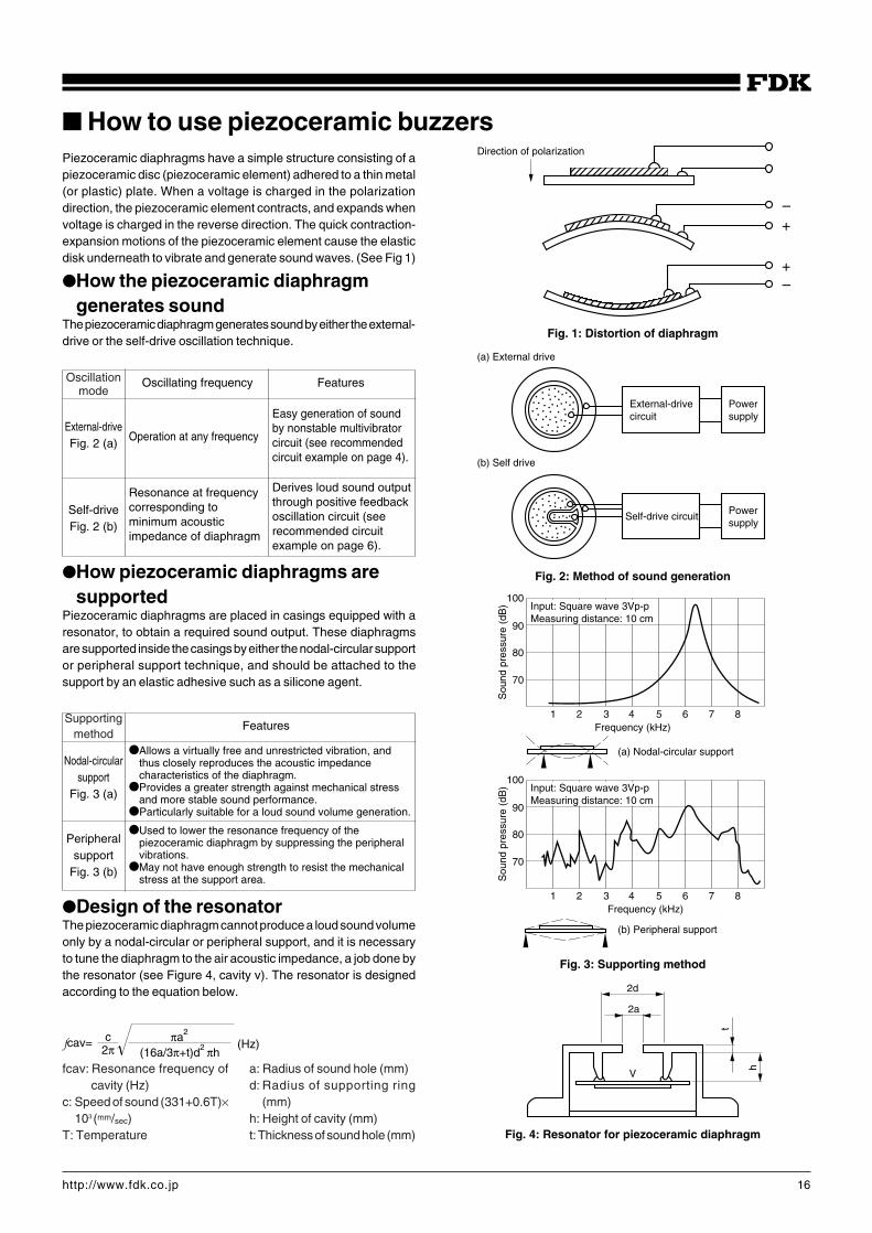
How to use piezoceramic buzzersPiezoceramic diaphragms have a simple structure consisting of apiezoceramic disc (piezoceramic element) adhered to a thin metal(or plastic) plate. When a voltage is charged in the polarizationdirection, the piezoceramic element contracts, and expands whenvoltage is charged in the reverse direction. The quick contraction-expansion motions of the piezoceramic element cause the elasticdisk underneath to vibrate and generate sound waves. (See Fig 1)
How the piezoceramic diaphragmgenerates sound
The piezoceramic diaphragm generates sound by either the external-drive or the self-drive oscillation technique.
How piezoceramic diaphragms aresupported
Piezoceramic diaphragms are placed in casings equipped with aresonator, to obtain a required sound output. These diaphragmsare supported inside the casings by either the nodal-circular supportor peripheral support technique, and should be attached to thesupport by an elastic adhesive such as a silicone agent.
Design of the resonatorThe piezoceramic diaphragm cannot produce a loud sound volumeonly by a nodal-circular or peripheral support, and it is necessaryto tune the diaphragm to the air acoustic impedance, a job done bythe resonator (see Figure 4, cavity v). The resonator is designedaccording to the equation below.
Oscillating frequency Features
External-driveFig. 2 (a)
Self-driveFig. 2 (b)
Operation at any frequency
Resonance at frequencycorresponding tominimum acousticimpedance of diaphragm
Easy generation of soundby nonstable multivibratorcircuit (see recommendedcircuit example on page 4).
Derives loud sound outputthrough positive feedbackoscillation circuit (seerecommended circuitexample on page 6).
Features
Nodal-circularsupport
Fig. 3 (a)
Peripheralsupport
Fig. 3 (b)
Allows a virtually free and unrestricted vibration, andthus closely reproduces the acoustic impedancecharacteristics of the diaphragm.
Provides a greater strength against mechanical stressand more stable sound performance.
Particularly suitable for a loud sound volume generation.
Used to lower the resonance frequency of thepiezoceramic diaphragm by suppressing the peripheralvibrations.
May not have enough strength to resist the mechanicalstress at the support area.
1 2 3 4 5 6 7 8
100
90
80
70
Sou
nd p
ress
ure
(dB
) Input: Square wave 3Vp-pMeasuring distance: 10 cm
(a) Nodal-circular support
1 2 3 4 5 6 7 8
100
90
80
70
Frequency (kHz)
Sou
nd p
ress
ure
(dB
)
Frequency (kHz)
Input: Square wave 3Vp-pMeasuring distance: 10 cm
(b) Peripheral support
Fig. 3: Supporting method
Fig. 4: Resonator for piezoceramic diaphragm
2d
2a
h
t
V
External-drive circuit
Power supply
Self-drive circuit Power supply
Fig. 2: Method of sound generation
(a) External drive
(b) Self drive
Direction of polarization
Fig. 1: Distortion of diaphragm
+
+
–
–
(16a/3π+t)d2 πhπa2
(Hz)2πcfcav=
Oscillationmode
Supportingmethod
fcav: Resonance frequency ofcavity (Hz)
c: Speed of sound (331+0.6T)×103 (mm/sec)
T: Temperature
a: Radius of sound hole (mm)d: Radius of supporting ring
(mm)h: Height of cavity (mm)t: Thickness of sound hole (mm)
17http://www.fdk.co.jp
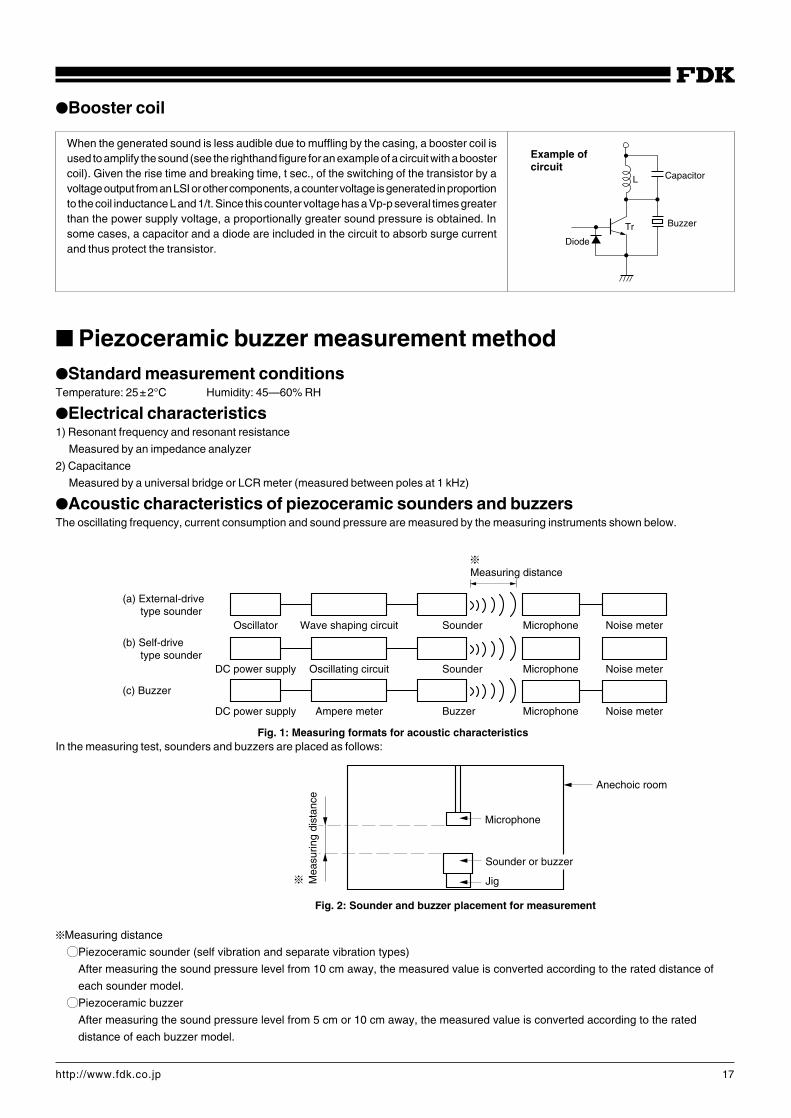
Booster coil
When the generated sound is less audible due to muffling by the casing, a booster coil isused to amplify the sound (see the righthand figure for an example of a circuit with a boostercoil). Given the rise time and breaking time, t sec., of the switching of the transistor by avoltage output from an LSI or other components, a counter voltage is generated in proportionto the coil inductance L and 1/t. Since this counter voltage has a Vp-p several times greaterthan the power supply voltage, a proportionally greater sound pressure is obtained. Insome cases, a capacitor and a diode are included in the circuit to absorb surge currentand thus protect the transistor.
Piezoceramic buzzer measurement methodStandard measurement conditionsTemperature: 25±2°C Humidity: 45—60% RH
Electrical characteristics1) Resonant frequency and resonant resistance
Measured by an impedance analyzer
2) Capacitance
Measured by a universal bridge or LCR meter (measured between poles at 1 kHz)
Acoustic characteristics of piezoceramic sounders and buzzersThe oscillating frequency, current consumption and sound pressure are measured by the measuring instruments shown below.
Oscillator Wave shaping circuit Sounder
Sounder
Microphone
Microphone
Microphone
Noise meter
Noise meter
Noise meter
Oscillating circuitDC power supply
DC power supply Ampere meter Buzzer
F
Measuring distance
(a) External-drive type sounder
(b) Self-drive type sounder
(c) Buzzer
Fig. 1: Measuring formats for acoustic characteristics
Microphone
Sounder or buzzer
Jig
Fig. 2: Sounder and buzzer placement for measurement
F Mea
surin
g di
stan
ce
Anechoic room
In the measuring test, sounders and buzzers are placed as follows:
FMeasuring distance
KPiezoceramic sounder (self vibration and separate vibration types)
After measuring the sound pressure level from 10 cm away, the measured value is converted according to the rated distance of
each sounder model.
KPiezoceramic buzzer
After measuring the sound pressure level from 5 cm or 10 cm away, the measured value is converted according to the rated
distance of each buzzer model.
Example ofcircuit
L Capacitor
Buzzer
Diode
Tr
18http://www.fdk.co.jp
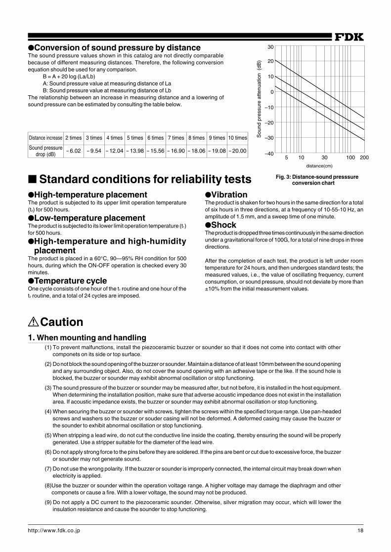
Conversion of sound pressure by distanceThe sound pressure values shown in this catalog are not directly comparablebecause of different measuring distances. Therefore, the following conversionequation should be used for any comparison.
B = A + 20 log (La/Lb)A: Sound pressure value at measuring distance of LaB: Sound pressure value at measuring distance of Lb
The relationship between an increase in measuring distance and a lowering ofsound pressure can be estimated by consulting the table below.
Distance increase 2 times 3 times 4 times 5 times 6 times 7 times 8 times 9 times 10 times
– 6.02 – 9.54 – 12.04 – 13.98 – 15.56 – 16.90 – 18.06 – 19.08 – 20.00
30
20
10
0
–10
–20
–30
–405 10 30 100 200
distance(cm)
Sou
nd p
ress
ure
atte
nuat
ion
(dB
)
Standard conditions for reliability testsHigh-temperature placementThe product is subjected to its upper limit operation temperature(t2) for 500 hours.
Low-temperature placementThe product is subjected to its lower limit operation temperature (t1)for 500 hours.
High-temperature and high-humidityplacement
The product is placed in a 60°C, 90—95% RH condition for 500hours, during which the ON-OFF operation is checked every 30minutes.
Temperature cycleOne cycle consists of one hour of the t1 routine and one hour of thet2 routine, and a total of 24 cycles are imposed.
VibrationThe product is shaken for two hours in the same direction for a totalof six hours in three directions, at a frequency of 10-55-10 Hz, anamplitude of 1.5 mm, and a sweep time of one minute.
ShockThe product is dropped three times continuously in the same directionunder a gravitational force of 100G, for a total of nine drops in threedirections.
After the completion of each test, the product is left under roomtemperature for 24 hours, and then undergoes standard tests; themeasured values, i.e., the value of oscillating frequency, currentconsumption, or sound pressure, should not deviate by more than±10% from the initial measurement values.
Caution1. When mounting and handling
(1) To prevent malfunctions, install the piezoceramic buzzer or sounder so that it does not come into contact with othercomponets on its side or top surface.
(2) Do not block the sound opening of the buzzer or sounder. Maintain a distance of at least 10mm between the sound openingand any surrounding object. Also, do not cover the sound opening with an adhesive tape or the like. If the sound hole isblocked, the buzzer or sounder may exhibit abnormal oscillation or stop functioning.
(3) The sound pressure of the buzzer or sounder may be measured after, but not before, it is installed in the host equipment.When determining the installation position, make sure that adverse acoustic impedance does not exist in the installationarea. If acoustic impedance exists, the buzzer or sounder may exhibit abnormal oscillation or stop functioning.
(4) When securing the buzzer or sounder with screws, tighten the screws within the specified torque range. Use pan-headedscrews and washers so the buzzer or souder casing will not be deformed. A deformed casing may cause the buzzer orthe sounder to exhibit abnormal oscillation or stop functioning.
(5) When stripping a lead wire, do not cut the conductive line inside the coating, thereby ensuring the sound will be properlygenerated. Use a stripper suitable for the diameter of the lead wire.
(6) Do not apply strong force to the pins before they are soldered. If the pins are bent or cut due to excessive force, the buzzeror sounder may not generate sound.
(7) Do not use the wrong polarity. If the buzzer or sounder is improperly connected, the internal circuit may break down whenelectricity is applied.
(8)Use the buzzer or sounder within the operation voltage range. A higher voltage may damage the diaphragm and othercomponets or cause a fire. With a lower voltage, the sound may not be produced.
(9) Do not apply a DC current to the piezoceramic sounder. Otherwise, silver migration may occur, which will lower theinsulation resistance and cause the sounder to stop functioning.
Sound pressuredrop (dB)
Fig. 3: Distance-sound presssureconversion chart
19http://www.fdk.co.jp
(10) Use a low-impedance (not more than 100 Ω) power supply for the buzzer; otherwise, the buzzer may exhibit abnormaloscillation or stop functioning.
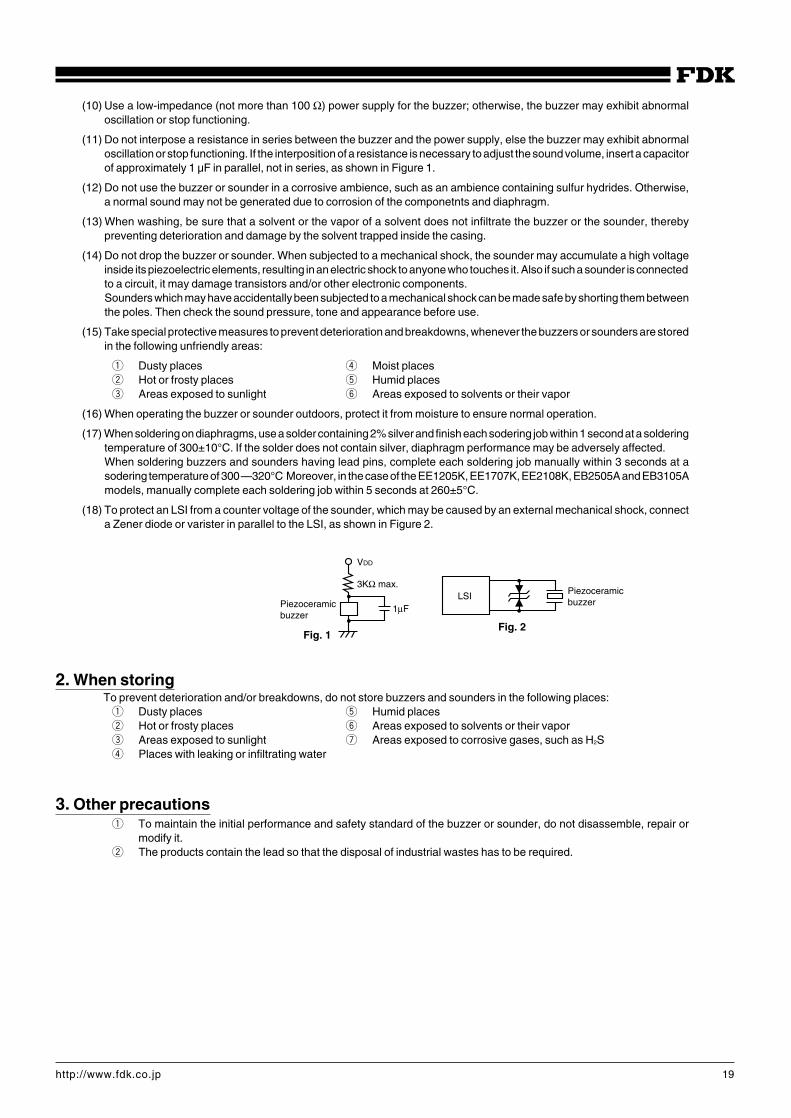
(11) Do not interpose a resistance in series between the buzzer and the power supply, else the buzzer may exhibit abnormaloscillation or stop functioning. If the interposition of a resistance is necessary to adjust the sound volume, insert a capacitorof approximately 1 µF in parallel, not in series, as shown in Figure 1.
(12) Do not use the buzzer or sounder in a corrosive ambience, such as an ambience containing sulfur hydrides. Otherwise,a normal sound may not be generated due to corrosion of the componetnts and diaphragm.
(13) When washing, be sure that a solvent or the vapor of a solvent does not infiltrate the buzzer or the sounder, therebypreventing deterioration and damage by the solvent trapped inside the casing.
(14) Do not drop the buzzer or sounder. When subjected to a mechanical shock, the sounder may accumulate a high voltageinside its piezoelectric elements, resulting in an electric shock to anyone who touches it. Also if such a sounder is connectedto a circuit, it may damage transistors and/or other electronic components.Sounders which may have accidentally been subjected to a mechanical shock can be made safe by shorting them betweenthe poles. Then check the sound pressure, tone and appearance before use.
(15) Take special protective measures to prevent deterioration and breakdowns, whenever the buzzers or sounders are storedin the following unfriendly areas:
q Dusty places r Moist placesw Hot or frosty places t Humid placese Areas exposed to sunlight y Areas exposed to solvents or their vapor
(16) When operating the buzzer or sounder outdoors, protect it from moisture to ensure normal operation.
(17) When soldering on diaphragms, use a solder containing 2% silver and finish each sodering job within 1 second at a solderingtemperature of 300±10°C. If the solder does not contain silver, diaphragm performance may be adversely affected.When soldering buzzers and sounders having lead pins, complete each soldering job manually within 3 seconds at asodering temperature of 300—320°C Moreover, in the case of the EE1205K, EE1707K, EE2108K, EB2505A and EB3105Amodels, manually complete each soldering job within 5 seconds at 260±5°C.
(18) To protect an LSI from a counter voltage of the sounder, which may be caused by an external mechanical shock, connecta Zener diode or varister in parallel to the LSI, as shown in Figure 2.
2. When storingTo prevent deterioration and/or breakdowns, do not store buzzers and sounders in the following places:q Dusty places t Humid placesw Hot or frosty places y Areas exposed to solvents or their vapore Areas exposed to sunlight u Areas exposed to corrosive gases, such as H2Sr Places with leaking or infiltrating water
3. Other precautionsq To maintain the initial performance and safety standard of the buzzer or sounder, do not disassemble, repair or
modify it.w The products contain the lead so that the disposal of industrial wastes has to be required.
Piezoceramicbuzzer
Fig. 1
VDD
3KΩ max.LSI
Fig. 2
Piezoceramicbuzzer
1µF
FDK Web Site
Electronics sales div.5-36-11, Shinbashi, Minato-ku, Tokyo 105-8677, Japan (Hamagomu Bldg.)TEL: (81)-3-5473-4662 FAX: (81)-3-3431-9436
U.S.A. FDK AMERICA, INC. CORPORATE OFFICE2270 North First Street, San Jose, California 95131-2022, U.S.A.TEL: (1)-408-432-8331 FAX: (1)-408-435-7478
FDK AMERICA, INC. BOSTON OFFICE411 Waverley Oaks Road, Suite 324, Waltham, Massachusetts 02452-8437, U.S.A.TEL: (1)-781-899-7700 FAX: (1)-781-899-7701
FDK AMERICA, INC. SAN DIEGO OFFICE 6540 Luck Blvd Suite C274 San Diego,California 92121-2766, U.S.A.TEL: (1)-858-558-8368 FAX: (1)-858-558-6005
Europe FDK ELECTRONICS GMBHHeerdter Lohweg 89, 40549 Düsseldorf, GermanyTEL: (49)-211-591574 FAX: (49)-211-593549
FDK ELECTRONICS UK LIMITEDSuite 4C Celect House 12A Fairbairn Road, Kirkton North Livingston EH54 6TS, Scotland, United KingdomTEL: (44)-1506-467981 FAX: (44)-1506-467982
Asia FDK HONG KONG LTD.SUITE 1601-1602, Tower 3, China Hong Kong City, 33 Canton Road, Tsim Sha Tsui Kowloon, Hong KongTEL: (852)-27999773 FAX: (852)-27554635
FDK SINGAPORE PTE., LTD.4, Leng Kee Road, #06-07/08 SiS Building, Singapore. 159088, Republic of SingaporeTEL: (65)-472-2328 FAX: (65)-472-5761
For improvement of its products, FDK reserves the right to change specificationswithout prior notice to customers.