PIERGIORGIO BERUTO ANTONIO ORZELLI
23
Public Document Canova Tech The Art of Silicon Sculpting PIERGIORGIO BERUTO ANTONIO ORZELLI IEEE 802.3 Plenary Meeting, San Diego (CA) 2018 802.3cg draft 2.0 PLCA (Clause 148) Overview July 9 th , 2018
Transcript of PIERGIORGIO BERUTO ANTONIO ORZELLI
Public Document
Canova TechThe Art of Silicon Sculpting
PIERGIORGIO BERUTO
ANTONIO ORZELLI
IEEE 802.3 Plenary Meeting, San Diego (CA) 2018802.3cg draft 2.0 PLCA (Clause 148) Overview
July 9th, 2018
Public Document
Introduction
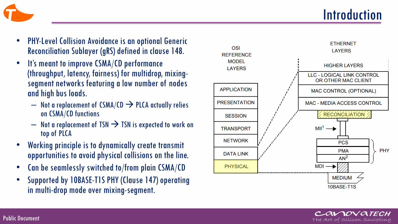
• PHY-Level Collision Avoidance is an optional Generic Reconciliation Sublayer (gRS) defined in clause 148.
• It’s meant to improve CSMA/CD performance (throughput, latency, fairness) for multidrop, mixing-segment networks featuring a low number of nodes and high bus loads.
– Not a replacement of CSMA/CD → PLCA actually relies on CSMA/CD functions
– Not a replacement of TSN → TSN is expected to work on top of PLCA
• Working principle is to dynamically create transmit opportunities to avoid physical collisions on the line.
• Can be seamlessly switched to/from plain CSMA/CD
• Supported by 10BASE-T1S PHY (Clause 147) operating in multi-drop mode over mixing-segment.
Public Document
PLCA in a nutshell
0
LINE
BEACON
COMMIT
DATA
0
SILENCE
0 1 … N 0 0 1 2 3 3
MIN PLCA cycle TO_TIMER (20 bits)
0 0 1 1 … N N 0…
MAX PLCA cycle →MAX latency
MAX Packet Size
0
4 … N 0 0
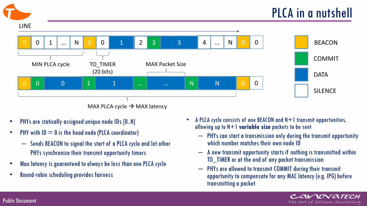
• PHYs are statically assigned unique node IDs [0..N]
• PHY with ID = 0 is the head node (PLCA coordinator)
– Sends BEACON to signal the start of a PLCA cycle and let other
PHYs synchronize their transmit opportunity timers
• Max latency is guaranteed to always be less than one PLCA cycle
• Round-robin scheduling provides fairness
• A PLCA cycle consists of one BEACON and N+1 transmit opportunities, allowing up to N+1 variable size packets to be sent
– PHYs can start a transmission only during the transmit opportunity which number matches their own node ID
– A new transmit opportunity starts if nothing is transmitted within TO_TIMER or at the end of any packet transmission
– PHYs are allowed to transmit COMMIT during their transmit opportunity to compensate for any MAC latency (e.g. IPG) before transmitting a packet
Public Document
PLCA model
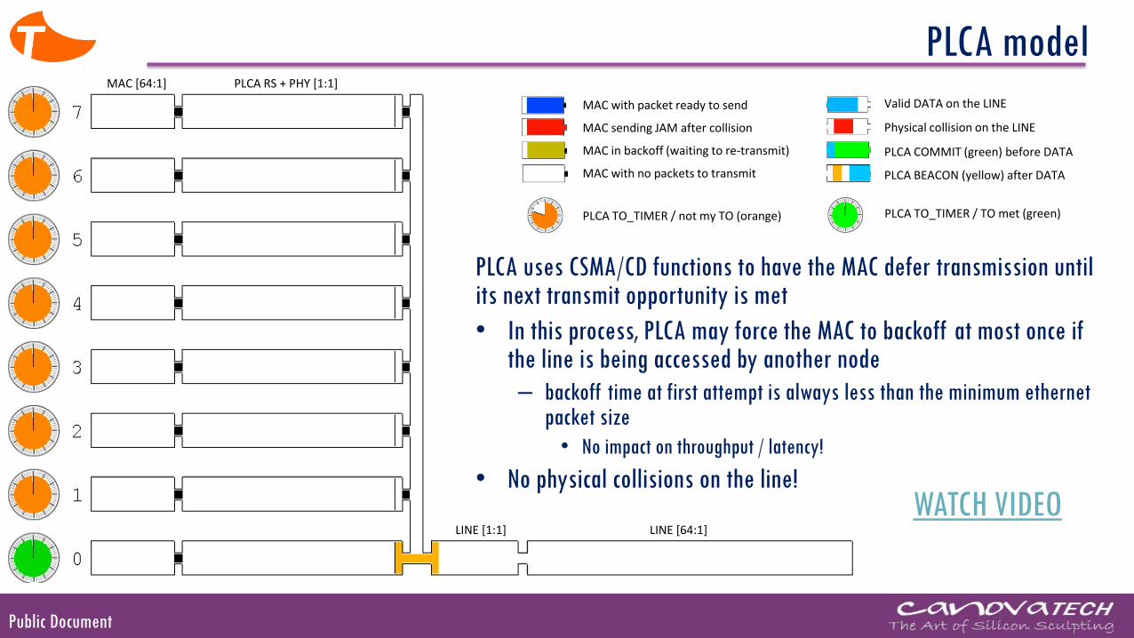
PLCA uses CSMA/CD functions to have the MAC defer transmission until its next transmit opportunity is met
• In this process, PLCA may force the MAC to backoff at most once if the line is being accessed by another node
– backoff time at first attempt is always less than the minimum ethernet packet size
• No impact on throughput / latency!
• No physical collisions on the line!
MAC [64:1] PLCA RS + PHY [1:1]
LINE [1:1] LINE [64:1]
MAC with packet ready to send
MAC sending JAM after collision
MAC in backoff (waiting to re-transmit)
Valid DATA on the LINE
Physical collision on the LINE
PLCA COMMIT (green) before DATA
PLCA BEACON (yellow) after DATAMAC with no packets to transmit
PLCA TO_TIMER / not my TO (orange) PLCA TO_TIMER / TO met (green)
WATCH VIDEO
Public Document
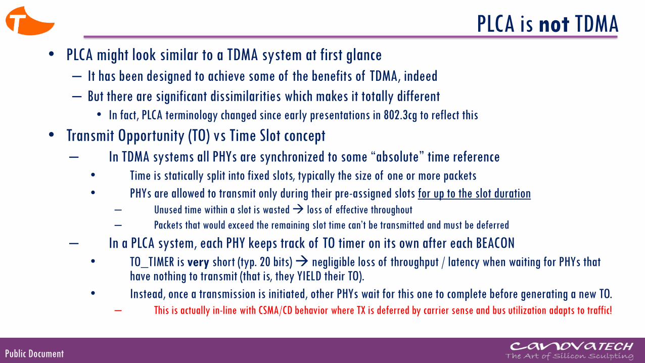
PLCA is not TDMA
• PLCA might look similar to a TDMA system at first glance
– It has been designed to achieve some of the benefits of TDMA, indeed
– But there are significant dissimilarities which makes it totally different
• In fact, PLCA terminology changed since early presentations in 802.3cg to reflect this
• Transmit Opportunity (TO) vs Time Slot concept
– In TDMA systems all PHYs are synchronized to some “absolute” time reference
• Time is statically split into fixed slots, typically the size of one or more packets
• PHYs are allowed to transmit only during their pre-assigned slots for up to the slot duration
– Unused time within a slot is wasted → loss of effective throughout
– Packets that would exceed the remaining slot time can’t be transmitted and must be deferred
– In a PLCA system, each PHY keeps track of TO timer on its own after each BEACON
• TO_TIMER is very short (typ. 20 bits) → negligible loss of throughput / latency when waiting for PHYs that have nothing to transmit (that is, they YIELD their TO).
• Instead, once a transmission is initiated, other PHYs wait for this one to complete before generating a new TO.
– This is actually in-line with CSMA/CD behavior where TX is deferred by carrier sense and bus utilization adapts to traffic!
Public Document
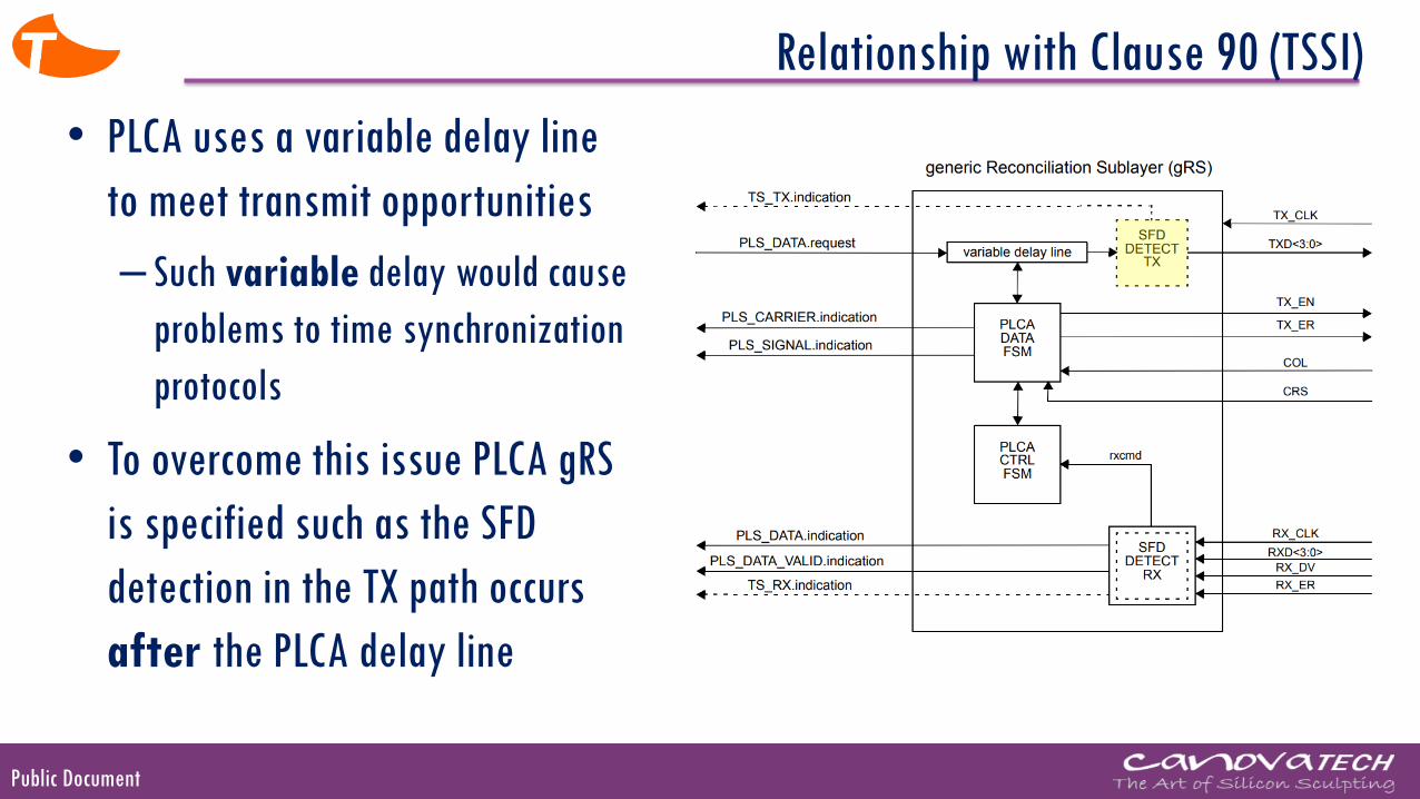
Relationship with Clause 90 (TSSI)
• PLCA uses a variable delay line
to meet transmit opportunities
– Such variable delay would cause
problems to time synchronization
protocols
• To overcome this issue PLCA gRS
is specified such as the SFD
detection in the TX path occurs
after the PLCA delay line

Public Document
How PLCA
Works
Public Document
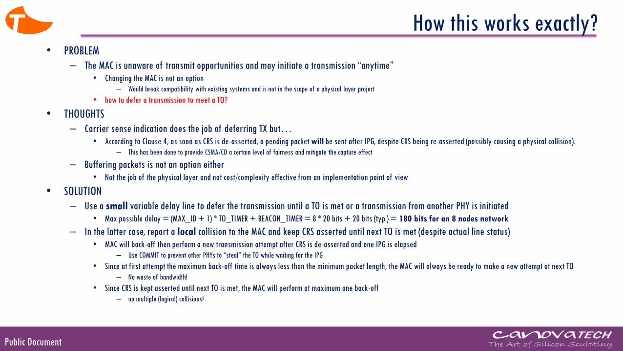
How this works exactly? • PROBLEM
– The MAC is unaware of transmit opportunities and may initiate a transmission “anytime”• Changing the MAC is not an option
– Would break compatibility with existing systems and is not in the scope of a physical layer project
• how to defer a transmission to meet a TO?
• THOUGHTS
– Carrier sense indication does the job of deferring TX but…• According to Clause 4, as soon as CRS is de-asserted, a pending packet will be sent after IPG, despite CRS being re-asserted (possibly causing a physical collision).
– This has been done to provide CSMA/CD a certain level of fairness and mitigate the capture effect
– Buffering packets is not an option either• Not the job of the physical layer and not cost/complexity effective from an implementation point of view
• SOLUTION
– Use a small variable delay line to defer the transmission until a TO is met or a transmission from another PHY is initiated• Max possible delay = (MAX_ID + 1) * TO_TIMER + BEACON_TIMER = 8 * 20 bits + 20 bits (typ.) = 180 bits for an 8 nodes network
– In the latter case, report a local collision to the MAC and keep CRS asserted until next TO is met (despite actual line status)• MAC will back-off then perform a new transmission attempt after CRS is de-asserted and one IPG is elapsed
– Use COMMIT to prevent other PHYs to “steal” the TO while waiting for the IPG
• Since at first attempt the maximum back-off time is always less than the minimum packet length, the MAC will always be ready to make a new attempt at next TO
– No waste of bandwidth!
• Since CRS is kept asserted until next TO is met, the MAC will perform at maximum one back-off
– no multiple (logical) collisions!
Public Document
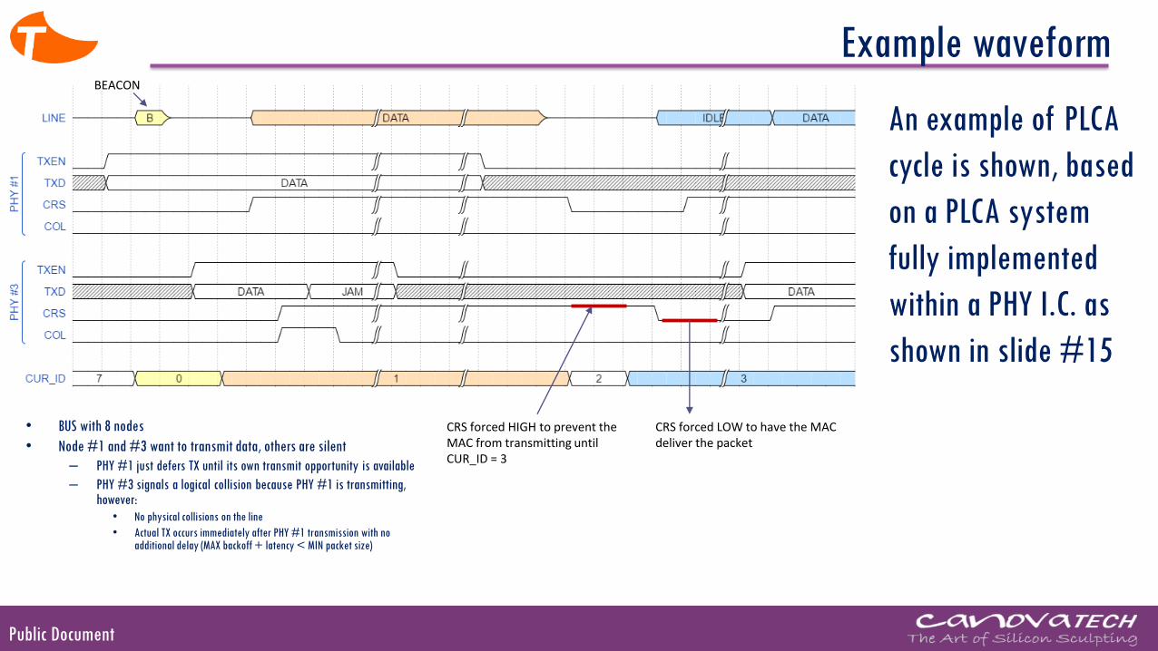
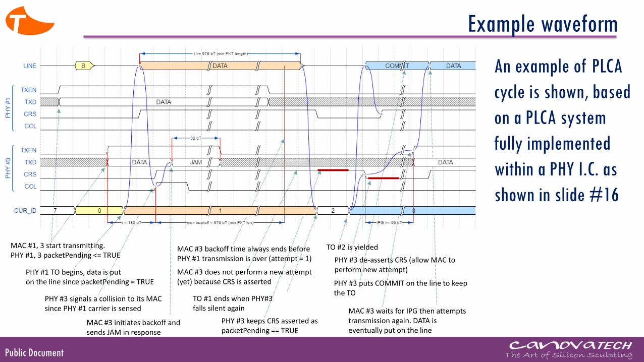
Example waveform
CRS forced HIGH to prevent the MAC from transmitting until CUR_ID = 3
CRS forced LOW to have the MAC deliver the packet
• BUS with 8 nodes
• Node #1 and #3 want to transmit data, others are silent
– PHY #1 just defers TX until its own transmit opportunity is available
– PHY #3 signals a logical collision because PHY #1 is transmitting, however:
• No physical collisions on the line
• Actual TX occurs immediately after PHY #1 transmission with no additional delay (MAX backoff + latency < MIN packet size)
BEACON
An example of PLCA
cycle is shown, based
on a PLCA system
fully implemented
within a PHY I.C. as
shown in slide #15
Public Document
Example waveform
MAC #1, 3 start transmitting.PHY #1, 3 packetPending <= TRUE
PHY #1 TO begins, data is puton the line since packetPending = TRUE
PHY #3 signals a collision to its MACsince PHY #1 carrier is sensed
MAC #3 initiates backoff andsends JAM in response
MAC #3 backoff time always ends before PHY #1 transmission is over (attempt = 1)
TO #1 ends when PHY#3falls silent again
TO #2 is yielded
PHY #3 de-asserts CRS (allow MAC to perform new attempt)
MAC #3 waits for IPG then attempts transmission again. DATA is eventually put on the line
PHY #3 keeps CRS asserted aspacketPending == TRUE
MAC #3 does not perform a new attempt(yet) because CRS is asserted PHY #3 puts COMMIT on the line to keep
the TO
An example of PLCA
cycle is shown, based
on a PLCA system
fully implemented
within a PHY I.C. as
shown in slide #16
Public Document
Performance
Simulations
Public Document
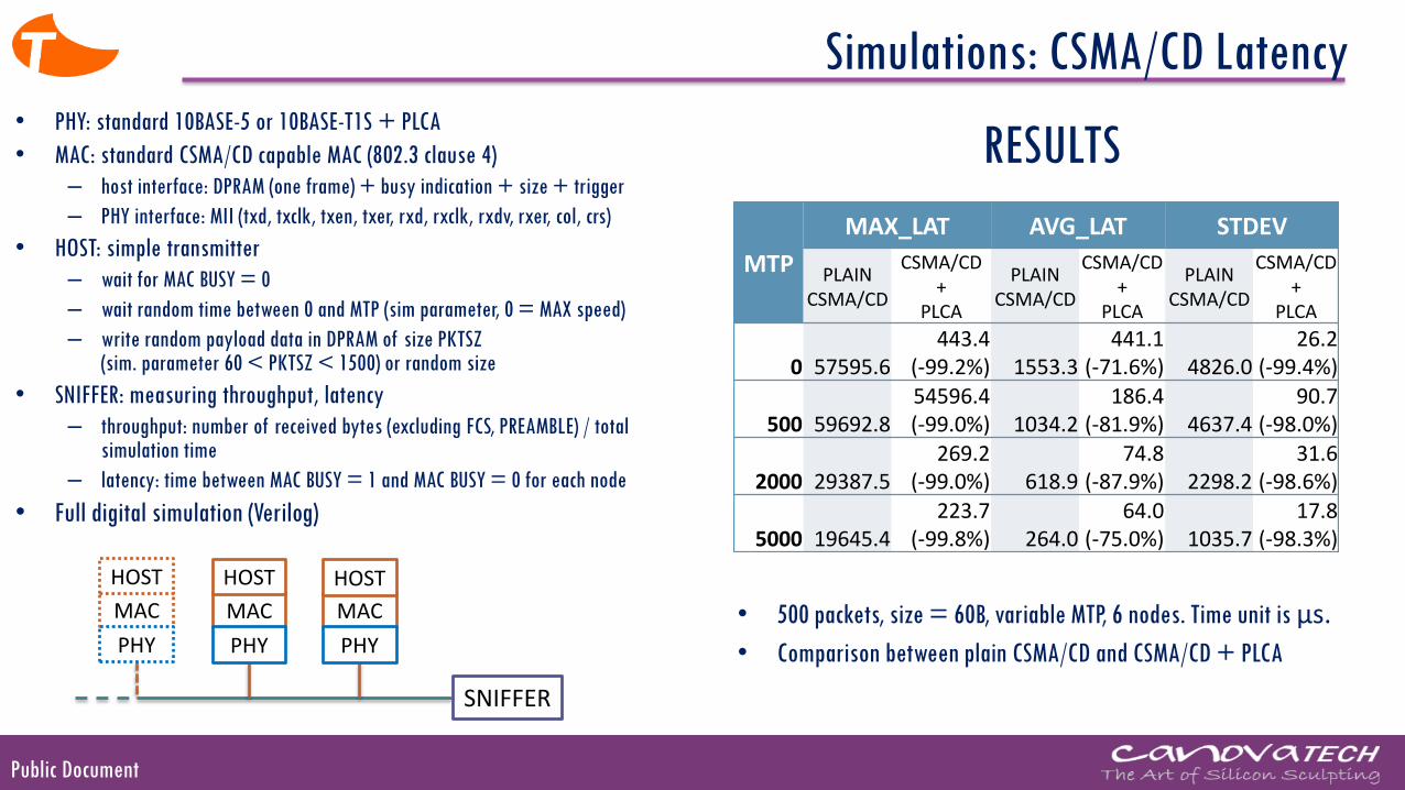
Simulations: CSMA/CD Latency• PHY: standard 10BASE-5 or 10BASE-T1S + PLCA
• MAC: standard CSMA/CD capable MAC (802.3 clause 4)
– host interface: DPRAM (one frame) + busy indication + size + trigger
– PHY interface: MII (txd, txclk, txen, txer, rxd, rxclk, rxdv, rxer, col, crs)
• HOST: simple transmitter
– wait for MAC BUSY = 0
– wait random time between 0 and MTP (sim parameter, 0 = MAX speed)
– write random payload data in DPRAM of size PKTSZ (sim. parameter 60 < PKTSZ < 1500) or random size
• SNIFFER: measuring throughput, latency
– throughput: number of received bytes (excluding FCS, PREAMBLE) / total simulation time
– latency: time between MAC BUSY = 1 and MAC BUSY = 0 for each node
• Full digital simulation (Verilog)
MAC MACMAC
SNIFFER
HOST HOSTHOST
PHY PHYPHY
MTP
MAX_LAT AVG_LAT STDEV
PLAIN CSMA/CD
CSMA/CD +
PLCA
PLAIN CSMA/CD
CSMA/CD +
PLCA
PLAIN CSMA/CD
CSMA/CD +
PLCA
0 57595.6443.4
(-99.2%) 1553.3441.1
(-71.6%) 4826.026.2
(-99.4%)
500 59692.854596.4(-99.0%) 1034.2
186.4(-81.9%) 4637.4
90.7(-98.0%)
2000 29387.5269.2
(-99.0%) 618.974.8
(-87.9%) 2298.231.6
(-98.6%)
5000 19645.4223.7
(-99.8%) 264.064.0
(-75.0%) 1035.717.8
(-98.3%)
• 500 packets, size = 60B, variable MTP, 6 nodes. Time unit is μs.
• Comparison between plain CSMA/CD and CSMA/CD + PLCA
RESULTS

Public Document
0.00
1.00
2.00
3.00
4.00
5.00
6.00
7.00
8.00
9.00
10.00
1 2 3 4 5 6
Mb
it/s
NUM PHYs
Bitrate, MTP = 5000
PROPOSAL
10base-T
Simulations: CSMA/CD Throughput
0.00
1.00
2.00
3.00
4.00
5.00
6.00
7.00
8.00
9.00
10.00
1 2 3 4 5 6
Mb
it/s
NUM PHYs
Bitrate, MTP = 0
PROPOSAL
10base-T
0.00
1.00
2.00
3.00
4.00
5.00
6.00
7.00
8.00
9.00
10.00
1 2 3 4 5 6
Mb
it/s
NUM PHYs
Bitrate, MTP = 500
PROPOSAL
10base-T
0.00
1.00
2.00
3.00
4.00
5.00
6.00
7.00
8.00
9.00
10.00
1 2 3 4 5 6
Mb
it/s
NUM PHYs
Bitrate, MTP = 2000
PROPOSAL
10base-T
CSMA/CD + PLCA
CSMA/CD
CSMA/CD + PLCA
CSMA/CD
CSMA/CD + PLCA
CSMA/CD
CSMA/CD + PLCA
CSMA/CD
Public Document
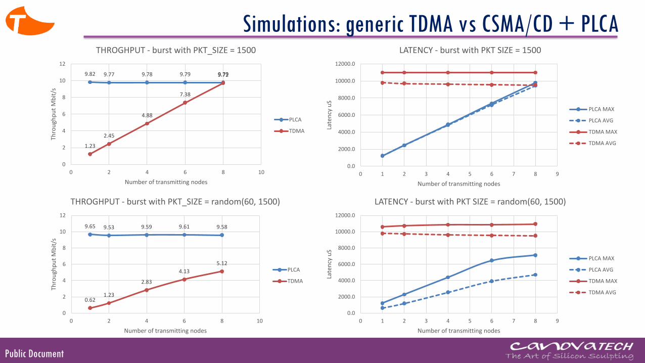
Simulations: generic TDMA vs CSMA/CD + PLCA
9.82 9.77 9.78 9.79 9.79
1.23
2.45
4.88
7.38
9.72
0
2
4
6
8
10
12
0 2 4 6 8 10
Thro
ugh
pu
t M
bit
/s
Number of transmitting nodes
THROGHPUT - burst with PKT_SIZE = 1500
PLCA
TDMA
9.65 9.53 9.59 9.61 9.58
0.621.23
2.83
4.13
5.12
0
2
4
6
8
10
12
0 2 4 6 8 10
Thro
ugh
pu
t M
bit
/s
Number of transmitting nodes
THROGHPUT - burst with PKT_SIZE = random(60, 1500)
PLCA
TDMA
0.0
2000.0
4000.0
6000.0
8000.0
10000.0
12000.0
0 1 2 3 4 5 6 7 8 9
Late
ncy
uS
Number of transmitting nodes
LATENCY - burst with PKT SIZE = 1500
PLCA MAX
PLCA AVG
TDMA MAX
TDMA AVG
0.0
2000.0
4000.0
6000.0
8000.0
10000.0
12000.0
0 1 2 3 4 5 6 7 8 9
Late
ncy
uS
Number of transmitting nodes
LATENCY - burst with PKT SIZE = random(60, 1500)
PLCA MAX
PLCA AVG
TDMA MAX
TDMA AVG
Public Document
Backward
compatibility
Public Document
What about existing MAC implementations?
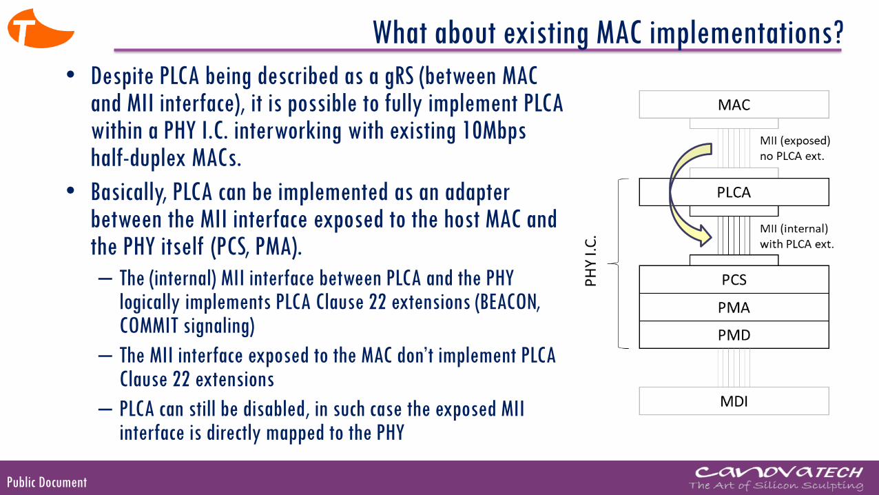
• Despite PLCA being described as a gRS (between MAC and MII interface), it is possible to fully implement PLCA within a PHY I.C. interworking with existing 10Mbps half-duplex MACs.
• Basically, PLCA can be implemented as an adapter between the MII interface exposed to the host MAC and the PHY itself (PCS, PMA).
– The (internal) MII interface between PLCA and the PHY logically implements PLCA Clause 22 extensions (BEACON, COMMIT signaling)
– The MII interface exposed to the MAC don’t implement PLCA Clause 22 extensions
– PLCA can still be disabled, in such case the exposed MII interface is directly mapped to the PHY
Public Document
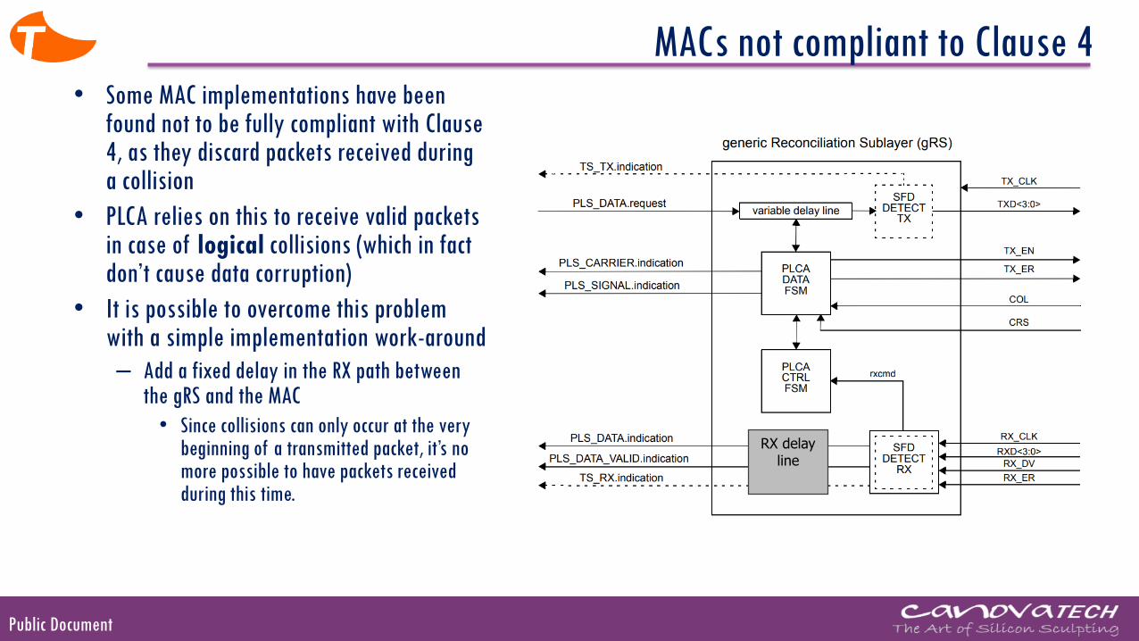
MACs not compliant to Clause 4• Some MAC implementations have been
found not to be fully compliant with Clause 4, as they discard packets received during a collision
• PLCA relies on this to receive valid packets in case of logical collisions (which in fact don’t cause data corruption)
• It is possible to overcome this problem with a simple implementation work-around
– Add a fixed delay in the RX path between the gRS and the MAC
• Since collisions can only occur at the very beginning of a transmitted packet, it’s no more possible to have packets received during this time.
RX delayline
Public Document
Demo

Public Document
10BASE-T1S Prototype Board
• Commercial MAC embedded in MPC8306 CPU
• Digital RTL synthesized in FPGA
• AFE in discrete components
ETH0
ETH
1
DISCLAIMER: The 10BASE-T1S prototype board is nota commercial product. It has been developed by Canova Tech S.r.l. for the sole purpose of developing and validating 10BASE-T1S IEEE specifications.
Public Document
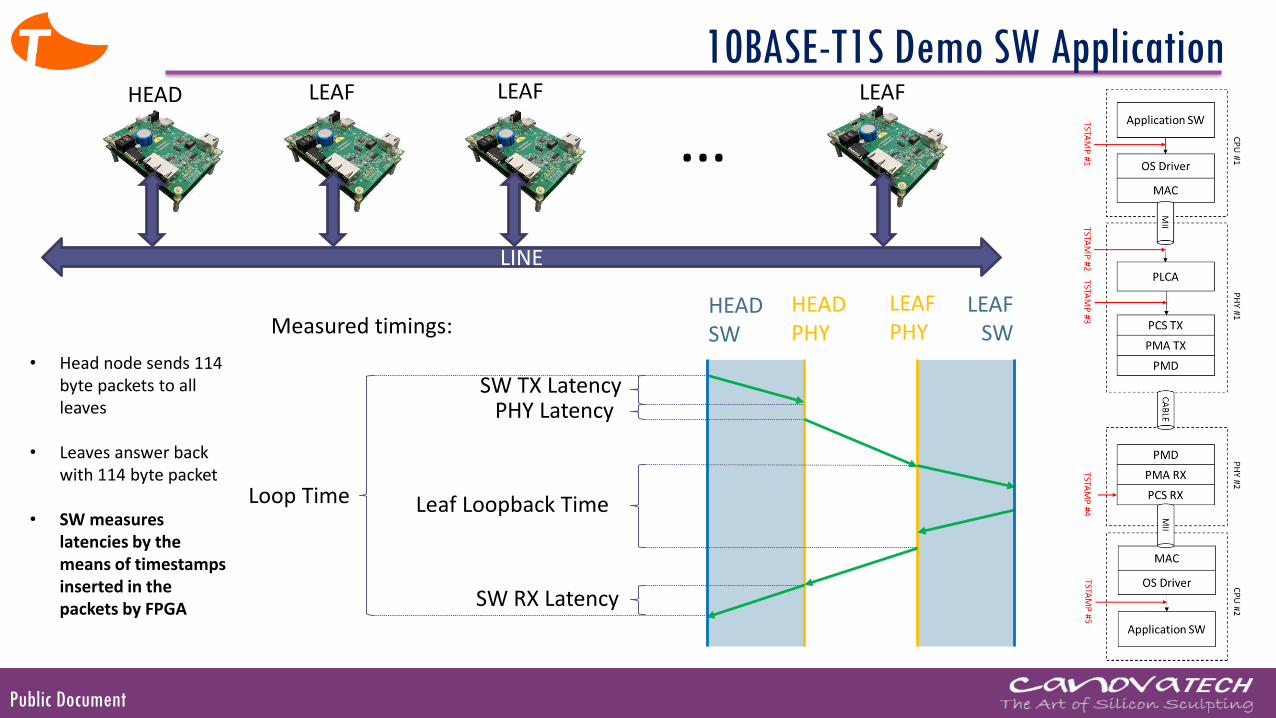
10BASE-T1S Demo SW Application
LINE
…HEAD LEAF LEAF LEAF
HEADSW
HEADPHY
LEAFPHY
LEAF SW
SW TX LatencyPHY Latency
Leaf Loopback Time
SW RX Latency
Loop Time
• Head node sends 114 byte packets to all leaves
• Leaves answer back with 114 byte packet
• SW measures latencies by the means of timestamps inserted in the packets by FPGA
Measured timings:
Public Document
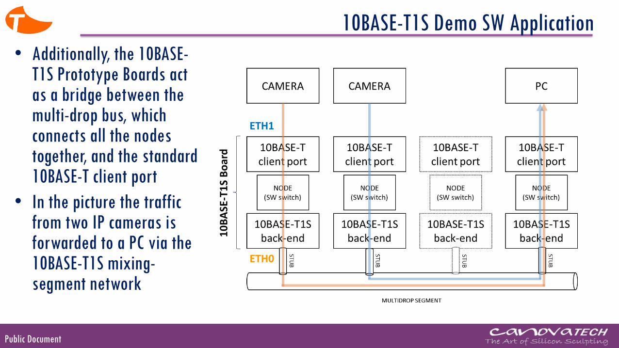
10BASE-T1S Demo SW Application
• Additionally, the 10BASE-T1S Prototype Boards act as a bridge between the multi-drop bus, which connects all the nodes together, and the standard 10BASE-T client port
• In the picture the traffic from two IP cameras is forwarded to a PC via the 10BASE-T1S mixing-segment network
10
BA
SE-T
1S
Bo
ard
ETH1
ETH0
Public Document
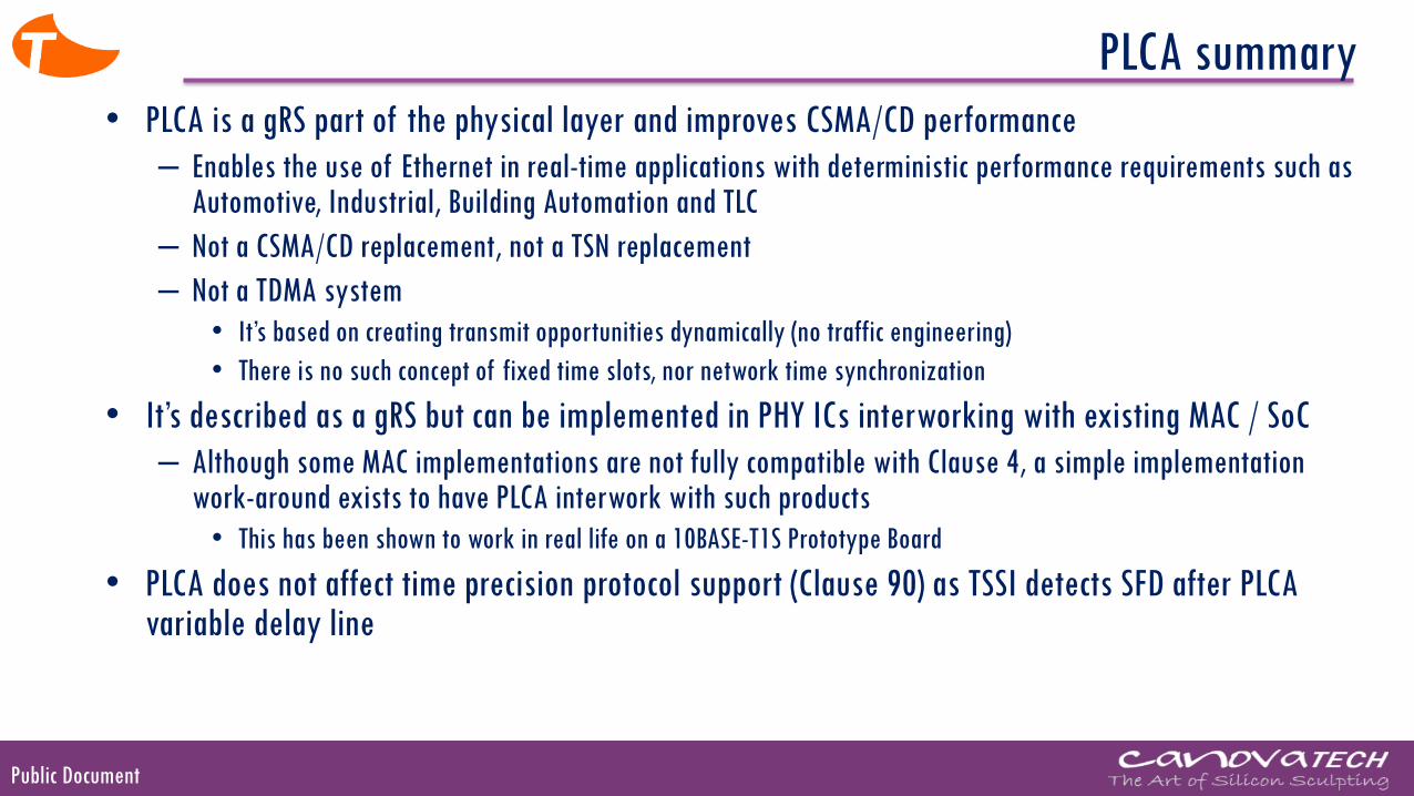
PLCA summary
• PLCA is a gRS part of the physical layer and improves CSMA/CD performance
– Enables the use of Ethernet in real-time applications with deterministic performance requirements such as Automotive, Industrial, Building Automation and TLC
– Not a CSMA/CD replacement, not a TSN replacement
– Not a TDMA system
• It’s based on creating transmit opportunities dynamically (no traffic engineering)
• There is no such concept of fixed time slots, nor network time synchronization
• It’s described as a gRS but can be implemented in PHY ICs interworking with existing MAC / SoC
– Although some MAC implementations are not fully compatible with Clause 4, a simple implementation work-around exists to have PLCA interwork with such products
• This has been shown to work in real life on a 10BASE-T1S Prototype Board
• PLCA does not affect time precision protocol support (Clause 90) as TSSI detects SFD after PLCA variable delay line

Public Document
THANK YOU!


![EJGF/V]F/DE>p@B8I9&FAL,JGNOJ - Piergiorgio Odifreddi · a no>ad v! > > ! 4 > = = =](https://static.fdocuments.in/doc/165x107/5c68dc4c09d3f2e4258c03d4/ejgfvfdepb8i9faljgnoj-piergiorgio-a-noad-v-4-.jpg)