Polarized sunglasses. "buy now, pay later" (Customer Pay After Delivery)

i
Abstract Technology is changing rapidly and there is need to adjust so as to improve the economy and
how businesses operate in Zimbabwe. This research gives a detailed overview of the Pick n Pay
Self-Service Mobile application with the main thrust of solving the problems of having long
queues customers waiting to pay up goods, customers spending much than they have budgeted
and increase in stationary costs during business operation, at the same time with the main of
implementing new technologies in Zimbabwe that will help improve our economy through the
improvement of business operations. The system will enable customers to purchase groceries
through the scanning of barcodes using android smart phones and a virtual receipt being
generated soon after payments of commodities. The system has a windows based application that
will be used for the creation of account and product pricing by the internal users of Pick n Pay
stores, and also it has a mobile application that will act as an interface between customer and the
system resources. Researcher used interviews, questionnaires and observation scorecards as
methodologies to acquire information that would help in system development. A windows based
application was developed using CSharp programming language while the mobile application
was developed using java. Major reason for carrying out the research is to curb the problems of
the current system highlighted above at the same time increasing organizational sales.

ii
Declaration I, RUMBIDZAI RASHEL MASVINGISE, do hereby declare that l am the sole author of this
thesis. I authorize Midlands State University to lend this dissertation to other individuals and
institutions for the purpose of scholarly research.
Signature_____________________________________________________________
Date_________________________________________________________________

iii
Approval The dissertation entitled “Pick n Pay Customer Self-Service Mobile Application” by Rumbidzai
Rashel Masvingise meets the regulations governing the award of the degree BSc Honors degree
in Information Systems by the Midlands State University. It has been approved for its
contribution to intellectual knowledge and literal presentation.
Supervisor__________________________________________________________
Date_______________________________________________________________

iv
Acknowledgements So much thanks to the Lord Almighty, who has always been the shield and the route to which l
followed to reach this far in life, my soul will always magnify his name. And also my sincere
gratitude goes to my supervisor Mr P. Denhere for his support and guidance throughout my
project research. I would also want to thank the Pick n Pay holding team for their unwavering
support in my research since they assisted me with all the information l required. Special thanks
to my group members Wellington Mandizvidza, Kudakwashe Jena, Sandra Chiraga, Emmanuel
Mdhlongwa and Beauty Musemwa, they have been so supportive in terms of advice, ideas and
assistance. The team spirit made us pull through with that vision of success and our motto “what
others can do, we can do better” has made us reach were we are today. My gratitude also goes to
my Uncle Mr P. Mupfiga, he has always been my mentor and made me believe that nothing is
impossible so long you work hard and nothing can ever be a barrier to success. Finally all thanks
goes to my father and mother for all the sacrifices they made with the sole aim of making me
successful as far as education is concerned. I greatly appreciate, may the Almighty bless you.

v
Dedication I would want to dedicate this to my lovely and caring Mother, Mrs V. Masvingise, words alone
cannot show how much l appreciate your efforts but the grace of God shall be with you always
and my prayers will always be to wish the best for you. You were my pillar of strength when l
was weak and your advices made me reach this far. My love for you will never fade and the Lord
will continue blessing you abundantly for all your good works.

vi
TABLE OF CONTENTS Abstract ......................................................................................................................................................... i
Declaration................................................................................................................................................... ii
Approval ..................................................................................................................................................... iii
Acknowledgements .................................................................................................................................... iv
Dedication .................................................................................................................................................... v
Table of Contents ………………………………………………………………………………………...vi
List of acronyms .......................................................................................................................................... x
List of Tables .............................................................................................................................................. xi
List of Figures ............................................................................................................................................ xii
CHAPTER ONE: INTRODUCTION ....................................................................................................... 1
1.1 INTRODUCTION ............................................................................................................................. 1
1.2 BACKGROUND OF THE STUDY ................................................................................................. 1
1.2.1 Organizational Background ...................................................................................................... 1
1.2.2 Organizational Structure .......................................................................................................... 2
1.2.3 Company Vision ......................................................................................................................... 2
1.2.4 Mission Statement ...................................................................................................................... 2
1.2.5 Company Values ........................................................................................................................ 2
1.3 PROBLEM DEFINITION ............................................................................................................... 3
1.4 PROJECT AIM ................................................................................................................................. 3
1.5 OBJECTIVES OF THE STUDY ..................................................................................................... 3
1.6 INSTRUMENTS ............................................................................................................................... 4
1.7 SYSTEM JUSTIFICATION ............................................................................................................ 4
1.8 SYSTEM FUNCTIONALITY ......................................................................................................... 4
1.9 CONCLUSION ................................................................................................................................. 5
CHAPTER TWO: PLANNING PHASE .................................................................................................. 6
2.1 INTRODUCTION ............................................................................................................................. 6
2.2 REASONS FOR BUILDING THE SYSTEM ................................................................................ 6
2.3 BUSINESS VALUE ANALYSIS ..................................................................................................... 7
2.3.1 Customer Value .......................................................................................................................... 7
2.3.2 Channel Partner Value .............................................................................................................. 7
2.3.3 Employee Value .......................................................................................................................... 7
2.3.4 Managerial Value ....................................................................................................................... 8

vii
2.4 FEASIBILITY STUDY ANALYSIS ............................................................................................... 8
2.4.2 Economic Feasibility .................................................................................................................. 9
2.4.3 Social Feasibility ....................................................................................................................... 14
2.4.4 Operation Feasibility ............................................................................................................... 14
2.5 RISK ANALYSIS ............................................................................................................................ 16
2.5.1 Market Risk .............................................................................................................................. 16
2.5.2 Performance Risk ..................................................................................................................... 16
2.5.3 Implementation Risk................................................................................................................ 16
2.6 DEVELOPMENT OF A WORKPLAN ........................................................................................ 17
2.6.1 GANTT CHAT ......................................................................................................................... 17
2.7 CONCLUSION ............................................................................................................................... 18
CHAPTER THREE: ANALYSIS PHASE ............................................................................................. 18
3.1 INTRODUCTION ........................................................................................................................... 18
3.2 INFORMATION GATHERING TECHNIQUES ....................................................................... 18
3.2.1 Interviews .................................................................................................................................. 18
3.2.2 Questionnaires .......................................................................................................................... 20
3.2.3 Observations ............................................................................................................................. 22
3.3 ANALYSING THE EXISTING SYSTEM ................................................................................... 23
3.3.1 Inputs ........................................................................................................................................ 23
3.3.2 Processes ................................................................................................................................... 23
3.3.3 Outputs ...................................................................................................................................... 23
3.4 PROCESS ANALYSIS ................................................................................................................... 24
3.4.1 Activity Diagram ...................................................................................................................... 24
3.5 DATA ANALYSIS .......................................................................................................................... 25
3.5.1 Context Diagram ...................................................................................................................... 25
3.5.2 Data Flow Diagram For Current System ............................................................................... 26
3.6 WEAKNESSES OF THE CURRENT SYSTEM ......................................................................... 27
3.6.1 Strengths Of The Current System .......................................................................................... 27
3.7 EVALUATION OF ALTERNATIVES ........................................................................................ 28
3.7.1 Outsourcing .............................................................................................................................. 28
3.7.2 Improving The Current System .............................................................................................. 29
3.7.3 In-House Development ............................................................................................................ 29
3.7.4 Conclusion Of Analysis ............................................................................................................ 30

viii
3.8 REQUIREMENTS ANALYSIS..................................................................................................... 30
3.8.1 Functional Requirements ........................................................................................................ 30
3.8.2 Non-Functional Requirements ................................................................................................ 32
3.9 CONCLUSION ............................................................................................................................... 32
CHAPTER FOUR: SYSTEM DESIGN .................................................................................................. 33
4.1 INTRODUCTION ........................................................................................................................... 33
4.2 PROPOSED SYSTEMS DESIGN ................................................................................................. 33
4.2.1 Major Systems Functionalities ................................................................................................ 34
4.2.2 Proposed Systems Description Design Overview .................................................................. 35
4.2.3 Proposed Systems Context Diagram ...................................................................................... 35
4.2.4 Proposed Systems Dataflow Diagram .................................................................................... 36
4.3 ARCHITECTURAL DIAGRAM .................................................................................................. 38
4.3.1 Client Server Approach ........................................................................................................... 39
4.4 PHYSICAL DESIGN ...................................................................................................................... 40
4.5 DATABASE DESIGN .................................................................................................................... 40
4.5.1 Database Design Architecture ................................................................................................. 40
4.5.2 Data Modeling .......................................................................................................................... 42
4.6 PROGRAM DESIGN ..................................................................................................................... 47
4.6.1 Package Diagram ..................................................................................................................... 47
4.6.2 Class Diagram .......................................................................................................................... 49
4.6.3 Sequence Diagram.................................................................................................................... 50
4.7 INTERFACE DESIGN ................................................................................................................... 51
4.7.1 Fundamental Structure Design ............................................................................................... 51
4.7.2 Security Design ......................................................................................................................... 51
4.7.3 Main Menu Form ..................................................................................................................... 53
4.8 CONCLUSION ............................................................................................................................... 57
CHAPTER FIVE: IMPLEMENTATION PHASE ................................................................................ 58
5.1 INTRODUCTION ........................................................................................................................... 58
5.2 CODING .......................................................................................................................................... 58
5.3 TESTING ......................................................................................................................................... 58
5.3.1 Unit Testing .............................................................................................................................. 59
5.3.2 Module Testing ......................................................................................................................... 61
5.3.3 Subsystem Testing .................................................................................................................... 62

ix
5.3.4 System Testing .......................................................................................................................... 62
5.3.5 Acceptance Testing .................................................................................................................. 62
5.3.6 Testing Strategies ..................................................................................................................... 63
5.4 INSTALLATION ............................................................................................................................ 69
5.4.1 User Training ........................................................................................................................... 69
5.4.2 Operation Environment .......................................................................................................... 70
5.5 CONVERSION ............................................................................................................................... 70
5.5.1 System Change Over ................................................................................................................ 70
5.5.2 Recommended Change Over Strategy ................................................................................... 72
5.6 MAINTANANCE ............................................................................................................................ 72
5.6.1 System Review .......................................................................................................................... 73
5.6.2 Disaster Recovery ..................................................................................................................... 74
5.6.3 System Backup ......................................................................................................................... 75
5.6.4 System Evaluation .................................................................................................................... 76
5.6.5 Constraints ................................................................................................................................ 85
5.6.6 Recommendations .................................................................................................................... 85
5.7 CONCLUSION ............................................................................................................................... 85
BIBLIOGRAPHY ................................................................................................................................. 87
APPENDIX A: USER MANUAL ............................................................................................................ 89
APPENDIX B: INTERVIEW CHECKLIST ......................................................................................... 97
APPENDIX C: QUESTIONNAIRE ........................................................................................................ 98
APPENDIX D: OBSERVATION FORM ............................................................................................. 100
APPENDIX E: SAMPLE CODE ........................................................................................................... 101
x
List of acronyms Php Hypertext Preprocessor
SQL Standard Query language
CBA Cost Benefit Analysis
ROI Return On Investment
Sms Short Message Service
DFD Data Flow Diagram
ER Entity Relationship
EER Enhanced Entity Relationship
SDLC Software Development Life Cycle

xi
List of Tables Table 1: Client computer
specifications…………………………………………………………...8
Table 2: Software
Specifications…………………………………………………………………..9
Table 3: Tangible
benefits………………………………………………………………………..10
Table 4: Intangible
benefits………………………………………………………………………11
Table 5: Expected development costs……………………………………………………………11
Table 6: Expected operational
costs……………………………………………………………...12
Table 7: Cost Benefit
Analysis…………………………………………………………………...12
Table 8: Return on
investments…………………………………………………………………..13
Table 9: Work
plan……………………………………………………………………………….17
Table 10: Alternative analysis
table………………………………………………………………29
Table 11: Client
registration……………………………………………………………………...43
Table 12: Adding new products………………………………………………………………….44
Table 13: User account
details……………………………………………………………………44
xii
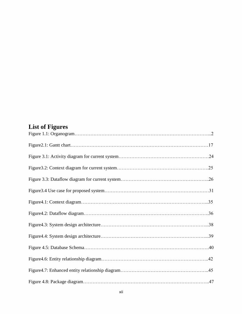
List of Figures Figure 1.1: Organogram…………………………………………………………………………...2
Figure2.1: Gantt chart……………………………………………………………………………17
Figure 3.1: Activity diagram for current system…………………………………………………24
Figure3.2: Context diagram for current system………………………………………………….25
Figure 3.3: Dataflow diagram for current system………………………………………………..26
Figure3.4 Use case for proposed system…………………………………………………………31
Figure4.1: Context diagram……………………………………………………………………...35
Figure4.2: Dataflow diagram…………………………………………………………………….36
Figure4.3: System design architecture…………………………………………………………...38
Figure4.4: System design architecture…………………………………………………………...39
Figure 4.5: Database Schema…………………………………………………………………….40
Figure4.6: Entity relationship diagram…………………………………………………………..42
Figure4.7: Enhanced entity relationship diagram………………………………………………..45
Figure 4.8: Package diagram……………………………………………………………………..47

xiii
Figure4.9: Class diagram………………………………………………………………………...48
Figure 4.10: Sequence diagram…………………………………………………………………..49
Figure4.11: Personnel login form………………………………………………………………..51
Figure4.12 Customer login form…………………………………………………………………51
Figure4.13:Creating user account form………………………………………………………….52
Figure4.14: Customer registration form…………………………………………………………53
Figure4.15: Adding new product………………………………………………………………...53
Figure4.16: Products report……………………………………………………………………...54
Figure 4.17: Customer List report………………………………………………………………..54
Figure4.18: Account balance report……………………………………………………………...54
Figure4.19: Sales report………………………………………………………………………….55
Figure4.20: Customer order list………………………………………………………………….55
Figure4.21: Customer account balance…………………………………………………………..56
Figure5.1: Testing stages………………………………………………………………………...58
Figure5.2: Black box testing……………………………………………………………………..59
Figure5.3: White box testing……………………………………………………………………..60
Figure5.4: Customer login……………………………………………………………………….62
Figure5.5: Internal user login…………………………………………………………………….63
Figure5.6: User login fails……………………………………………………………………….63
Figure.7: Customer registration………………………………………………………………...64
Figure5.8: Sales rep registration…………………………………………………………………64
Figure5.9: Success login pop up message………………………………………………………..65
Figure5.10: Test case one………………………………………………………………………..66

xiv
Figure5.11: Test case two………………………………………………………………………..67
Figure5.12: Adding products…………………………………………………………………….68
Figure5.13: Steps in system maintenance activity diagram……………………………………...72
Figure5.14: Start shopping interface……………………………………………………………..76
Figure5.15: Barcode scanner details……………………………………………………………..76
Figure 5.16: Order list……………………………………………………………………………77
Figure5.17: Payment information………………………………………………………………..78
Figure5.18: Virtual sms receipt…………………………………………………………………..79
Figure5.19: System interfacing…………………………………………………………………..80
Figure5.20: Adding new customer……………………………………………………………….80
Figure5.21: Adding new product………………………………………………………………...81
Figure5.22: Adding new user…………………………………………………………………….81
Figure5.23 Managing products…………………………………………………………………..82
Figure5.24: Customer report……………………………………………………………………..83
Figure 5.25: Sales report…………………………………………………………………………83

xv

1
CHAPTER ONE: INTRODUCTION
1.1 INTRODUCTION
Technology is changing rapidly in the world of today and it is of paramount importance for an
organization to find ways of improving customer support service facilities with an attempt of
being the best service providers at the same time being the world‟s best market as compared to
its competitors. The purpose of the study is to give an introductory lineup with the main intention
of the development of an online customer self-service mobile application for Pick n Pay stores. It
is an automated system with the main thrust of improving organizational efficiency through
quality and instant service to its customers. The chapter will highlight the background of the
research, problem definition, significance, objectives, and hypothesis together with the
justification to system development.
1.2 BACKGROUND OF THE STUDY
An analysis was made concerning the operations of the activities of Pick n Pay starting from the
time a customer enters the shop till he or she queues at the till to make payment and also, the
behavior of the managerial in system maintenance and updating. After all has been done, an
online customer self-service mobile application was found to be the best alternative to reducing
the level of congestion in the store and at the same time avoiding an over budget to the valid
customers. Instead of strenuous data base maintenance and system monitoring the self-service
application will save the self-monitoring purpose to both the organizational personnel and its
customers.
1.2.1 Organizational Background
Pick n Pay is an investment holding company with sole purpose of controlling shareholdings of
Pick n Pay stores. It operates in the retail sector and its major focus is on the customer. The
founder was Raymond Ackerman who spread his works in various parts around Africa. Major
concern is on groceries, clothing and merchandise, including value added services to cater for the
customer‟s desires. It aims at doing things that help its customers and community by providing
affordable and quality food stuff. As a result of doing well in business, efficiency and customer
sovereignty Pick n Pay has grown rapidly for the past years.

2
1.2.2 Organizational Structure
The organizational structure shows the relationship between members at Pick n Pay, their
positions and line of formal communications. This is shown in the figure below:
Figure 1.1: Organogram
1.2.3 Company Vision
To support and encourage Africans to be sole providers and focus on improving their lives and
be contributors to the community.
1.2.4 Mission Statement
Serving our clients wholeheartedly and creating a favorable environment for them. Through the
use of our mindset, an admirable place to shop is created.
1.2.5 Company Values
Passionate about customers will
Supporting customer rights.
Respect and care for customers and personnel.
Focus on personal growth and opportunity.
Reward innovation and nurture leadership.
Integrity and honesty at all cost.
Participate and Support in the community.
Responsibility as an individual at all aspects.

3
Accountable for any issues at hand
1.3 PROBLEM DEFINITION
The current retail system uses the conventional system:
Customers visit the shop and collect required goods in a basket and then visit the till where the
goods are paid for. This process has got the following challenges:-
Some customers may pick up goods above their budget and this can only be discovered at
the till.
More time is used during the input of the goods on the till and this increases queues.
Stationery costs are higher since it involves printing of receipts.
1.4 PROJECT AIM
The major aim of the research is to develop a customer self-service application for Pick n Pay
that enables customers to scan products bar codes, get the price, send payment online, generate a
receipt and walk out without having to queue for payments.
1.5 OBJECTIVES OF THE STUDY
The objectives of the study it to design a mobile application that:
Allows customer self-service where by a customer through a smart mobile device will
add goods in a virtual basket, manage the basket, add to and remove product from the
cart.
Enables the viewing of the goods bought and make a payment through the mobile device
using WIFI.
Interfaces the customer self-service mobile application to the windows application so that
the goods purchased by the customer are updated in the inventory database.
Makes it possible for the Sales Manager to be able to add manage products, create and
manage customers, create and manage users.
Display reports which include sales reports and customer‟s reports.
Improve Customer Relationship Management by showing high spending customers and
rewarding them.

4
1.6 INSTRUMENTS
JAVA - It is an object oriented programming language that will be used for the Mobile
Application.
C# - It is a programing language that will be used for the desktop application.
Sql Server – this will work as a database to which the project will be created and will
work as a storage repository where data will be retrieved.
IIS – Webserver – this will be used to host web services.
1.7 SYSTEM JUSTIFICATION
Reduction of costs of labor
Instead of the till operators working on tills saving customers, their works will be
replaced by the customer due to the presence of the self-service application.
Customers who prefer being helped by the cashier can still have the privilege to do so and
those who are not interested can opt for self-checkout.
Self-service does not use up a lot of space
Customer transactions are easy to control and monitor since all is done at the back end
hence less space is occupied since many shops can be placed in a small area and
monitored.
Efficiency and Speed of Checkout
Speed in service is increased since customers just scan bar codes and pay using a virtual
debit card instead of having to wait in long queues to be served by the cashier.
Less Subordinates to pay
Instead of paying many cashiers and increasing organizational costs, especially when a
few customers are using the tills, it will be of paramount importance to flatten the cashier
team since less or no work at all is done hence reducing salary costs.
1.8 SYSTEM FUNCTIONALITY
The customer is going to be registered for a mobile application account by the
administrator and provided with a card number which will be linked to the Pick n Pay
Shop easy shopping voucher debit card.

5
Customer provides funds which will be loaded into in the card by the administrator.
The customer will then register his card on the mobile application and once registered the
customer can begin shopping
Using a camera phone a customer scans bar codes of products and add them in the virtual
basket, the same product is also placed in the physical basket or cart generating product‟s
cost.
The mobile application basket gets updated with each product added or deleted from the
basket and it must provide a customer with the current balance of goods selected.
The customer makes a payment for the goods which must deduct the balance deposited at
first by the customer.
A virtual receipt must show on the application and SMS notification sent to customer.
1.9 CONCLUSION
Focus was on highlighting an introduction involving giving a brief outline on the company‟s
history, identification of the problem and possible solutions to the problems. The methodologies
to be used were outlined together with a clear justification to support the proposed idea in
problem solving. We then move on to the next chapter were we will look at the visibility and
viability of the proposed project to see if it is worthy doing.

6
CHAPTER TWO: PLANNING PHASE
2.1 INTRODUCTION Planning involved the developer understanding the costs of carrying out the study in relation to
the benefits the system is intended to provide. Stoner (2001) defined planning as an act of
formulating a program. Feasibility study looks at the organizational business value and the
percentage to which the project is going to increase the value of the business and its operation. It
performs the appraisal to evaluate the worthiness of carrying out the project. Basically it looks
at:-
Why we should build the system
Identifying the business value
Feasibility analysis
Projects work plan
All activities of the study are directed to answer the question, Should we proceed with the
project? And the planning phase will help us answer in.
2.2 REASONS FOR BUILDING THE SYSTEM
The main aim of the development of the proposed system was due to the identification of the
problems in use of the current system. Below are the various factors that justify why we should
develop a self-service application:-
It will help reduce labor costs since one attendant can often run four to six checkout lanes
with the work of the cashier now being assumed by the customer. Customers who do not
want to interact with the cashier or be a part of the queue where the current customer and
cashier are conversing can now use the self-checkout to avoid those situations.
Efficiency and Speed of Checkout is increased, instead of dealing with long lines that get
backed up by customers waiting to pay, people can quickly make purchases by scanning
items themselves.
Self-Checkouts take up less space because multiple kiosks can be placed into a relatively
small area, stores can take care of customer transactions with minimal space
7
Fewer employees to pay since cashiers aren‟t completing any tasks and are essentially
being paid for nothing due to the availability of the self-service application.
2.3 BUSINESS VALUE ANALYSIS
According to Sward (2006) business value is a term that includes forms of value or benefits that
determine the health and wellbeing of a firm. In this section we will identify the value of the
proposed system to various entities and we will also assess the positive and negative impact of
the proposed system in relation to the current system.
2.3.1 Customer Value
Since customers would have taken over the cashier position, time spent waiting in long queues is
reduced since one can now self-serve. At the same time impulse buying is reduced since
customers view the catalogue of existing products and they buy according to the budget of
moneys available in their virtual cards. Advertisement and promotions are viewed online without
having to visit Pick n Pay stores. An online solution means there is no time limit or a specific
location for information access hence promoting cost reduction of travel to customers.
2.3.2 Channel Partner Value
A channel partner is a company that partners with another organization or producer to sell its
products. Examples of Pick n Pay channel partners are Lyons, Dairiboard, Lobels, Irvines, Lever
brothers and many others. These also benefit from the use of the system in various ways.
Business efficiency is increased through product disposition and brand advertisement since all
updates are made known to customers at any given time so long they have the application
installed on their mobile phones. Products of channel partners are sold quickly and this making it
possible for them to supply more commodities.
2.3.3 Employee Value
Since the customer will reduce the interaction between employees and the customer, the system
is designed to meet a greater number of ever increasing customers therefore repetitive customer
service and delegation levels are reduced.
The proposed system will enable system synchronization, capturing of customer comments and
also purchase behavior patterns of customers hence helping them in segmenting the market
hence, improving profit margins and motivating employees.

8
Employee skills will be improved since training will be conducted to manage and maintain the
system and less effort will be required.
2.3.4 Managerial Value
The implementation of a customer self-service application will help reduce employment rate and
will also flatten the organizational structure. Therefore instead of long hierarchical levels, the
system becomes a supplement for efficiency and productivity of the organization. And also,
instead of monitoring many employees or cashiers on how they are performing, the customer
becomes a „cashier‟ and the management only plays a role of monitoring systems and digital
receipts of customers.
2.4 FEASIBILITY STUDY ANALYSIS
Feasibility study analyses the practicality of a customer self-service application assessing the
possible pros and cons attached to it if we were to implement it at Pick n Pay. According to Hall
(1962), feasibility study is a report that leads to a choice of one amongst two or more
alternatives. It evaluates the various reflections that lead to particular perceptions in decision
making. Feasibility study formalizes the openness of brainstorming process. In feasibility, the
problem is carefully described, risks are looked at in relation to the proposed system. Later,
decisions on what to accept are influenced on the outcome of the feasibility study. In many cases,
in the form of an impact assessment statement, feasibility study provides the basis for action by
funding agencies. A well done feasibility study should give a decision on whether further action
is desirable and should be able to convince others as well.
2.4.1 Technical Feasibility
Processor Pentium 4
Ram 512mb Or Better
Cache 512mb
Hard disk 50gig
Table 1: Client Computer Specifications

9
Operating System Windows 7/8/10
Server Side IIS Web Server
Client Side Html, Java Script
Client Side Scripting language Java Script
Services JSON REST Web Services
Database Ms Server
Programming Language Java, C#
Web Applications Asp.Net
IDE/ Workbench Eclipse
Table 2: Software Specifications
2.4.2 Economic Feasibility
Economic feasibility analysis help analyze the positive economic benefits to be provided by the
proposed system to the organization. Assessment usually involve cost and benefit analysis and
the business case analysis. If the costs outweigh the benefits then the project will be put to a halt.
It will also have a look at tangible and intangible benefits, development and operational costs and
the time taken to recoup the initial capital invested if project is to be developed.
2.4.2.1 Business Case Analysis
Business case assesses the environment to which the business is running. It also takes a further
look at the business nature, customer type, current payment process and expected time required
to perform a transaction. Analysis of the business case done by Pick n Pay helped identify the
benefits that are to be gained through the implementation of the proposed project. It also gave the
organization a platform to reason upon the economic feasibility assumptions stated hence
obtaining the advantages and disadvantages of implementing or not implementing the system.

10
2.4.2.2 Cost Benefit Analysis
This gives an assessment of the costs and benefits that are to accrue if the system is to be
implemented. In actual sense, costs should not outweigh benefits. However if this eventually
happens, the project will be said to be not feasible. Some of the benefits will not be in monetary
form therefore, these are to be converted into monetary form so as to have clear figures for
proper analysis and comparison. This will help the organization to see if they are financially
strong to proceed with the proposed project from the development up to the maintenance phase.
2.4.2.2 Tangible Benefits
Reduced calculation and processing errors
Reduction in financial loses
Improved productivity and efficiency
Improved information availability and accuracy
Reduction in communication hierarchy
The table below will outline the estimated tangible benefits in monetary terms:-
Annually expected tangible benefits (US$) Amount (US$) Total
Reduced calculation and processing
errors
3 000
Reduction in financial loses 3 500
Improved productivity and efficiency 1 000
Reduction in communication hierarchy 800
Information availability and accuracy 5 000
Expected annual benefit 13 300
Table 3: Tangible Benefits
2.4.2.3 Intangible Benefits
Technology diversification and appreciation
Improved decision making capabilities

11
Increase in information quality
Increase in staff motivation and morale
Increase in customer loyalty
Increase in competitive advantage due to service differentiation
Annually expected intangible benefits (US$) Amount (US$) Total
Technology diversification and appreciation 1 500
Improved decision making capabilities 1 500
Increase in information quality 3 500
Increase in staff motivation and morale 500
Increase in customer loyalty 900
Increase in competitive advantage due to service
differentiation
4 000
Expected annual benefit 11 900
Table 4: Intangible Benefits
2.4.2.4 Cost Of Development
These are the estimated costs to be accrued during the development process. These are to be
estimated before the project begins basing on the phases to be followed up to project completion.
These are shown below:-
Development team
Staff training
Equipment
Customer awareness
Information supply
Installation
The table below shows the development costs in monetary terms:-
Annually expected development costs (US$) Amount (US$) Total

12
Development team 4 000
Staff training 1 500
Development equipment 1 000
Customer awareness 500
Information supply 1 000
Installation 2 000
Expected annual costs 10 000
Table 5: Expected Development Costs
2.4.2.5 Operational Costs
These are costs that are incurred in the daily operational use of the system. These costs are
divided into fixed cost (those that are not directly linked to production and remain the same) and
variable costs (those that are directly linked to system performance and use). These cost
estimates will be shown in the table below:-
Annually expected operational costs (US$) Amount (US$) Total
Server upgrade 600
Backup plan 300
Conversion costs 1 200
Software upgrade 700
System maintenance 500
Training costs 1 300
Expected annual cost 4 600
Table 6: Expected Operational Costs
2.4.2.6 Overview Of Cost Benefit Analysis
This will show the overall benefits and costs of the proposed project that will lead to the decision
of whether the project is viable or not.
Cost and Benefit (US$)Amount (US$) Amount (USD) Amount

13
COSTS
Development costs 10 000
Operational costs 4 600
Total Costs (14 600)
BENEFITS
Tangible 13 300
Intangible 11 900
Total benefits 25 200
NET BENEFITS 10 600
Table 7: Cost Benefit Analysis
2.4.2.7 Return On Investment
Return on investment is a performance measure used to evaluate an investment efficiency or
comparing the efficiency of a number of different investments. It measures the amount of return
to an investment cost. It is measured as a percentage. In this case the researcher will do a 3 year
comparison using Return on Investment and is calculated as:-
Return on investments = Net benefits * 100
Total costs
2015 2016 2017
COSTS 10600 11000 12600
BENEFITS 14600 14000 13500
ROI 72.6% 78.6% 93.3%
Table 8: Return On Investment
Explanation on statistics

14
The estimated costs and benefits from 2015 to 2017 show that the return on investment of the
project will increase as the project continues to be in use.
2.4.3 Social Feasibility
Analysis revealed that, the proposed system will impact the society both positively and
negatively.
POSITIVE IMPACT
To those who are more technical, it will help them reduce burdens of waiting long queues
and all that they do will be done on time since they will be serving themselves.
Those who are in possession of smart phones become smarter by being able to use their
gadgets for a more unique task of shopping for them.
The system will act as a wallet to the customers that will help them budget for their
groceries at any given time since it gives a platform of advance deposit in the virtual
debit card.
NEGATIVE IMPACT
It will be a great disadvantage with those without smart phones, they will feel as if they
are behind as compared to the others and might feel as if they do not fit buying from
there.
Some individuals are computer illiterate and some are old and will not have the privilege
to have a feel of the system.
SOLUTION
It will be of paramount importance to do a parallel implementation of the system so as to make
sure that most, if not all of the customers are used to the system before a direct changeover
strategy.
2.4.4 Operation Feasibility
For a system to be operationally feasible, there should be total support and involvement from
stakeholders throughout the project so as to be rest assured that there is operational
understanding of the system. This will also lead to the positive acceptance of the system to Pick
n Pay and users will definitely support in every way. The system will help the following users in
various ways:-

15
2.4.4.1 Operations Management
The operations management team were in full support of the project since they had the view that
it will improve business operation and efficiency instead of people spending much time waiting
in long queues. So due to the availability of the mobile application, customers can now save
themselves without much pressure at any given time. They also assured that they will convince
the rest of the organizational team on how vital the proposed system will be to the organization.
2.4.4.2 Sales Management
The sales management was greatly impressed with the proposed system since they have the view
that the system will increase their sales margin. This is so because customers want easy shopping
ways therefore by just getting into a shop and buying using your mobile phone it becomes easier
at the same time the system will help customer budget since they pay in advance and by using
their virtual debit cards, they automatically deduct their amount as they purchase hence reducing
cases of losing their moneys or theft crimes.
2.4.4.3 Finance Management
These were much concerned about the benefits that the company will get by implementing the
proposed system. They viewed it as if the resources required to set up the new system would cost
more than the current operations but after some further elucidations they did agree that, the
proposed system will reduce employment costs, and costs of having expired goods in store since
all the operations will be automated from the top management up to the customer.
2.4.4.4 Organizational Staff
The effectiveness of the system came to being after realizing that the system will reduce
routinely and monotonous tasks that will end up demotivating employees. Therefore, the self-
service mobile application will reduce the work load on employees since they will have few
people without smart phones or that are comfortable with the traditional way of purchasing to
attend to.
2.4.4.5 Customers
Most customers supported the system since they viewed it as a time conscious aid. Less labor
will be required for them each moment they got in store and also payment in advance is a better
way of budgeting according to their view.
2.4.4.6 ICT Management
They were greatly impressed with the idea because instead of them monitoring multiple systems,
the self-service application will act as an umbrella system in business operations and any

16
changes can be done easily without having to visit any till hence making them concentrate on
other better tasks.
2.5 RISK ANALYSIS
2.5.1 Market Risk
The brand, compliance and market exposure is determined by the system performance therefore
failure to comply to meet customer demands will have an impact on the suppliers or channel
partners of Pick n Pay. Therefore if the system fails to deliver updates to customers completely,
they will be looking forward to explanations from the organization thereby having an impact on
the marketing strategy of the organization.
Mitigation and Management
Determine the possible impact of compromise and find a backup plan in case of system poor
performance. Monitor the marketing lines so as to detect early warnings that might impact the
firm‟s goodwill and brand.
2.5.2 Performance Risk
This involves system performance in relation to ongoing supplier quality and financial issues.
Failure of system to work according to plan or failure of system to meet business objectives may
reduce organizational performance hence leading to an increase in costs, and at the same time
failure of customers and employees to use the system affects the ongoing performance of the
business.
Mitigation and Management
Continuous monitoring of system performance is required to avoid disruptions. Training and
awareness should be conducted to both employees and customers before system usage. Constant
vigilance is needed.
2.5.3 Implementation Risk
System implementation can lead to production and performance ramp if implemented before full
understanding of system performance by employees and customers.
Mitigation and Management
Instead of a full implementation of the system, it would be wiser to do a parallel implementation
of the system. As some use the old way of procurement and payment, others will be familiarizing

17
with the self-service application and they are fully familiar then a direct implementation can be
done. This will make customers feel comfortable to purchase at Pick n Pay hence maintaining
customer loyalty.
2.6 DEVELOPMENT OF A WORKPLAN
Task Start date Completion Duration
Project proposal 03/08/2015 09/08/2015 1 week
Planning phase 10/08/2015 23/08/2015 2 weeks
Analysis phase 24/08/2015 06/09/2015 2 weeks
Design phase 07/09/2015 27/09/2015 3 weeks
implementation 28/09/2015 04/10/2015 1 week
Evaluation 5/10/2015 11/10/2015 1 week
Documentation 03/08/2015 11/10/2015 10 weeks
Table 9: Workplan
2.6.1 GANTT CHAT
A Gantt chart is a representation of the project schedule that is the start and finish dates of the
different phases of development.
Activity/period(weeks) 1 2 3 4 5 6 7 8 9 10
Proposal
Planning phase
Analysis phase
Design phase
Implementation
Evaluation
Documentation
Figure 2.1: Gantt chart

18
2.7 CONCLUSION
After the project had been deemed viable, the researcher is now able to move to the design
phase. A work plan has been made and tasks are to be done within the stipulated time. Analysis
has been done to the current system and further more will be looked at in the next phase.
CHAPTER THREE: ANALYSIS PHASE
3.1 INTRODUCTION
Feasibility study showed us the costs and requirements of the proposed system. Analysis phase
answers the questions of who will make use of the proposed system, how the system will work,
and where and when it will be implemented (Dennis, 2002). Analysts will work with the users to
find out the user requirements and expectations to the proposed system. Output of the analysis
phase will give a brief outline of the analyzing team‟s alternative recommended solution in line
with user requirements. Once recommendation has been accepted then system design will begin.
(Hoffer, 2002). This phase will look at the current system functionality, process flows involved
and their coordination. The main functionality of the current system will be analyzed together
with the inputs, processes and outputs.
3.2 INFORMATION GATHERING TECHNIQUES
Information gathering is done so as to get a realistic view of system functionality from various
stakeholders who are directly and indirectly involved in system use. An information gathering
methodology provides with a sequence of steps involved in order to come up with the
requirements. Researcher made use of three fact finding techniques which are:
Interviews
Questionnaires
Observations
3.2.1 Interviews
An interview involves a conversation between two people, which is the interviewer and the
interviewee in order to acquire information pertaining to a certain topic of discussion. The
manager, sales representative and customers of Pick n Pay were interviewed so as to gather some
information. And main focus was on:-
19
locating the respondent
persuading them to answer questions
asking questions
recording answers
ensuring answers are meaningful
Ensuring the answers are the respondents‟ own.
There are two types of interviews which are structured and unstructured interviews.
3.2.1.1 Structured Interviews
A standardized (or structured) interview involves a procedural activity in which the same
question is asked exactly the same way and in the same order (Artkinson, 1964). Researcher used
this approach to interview mainly customers so as to get a clear view of different perceptions of
different customers towards the services they are being offered at pick n pay stores. This helped
in coming up with a qualitative and quantitative analysis of the views in relation to the
information being researched on.
3.2.1.2 Unstructured Interviews
Open ended interviews have no formal structure. Questions are asked in the same order and there
is room for discussion between interviewer and interviewee. This is normally done on topics
which are broad and require discussions. Researcher used this approach while interviewing the
management team and the ICT department. This was to help the researcher to have a broader
view on how the system operates and various defects the system holds. Giving room for
discussion also helped the management team to understand how the proposed system will
operate and if it will help increase organizational sales hence being deemed feasible.
3.2.1.3 Advantages Of Interviews
It enabled the interviewer to examine the posed topics hence having an in depth of the
required information before having to answer and also it gave room for discussion hence
making it more interactive between Pick n Pay personnel and the interviewer.
Asking the same questions in the same manner helped analyze the responses and makes it
easier to replicate discussion hence making it easier to regulate.

20
The use of interviews as a methodology made it easier to analyze how customers feel
about the services being offered and what they feel should be improved on the system
performance. Airing out of views was impressive since discussions where done and
individuals felt comfortable to take part.
3.2.1.4 Disadvantages Of Interviews
It was time consuming especially in the case of unstructured interview because every
individual wanted to stress his or her view about the system.
Some managerial members and customers where not willing to spare their time and take
part because they were in a hurry.
Quality of information gathered is determined by the quality of questions therefore, not
all that was required was gathered by this methodology.
Preplanning wasn‟t taken into consideration by the researcher hence some questions
where just asked as the interview was progressing having an effect of ending up
discussing irrelevant stuff.
3.2.1.5 Findings From Interviews
Researcher interviewed various stakeholders both internal and external and analyzed their views
toward the current and proposed system. She realized that to some Pick n Pay customers, the
current system was more favorable and understandable as compared to the proposed were as
some saw it as a huge step to innovation that will reduce the burden of long queues. Basing on
the customer survey, the sales management agreed to the system since they foresee it causing a
rise in sales figures as compared to that of the current management. However some of the
members of the management team continued to stress out that the current system was the best for
them and the top management was impressed with the functionality of the proposed system.
3.2.2 Questionnaires
Bell (1999) states that a questionnaire is a structured series of questions used for data collection
which are given to respondents so as to provide the answers. Such a methodology is used in areas
where individuals have no time for interviews and when anonymity is greatly required.
Questionnaires are used to collect both qualitative and quantitative data that will be used for
statistical analysis. There are two types of questionnaires which are open ended and closed
ended.

21
3.2.2.1 Open Ended Questionnaires
These are questions that require answers with explanations and are normally associated with the
questions why or how. These are normally used so as to collect full data pertaining to a certain
topic of interest therefore interviewee has more room to explain to the fullest.
3.2.2.2 Closed Ended Questionnaires
Closed ended questionnaires normally require the answers „yes‟ or „no‟. Interviewee is given a
number of questions and there are expected answers that he or she has to select from in a certain
category. The outcome is easily converted into quantitative data.
3.2.2.3 Advantages Of Questionnaires
Much information is collected within a short space of time since questionnaires are just
issued over a large scale then collect after being filled.
Employees were given much time to answer since during working hours they were busy
therefore they filled in during their free time.
Quantifiable answers are gathered through the use of this methodology
Questions are planned accordingly ahead of time which is of a greater advantage as
compared to the use of open interviews.
Consultation to various people is done within a short space of time since questionnaires
are distributed at random hence the methodology can be more efficient.
3.2.2.4 Disadvantages Of Questionnaires
Some information was distorted due to emotions and behavior of an individual towards a
certain topic and also fear to expose important company information.
A limited amount of information was gathered since there was no room to ask questions
in order to understand before filling in the questionnaire.
People read and understand differently to each question hence ambiguity of answers is
highly possible.
There is a high level of subjectivity.
3.2.2.5 Findings From Questionnaires
From the findings of the questionnaires researcher realized that she was developing the
questionnaire basing on her personal assumptions and decisions as to what is and is not
important hence missing some of the important research aspects. This was realized due to some
of the answers that where generated from the open ended questionnaires that provided with very

22
important aspects that were not included. But however some of the answers were ambiguous and
others did not return the questionnaires. To those who took part in answering, important
information that was not known by the researcher was made known through analysis.
3.2.3 Observations
Kopper (1959) states that observational or field research is whereby researcher monitors ongoing
behavior. It involves analyzing frequency of system usage, number of people accessing system
services and ascertaining busy and quiet times
3.2.3.1 Participant Observation
In this type of observation, the observer is fully participating in all activities. Participation
includes working in the area of concern together with the people in the department of interest
until the observer is deemed an accepted member in that area of interest.
3.2.3.2 Non Participant Observation
In this type of observation, observer is more like an eavesdropper. She will be analyzing actions
and activities without having to interact with the group and the group should not notice that they
are being observed. Actions are noted as they occur and are then further analyzed to come up
with required information.
3.2.3.3 Advantages Of Observations
Data collection is direct and it assists in analyzing human behavior in relation to system
usage.
Accuracy can be assured especially in the use of participant observation.
There is a reduction in dependency on respondents since there is direct interaction.
3.2.3.4 Disadvantages Of Observations
Past events and historic data cannot be observed.
Opinions and attitudes cannot be studied when only observing.
It is time consuming since an action has to be done first before concluding and recording.
Observing alone as a methodology cannot provide with solid information pertaining to a
given subject of interest.
Important activities can be done during odd times thereby having a disadvantage to the
researcher.

23
3.2.3.5 Findings From Observations
Due to the fact that observations were normally done during the day most of the results could not
be observed since during the day all will be busy. At the same time, report compilation took time
because it is hard to just conclude by merely analyzing a single action moreover, the reports can
also be biased because once someone notices that he or she is being observed a biased action can
be portrayed. Observation was done in a period of 4 days therefore it‟s not known if the system
was running smoothly during those days and a breakdown eventually occurred in days after the
research.
3.3 ANALYSING THE EXISTING SYSTEM
System analysis involves analyzing the operations of the current system and noting the errors
that might require system updates. Pick n Pay point of sale system starts with the sales manager
entering barcodes into the system for available goods in store. Then customer enters the shop and
selects goods required and put in the physical basket. Customer then goes in a queue that heads
to the till to pay for the goods. Till operator scans the goods using a barcode scanner and these
goods are recorded as bought and deducted from the system, total price is calculated and
customer pays the amount. After payment has been done, the guard at the door checks receipt
against physical goods for security purposes.
3.3.1 Inputs
Grocery codes
Amount paid
Bar codes
3.3.2 Processes
Scan barcodes
Query commodity price
Calculate change
Generate receipt
3.3.3 Outputs
Price and item name
Amount changed
Receipt
24
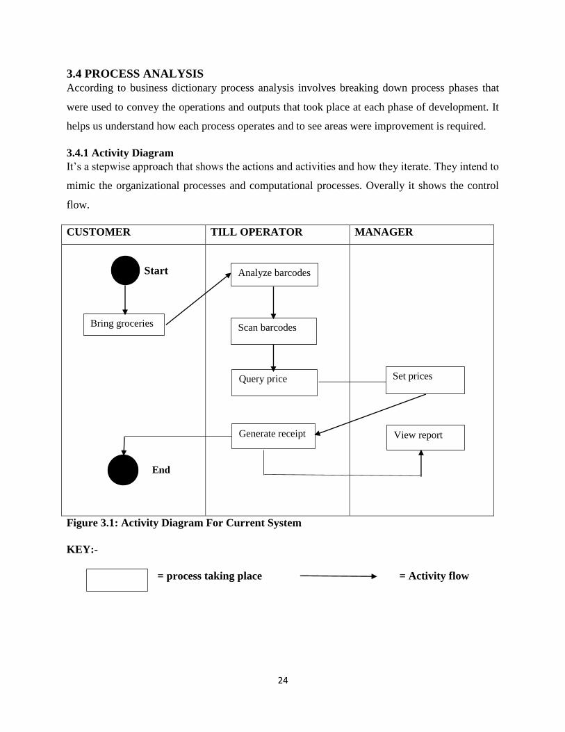
3.4 PROCESS ANALYSIS
According to business dictionary process analysis involves breaking down process phases that
were used to convey the operations and outputs that took place at each phase of development. It
helps us understand how each process operates and to see areas were improvement is required.
3.4.1 Activity Diagram
It‟s a stepwise approach that shows the actions and activities and how they iterate. They intend to
mimic the organizational processes and computational processes. Overally it shows the control
flow.
CUSTOMER TILL OPERATOR MANAGER
Start
Figure 3.1: Activity Diagram For Current System
KEY:-
= process taking place = Activity flow
Bring groceries
Analyze barcodes
Scan barcodes
Query price
Generate receipt
Set prices
View report
End

25
3.5 DATA ANALYSIS
Involves data evaluation through the use of logical reasoning and analyzing the data provided
and come up with a solution. Data collected about the organization should be usable and valuable
(Longnecker, 2008). Data analysis was represented in the form of a data flow diagram.
3.5.1 Context Diagram
A context diagram is a diagrammatic representation that shows the system as a higher level
process. It also shows the relationship between entities and the system. Below is the current
systems context diagram:-
Figure 3.2: Context Diagram For Current System
KEY:-
= Entity =System =Data flow

26
3.5.2 Data Flow Diagram For Current System
A data flow diagram is a representation in diagrammatic form that shows how information flows
and is exchanged in a system. Is describes the processes involved at each phase of system
performance (Dennis etal, 2014). It starts from the entity inputs, then processes the data attained
and is eventually given as output and stored in data stores.
2
Select
groceries
4
Query
commodity
price
5
Make payment
3
Scan bar codes
CUSTOMER
TILL OPERATOR
Purchases
Prices
Scanned bars
Grocery prices
Money
Payment details
Bars
Code details
1
Set prices
SALES MANAGER Price

27
Figure 3.3: DFD For Current System
KEY:-
= Entity = Process =data flow = data store
3.6 WEAKNESSES OF THE CURRENT SYSTEM
Current system is conventional in the sense that:-
Customer has to pick up items and join the queue in order to pay for items.
System has slow processing capabilities in the event of many customers entering the shop
to purchase.
More time is taken in the process of punching figures on the till.
High stationary casts since there is need to print receipts.
Need to employ and train employees that will work as till operators.
Prone to errors in the event of failure to instantly update the database or if the till operator
punches wrong bar codes.
There is repetition of processes. Hence reducing employee morale.
3.6.1 Strengths Of The Current System
Reports on daily activities is clearly accessible.
The system has strong authenticity in all its operations.
6
Calculate
change
7
Generate
receipt Receipts
Receipt Receipt details
Calculation details
Details
8
View reports
Report
s Reports
Sales report

28
Current system also shows the till operator who served customers at the current date and
time hence making it easy to see activities done by each employee and it also becomes
easier to see any errors done.
3.7 EVALUATION OF ALTERNATIVES
A number of alternatives were looked at as a means to identify the best that would minimize the
problems identified at Pick n Pay. After gathering all the information the researcher presents the
report and a meeting is held with the management who will there after decide on whether to
outsource, improve or internally develop the system.
3.7.1 Outsourcing
Braggs (2006) states that outsourcing is a situation when a company decides to purchase services
from an outside source instead of using personal resources and facilities to perform the same
work. It involves weighing the opportunity cost of outsourcing services.
3.7.1.1 Benefits Of Outsourcing
It can be a cost saving strategy if implemented properly.
It helps them focus on other core competence activities rather than project development.
It increases flexibility since other ideas and new technologies are outsourced.
If the services are being provided by a professional company, it can lead to a higher
competitive advantage.
3.7.1.2 Disadvantages Of Outsourcing
There is poor quality control since almost all activities are controlled by the outsourced
company.
Project can be expensive and difficult to maintain in the long run.
Organizational confidentially is exposed since the developing company will have access
to some of the company information that will help them build the project.
Outsourced company can teach competitors about the company system hence minimizing
the firm‟s competitive advantage.
29
3.7.2 Improving The Current System
Pick n Pay might decide to upgrade the existing system with an attempt to improve services.
Upgrade can be in the form of increasing employees or upgrade of computer hardware and
software so as to reduce the lagging time that will lead to long hectic queues.
3.7.2.1 Advantages Of Improving The Current System
It can be seen as a cheaper option since maintenance and upgrade is done by the internal
stuff.
In the event f just a hardware and software upgrade, there will be no need to increase
personnel.
No need for training expenses since there will be not much difference between current
system and upgraded system.
3.7.2.2 Disadvantages Of Improving The Current System
Current system is of a low processing speed therefore, even if upgraded there might be no
change at all.
The complexity nature of the current system may lead to complications in upgrading.
Upgrade can also affect working hours hence may have an effect on sales.
3.7.3 In-House Development
Involves activities being operated internally in an organization instead of seeking assistance from
an outside company (Seffah etal, 2006).
3.7.3.1 Advantages Of In-House Development
It is important for speedy projects since internal personnel will be working towards a
stated target and time frame.
No need to cater for training costs of teaching employees on house to make use and
maintain the system since all is done internally.
It is important in retaining Pick n Pay‟s competitive advantage since it is hard to do so
when a firm has been approached to develop the system and knows all the company
operations and actions.
Helps increase organizational innovation, image and company operations.
Total control of the system is assured.
3.7.3.2 Disadvantages Of In-House Development
Internal developers may lack standard expertise to develop a standard system.

30
In-house development requires a strong budget from both the development phase and
maintenance of the system.
Start-up costs can be hard to manage.
ALTERNATIVE COST SUMMARY (US$)
Outsourcing 15 000
Improving current system 10 200
In-house development 7 500
Table 10: Alternative Analysis Table
3.7.4 Conclusion Of Analysis
Pick n Pay saw it of a greater advantage to opt for in-house development since the cost is lesser
than the other alternatives at the same time, benefits of in-house development have a hope of
making them have a greater competitive advantage than its competitors in the future.
3.8 REQUIREMENTS ANALYSIS
Requirements analysis is more like a contract between the developer and the client. It assesses
wat the system should fulfill basing on current problems and future plans in relation to customer
requirements. System functionality should fulfill organizational operations in every way.
3.8.1 Functional Requirements
Functional requirements look at 4 aspects:-
1. Functions that are expected to be supported by the proposed system.
2. Inputs that will be put into the system.
3. Outputs or feedback from the system.
4. Data to be managed by the system in its operation.
The Pick n Pay customer self-service mobile application will have the following functional
requirements:-
System security is a major concern, unauthorized users should not have access to the
database and is operations.

31
Report generation should be fast, efficient and accurate.
Multiple users should be able to access the system concurrently at the same time.
It should be able to know a specific area of concern each time the database is queried.
Virtual receipt should be quickly generated as soon as payment has been done.
Automatic updates should occur each time a customer purchases or deposits money I his
account.
System should have user access levels.
3.8.1.1 The Use Of Case Diagram
According to Kulak (2012) a use case diagram is a representation or methodology that shows the
relationships between system entities and their duties. It shows how a user interacts with the
system to achieve a certain goal.
Provide details
Give funds
Register for application
Create account
Create card
Register card
Scan barcode and make
payment
ADMINISTRATOR
CUSTOMER
Set prices
SALES MANAGER

32
3.8.2 Non-Functional Requirements
Non-functional requirements look at how the proposed system will support the functional
requirements in performance, security, reliability and usability (Chung, 2012). Some of these
requirements are shown below:-
System should have a facility for backup in the event of data loss.
It should be understandable to the user that s, it should be user friendly.
It should have a facility for error handling, which is it should have error recovery
platform.
System security should be looked at therefore the use of passwords for every user is
important.
It is supposed to have a quick response time.
It should be reliable, that is doing the correct things at the right time each and every time.
It should be usable to every individual.
It must be easy to maintain and shouldn‟t be vague in its use.
3.8.2.1 Constraints
Time: project completion within the stipulated time might be difficult due to some constraints
that might come on the way.
Costs: It might be difficult for Pick n Pay to face the possible costs for a standard system
development.
Adequate funds: Project costs and company budget might conflict.
3.9 CONCLUSION
Researcher has described the current system and considered the alternatives, activities and
functionality of the system. It has been concluded that there is need to develop the new system
Get feedback
View reports
Figure 3.4: Use Case Diagram For The Proposed System
33
therefore the next chapter will dwell much in designing the proposed system and giving a brief
description of its functionality.
CHAPTER FOUR: SYSTEM DESIGN
4.1 INTRODUCTION
This chapter will involve defining and analyzing the system‟s architecture, modules, components
and system data. An analysis was made in the previous chapter and after analyzing the loopholes
of the current system then there is need to move on to the design phase. Basing on the system
requirements analyzed in the previous chapter, the system will be developed to meet user
requirements and at the same time solving problems analyzed. This chapter will look at the
systems architecture, database design, interface design, program design, physical design and
finally the test design of the proposed system.
4.2 PROPOSED SYSTEMS DESIGN
According to Flynn (2011) system design is that process of defining the architecture,
components, interfaces, modules and system data. Major concern is to meet user requirements
and organizational goals through a well-functioning system. An impressive functioning system
should have the following characteristics:-
Effective – this involves developing a system that is error free and does not affect the
organizational working and processing environment. At the same time, system should be
a problem solver and meeting all the company objectives in its day to day running of the
business.

34
Reliable – system should be able to provide information and reports in a timely manner
whenever needed. It should be a solution to the current system‟s problems and should not
delay decision making of the top management.
Efficient – system should provide correct, required and accurate answers or solutions to a
problem at a certain given period of time.
Secure – organizational confidentiality should be a key element. Therefore system should
have access levels in system usage to avoid licking of important information that will
hinder system performance.
Maintainable – operation of system should not be vague. It should be effective and
efficient and should give room for system upgrades whenever required.
4.2.1 Major Systems Functionalities
This will show the major areas of concern that will lead to the full functionality of the system.
These are described below:-
Products module – this is the platform to which product bar codes are added in store and
also updates of outdated or obsolete products are recorded. It also allows employee to
view the available products in store.
Customers’ module – this is where new customers are added and where they deposit
their moneys and a virtual card created for them to use for their shopping. Available
customers recorded are also visible on this platform.
Administrator module – is for the creating or deleting of users, that is administrators or
sales managers that have the permission to access the system.
Sales manager (or representative) module – adds new products and customers into the
system and makes customer deposit entries.
Sales report module – report on sales for the day and a given period of time is shown on
this platform.
Account details – shows accounts deposited by a specific user and balances for each user
soon after purchasing products.
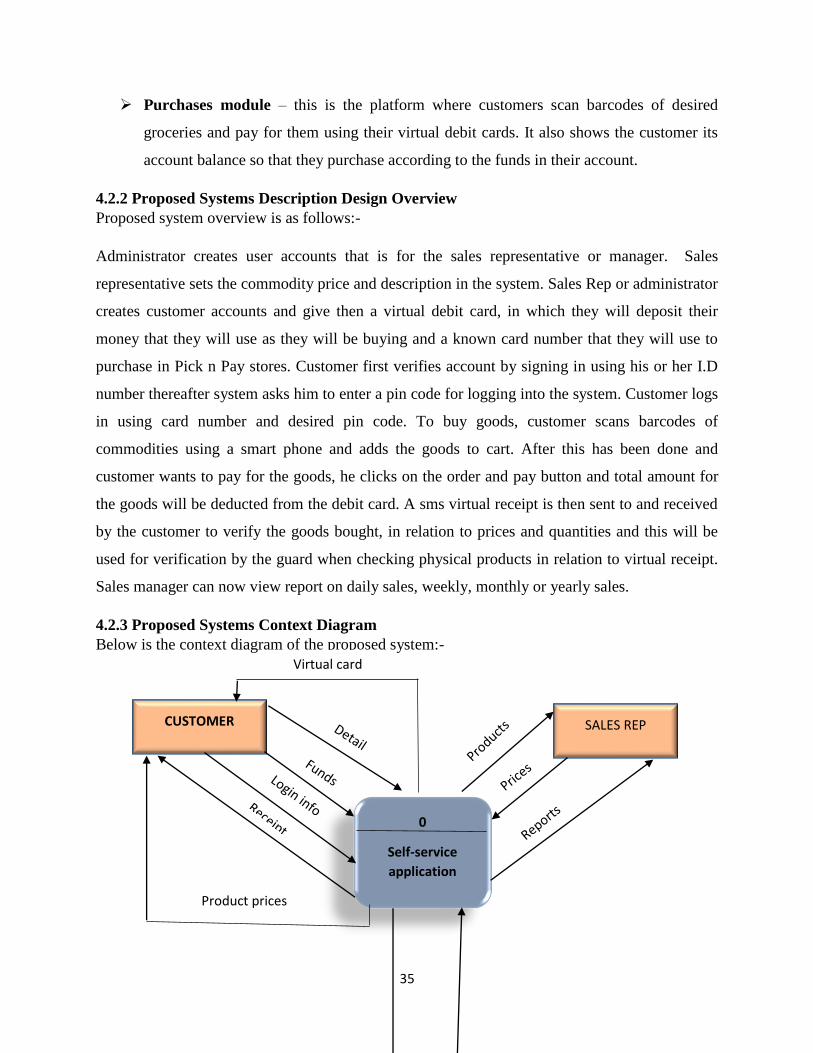
35
Purchases module – this is the platform where customers scan barcodes of desired
groceries and pay for them using their virtual debit cards. It also shows the customer its
account balance so that they purchase according to the funds in their account.
4.2.2 Proposed Systems Description Design Overview
Proposed system overview is as follows:-
Administrator creates user accounts that is for the sales representative or manager. Sales
representative sets the commodity price and description in the system. Sales Rep or administrator
creates customer accounts and give then a virtual debit card, in which they will deposit their
money that they will use as they will be buying and a known card number that they will use to
purchase in Pick n Pay stores. Customer first verifies account by signing in using his or her I.D
number thereafter system asks him to enter a pin code for logging into the system. Customer logs
in using card number and desired pin code. To buy goods, customer scans barcodes of
commodities using a smart phone and adds the goods to cart. After this has been done and
customer wants to pay for the goods, he clicks on the order and pay button and total amount for
the goods will be deducted from the debit card. A sms virtual receipt is then sent to and received
by the customer to verify the goods bought, in relation to prices and quantities and this will be
used for verification by the guard when checking physical products in relation to virtual receipt.
Sales manager can now view report on daily sales, weekly, monthly or yearly sales.
4.2.3 Proposed Systems Context Diagram
Below is the context diagram of the proposed system:-
SALES REP CUSTOMER
0
Self-service
application
Virtual card
Product prices

36
Figure 4.1: Context Diagram
4.2.4 Proposed Systems Dataflow Diagram
Below is the dataflow diagram of the proposed system:-
ADMINISTRATOR
Cu
sto
mer
det
ails
Car
d d
etai
l
1
SET PRICES
3
REGISTER
APPLICATION
2
RECEIVE
FUNDS AND
DETAILS
4
CREATE
ACCOUNT
5
CREATE
CARD
6
REGISTER
CARD
7
SCAN
CUSTOMER
ADMINISTRATOR
Prices
Funds
Details
Details
Debit card
Card information
Card details
Details
SALES REP
CENTRALIZED
COMPUTER
DBMS

37
KEY
10
GENERATE
RECEIPT
Digital receipt
Card details
11
GENERATE
REPORT
SALES REP Reports
Figure 4.2: Dataflow Diagram

38
Centralized database
4.3 ARCHITECTURAL DIAGRAM
System architecture describes the behavior structure and relation between system components.it
is a diagrammatic representation of the system and how it will interact with its entities, hardware
and software infrastructure. Major thrust is on minimizing problems that might hinder system
performance. It will also look at the hardware platform to which the system will run and the
various software‟s that will make the system workable. Inputs and outputs on each link and flow
of data will be looked at. System will be both windows based and application based.
Below is a general elucidation of the various architectures to be included for system to be
efficient:-
Mobile device – device will act as a router through the use of wifi hotspot. Customer will be
able to purchase goods using their mobile device.
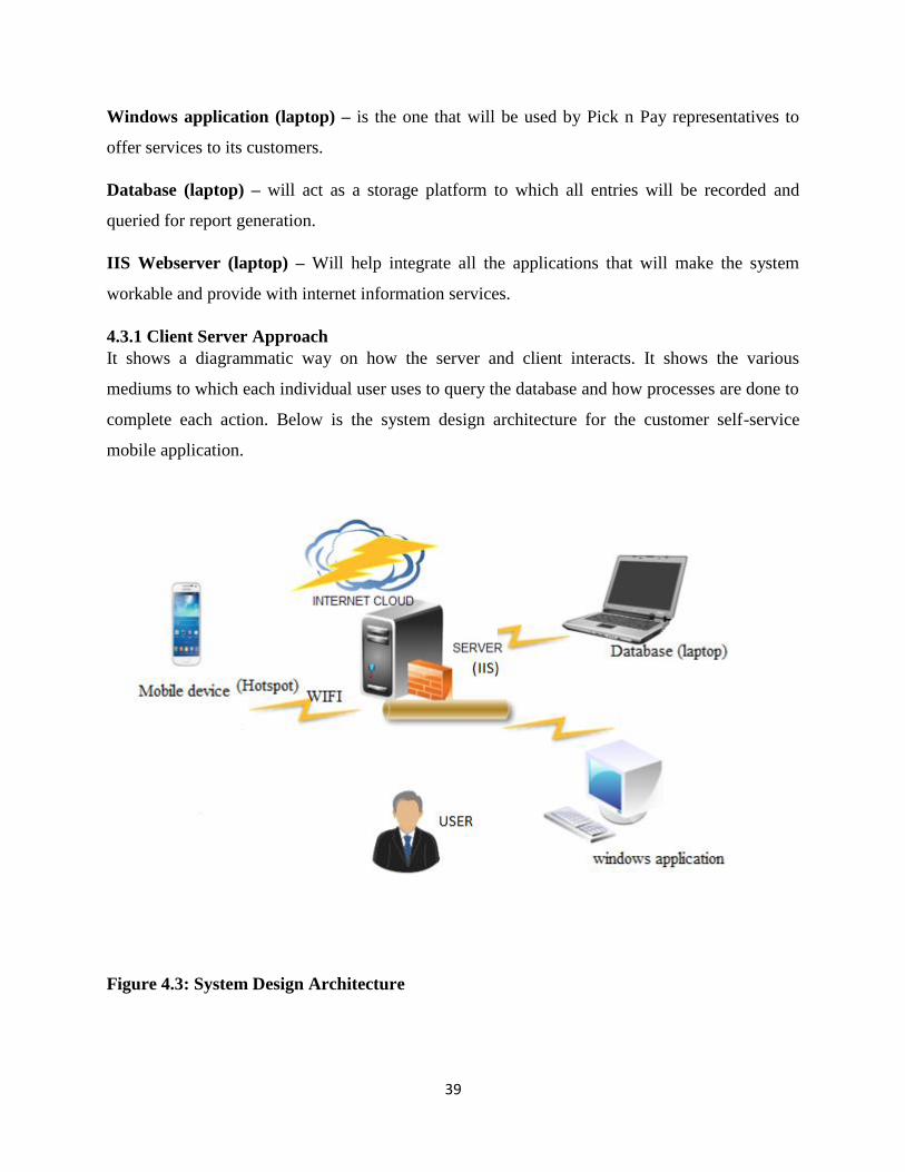
39
Windows application (laptop) – is the one that will be used by Pick n Pay representatives to
offer services to its customers.
Database (laptop) – will act as a storage platform to which all entries will be recorded and
queried for report generation.
IIS Webserver (laptop) – Will help integrate all the applications that will make the system
workable and provide with internet information services.
4.3.1 Client Server Approach
It shows a diagrammatic way on how the server and client interacts. It shows the various
mediums to which each individual user uses to query the database and how processes are done to
complete each action. Below is the system design architecture for the customer self-service
mobile application.
Figure 4.3: System Design Architecture

40
4.4 PHYSICAL DESIGN
Here, the technical environment to which the proposed system will be implemented is described
and the ways in which networks will be linked is defined. System will be controlled and
centralized in the administrator‟s office and the sales representatives will access system services
via the LAN. This will increase security levels and improve system monitoring.
Figure 4.4: System Database Architecture
4.5 DATABASE DESIGN
It is the process of coming up with a database data model. In includes entity relationships,
physical design that is, keys, columns and table and CAD tools used for the data. Success of the
proposed system will depend on meeting all the user requirements and its capability of solving
all the identified problems. Database should promote consistency, integrity and minimization of
redundancy.
4.5.1 Database Design Architecture
The architecture‟s main focus is on designing, developing and maintaining of programs that are
responsible for storing and organizing required information for the organization. Software is
developed and implemented by the architecture with the main reason of meeting user needs.
Architecture will show the various entities that will directly and indirectly link to the database
schema. Below is a diagrammatic design of the schema:-
Server
Logins
Requests
Reports
Payments
Decisions
Server side Client side
Database

41
Figure 4.5: Database Schema
External view
This is the external view of the database schema also known as the highest level. It provides an
interactive interface for the user that will help them manipulate required data at any given point
in time. Some parts of the database and implementation details are hidden from the users and
only information relevant to them can be accessed. This is for the sake of enhancing security to
the company database.
42
Conceptual level
This shows how the data in the database is related and how this data is stored in schema.
Database design for the community is defined at this level. Main focus in on entity description,
relationship between entities, user operation, data types and the rules or constraints that govern
the schema.
Physical level
It‟s mainly responsible for storing data in different forms, which can only be readable by the
database management system.
Database
This is the actual database or repository to which all the information will be stored and retrieved
from.
4.5.2 Data Modeling
Is the process of creating a data model and having the knowledge of how the data will relate. In
involves analyzing and defining the required data that is to be stored in the database. This data
must match with the organization‟s information system. The entity relationship diagram and the
enhanced entity relationship diagram will help elucidate the concept of data modelling.
4.5.2.1 Entity Relationship Diagram
It is a modelling technique that diagrammatically shows the relationship between entities. Its
elements include attributes relationships and entities. To create an entity relationship diagram
one has to:-
Identify and define entities
Determine the interaction between entities
Determine the cardinality of the relationships between these entities
Finally create the diagram
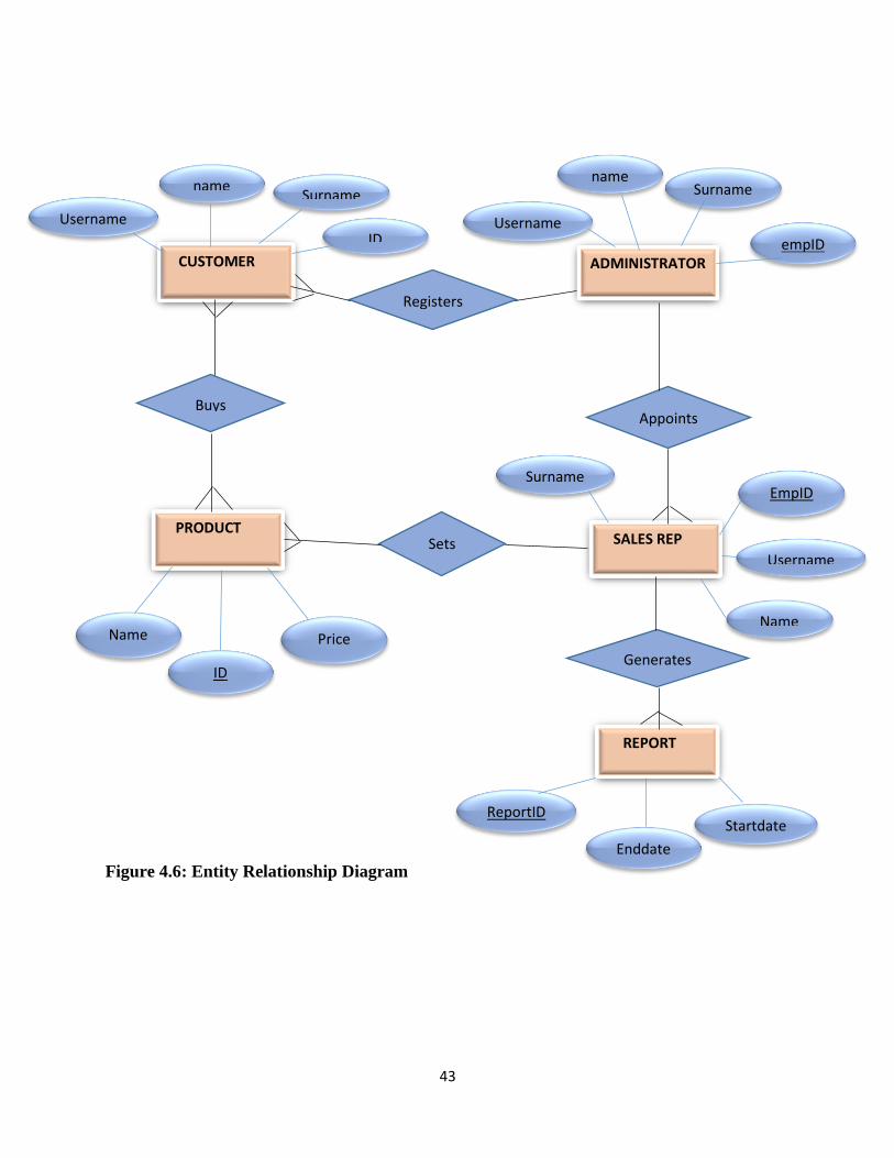
43
Figure 4.6: Entity Relationship Diagram
CUSTOMER
SALES REP
ADMINISTRATOR
REPORT
PRODUCT
Username ID
name Surname
Name
ID
Price
Surname
empID
name
Username
Registers
Buys Appoints
Sets
Generates
Surname
Name
EmpID
Username
ReportID
Enddate
Startdate

44
KEY
4.5.2.2 Tables Of The Systems Database
Client registration
TITLE LENGTH DATATYPE
Name 30 String
National_ID 11 Varchar
Mobile_no 10 Integer
Card_no 4 Integer
Deposit_amount 6 Integer
Table 11: Client Registration

45
Adding new Products
TITLE LENGTH DATATYPE
Bar_code 13 Integer
Item_name 40 Varchar
Item_cost_unit 6 Double
Description 40 Varchar
Table 12: Adding new Products
Create user account details
TITLE LENGTH DATATYPE
Name 30 String
Username 30 String
Password 10 Varchar
Access_Type 10 String
Table 13: User Account Details
4.5.2.3 Enhanced Entity Relationship Diagram
An enhanced entity relationship shows the subtype and super type relationships between entities.
Below is the enhanced ERD for the system database.

46
Figure 4.7: Enhanced Entity Relationship Diagram
CUSTOMER
ADMINISTRATOR
REPORT
PRODUCT
STAFF
SALES REP
d
Name Price
ID
Surname ID
name
Surname Name
empID Username
Registers Sets
Buys
Username
Startdate
Enddate
ReportID

47
KEY
4.6 PROGRAM DESIGN
Program design is a modular that assists various entities directly involved to the to make sure
that it is performing according to the specified requirements when implemented.
4.6.1 Package Diagram
A package diagram shows how the various packages that make up a model relate to each other. It
breaks down complex projects into simplified modules through the use of diagrammatic
representation.
KEY FOR DIAGRAM BELOW

48
Figure 4.8: Package Diagram
Presentation layer
User Interface
Customer Registration
Business Operations Layer
Service Processing
Manager
viewing reports
Product
purchasing
Virtual card
activation
Data layer
Transactions
storage
Storage of
report files

49
4.6.2 Class Diagram
Figure 4.9: Class Diagram
Customer
ID_varchar <PK>
Surname_string
Name_string
Product
ID_varchar <PK>
Price_int
Name_string
Report
ReportID_varchar <PK>
Startdate_varchar
Enddate_varchar
Sales Rep
EmpID_varchar <PK>
Surname_string
Name_string
Username_string
Administrator
Emp_ID_varchar <PK>
Surname_string
Username_string
Name_string
1…* Registers
1…* Sets
Appoints
1…*
Generates
1…*
1…*
Buys
1…*

50
4.6.3 Sequence Diagram
According to Daniels (2003) sequence diagrams are interactive diagrams that deal with objects
that work hand in hand. They focus on how given tasks interact over time to meet a given target.
Below is a sequence diagram for Pick n Pay stores.
CUSTOMER ADMINISTRATOR SALES MANAGER
Customer details
Creates virtual card
Request for service
Service granted
Feedback
Login information
Reports
Manages
Figure 4.10: Sequence Diagram
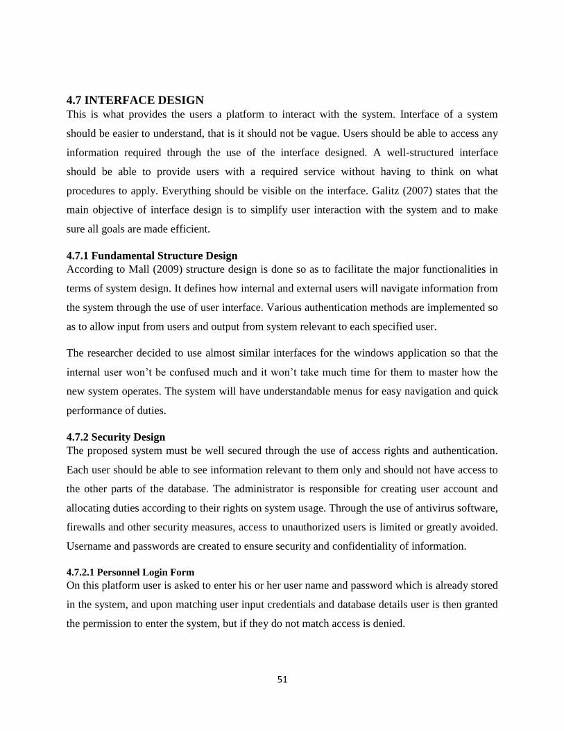
51
4.7 INTERFACE DESIGN
This is what provides the users a platform to interact with the system. Interface of a system
should be easier to understand, that is it should not be vague. Users should be able to access any
information required through the use of the interface designed. A well-structured interface
should be able to provide users with a required service without having to think on what
procedures to apply. Everything should be visible on the interface. Galitz (2007) states that the
main objective of interface design is to simplify user interaction with the system and to make
sure all goals are made efficient.
4.7.1 Fundamental Structure Design
According to Mall (2009) structure design is done so as to facilitate the major functionalities in
terms of system design. It defines how internal and external users will navigate information from
the system through the use of user interface. Various authentication methods are implemented so
as to allow input from users and output from system relevant to each specified user.
The researcher decided to use almost similar interfaces for the windows application so that the
internal user won‟t be confused much and it won‟t take much time for them to master how the
new system operates. The system will have understandable menus for easy navigation and quick
performance of duties.
4.7.2 Security Design
The proposed system must be well secured through the use of access rights and authentication.
Each user should be able to see information relevant to them only and should not have access to
the other parts of the database. The administrator is responsible for creating user account and
allocating duties according to their rights on system usage. Through the use of antivirus software,
firewalls and other security measures, access to unauthorized users is limited or greatly avoided.
Username and passwords are created to ensure security and confidentiality of information.
4.7.2.1 Personnel Login Form
On this platform user is asked to enter his or her user name and password which is already stored
in the system, and upon matching user input credentials and database details user is then granted
the permission to enter the system, but if they do not match access is denied.
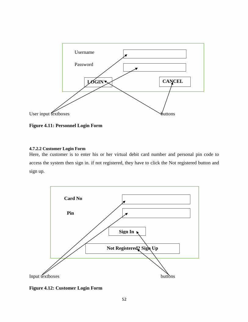
52
User input textboxes buttons
Figure 4.11: Personnel Login Form
4.7.2.2 Customer Login Form
Here, the customer is to enter his or her virtual debit card number and personal pin code to
access the system then sign in. if not registered, they have to click the Not registered button and
sign up.
Input textboxes buttons
Figure 4.12: Customer Login Form
Username
Password
LOGIN CANCEL
Card No
Pin
Sign In
Not Registered? Sign Up

53
4.7.2.3 Creating User Account Form
On this platform the windows application user account is created as either administrator or a
sales representative.
Figure 4.13: Creating User account Form
4.7.3 Main Menu Form
Operations will occur in a procedural way such that, when a user queries the database or inputs
information, this input will be processed to give output and the output will navigate to the next
form until the service required by the user has been met.
4.7.3.1 Input Design
This forms will accept user input, process and gives out output each time the user queries. Major
entities that will make use of the system are the customer, administrator and the sales
representative. Input forms will be validated so as to provide relevant information from each user
and this will then be processed to assist the users. Text boxes were used to allow text input from
users. Below are various input forms that will be used in the design of the proposed system.
4.7.3.1.1 Customer Registration Form
This form will be used to register customers for the mobile application to function in the Pick n
Pay stores.
Name
Username
Password
Confirm Password
Access Type
SAVE EXIT

54
Figure 4.14: Customer Registration Form
4.7.3.1.2 Adding New Products Form
This form is mainly for adding new products in stock showing their description and prices. This
information will then appear each time a customer scans barcode of a certain product.
Figure 4.15: Adding New Product
Name
National ID
Mobile Number +263
Card Number
Deposit $
SAVE CLEAR
Bar_Code
Item_Name
Item_Cost_Unit $
Description
SAVE CLEAR

55
4.7.3.2 Output Design
These will show how the processed information will appear after being viewed by various
entities normally in a summarized way. This information is used for decision making or
information planning. Below are output forms that will comprise the proposed system.
4.7.3.2.1 Products Report
This report will show a list of all the products in stock.
REPORT
Product_ID Barcode Item_Name Cost Item_Description
Figure 4.16: Products Report
4.7.3.2.2 Customer List
This report will show a list of all customers that have registered for the mobile application
system.
REPORT
ID Cust_Name Cust_ID Card_No Cust_Mobile
Figure 4.17: Customer List Report
4.7.3.2.3 Account Balance
This report will show the list of balances of accounts for all customers.
REPORT
Cust_Name Cust_ID Card_No Balance

56
Figure 4.18: Account Balance Report
4.7.3.2.4 Sales Journal
The sales journal report will reveal all the product purchased by customers, the transaction i.d,
barcode of product, cost, customer card number and date of transaction are shown.
REPORT
Transaction_ID Barcode Cost Card_No Date_Time
Figure 4.19: Sales Report
4.7.3.2.5 Order List
The order list report is visible to the customer were by a description of all products scanned and
added to cart are summarized and listed and eventually customer decides whether to pay them or
delete products from cart.
Figure 4.20: Customer Order List
Item name
Quantity
Cost
Status
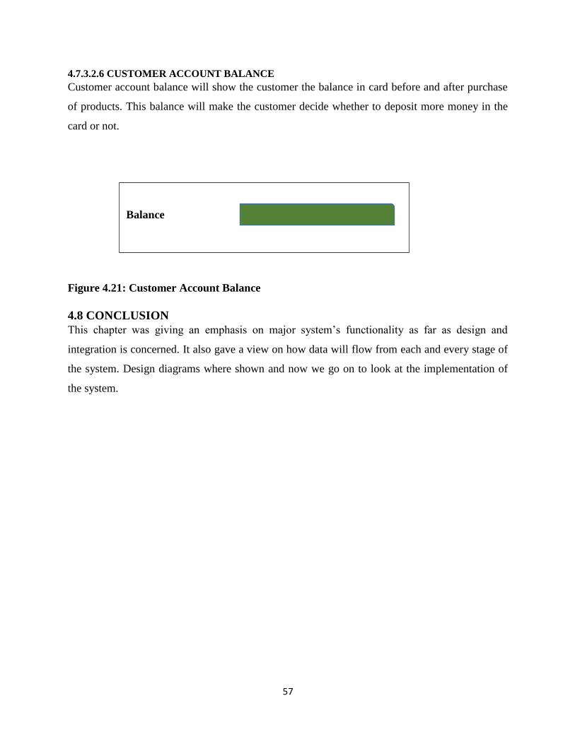
57
4.7.3.2.6 CUSTOMER ACCOUNT BALANCE
Customer account balance will show the customer the balance in card before and after purchase
of products. This balance will make the customer decide whether to deposit more money in the
card or not.
Figure 4.21: Customer Account Balance
4.8 CONCLUSION
This chapter was giving an emphasis on major system‟s functionality as far as design and
integration is concerned. It also gave a view on how data will flow from each and every stage of
the system. Design diagrams where shown and now we go on to look at the implementation of
the system.
Balance

58
CHAPTER FIVE: IMPLEMENTATION PHASE
5.1 INTRODUCTION
The chapter shows the processes carried out in implementing the proposed system. It makes sure
that the system is delivered to the user as per requirements. Ibach (2001) defines system
implementation as constructing the new system and delivering the system into production.
System modules are analyzed and tests are carried out to check for efficiency and effectiveness.
Error handling is also done and loopholes are eventually fixed.
5.2 CODING
Kerig (2004) says coding is the process of defining statements and scripts encoded to come up
with a workable and running program. This code which is a form of machine language,
understood by the computer is then converted to human language to provide the required by the
system users. Functionalities and system operations are determined by the code implemented.
5.3 TESTING
Beizer (2007) defines system testing as performing sequential tests to see the functionality and
identify problems of the system. These tests makes it easier to see the possible errors that might
hinder the system and they find ways to curb these problems so that it won‟t affect them in the
future running of the system. A number of stages are involved in system testing.

59
Figure 5.1: Testing Stages
5.3.1 Unit Testing
According to Saleh (2009) unit testing is a process were by the testable units of an application
are scrutinized independently to check if they operate properly. Its main aim is to verify the
functionality of a selected code area or system component. Two types of testing strategies were
used by the researcher that is black box testing and white box testing
5.3.1.1 Black box Testing
Gross (2006) defines black box testing as a testing software method that looks more into the
functionality of the system and leaves out the internal structure or operations of the application.
This method of testing is applicable any level of the software that is, acceptance, system,
integration and unit testing. Main focus is on reaching a specified goal not on the input and how
the system generated the results.

60
Figure5.2: Black Box Testing
5.3.1.1.1 Advantages Of Black Box Testing
Due to the presence of complete functional requirement, design is not difficult.
Tester does not need to have detail on the internal knowledge about the system to be
tested.
It is simple to use since focus is on invalid and valid inputs and to make sure that there is
output generation.
No need for technical expertise when doing black box testing.
5.3.1.1.2 Disadvantages Of Black Box Testing
No guarantee that every line of code has been tested.
Result over estimation normally occurs.
Slow progress since it is difficult to identify all the listed inputs due to limited testing
time.
5.3.1.2 White Box Testing
Desikan (2006) states that white box testing tests the internal structure of the application. Main
focus is on innermost details of the application. It is also known as glass box testing, clear box
CUSTOMER
SELF-SERVICE
MOBILE
APPLICATION
Black Box Test

61
testing, structural testing or transparent box testing. Tester needs much expertise to interact with
all the components that were used to develop the application and then give results of the test.
Figure 5.3: White Box Testing
5.3.1.2.1 Advantages Of White Box Testing
White box testing helps in code optimization.
It helps remove unnecessary lines of code that can bring defects in program functionality.
Detection of errors is done earlier before full implementation of the application.
5.3.1.2.2 Disadvantages Of White Box Testing
It is an expensive method of testing since there is need for a skilled tester.
Not every line of code will be analyzed hence can lead to failure of the application
Does not take into account errors of omission.
5.3.2 Module Testing
Saleh (2013) postulates that module testing involves the test and analysis of a list of integrated
tests that are extended from the previously discussed unit test. After the developer has written
code, the tester comes up with a list of areas that will be checked on defects and interface
interaction.
62
5.3.3 Subsystem Testing
Subsystem testing focuses on testing the application programming interfaces between
Subsystems. The test involves testing modules that are unified in a specified subsystem. Pick n
Pay customer self-service application was tested as an independent sub system with the central
host not linked to the database.
5.3.4 System Testing
All modules are integrated so as to come with the entire system and is then tested so as to see if it
performs tasks as it should be and if it solves the loopholes discovered in the problem definition.
System should operate according to the defined project scope development. Pick n Pay
configured the system on its central network with the main objective of analyzing if it is meeting
the required functionalities as desired. System was able to perform all that was lacking in the
current system‟s operation.
5.3.5 Acceptance Testing
After defects have been corrected on the system, system is eventually taken to the users for
acceptance testing. Acceptance testing is done by users, stakeholders and customers to see if the
system meets their requirements. The major aim of acceptance testing is to gain confidence on
system performance. System is also tested to see if it meets business process and to also check its
efficiency and quality. Acceptance testing includes Alpha testing and Beta testing.
5.3.5.1 Alpha Testing
The test is done at the site of the developer. Problems stated by the users are noted. Craig (2006)
states that alpha testing is normally done when the development is about to complete and it is
done by a group independent of the development team for example quality assurance engineers.
Changes can be done as a result of this test. This test is done before full implementation to the
general public. Alpha testing at Pick n Pay was done in two phases, the first phase involves in-
house developers testing for bugs using debugger software and the second phase involves giving
the software quality assurance staff for testing in an almost similar environment to the one that
the system is supposed to be rum. The test was done at Pick n Pay and changes where done to
some interfaces font and color of pages.

63
5.3.5.2 Beta Testing
According to Pardo (1992) Beta testing is also known as field testing and is implemented on
customer site. System is sent to users and they install it to use under real world scenario. It is the
phase done secondly (pre-release testing) after alpha testing so as to try out the product.
Objective of beta testing is to give the application to actual customers so as to gather issues of
system performance from user perspective.
5.3.6 Testing Strategies
These are strategies used by the researcher so as to measure the efficiency and effectiveness of
the system proposed. In practicing these strategies errors were identified and eventually
corrected. Below are the strategies that were used to test the proposed system performance:
5.3.6.1 Validation
Validation are the actions that check the compliance of the system performance. The system is
evaluated to see if it was developed right. For example if we enter string characters in a field that
requires numeric characters the system should pop up an error message, and if required input is
entered, access should be granted as well.
5.3.6.1.1 Log In Validation
On this platform users are prompted to enter credentials for logging in and if correct details are
entered, a user is given access to their authorized window were information specific to them is
acquired. Users who are unauthorized won‟t have access since system will show an error
message requiring authenticity to the user. The figure below shows the system login page for the
customers and for the windows application internal users:-

64
Figure 5.4: Customer Login
Below shows the internal users login window:-
Figure 5.5: Internal Users Login
Below shows the pop out window when incorrect credentials are entered.

65
Figure 5.6: User Login Fails
5.3.6.2 User Input Validation
This refers to how correct user information is the moment he or she enters credentials.
Credentials should be entered in the text boxes provided.
Figure 5.7: Customer Registration
This shows the adding of a new user to the system and the required details and formats in each
field.

66
Figure 5.8: Sales Rep Registration
Figure below shows the pop up message when login has been successful.
Figure 5.9: Success Login Pop Up Message
5.3.6.3 Test Cases
Pusuluri (2006) states that test cases involve testing for the workability of the system be it system
validation and system features. This is done by the system developer before fully implementing
the system to the organization. The practice is done by the system developer and the features are
determining factor on whether the system is working perfectly or not and is it meeting the stated
requirements.
Test Case One: User Login

67
User or customer must know his or her credentials that is username and password. If credentials
are correct users should be granted access, if they are incorrect access to the system resources
should be denied.
Screen Shot Admin Login Page
Figure 5.10: Test Case One
Test Case Two: Register Customer
Customer should be registered with personal details that is name, phone number, ID number and
amount to be debited in the virtual debit card. These fields are validated to accept specified input
characters. As shown in the figure below, ID should be in the format ## - ###### - D -## that is
alphanumeric characters and mobile number field cannot be left null.

68
Figure 5.11: Test Case Two
Test Case Three: Adding Products
Products are added by specifying the product bar code, name price and description. This will
make it easier for the customer to have full knowledge of the required products. If correct data
for the product has been added, the window as shown in the figure below appears.
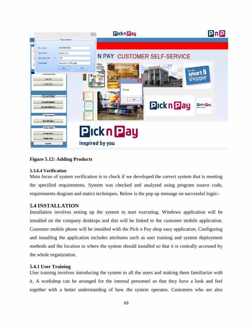
69
Figure 5.12: Adding Products
5.3.6.4 Verification
Main focus of system verification is to check if we developed the correct system that is meeting
the specified requirements. System was checked and analyzed using program source code,
requirements diagram and statics techniques. Below is the pop up message on successful login:-
5.4 INSTALLATION
Installation involves setting up the system to start executing. Windows application will be
installed on the company desktops and this will be linked to the customer mobile application.
Customer mobile phone will be installed with the Pick n Pay shop easy application. Configuring
and installing the application includes attributes such as user training and system deployment
methods and the location to where the system should installed so that it is centrally accessed by
the whole organization.
5.4.1 User Training
User training involves introducing the system to all the users and making them familiarize with
it. A workshop can be arranged for the internal personnel so that they have a look and feel
together with a better understanding of how the system operates. Customers who are also

70
interested in using the mobile application can also be trained on how to use it and the application
can be installed on their smart phones. This will help reduce confusion between users.
5.4.2 Operation Environment
This is the environment to which the system will operate in and the required resources for it to
efficiently work. Major required components for the system to run are listed below:-
Android platform
Control systems
Networking equipment
Software configurations
Hardware infrastructure
5.5 CONVERSION
Pardo (1992) states that this is the process were by the system is implemented after all the
processes of verification, validation and testing have taken place. It involves switching from the
previous way of operation to the new mobile system. This is the last step taken by Pick n Pay for
the customer self-service application to be fully in use.
5.5.1 System Change Over
System changeover involves smoothly shifting from one way of business operations to another
and mitigating possible disruptions in organizational activities during the changeover process.
System changeover can take place in four ways that is, direct changeover, pilot, parallel and
phased changeover. Changeover strategy will depend on what the organization decides after
weighing the overall merits and demerits of each strategy.
5.5.1.1 Direct Change Over
This involves the total discarding of the previous system in operation and fully implementing the
newly developed system therefore there will be a direct shift in operation. This strategy is the
fastest to implement at the same time it has so much risk to organizational operation in the event
that the new implemented system fails.
5.5.1.1.1 Merits Of Direct Change Over
It has a clear way of implementation since it is just direct.
No need for interface matching since the old way of operation is totally discarded.
It is a cheaper strategy to implement since main focus is on the new system.

71
There is less time taken in conversation.
5.5.1.1.2 Demerits Of Direct Change Over
Reference to the old way of operation becomes impossible since it would have been fully
discarded.
Unavailability of backup makes the strategy risky to business operation.
Users might be affected if a direct changeover is implemented and will eventually lead to
system denial.
5.5.1.2 Parallel Change Over
This involves the simultaneous running of two system that is the old system and the new system
for a specified period of time. This strategy appears to be the most appropriate because if the new
system happens to fail during its operation, the organization and quickly revert to the old way of
operating.
5.5.1.2.1 Merits Of Parallel Change Over
Minimum risk as compared to direct changeover since both systems will be in operation.
It gives room for comparative analysis on the performance and effectiveness of both
systems.
No data loss due to the availability of backup facility.
Easy reference to information of the old system.
It gives users the platform to compare both systems at the same time familiarizing with it
without disturbing activities.
5.5.1.2.2 Demerits Of Parallel Change Over
It is the most expensive strategy since maintenance is to be done for both systems.
Errors are highly prone since transactions will have to be recorded twice.
It is time consuming and labor intensive especially to personnel.
It leads to increase in salaries and processing delays due to dual recording of data.
5.5.1.3 Pilot Change Over
This involves implementing the system in part of the organization, for example in a certain
department or office. If the system is said to be a success in the pilot site, it is then implemented
in the whole organization. Generally it combines two strategies that is the direct and semi-
parallel changeover strategies.

72
5.5.1.3.1 Merits Of Pilot Change Over
Since focus is to a specified department, it becomes easy to monitor.
Implementation is less expensive since it is done in a specified pilot site only.
In the event of system failure, only the pilot site is affected and not the whole
organization.
System alteration becomes easy since system will be scrutinized at the pilot site during its
operation.
5.5.1.3.2 Demerits Of Pilot Change Over
Both system interfaces needs to be integrated.
Long conversion time.
5.5.1.4 Phased Change Over
Pusuluri (2006) postulate that this involves implementing the system in phases of different
modules of the system. For example in the customer self-service application, implementation can
be done to the sales and purchases then to the human resources. This will lead to the slow
elimination of the old system.
5.5.1.4.1 Merits Of Phased Change Over
Cost is low and errors are isolated
It gives users room to get used to the system at each stage.
In the event of system failure the whole organization is not affected.
5.5.1.4.2 Demerits Of Phased Change Over
System implementation takes long to complete since it is done in phases.
If the system is complex and with many phases it can be very expensive.
5.5.2 Recommended Change Over Strategy
Pick n Pay stores opted for a parallel changeover strategy since the self-service application is a
totally new idea and at the same time not all customers have smart phones to scan barcodes. On
the other hand some customers are elderly people and do not understand the operations of smart
phones. Therefore a parallel changeover will make customers and personnel familiarize with the
new system operation at the same time not reducing general sales of the organization.
5.6 MAINTANANCE
Kelly (2006) postulates that maintenance is the process of making sure that the system is
performing well as expected. The process starts the moment the system is implemented and

73
continues throughout its use in the organization. Changes are made during system operations and
these changes can be upgrades or correcting so as to meet system objectives.
5.6.1 System Review
Involves analyzing how the system operates and how it‟s causing changes to business operation.
Modules of the system are checked for efficiency and productivity. The ICT department is
responsible for maintaining and assessing the system performance. Below is a diagram that
shows the stages in system review.
Figure 5.13: Steps In System Maintenance Activity Diagram
5.6.1.1 Perfective Maintenance
Perfective maintenance ensures that, system interface is usable, processing performance is
improved and alterations that are necessary are done to system features. Main thrust of perfective
maintenance is ensure that, system is maintainable, reliable, has a faster response time and is
reliable. Internal users are the ones that coz a trigger to the need of system perfectiveness
therefore there is need to keep track of ever changing needs of users to ensure system
perfectiveness.
5.6.1.2 Adaptive Maintenance
Adaptive maintenance is the process of changing an information system so that it becomes
flexible to business changing needs or migrating to a unique environment that it will operate in.
Changes
Requests.
Impact
Analysis.
System
Review
Planning.
Change
Implementation
.
System
Release.
Perfective
Maintenance.
Corrective
Maintenance.
Adaptive
Maintenance.

74
Practice of adaptive maintenance increases enhancement of a system for example, additional
system features, or improvement in maintainability and efficiency.
5.6.1.3 Preventive Maintenance
This involves a proactive approach of making changes to the system with an attempt of reducing
possible failures of the system in the future. The system is inspected systematically, errors are
detected then they are corrected to avoid serious system failures in the future.
5.6.1.4 Corrective Maintenance
According to Flynn (2011), corrective maintenance are the changes done to correct defects in
implementation, coding or design. These problems are easier to identify after implementation of
the system. Once these corrective maintenance issues are identified, they have to be looked at
immediately so that it won‟t affect the normal running of the business. Main thrust is on
identifying problems and correcting them, no additional functionalities are done.
5.6.2 Disaster Recovery
Disaster recovery is the most vital aspect in system running. Data should not be lost during
operation, there should be set precautions that will make it easier to retrieve data when needed
therefore there should be a backup facility that will store all the operational data for the day to
day running of the business.
5.6.2.1 Security
According to Solomon (2010) system security are the measures put in place to safe guard
company information and avoid access of unauthorized users to confidential information in the
system database. Integrity should be assured to make sure information and resources are
available as they are needed. Various measures have been put in place to try and safe guard the
system resources of the system and these are explained below:-
Identification of the user – this is the ability of the system to identify the user after having
specified who they are through the use of user credentials.
Authentication of the user – this involves verification and validation of the user details then
given access to system resources if details match the ones in the database.
Access control – this is the ability of the system to categorize user views depending on the
access level given to the user. Each user has different views each time then query the system
database.

75
Data policy – these are the relational database schemas and validation or rules set in their fields.
Data backup - data should be saved on a separate storage device for easier reference in the event
of system failure.
5.6.2.1.1 Security Measures
Below are some of the security measures implemented during system development by the
researcher:-
Password should be 8 characters and passcode should be a 4 digit code.
Access level depends with the role of each user
Login portals are different of that of a customer and an internal user.
Only the administrator has the rights to alter the system database.
5.6.3 System Backup
System backup ensures that there are duplicates of both the past and present data files for the
sake of accidental data loss or reference purposes.
5.6.3.1 Types Of Backups
There are many system backup strategies that an organization might look at but only a few were
analyzed and described below.
5.6.3.1.1 Incremental Backup
It provides a backup of files that are new from the last incremental backup. Latest changes are
backed up such that when fully recovering the data, the process of restoration will need the last
full backup and the incremental backups until the current restoration time. Pain reason for
incremental backup is for the preserving and protecting data by the creation of copies of data
basing on the different aspects of the data thus reducing backup time.
5.6.3.1.2 Full Backup
Full back up involves all files in a system being backed up for example by setting all the files as
an image file on a disk. Full back up normally does not work alone, it is then followed by other
back up strategies, and it is used for system restoration.

76
5.6.3.1.3 Mirror Backup
Mirror back up as the name says, involve backing up the original source‟s mirror that is, the
backed up file will contain changes made to the original file. Therefore, if one deletes an original
file, automatically the mirror backup is also deleted, therefore there is need for great caution
when using this type of back up strategy.
Recommended Method
Researcher opted for incremental backup method since it involves regular updates and has less
data duplication. It is a much faster method to implement hence it is effective and efficient.
5.6.4 System Evaluation
With system evaluation, user is now comparing objectives with the system functionality to see if
all the objectives were met and to see if all problems were sold. This is a very important concept
since it makes it clear to the organization that all their issues stated on the problem definition
have been met.
5.6.4.1 System Vs Objectives
Objective 1
Customer should be able to add goods, manage, and alter information in cart through the use of a
mobile device.
System solution
Using a mobile phone, customer is now able to add goods in the virtual basket by simply
scanning the grocery barcodes and it is automatically entered in the basket the moment the add
button is clicked. By clicking the view list button on the interface customer will see a list of
groceries he or she added in the virtual basket. By clicking the manage button, customer can
either delete or modify quantity of commodities. The various buttons and interface are shown in
the figure below:-

77
Figure 5.14: Start Shopping Interface
Upon clicking the scan barcode button, customer scans barcode of the commodity and once the
barcode is captured, a window with details of the commodity pops up and this is shown below:–
Figure 5.15: Barcode Scanner Details

78
On clicking the view list button, information on commodities in your virtual basket is listed as
shown below:-
Figure 5.16: Order List
Objective 2
Making payment using Wi-Fi through the use of a mobile device
System solution
On clicking the order and pay button, customer pays for goods in her virtual basket and the
amount is deducted from his or her virtual debit card. Payment information is shown below:-

79
Figure 5.17: Payment Information
After payment has been done, a virtual receipt is sent to the customer in the form of a sms. The
virtual receipt is as below:-

80
Figure 5.18: Virtual sms receipt
Objective 3
Interfacing the customer self-service mobile application and the windows application.
System solution
A link was made between the mobile application and the windows application such that if a
customer purchases commodities, automatically sales journal should be updated and at the same
time, customer balance should be deducted hence ensuring system integrity. Below is shows a
report of the bond paper for $5 bought by a customer with card ID 1006 on 3 September 2015 at
2.04AM.

81
Figure 5.19: System Interfacing
Objective 4
Sales manager should be able to create and manage users and to add and manage products.
System solution
System was designed with an attempt to meet the stated objective and this is shown in the figures
below:-
Figure 5.20: Adding New Customer
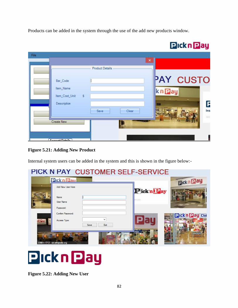
82
Products can be added in the system through the use of the add new products window.
Figure 5.21: Adding New Product
Internal system users can be added in the system and this is shown in the figure below:-
Figure 5.22: Adding New User

83
Products can be modified either the price or description. User simply clicks the drop down arrow
and selects the barcode of the commodity to be modified.
Figure 5.23: Managing Products
Objective 5 and Objective 6
Displaying of sales and customer reports and showing high spenders hence improving customer
relationship management through rewarding.
System Solution
System was developed such that is shows customer and sales reports and the amounts used to
purchase the products. This is shown in the form of a report as below:-

84
Figure 5.24: Customer Report
Figure 5.25: Sales Report

85
5.6.5 Constraints
According to Glattfelder (2012), a constraint is a factor that limits an organization from
achieving its set goals at the same time minimizing progress of this stated goal. Below are a list
of factors that hinder progress of the development of the customer self-service application for
Pick n Pay:-
Time factor – it was quite a challenge to manage time since there was need to focus on
school modules at the same time, system required extra attention so as to meet deadlines.
Unavailability of adequate information to facilitate research – it was difficult to
acquire information from the specified personnel since most of them felt like the new
system would make them lose their jobs at the same time, top management felt like some
of the information was sensitive hence were maintaining company confidentiality by not
saying out things as they are or not sharing the information at all.
Finance – finance was a major challenge since there was need for often visits to travel to
Pick n Pay for constant research and updates but this was difficult to do due to financial
barriers. At the same time, there are some software and hardware infrastructural
components that were required for the perfect running of the system but due to financial
problems researcher had to make the best out of what is already there.
5.6.6 Recommendations
There is need to conduct training for users to familiarize with the system.
In future there is need to link the mobile application with customer visa cards or Eco cash
debit card for payment purposes so as to avoid a routine of sales managers creating debit
cards.
There is need for system upgrades and maintenance to avoid malicious software
corrupting the system and slowing down operations.
Management recommended that the system should be merged with some of the modules
of the current system for consistency.
5.7 CONCLUSION
The chapter revealed all that is necessary for a successful set up of implementation of the
customer self-service application and the various security measures to be applied to secure the
system from unauthorized users. The success of the project have been seen but in every
successful project there are always many ways to improve its functionality than what it is. Pick n

86
Pay stores was impressed with the system functionality and they implemented a parallel change
over strategy for the sake of user familiarization of the system before a full system
implementation is done.
87
BIBLIOGRAPHY
1. Ackroyd S. and Hughes J.A (1981), Data Collection in Context, Longman
2. Atkinson, J., (1964), Handbook for Interviewers. London, HMSO
3. Bragg M.S (2006) outsourcing, john wiley and sons
4. Beizer B, (2007) Software system testing and quality assurance, Van Nostrand
Reinhold Company.
5. Chung L., Nixon B.A, Yu E., Mylopoulos J. (2012) Non-Functional Requirements in
Software Engineering, Springer Science & Business Media.
6. Craig R.D, Jaskiel S.P (2002), Systematic Software Testing, Artech House.
7. Daniel R. Windle, L. Abreo R. (2003), Software Requirements Using the Unified
Process, Prentice Hall Professional.
8. DENNIS AB, WIXOM H and TEGARDEN (2002) Systems Analysis & Design: An
9. Object Oriented Approach with UML, John Wiley & Sons, New York.
10. Desikan S. (2006), Software Testing: Principles and Practice, Pearson Education India.
11. Flynn M.J, Luk W, (2011), Computer System Design: System-on-Chip, John Wiley &
Sons.
12. Galitz W.O, (2007), The Essential Guide to User Interface Design: An Introduction
to GUI Design Principles and Techniques, 3rd
ed, John Wiley & Sons.
13. Glattfelder A.H, Schaufelberger W. (2012), Control Systems with Input and Output
Constraints, Springer Science & Business Media.
14. Hall, A. D. (1962). A Methodology for Systems Engineering, Van Nostrand. 478 p
15. HOFFER J.A, GEORGE J.F, and VALACICH J.S (2002) Modern Systems Analysis &
16. Design, Prentice Hall, Upper Saddle River, NJ.
17. Kassem A., Saleh J., (2009), Software Engineering, Packt Publishing Ltd.
18. Kerig P.K, Baucom D.H (2004), Couple Observational Coding Systems, Routledge.
19. Kelly A. (2006), Maintenance Systems and Documentation, Butterworth-Heinemann.
20. Kim D, Solomon M.G (2010), Fundamentals of Information Systems Security, Jones
& Bartlett Publishers.
21. Kulak D, Guiney E, (2012), Use Cases, 2nd
ed, Addison-Wesley, 2012

88
22. Michael O. Ibach (2001) Management information system: from concept to
implementation, CIFOR.
23. Ott R, Longnecker M., (2008), An Introduction to Statistical Methods and Data
Analysis, Cengage Learning.
24. Popper A, (1959), The Logic of Scientific Discovery, reprinted (2004) by Routledge,
Taylor & Francis
25. Saleh H. (2013), JavaScript Unit Testing, Packt Publishing Ltd.
26. Seffah A, Gulliksen A, Desmarais M.C, Human-Centered Software Engineering,
Springer Science & Business Media, 2006
27. Sward, David (2006). Measuring the Business Value of Information Technology.
28. Pardo R. (1992), Design, Testing, and Optimization of Trading Systems, John Wiley
& Sons.
29. Pusuluri N.R, (2006), Software Testing Concepts And Tools, Dreamtech Press.
30. Bryant, L., undated, 'Unstructured interviews' on History Learning Site (2002–2013)
available at http://www.historylearningsite.co.uk/unstructured_interviews.htm, accessed
30 July 2015.
31. Dennis A, Wixom H.B, Roth R.M, (2014) Systems Analysis and Design, John Wiley
&
Sons,http://www.businessdictionary.com/definition/processanalysis.html#ixzz3iVwYCod
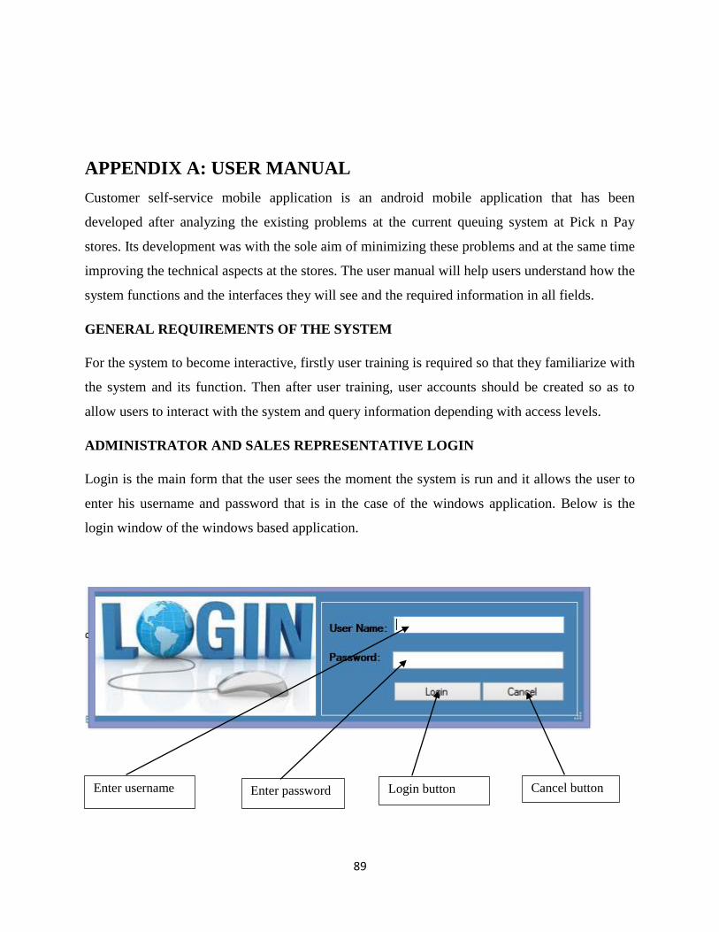
89
APPENDIX A: USER MANUAL
Customer self-service mobile application is an android mobile application that has been
developed after analyzing the existing problems at the current queuing system at Pick n Pay
stores. Its development was with the sole aim of minimizing these problems and at the same time
improving the technical aspects at the stores. The user manual will help users understand how the
system functions and the interfaces they will see and the required information in all fields.
GENERAL REQUIREMENTS OF THE SYSTEM
For the system to become interactive, firstly user training is required so that they familiarize with
the system and its function. Then after user training, user accounts should be created so as to
allow users to interact with the system and query information depending with access levels.
ADMINISTRATOR AND SALES REPRESENTATIVE LOGIN
Login is the main form that the user sees the moment the system is run and it allows the user to
enter his username and password that is in the case of the windows application. Below is the
login window of the windows based application.
Enter username Enter password Login button Cancel button

90
Figure A1: Login window
If user inputs incorrect credentials, the following window pops up:
Figure A2: Wrong username and password
Below is a window that appears if the administrator logs in successfully. The same window also
appears on the side of the sales rep but the only difference is that the sales rep does not have the
create user and delete users.

91
Figure A3: Administrator menu
Figure A4: Creating customer account
Click to view product list
Click to add new products
Click to add products
Click to view customer list
Click to create customer account
Click to update product list
Click to view customer deposits
Click to view customer balances
View sales report
Click to create user account
Click to delete users
Logout button
Enter customer name
Enter customer ID number
Enter phone number
Enter amount to be deposited
Save button Clear fields’ button

92
Figure A5: Adding products
Figure A6: Adding new user
Enter product barcode
Enter product name
Enter product price
Enter product description
Enter full name
Enter required username
Enter desired password
Confirm password
Select access type

93
The customer login portal on the mobile phone is different from that of the windows application.
It requires the customer to enter his or her virtual card number and pin code. The figure is shown
below.
Figure A7: Customer login
Enter card number
Enter pin code
Click button to sign in
Click button to register if querying
the system for the first time

94
This is the main menu that appears after customer has signed in.
Figure A8: Customer menu
After the user clicks start shopping the window below then appears.
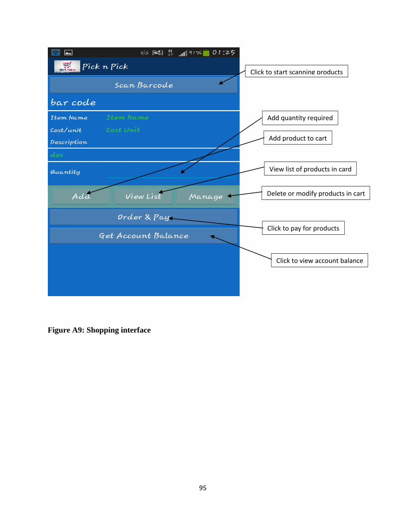
95
Figure A9: Shopping interface
Click to start scanning products
View list of products in card
Delete or modify products in cart
Click to pay for products
Add product to cart
Add quantity required
Click to view account balance

96
After product bar code has been scanned the following window with product details appears and
user has to specify the quantity of the product required.
Figure A10: Product results after scanning

97
APPENDIX B: INTERVIEW CHECKLIST
INTERVIEW QUESTIONS
1. How do you view the performance of the current system at Pick n Pay?
2. What is your view and suggestion in implementing the customer self-service mobile
application?
3. During times when there are more customers for example during festive season how do you
cope up with the pressures and is the system able to quickly update its database concurrently
without any errors striking?
4. Are there any controls that you would like to include in the event that an implementation of the
self-service application is done?
5. Who monitors the current system and direct linkage is to who?
6. Are there enough resources that will support in the running of the system in the event that we
decide to implement it?
7. What are the major disadvantages that you are facing in the operation of the current buyer
system and do you have any possible solutions that you can think of to curb these problems?
8. Do you have any suggestions or additions that you would wish to include in order to improve
proposed system performance?
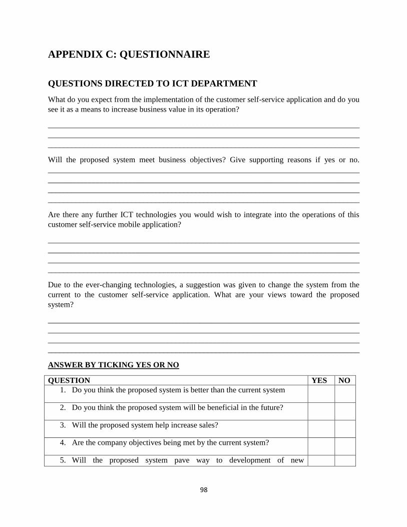
98
APPENDIX C: QUESTIONNAIRE
QUESTIONS DIRECTED TO ICT DEPARTMENT
What do you expect from the implementation of the customer self-service application and do you
see it as a means to increase business value in its operation?
______________________________________________________________________________
______________________________________________________________________________
______________________________________________________________________________
Will the proposed system meet business objectives? Give supporting reasons if yes or no.
______________________________________________________________________________
______________________________________________________________________________
______________________________________________________________________________
______________________________________________________________________________
Are there any further ICT technologies you would wish to integrate into the operations of this
customer self-service mobile application?
______________________________________________________________________________
______________________________________________________________________________
______________________________________________________________________________
______________________________________________________________________________
Due to the ever-changing technologies, a suggestion was given to change the system from the
current to the customer self-service application. What are your views toward the proposed
system?
______________________________________________________________________________
______________________________________________________________________________
______________________________________________________________________________
______________________________________________________________________________
ANSWER BY TICKING YES OR NO
QUESTION YES NO
1. Do you think the proposed system is better than the current system
2. Do you think the proposed system will be beneficial in the future?
3. Will the proposed system help increase sales?
4. Are the company objectives being met by the current system?
5. Will the proposed system pave way to development of new

99
technologies?
ADMINISTRATION DEPARTMENT
1. How do you rate the current system?
Excellent Good Fair Poor
2. Would you opt for mobile solutions if considered as a candidate from migrating from the
current system?
Yes No
If No, what may be the reason________________________________________
_________________________________________________________________
3. Do you often experience a system delay during busy days of operation?
Very often Sometimes All the time
4. Have some of employees or customers complained about the current system‟s performance?
Yes No
If YES what were the complaints?

100
APPENDIX D: OBSERVATION FORM
OBSERVATION SCORE SHEET
Name of observer: ____________________________________
Area under observation: _______________________________
Date: ___________________ Time: _________________
Focus of observation: ___________________________________________________________
Brief description of session:-
______________________________________________________________________________
______________________________________________________________________________
______________________________________________________________________________
______________________________________________________________________________
______________________________________________________________________________
______________________________________________________________________________
Areas of strength:-
______________________________________________________________________________
______________________________________________________________________________
______________________________________________________________________________
______________________________________________________________________________
______________________________________________________________________________
Comments:-
______________________________________________________________________________
______________________________________________________________________________
______________________________________________________________________________
______________________________________________________________________________
Signature: Manager______________________ Date: ______________________________

101
Signature: Observer______________________ Date: ______________________________
APPENDIX E: SAMPLE CODE
Personnel login
public partial class login : Form { connector con = new connector(); Boolean admin = false; public login() { InitializeComponent(); } private void button1_Click(object sender, EventArgs e) { Boolean logged = false; con.connectiondb(); string sql = "select * from usersadmin "; con.cmd = new SqlCommand(sql, con.cnn); con.reader = con.cmd.ExecuteReader(); while (con.reader.Read()) { if ((textBox1.Text == CryptorEngine.Decrypt(con.reader.GetString(0),true)) && (textBox2.Text == CryptorEngine.Decrypt(con.reader.GetString(1),true))) { logged = true; if(con.reader.GetString(2) =="Admin"){ admin = true; } } } if (logged) { this.Hide(); MessageBox.Show("Login successfull."); Form1 fm = new Form1(admin); fm.ShowDialog(); this.Close(); } else { MessageBox.Show("Login failed."); } }
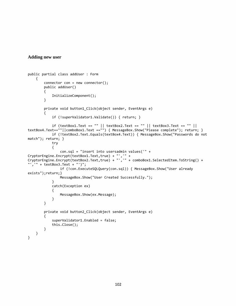
102
Adding new user
public partial class addUser : Form { connector con = new connector(); public addUser() { InitializeComponent(); } private void button1_Click(object sender, EventArgs e) { if (!superValidator1.Validate()) { return; } if (textBox1.Text == "" || textBox2.Text == "" || textBox3.Text == "" || textBox4.Text==""||comboBox1.Text =="") { MessageBox.Show("Please complete"); return; } if (!textBox2.Text.Equals(textBox4.Text)) { MessageBox.Show("Passwords do not match"); return; } try { con.sql = "insert into usersadmin values('" + CryptorEngine.Encrypt(textBox1.Text,true) + "','" + CryptorEngine.Encrypt(textBox2.Text,true) + "','" + comboBox1.SelectedItem.ToString() + "','" + textBox3.Text + "')"; if (!con.ExecuteSQLQuery(con.sql)) { MessageBox.Show("User already exists");return;} MessageBox.Show("User Created Successfully."); } catch(Exception ex) { MessageBox.Show(ex.Message); } } private void button2_Click(object sender, EventArgs e) { superValidator1.Enabled = false; this.Close(); } } }

103
Adding new product
if (!superValidator1.Validate()) { return; } connector con = new connector(); con.sql = "insert into Product(Bar_Code,Item_Name,Item_Cost_Unit,Item_Description) values('" + barcode.Text + "','" + itemname.Text + "','" + cost.Text + "','" + desc.Text + "')"; if (con.ExecuteSQLQuery(con.sql)) { MessageBox.Show("Success"); } else { MessageBox.Show("Failed to Load record. Make sure the product does not exist already"); } } private void buttonX2_Click(object sender, EventArgs e) { barcode.ResetText(); itemname.ResetText(); cost.ResetText(); desc.ResetText(); superValidator1.ClearFailedValidations(); } private void barcode_TextChanged(object sender, EventArgs e) { } private void itemname_TextChanged(object sender, EventArgs e) { } } }