Freud Vol 17 Pp 113 124 Trasposiciones de La Pulsion Anal 1917 oCS

PiCCO2 (PC8500)
Version 3.1
Operator´s Manual
and
Product Information
PULSION Medical Systems SE
Hans-Riedl-Str. 17
D-85622 Feldkirchen
Phone: +49 - (0)89 - 45 99 14 – 0
Fax +49 - (0)89 - 45 99 14 – 18
E-mail: [email protected]
Internet: www.PULSION.com
© PULSION EN 03/2013 March 2013
Art. No.: PC856EN_R11

About this Manual
Page II Operator’s Manual PiCCO2
Version 3.1
About this Manual
WARNING: Important items of information, i.e. activities where operating personnel must proceed with
extreme caution in order to avoid injury to themselves or the patient. These items of information are always
shown in BOLD.
CAUTION: Items of information for which careful attention must be paid in order to avoid damage to the
equipment or inaccurate data as well as operational errors. These items of information are always shown in
BOLD.
WARNING: Read the operating instructions carefully before using the PiCCO2 equipment!

Table of Contents
Operator´s Manual PiCCO2 Page
Version 3.1 III
Table of Contents
About this Manual ................................................................................................................................... II
Table of Contents ................................................................................................................................... III
List of Figures ...................................................................................................................................... VII
A General Information ..................................................................................................................... A-1
1 Intended Use ............................................................................................................................ A-1
2 Indications ................................................................................................................................ A-1
3 Contraindications ..................................................................................................................... A-2
4 Warnings .................................................................................................................................. A-3
5 Safety instructions .................................................................................................................... A-5
B Principles of Measurement and Parameters .............................................................................. B-1
1 Introduction .............................................................................................................................. B-1
2 Transpulmonary Thermodilution Technique ............................................................................. B-2
2.1 Principle .................................................................................................................................................. B-2
2.2 Transpulmonary Cardiac Output ............................................................................................................ B-2
2.3 Transpulmonary volume determination .................................................................................................. B-3
2.3.1 GEDV / ITBV ........................................................................................................................... B-3
2.3.2 EVLW ...................................................................................................................................... B-4
2.3.3 Additional Thermodilution Parameters .................................................................................... B-4
3 Continuous Pulse Contour Analysis ......................................................................................... B-5
3.1 Principle .................................................................................................................................................. B-5
3.2 Calibration of the Pulse Contour Cardiac Output ................................................................................... B-5
3.3 Continuous haemodynamic determination ............................................................................................. B-6
3.3.1 MAP / CVP / HR ...................................................................................................................... B-6
3.3.2 PCCO ...................................................................................................................................... B-6
3.3.3 SVV / PPV ............................................................................................................................... B-7
3.3.4 SVR ......................................................................................................................................... B-7
3.3.5 CPO ......................................................................................................................................... B-7
3.3.6 dPmx ....................................................................................................................................... B-7
4 Central venous oximetry .......................................................................................................... B-8
4.1 Principle .................................................................................................................................................. B-8
4.2 Determination of ScvO2 .......................................................................................................................... B-8
4.3 Oxygen delivery and oxygen consumption: DO2 and VO2 ...................................................................... B-8

Table of Contents
Page IV Operator’s Manual PiCCO2
Version 3.1
4.3.1 DO2 ...........................................................................................................................................B-8
4.3.2 VO2 ...........................................................................................................................................B-8
5 Pulse oximetry and pulse dye densitometry ............................................................................. B-9
5.1 Principle of pulse oximetry.......................................................................................................................B-9
5.2 Principle of pulse dye densitometry .........................................................................................................B-9
5.3 Principle of ICG elimination detection ....................................................................................................B-10
5.4 Parameters of pulse oximetry and pulse dye densitometry ...................................................................B-10
6 Parameter groups and ranges of normal values .................................................................... B-11
C Installation and setup ................................................................................................................... C-1
1 Unpacking and inspection ........................................................................................................ C-1
2 Functionality and user interaction ............................................................................................. C-3
2.1 Screen elements .................................................................................................................................... C-3
2.2 User interaction ...................................................................................................................................... C-3
2.2.1 Touchscreen ............................................................................................................................ C-4
2.2.2 Function keys .......................................................................................................................... C-4
2.2.3 Navigation dial and navigation keys ........................................................................................ C-5
3 Setup and measurement: Step by step .................................................................................... C-6
3.1 Connectors and connections .................................................................................................................. C-6
3.1.1 Patient cables .......................................................................................................................... C-6
3.1.2 Monitor connections ................................................................................................................ C-7
3.2 Patient and monitor wiring ...................................................................................................................... C-8
3.2.1 Thermodilution and Pulse Contour Analysis ............................................................................ C-9
3.2.2 Central venous oxygen saturation ......................................................................................... C-10
3.2.3 Application of injectate temperature sensor housing and CeVOX probe at the same time ... C-10
3.2.4 Transmission of continuous pressure to bedside monitor ..................................................... C-10
3.3 Setup and start ..................................................................................................................................... C-11
3.3.1 Mains voltage ........................................................................................................................ C-11
3.3.2 Switch on the device.............................................................................................................. C-11
3.4 Enter patient data ................................................................................................................................. C-12
3.5 Zero adjustment ................................................................................................................................... C-15
3.5.1 Zero adjustment of arterial pressure (AP) and central venous pressure (CVP) .................... C-15
3.6 Central venous oxygen saturation ........................................................................................................ C-16
3.6.1 ScvO2 calibration ................................................................................................................... C-16
3.6.2 SaO2 Input ............................................................................................................................. C-18
3.7 Indocyanine Green (ICG) measurement .............................................................................................. C-19

Table of Contents
Operator´s Manual PiCCO2 Page
Version 3.1 V
3.7.1 Non-invasive ICG measurement ........................................................................................... C-19
3.7.2 Display of results ................................................................................................................... C-21
3.7.3 Calculation of ICG quantity .................................................................................................... C-22
3.8 Thermodilution and calibration of pulse contour analysis ..................................................................... C-23
4 Display Options ...................................................................................................................... C-27
4.1 Information bar ..................................................................................................................................... C-27
4.2 Real time pressure curve ...................................................................................................................... C-28
4.3 Parameter fields ................................................................................................................................... C-29
4.4 Profiles.................................................................................................................................................. C-30
4.5 SpiderVision ......................................................................................................................................... C-31
4.6 Trend .................................................................................................................................................... C-32
5 Monitor and Display Configuration ......................................................................................... C-33
5.1 Patient settings ..................................................................................................................................... C-33
5.1.1 Information input .................................................................................................................... C-33
5.1.2 Predicted body weight ........................................................................................................... C-34
5.2 Monitor settings .................................................................................................................................... C-34
5.3 Configuration of parameter display ....................................................................................................... C-35
5.3.1 Setting of alarm limits ............................................................................................................ C-36
5.3.2 PCCI change warning ............................................................................................................ C-36
5.3.3 Parameter settings ................................................................................................................ C-37
5.4 Spider configuration .............................................................................................................................. C-38
5.5 Trend configuration ............................................................................................................................... C-39
5.6 Measurement configuration .................................................................................................................. C-40
5.6.1 Configuration of thermodilution measurement ....................................................................... C-40
5.6.2 Configuration of central venous catheter ............................................................................... C-41
5.6.3 Configuration of ScvO2 measurement ................................................................................... C-41
5.6.4 Configuration of ICG measurement ....................................................................................... C-41
5.7 Normal and Target Values .................................................................................................................... C-42
6 Alarms, messages and troubleshooting ................................................................................. C-43
6.1 Alarms .................................................................................................................................................. C-44
6.2 Error Messages .................................................................................................................................... C-44
6.3 Additional information ........................................................................................................................... C-47
7 Help Functions ....................................................................................................................... C-49
8 Printout .................................................................................................................................. C-50
8.1 USB Virtual Printing Option .................................................................................................................. C-50

Table of Contents
Page VI Operator’s Manual PiCCO2
Version 3.1
8.2 Label Printer ......................................................................................................................................... C-50
9 Battery Function ..................................................................................................................... C-51
10 Cleaning and Disinfection....................................................................................................... C-52
10.1 General remarks ................................................................................................................................... C-52
10.2 Precautions .......................................................................................................................................... C-52
10.3 Cleaning ............................................................................................................................................... C-53
10.4 Disinfection ........................................................................................................................................... C-53
D Disposables / Accessories .......................................................................................................... D-1
1 Disposables.............................................................................................................................. D-1
1.1 PiCCO Catheter (arterial thermodilution catheter) .................................................................................. D-1
1.2 PiCCO Monitoring Kits............................................................................................................................ D-2
1.3 Injectate Temperature Sensor Housing .................................................................................................. D-2
1.4 CeVOX probe ......................................................................................................................................... D-3
2 Accessories .............................................................................................................................. D-4
E Appendix ....................................................................................................................................... E-1
1 Technical Data ......................................................................................................................... E-1
2 Maintenance and Service ......................................................................................................... E-4
2.1 Classification ...........................................................................................................................................E-4
2.2 Maintenance ............................................................................................................................................E-4
2.3 Disposal of electrical and electronic equipment ......................................................................................E-5
3 Interfaces ................................................................................................................................. E-6
4 EMC-Requirements .................................................................................................................. E-7
5 Equations for Calculated Values ............................................................................................ E-11
5.1 General ..................................................................................................................................................E-11
5.2 Output ....................................................................................................................................................E-12
5.3 Preload Volume .....................................................................................................................................E-13
5.4 Afterload ................................................................................................................................................E-14
5.5 Contractility ............................................................................................................................................E-15
5.6 Organ Function ......................................................................................................................................E-15
5.7 Oxygenation ..........................................................................................................................................E-16
6 Flow chart............................................................................................................................... E-18
7 Symbols ................................................................................................................................. E-19
8 Warranty ................................................................................................................................ E-20

List of Figures
Operator´s Manual PiCCO2 Page
Version 3.1 VII
List of Figures
Page
Figure 1: Heart-lung circulation and resulting thermodilution curve B-2
Figure 2: GEDV / ITBV B-3
Figure 3: Extravascular Lung Water (EVLW) B-4
Figure 4: Global Ejection Fraction (GEF) B-4
Figure 5: Calibration of pulse contour analysis by means of thermodilution B-5
Figure 6: SVV B-7
Figure 7: PPV B-7
Figure 8: dPmx B-7
Figure 9: The principle of spectrophotometry B-8
Figure 10: Absorption spectra of O2Hb, Hb and ICG (According to Britton Chance, University of Pennsylvania) B-9
Figure 11: Schematic representation of the ICG elimination curve B-10
Figure 12: Screen elements C-3
Figure 13: Function keys C-4
Figure 14: Patient cables socket with equipment class (defibrillator protection) C-6
Figure 15: Monitor connections C-7
Figure 16: Patient and monitor wiring C-8
Figure 17: Start screen C-12
Figure 18: Catheter position C-13
Figure 19: Input screen C-14
Figure 20: "Zero adjustment" screen C-15
Figure 21: "ScvO2 calibration" screen: Blood sample withdrawal C-17
Figure 22: "ScvO2 calibration" screen: Input of lab values C-17
Figure 23: ScvO2 input screen C-21
Figure 24: PDR curve and results C-21
Figure 25: ICG calculator screen C-22

List of Figures
Page VIII Operator’s Manual PiCCO2
Version 3.1
Figure 26: "Thermodilution" screen C-23
Figure 27: Selection of “Inj. Volume” option with help screen “Recommended Inj. Volume” C-23
Figure 28: Recommended injectate volume depending on body weight C-25
Figure 29: Thermodilution curve C-26
Figure 30: Real time curve of arterial pressure C-28
Figure 31: Parameter fields C-29
Figure 32: "Profiles" screen C-30
Figure 33: "Spider" screen C-31
Figure 34: "Trend" screen C-32
Figure 35: "Patient settings" screen C-33
Figure 36: "Monitor settings" screen C-34
Figure 37: "Parameter configuration" screen C-35
Figure 38: "Spider configuration" screen C-38
Figure 39: "Trend configuration" screen C-39
Figure 40: "Measurement configuration" screen C-40
Figure 41: Normal- / Target value range C-42

General Information
Operator´s Manual PiCCO2 Page
Version 3.1 A-1
A General Information
1 Intended Use
The PULSION PiCCO2´s intended use is the minimally invasive determination and monitoring of
cardiopulmonary and circulatory variables. Along with other bedside monitors and the clinical evaluation, the
PiCCO2 detects the patient´s status and evaluates the need for and the suitability of treatment methods for the
care of critically ill patients in intensive care units as well as for perioperative monitoring. If a patient´s correct
weight and height are entered, the PiCCO2 presents the derived parameters indexed to the patient´s body
characteristics.
The PiCCO2 uses up to four technologies:
1. Transpulmonary thermodilution measurement for discontinuous determination of cardiac output and intra-
and extravascular fluid volumes.
2. Arterial pulse contour analysis for the continuous determination of cardiac output, volume responsiveness
and other derived parameters.
3. Fiberoptic reflective measurement for the determination of oxygen saturation in the blood.
4. Pulse oximetry for continuous monitoring of the functional oxygen saturation of arterial haemoglobin
(SpO2) and pulse densitometry for the determination of the concentration of Indocyanine Green, a dye
approved as a diagnostic drug.
The transpulmonary thermodilution technique and the arterial pulse contour analysis are not classified as
measuring functions as stated in the Council Directive 93/42/EEC.
The PiCCO2 is intended for use in hospitals and hospital-like facilities and by trained health care
professionals.
The PiCCO2 can be used in environments stated in the IEC 60601-1-1 Standard.
2 Indications
The use of the PiCCO2 is indicated in patients where cardiovascular and circulatory volume status monitoring
is necessary. This includes patients undergoing surgical interventions of such magnitude that cardiovascular
monitoring is necessary.
Continuous monitoring of central venous oxygen saturation is indicated in all intensive care patients
particularly in the case of sepsis and multi-organ failure; management of early goal directed therapy in severe
sepsis; for intra-operative monitoring of high risk surgical patients and in emergency medicine and acute-care
for fast track evaluation of the patient´s haemodynamic condition.
The Indocyanine Green concentration and elimination measurement is indicated in all patients with persistent
or expected limitations of the global liver function (cellular function or perfusion).

General Information
Page A-2 Operator’s Manual PiCCO2
Version 3.1
3 Contraindications
The invasive technologies in the PiCCO2 should not be used in patients where the placement of an indwelling
arterial catheter or a central venous catheter is contraindicated. The PiCCO2 should only be used in patients
where the expected results are reasonable in comparison to the risks. Patients on intra-aortic balloon counter
pulsation (IABP) cannot be monitored with the pulse contour analysis of the device. Transpulmonary
thermodilution however works during IABP support.
WARNING: Federal (USA) law restricts this device for sale by or on the order of a physician.
The device is intended for use in hospitals and hospital-like facilities by trained and informed health
care professionals.
For contraindications of the diagnostic drug, Indocyanine Green, please refer to the corresponding SPC
(summary of product characteristics).

General Information
Operator´s Manual PiCCO2 Page
Version 3.1 A-3
4 Warnings
WARNING
General:
Federal (USA) law restricts this device to sale by or on the order of a physician.
The device is intended for use in hospitals and hospital-like facilities by trained and informed health care
professionals.
Before using the PiCCO2 equipment carefully read the operating instructions for the device and the used
disposables. The use of the PiCCO2 in contradiction to the instructions in this manual may cause undue
equipment failure and possible health hazards.
For safety of operation and for accuracy of measurements, only disposables and accessories approved by
PULSION Medical Systems may be used with the PiCCO2.
Explosion hazard when used in the presence of flammable anesthetics.
For safety of operation, only memory sticks and printers approved by PULSION Medical Systems may be
used with the PiCCO2.
Positioning / Installation:
Position the equipment in such a manner that neither the device nor other equipment attached to the
device can fall on the patient. Never lift or carry the device by the mains supply cable or the cable attached
to the patient.
When using the provided assembly facilities pay attention to a correct installation. The used system must
be sufficiently stable and tilt resistant as well as medically approved. In order to ensure a secure
connection with the mounting system the locking mechanism of the universal adapter plate must be
completely snapped in place.
Place the cables attached to the patient carefully so that the patient is not in danger of becoming
entangled or strangulating him/herself with the cables.
Medical:
The device enables the monitoring of physiological parameters. The clinical significance of changes in the
monitored parameters must be determined by a physician.
If a new patient is connected to the device without the device being shut down, the procedure "New
Patient" must be selected. Otherwise data from the last patient is still displayed.
The PiCCO2 may only be regarded as a device providing early warning. If there is an indication of a trend
towards de-oxygenation of the patient, blood samples must be taken and tested on a laboratory oximeter
in order to arrive at a decision concerning the condition of the patient.
The device must not be used for monitoring breathing.
The device must not be used for monitoring heart rate, arterial blood pressure and body temperature.
Before using the device the setting of the alarm limits and the alarm volume must be checked regarding
their suitability for the respective patient.

General Information
Page A-4 Operator’s Manual PiCCO2
Version 3.1
If an alarm condition arises while the alarm is suppressed, only the optical warning will be given.
During the start up procedure an acoustic sound appears at the end of the activation time. If this sound
does not appear no acoustic alarm can take place.
External influences: carboxyhaemoglobin can result in incorrect high values for SpO2. The degree of
elevation is approximately equal to the amount of carboxyhaemoglobin present. Dye (e.g. Indocyanine
Green) or other substances which contain dyes which usually modify the light absorption capacities, can
lead to faulty measurement values of the oxygen saturation.
The measurement of SpO2 is not recommended for patients weighing less than 20 kg (44lbs).
Do not use the device while a NMR scan is being carried out. An induced voltage can result in potential
burns.
Disposables:
When placing the arterial catheter into a large artery (e.g. femoral, brachial or axillary artery) do not
advance the tip of the catheter into the aorta.
An intracardiac blood pressure measurement is not allowed. This means that the measuring position
(i.e.catheter tip) must not be in the heart.
Further use of disposable items is not allowed. Re-sterilization of disposables may cause infections in the
patient.
Incorrect use of the ScvO2 probe can lead to vessel perforation. Therefore check the correct position of the
probe as indicated in the probe´s instructions for use.
Electrical:
Do not use damaged probes or patient cables. Do not use any probes with exposed optical or electrical
components.
Do not reconnect the PiCCO2 to electrical power if liquid has entered the device. A short circuit may
damage the device and cause hazardous conditions for patient and user.
Remove patient cables which are not needed. The used components are not galvanically isolated from
each other.
The PiCCO2 always has to be connected with the protective earth conductor. Never use mains supply
cable or extension lines without protective earth conductor.
Connect the potential equalization at the back of the device with the potential equalization system of the
treatment room.

General Information
Operator´s Manual PiCCO2 Page
Version 3.1 A-5
5 Safety instructions
CAUTION
General:
Do not expose the PiCCO2 to temperatures above 40 °C (104 °F) or below 10 °C (50 °F). The accuracy of
the measured values may be affected.
Do not pull on the probes or cables in order to remove them from the device. Observe the instructions for
use for the probes in order to ensure that a technically correct procedure is carried out.
Do not place other equipment or containers with liquid on top of the PiCCO2.
Never place the cables in water or other cleaning solutions. The cables and connections are not water-
tight. Never sterilize the cables by radiation, steam or gas.
Do not use abrasive or sharp-edged tools to clean the optical module as this may damage or destroy
optical components.
If the device is not standing on a slip-proof surface and to prevent displacement, hold the unit securely
while the function keys are being pressed.
Preparations for Use:
The user must assure him-/herself of the safe and fully functional condition of the equipment before using
it.
If the PiCCO2 appears to be damaged, contact your local PULSION representative. Do not use the PiCCO2
if the device appears to be damaged.
If the system check detects a failure, no function will be available and “SERVICE” is displayed on the
screen. Turn the PiCCO2 off and contact your local PULSION representative. Do not attempt to use or
repair the PiCCO2.
When the PiCCO2 is connected to a bedside monitor, perform a zero adjustment of the PiCCO2 before
zeroing the bedside monitor.
Medical:
If the zero adjustment is not performed, the blood pressure values may be wrong. Zero adjustment of the
pressure transducer is mandatory.
When restoring the calibration in the PCCO and ScvO2 calibration menu an old calibration factor may be
used. Ensure that the values are plausible after having used this option.
If the displayed pulse contour parameters are not plausible, they should be checked by a thermodilution
measurement. The pulse contour cardiac output measurement will be recalibrated automatically.
As the pulse contour cardiac output of children has not been sufficiently validated so far the CO should be
checked by thermodilution before therapeutic interventions.

General Information
Page A-6 Operator’s Manual PiCCO2
Version 3.1
Recalibration is recommended with significant changes in haemodynamic conditions, such as volume
shifts or changes to medication.
If the option of the continuous CVP measurement is not used, CVP should be updated as soon as a new
value is obtained to accurately calculate SVR and PCCO.
Faulty measurements can be caused by incorrectly placed catheters, interfering signal transmission e.g. of
arterial pressure, defective connections or sensors or by electromagnetic interference (e.g. electric
blankets, electric coagulation).
Due to an aortic aneurysm the displayed blood volume (GEDV/ITBV) derived by a thermodilution
measurement can be erroneously high.
Electrical:
The PiCCO2 is subject to specific precautions concerning EMC (Electromagnetic compatibility) and is only
allowed to be installed and used according the EMC advice contained in this user´s manual. Portable and
mobile high frequency communication devices may influence the PiCCO2.
Any additional item of equipment which is connected to the digital interface must satisfy the EMC
requirements of the IEC specification 60601-1-2.
Furthermore, all configurations have to meet the system standard IEC 60601-1-1. Any person who
connects additional devices to the signal input or signal output of the PiCCO2 is changing the system
configuration and is responsible for observing the requirements of the IEC 60601-1-1 standard.
When high frequency devices are used during surgery, the applying standards for high frequency devices
for surgery have to be followed.
Check the battery state of charge when using the device. Only when the battery is fully charged, the use of the device can be ensured for the stated time without being connected to the mains.
If the connection to the protective earth conductor cannot be ensured, separate the device from the mains
supply and only use the device on battery power.

Principles of Measurement and Parameters
Operator´s Manual PiCCO2 Page
Version 3.1 B-1
B Principles of Measurement and Parameters
1 Introduction
The PiCCO2 is a device for continuous cardiac output measurement combined with monitoring of cardiac
preload volume, extravascular lung water, arterial and central venous oxygen saturation and global liver
function.
The PULSION PiCCO2 computes the CO continuously, utilizing an improved arterial pulse contour analysis
algorithm. The Pulse Contour Cardiac Output (PCCO) is calibrated by means of a transpulmonary
thermodilution measurement. A cold or room-temperate bolus (e.g. normal saline 0.9%) is injected through a
central venous catheter. A thermodilution curve is recorded by an arterial thermodilution catheter, which also
serves for pressure monitoring. In addition to calibration of the PCCO, transpulmonary thermodilution also
yields cardiac preload by means of global end-diastolic volume (GEDV) and an estimation of both,
intrathoracic blood volume (ITBV) and extravascular lung water (EVLW).
Furthermore the PiCCO2 continuously measures the central venous oxygen saturation (ScvO2) after
calibration with blood gas analysis results and can continuously calculate oxygen delivery (DO2) and oxygen
consumption (VO2).
Detection of concentration and determination of the elimination rate of a diagnostic drug, Indocyanine Green,
provide information about the global liver function. The device indicates the Plasma Disappearance Rate
(PDR) and the Retention Rate of ICG after 15 minutes (R15).
To derive parameters, the PiCCO2 combines transpulmonary thermodilution technique with continuous arterial
pulse contour analysis and fiberoptic oximetry and pulse oximetry/densitometry. Oximetry measurements use
different wave lengths for the determination of the elimination rate of Indocyanine Green.
If a patient´s weight, height, category and gender are entered, the PiCCO2 presents the derived parameters
indexed to the patient´s body characteristics.

Principles of Measurement and Parameters
Page B-2 Operator’s Manual PiCCO2
Version 3.1
2 Transpulmonary Thermodilution Technique
2.1 Principle
To accomplish thermodilution determination a known volume of a suitable indicator (at least 10°C below blood
temperature) is injected intravenously as quickly as possible. The recorded downstream temperature change
is dependent on the flow and the volume through which the cold indicator has passed. As a result, a
thermodilution curve can be recorded. The PiCCO2 detects the cold indicator in the arterial system (preferably
in the femoral artery).
Figure 1: Heart-lung circulation and resulting thermodilution curve
2.2 Transpulmonary Cardiac Output
Cardiac Output (CO) is the volume of blood being pumped by the heart in one minute.
Cardiac output by thermodilution is calculated according to the Stewart-Hamilton formula (see Appendix)
using the area under the thermodilution curve.
Absolute Parameters Indexed Parameters
Parameter Abbr. Unit Abbr. Unit
Cardiac output, transpulmonary CO l/min CI l/min/m2

Principles of Measurement and Parameters
Operator´s Manual PiCCO2 Page
Version 3.1 B-3
2.3 Transpulmonary volume determination
Specific volumes can be calculated by multiplying cardiac output with characteristic time variables of the
thermodilution curve.
The parameters can alternatively be displayed as absolute parameters or indexed to the patient´s body
characteristics.
The PiCCO2 uses predicted body weight (PBW) to index intrathoracic volumetric parameters.
Absolute Parameters Indexed Parameters
Parameter Abbr. Unit Abbr. Unit
Global End-Diastolic Volume GEDV ml GEDI ml/m2
Extravascular Lung Water EVLW ml ELWI ml/kg
Global Ejection Fraction GEF %
Pulmonary Vascular Permeability Index PVPI -
Cardiac Function Index CFI 1/min
Intrathoracic Blood Volume ITBV ml ITBI ml/m2
2.3.1 GEDV / ITBV
GEDV ITBV
Figure 2: GEDV / ITBV
Global End-Diastolic Volume (GEDV) is the total amount of blood left in all four heart chambers, i.e. atria and
ventricles, at the end of diastole.
Intrathoracic Blood Volume (ITBV) represents the total amount of blood in the thorax.
GEDV and ITBV reflect the circulatory volume status and are excellent indicators of cardiac preload. GEDV
and ITBV are used for managing the patient´s vascular filling status and guiding volume therapy.
CAUTION: Aortic aneurysms may cause the displayed blood volume (GEDV/ITBV) derived by
thermodilution measurement to be erroneously high.

Principles of Measurement and Parameters
Page B-4 Operator’s Manual PiCCO2
Version 3.1
2.3.2 EVLW
EVLW quantifies the extravascular fluid volume in the lungs. It is used to alert the clinician to the existence or
development of pulmonary edema. When measuring lung water the intra-alveolar, intracellular and interstitial
lung water are considered. However, a pleural effusion does not influence measurements.
Figure 3: Extravascular Lung Water (EVLW)
2.3.3 Additional Thermodilution Parameters
2.3.3.1 GEF:
GEF mainly depends on right and left ventricular contractility and can be used to detect right and/or left
ventricular dysfunction. GEF is derived from the ratio of four stroke volumes divided by Global End-
Diastolic Volume (GEDV).
Figure 4: Global Ejection Fraction (GEF)
2.3.3.2 CFI:
CFI represents the ratio between cardiac output and global end-diastolic volume (GEDV).
2.3.3.3 PVPI
PVPI shows the relationship between EVLW and PBV (Pulmonary Blood Volume) and can help to
distinguish between hydrostatic and permeability caused pulmonary edema.

Principles of Measurement and Parameters
Operator´s Manual PiCCO2 Page
Version 3.1 B-5
3 Continuous Pulse Contour Analysis
3.1 Principle
The relationship between blood flow out of the aorta and pressure measured near the aorta (femoral artery or
other large artery) is determined by the compliance function. The compliance function can therefore be
characterized by measuring blood pressure and blood flow (cardiac output) simultaneously. Transpulmonary
thermodilution cardiac output determined simultaneously with continuous arterial pressure measurement is
utilized to calibrate the pulse contour analysis to each individual patient´s aortic compliance function.
3.2 Calibration of the Pulse Contour Cardiac Output
To calibrate the measurement of continuous cardiac output, a reference thermodilution cardiac output is
necessary. The PiCCO2 uses the transpulmonary thermodilution as reference method.
Figure 5: Calibration of pulse contour analysis by means of thermodilution

Principles of Measurement and Parameters
Page B-6 Operator’s Manual PiCCO2
Version 3.1
3.3 Continuous haemodynamic determination
The following parameters are derived by the PULSION PiCCO2 , analyzing the arterial pressure curve beat by
beat. The parameters can alternatively be displayed as absolute parameters or indexed to the patient´s body
characteristics.
Absolute Parameters Indexed Parameters
Parameter Abbr. Unit Abbr. Unit
Pulse Contour Cardiac Output PCCO l/min PCCI l/min/m2
Stroke Volume SV ml SVI ml/m2
Systemic Vascular Resistance SVR dyn•s•cm-5 SVRI dyn•s•cm-5•m2
Stroke Volume Variation SVV %
Pulse Pressure Variation PPV %
Left Ventricular Contractility dPmx mmHg/s
Cardiac Power Output CPO W CPI W/m²
Heart Rate HR min-1
Mean Arterial Blood Pressure MAP mmHg
Systolic Arterial Blood Pressure APsys mmHg
Diastolic Arterial Blood Pressure APdia mmHg
Moreover, central venous pressure (CVP) in mmHg can be measured continuously.
3.3.1 MAP / CVP / HR
MAP (Mean Arterial Pressure)
Mean arterial pressure is the mean value of the blood pressure in the arterial system.
CVP (Central Venous Pressure)
Central venous pressure is the average blood pressure directly before the right heart.
HR (Heart Rate)
Heart rate is the number of heart beats per minute.
3.3.2 PCCO
Pulse contour cardiac output is the continuously determined cardiac output from the pulse contour analysis.
CAUTION: As the pulse contour cardiac output of children has not been sufficiently validated thus
far, the CO should be checked by thermodilution before therapeutic interventions.
Recalibration is recommended with significant changes in haemodynamic conditions, such as
volume shifts or changes to medication.

Principles of Measurement and Parameters
Operator´s Manual PiCCO2 Page
Version 3.1 B-7
3.3.3 SVV / PPV
SVV is the variation in stroke volume over a certain time.
Figure 6: SVV
PPV is the variation in pulse pressure over a certain time.
PPPPmaxmax
PPPPminmin
PPPPmaxmax
PPPPminmin
Figure 7: PPV
In mechanically ventilated patients without arrhythmias SVV and PPV enable an estimation of the volume
responsiveness. Large variations in stroke volume or pulse pressure induced by mechanical ventilation
indicate that volume loading will lead to an increase in cardiac ejection (volume responsiveness).
3.3.4 SVR
SVR represents the resistance the blood encounters as it flows through the vascular system. The SVR value
is often used by clinicians as an estimate of afterload.
3.3.5 CPO
The CPO is the product of cardiac output and mean arterial pressure, thus reflecting the cardiovascular blood
flow related to the counteractive resistance. CPO serves as an indicator for the overall performance of the
heart.
3.3.6 dPmx
dPmx is the abbreviation for ΔPmax/Δt. This parameter indicates how fast the aortic pressure is rising during
systole. It allows a close approximation of the contractility of the left ventricle. In addition to CFI/GEF, dPmx
can be used to manage the administration of positive inotropic and cardiovascular agents.
Figure 8: dPmx

Principles of Measurement and Parameters
Page B-8 Operator’s Manual PiCCO2
Version 3.1
4 Central venous oximetry
4.1 Principle
The PiCCO2 measures central venous oxygen saturation (ScvO2) by spectrophotometry. Spectrophotometry
involves the use of light emitting diodes (LED) that produce light of various wavelengths in red and infrared
spectra. The light is transmitted to the blood through a fiberoptic in the probe, reflected off the red blood cells
and transmitted back through a separate fiberoptic to an optical module.
Figure 9: The principle of spectrophotometry
The wavelengths are selected in a way that the absorption characteristics of haemoglobin and
oxyhaemoglobin are different. Given both the amount of total haemoglobin and the amount of haemoglobin
bound to oxygen, oxygen saturation can be calculated.
4.2 Determination of ScvO2
ScvO2 reflects the oxygen saturation of the haemoglobin in the blood in the superior vena cava directly before
the right atrium. It is an early indicator of an imbalance between oxygen delivery and oxygen consumption.
Thus this parameter early indicates a threat to global tissue oxygenation.
Absolute Parameters
Parameter Abbr. Unit
Central Venous Oxygen Saturation ScvO2 (%)
4.3 Oxygen delivery and oxygen consumption: DO2 and VO2
Absolute Parameters Indexed Parameters
Parameter Abbr. Unit Abbr. Unit
Oxygen delivery DO2 ml/min DO2I ml/min/m2
Oxygen consumption VO2 ml/min VO2I ml/min/m2
4.3.1 DO2
DO2 is the amount of oxygen provided to the tissue per minute. It depends on the flow (cardiac output), the
amount of haemoglobin in the blood and the arterial oxygen saturation.
4.3.2 VO2
VO2 is the amount of oxygen consumed by the tissue per minute.

Principles of Measurement and Parameters
Operator´s Manual PiCCO2 Page
Version 3.1 B-9
5 Pulse oximetry and pulse dye densitometry
5.1 Principle of pulse oximetry
Pulse oximetry measures the percentage oxygen saturation of the haemoglobin. The principle of pulse
oximetry is based on the transmission and absorption of light waves in the visible and near-infrared spectrum
by haemoglobin. Light of different wavelengths is sent through the tissue non-invasively and is subsequently
detected by a sensor. The received light signal is used to determine the oxygen saturation. This measurement
is entirely non-invasive.
Pulse oximetry is used to measure the partial oxygen saturation of haemoglobin i.e. only oxygenated and
deoxygenated haemoglobin is included. However, not included is e.g. carboxyhaemoglobin or
methaemoglobin.
WARNING: External influences: carboxyhaemoglobin can result in incorrect high values for SpO2.
The degree of elevation is approximately equal to the amount of carboxyhaemoglobin present.
Dye (e.g. Indocyanine Green) or other substances which contain dyes which usually modify the
light absorption capacities, can lead to faulty measurement values of the oxygen saturation.
WARNING: The measurement of SpO2 is not recommended for patients weighing less than
20 kg (44lbs).
5.2 Principle of pulse dye densitometry
The principle of pulse dye densitometry and with it, the measurement of the plasma disappearance rate of
Indocyanine Green (ICG) is based on pulse oximetry. The difference is that other light wavelengths are used
than with pulse oximetry.
Figure 10: Absorption spectra of O2Hb, Hb and ICG (According to Britton Chance, University of Pennsylvania)

Principles of Measurement and Parameters
Page B-10 Operator’s Manual PiCCO2
Version 3.1
5.3 Principle of ICG elimination detection
ICG has an absorption maximum of approximately 805 nm. The determination of ICG concentration within this
range (optical window) is not disturbed by other blood components.
The trend in ICG concentration over time is used to calculate the relative change in percent per minute. The
plasma disappearance rate (PDR) of ICG is a measure of the excretory capacity of the liver and thus global
liver function. It is influenced by the function of liver cells as well as the liver perfusion. Depending on the
patients underlying disease the PDR helps to assess the patient´s liver function and/or liver perfusion. As the
liver is part of the splanchnic area, splanchnic perfusion can be indirectly estimated.
Figure 11: Schematic representation of the ICG elimination curve
The figure above shows a typical ICG concentration curve with the initial peak and its course over
500 seconds. The elimination measurement starts after thorough mixing of ICG with the circulating blood
volume. The starting point of the PDR measurement is determined dynamically dependent on the circulation
time derived from the first peak. The ICG curve analysis continues for five to ten minutes, dependent on the
quality of the curve.
The starting point represents 100%. The algorithm detects a percentage decrease per minute and indicates
the PDR in percent per minute.
NOTE
For information on the diagnostic drug, Indocyanine Green, please refer to the corresponding
SPC (summary of product characteristics) or PIL (patient information leaflet) of ICG.
5.4 Parameters of pulse oximetry and pulse dye densitometry
The following parameters are measured by pulse dye densitometry and pulse oximetry:
Arterial oxygen saturation SpO2 (%)
Plasma Disappearance Rate of ICG PDR (%/min)
Retention Rate of ICG after 15 minutes R15 (%)

Principles of Measurement and Parameters
Operator´s Manual PiCCO2 Page
Version 3.1 B-11
6 Parameter groups and ranges of normal values
The normal value ranges are based upon clinical experience and can vary from patient to patient. The stated
values are therefore offered without guarantee. Indexed parameters are related to body surface area,
predicted body weight or predicted body surface area (see Appendix) and can also be displayed as absolute
values.
Parameter Normal Ranges Unit
Flow CI / PCCI 3.0 – 5.0 l/min/m2
SVI 40 – 60 ml/m2
Preload Volume GEDI 680 – 800 ml/m2
ITBI 850 – 1000 ml/m2
SVV < 10 %
PPV < 10 %
Afterload SVRI 1700 – 2400 dyn•s•cm-5•m2
Contractility GEF 25 – 35 %
CFI 4.5 – 6.5 1/min
dPmx - mmHg/s
Organ Function ELWI 3.0 – 7.0 ml/kg
PVPI 1.0 – 3.0 -
CPI 0.5 – 0.7 W/m2
PDR 18 – 25 %/min
R15 0 – 10 %
Oxygenation ScvO2 70 - 80 %
DO2I 400 – 650 ml/min/m2
VO2I 125 – 175 ml/min/m2
SpO2 90 – 100 %
NOTE
PULSION is a medical device manufacturer and does not practice medicine. PULSION does not
recommend these values for use on a specific patient. The treating physician is in any case
responsible for determining and utilizing the appropriate diagnostic and therapeutic measures for
each individual patient.

Principles of Measurement and Parameters
Page B-12 Operator’s Manual PiCCO2
Version 3.1
WARNING: The PiCCO2 equipment may only be regarded as a device providing early warning. If
there is an indication of a trend towards de-oxygenation of the patient, blood samples must be
taken and tested on a laboratory oximeter in order to arrive at a decision concerning the condition
of the patient.
The device must not be used for monitoring breathing.
The device must not be used for monitoring heart rate, arterial blood pressure and body
temperature.

Installation and setup
Operator´s Manual PiCCO2 Page
Version 3.1 C-1
C Installation and setup
CAUTION: The user must assure him-/herself of the safe and fully functional condition of the
equipment before using it.
1 Unpacking and inspection
Inspect the packaging for possible shipping damage. Use care when unpacking the PiCCO2. Retain the
packing slip and save all packing material in case the device is damaged or fails the self test and has to be
returned to the manufacturer.
WARNING: Before using the PiCCO2 equipment carefully read the operating instructions for the
device and the used disposables. The use of the PiCCO2 in contradiction to the instructions in this
manual may cause undue equipment failure and possible health hazards.
Position the equipment in such a manner that neither the device nor other equipment attached to
the device can fall on the patient. Never lift or carry the device by the mains supply cable or the
cable attached to the patient.
When using the provided assembly facilities pay attention to a correct installation. The used
system must be sufficiently stable and tilt resistant as well as medically approved. In order to
ensure a secure connection with the mounting system the locking mechanism of the universal
adapter plate must be completely snapped in place.
CAUTION: If the PiCCO2 appears to be damaged, contact your local PULSION representative.
Do not use the PiCCO2 if the device appears to be damaged.
If the system check detects a failure, no function will be available and “SERVICE” is displayed on
the screen. Turn the PiCCO2 off and contact your local PULSION representative. Do not attempt to
use or repair the PiCCO2.

Installation and setup
Page C-2 Operator’s Manual PiCCO2
Version 3.1
- Blank page -

Installation and setup
Operator´s Manual PiCCO2 Page
Version 3.1 C-3
2 Functionality and user interaction
2.1 Screen elements
Figure 12: Screen elements
1) Information bar
Information bar for patient and measurement specific information and error messages
2) Real Time pressure curve
Permanent display of real time pressure curve of arterial pressure (AP) and central venous pressure (CVP)
3) Parameter fields
Configurable parameter fields divided into parameter groups, permanent display of the selected parameters
4) Patient screen
Function area for measurements, configuration and graphical display of parameters
5) Display options
The determined parameters can be displayed in 3 different ways. (for details see chapter C4)
6) Selection of actions
Direct access to thermodilution measurement, ScvO2 calibration, ICG measurement and zero adjustment of
blood pressure (dependent on setting and connected module)
2.2 User interaction
The PiCCO2 provides an intuitive user interface and can be operated by both navigation dial and touch
screen. In order to keep navigation as easy as possible, actions and settings can be done by direct activation
of the respective screen element on the screen.

Installation and setup
Page C-4 Operator’s Manual PiCCO2
Version 3.1
2.2.1 Touchscreen
Measurement and display options as well as any configuration can be reached directly by touching the
respective element on the touch screen. All input can be directly made on the screen. Numerics can be
directly entered on the screen by means of a touch keyboard.
To switch to another screen just select another element on the screen or use the Main button.
2.2.2 Function keys
Figure 13: Function keys
ON/OFF key: This key is used to switch the device on and off. As soon as the mains power switch is pressed
at the rear side of the device, a green light appears. The green light indicates that the device is connected to
the mains power supply. A blinking green light indicates that the battery is being charged. By pressing the key
continuously for 4 seconds during operation, the device will shutdown and restart.
Opening the help screen
Print key: Starts a printout, depending on the connected printer device (USB or thermal transfer printer)
Mute key: Pausing of the alarm for 2 minutes. The orange light indicates an alarm even if there is an acoustic
alarm pause.

Installation and setup
Operator´s Manual PiCCO2 Page
Version 3.1 C-5
2.2.3 Navigation dial and navigation keys
Back key: Back to previous interaction level.
Main key: Back to the last active display screen
Navigation dial:
The navigation dial can be used alternatively to the touch screen. The currently active position will be
displayed by a white frame on the screen. Pressing the navigation dial confirms the selection.

Installation and setup
Page C-6 Operator’s Manual PiCCO2
Version 3.1
3 Setup and measurement: Step by step
3.1 Connectors and connections
3.1.1 Patient cables
SO2
Connection of the CeVOX module or
LiMON module
CO
Connection of temperature interface cable
for arterial thermodilution catheter and
injectate temperature sensor.
AP
Connection of pressure transfer cable for
arterial pressure (AP)
CVP
Connection of pressure transfer cable for
central venous pressure (CVP)
Figure 14: Patient cables socket with equipment class (defibrillator protection)
NOTE
PiCCO2 is protected against electric shock in case of defibrillation.
WARNING: Do not use damaged probes or patient cables. Do not use any probes with exposed optical or electrical components.
Do not reconnect the PiCCO2 to electrical power if liquid has entered the device. A short circuit may damage the device and cause hazardous conditions for patient and user.
Remove patient cables which are not needed. The used components are not galvanically isolated from each other.
Place the cables attached to the patient carefully so that the patient is not in danger of becoming
entangled or strangulating him/herself with the cables.

Installation and setup
Operator´s Manual PiCCO2 Page
Version 3.1 C-7
3.1.2 Monitor connections
Figure 15: Monitor connections
1) AP / CVP
Transfer of continuous arterial pressure (AP) and central venous pressure (CVP) signal to bedside monitor
2) Serial Interface RS232
Connection for patient data acquisition systems (PDMS)
3) LAN
Connection for network devices for printing and data transfer
4) USB ports (2)
Connection for external printer and PULSION memory stick
5) Potential equalization
Connection for potential equalization cable
6) Mains power connector
Connects the monitor to the power socket
7) Mains switch
WARNING: Connect the potential equalization at the back of the device with the potential
equalization system of the treatment room.
CAUTION: Any additional item of equipment which is connected to the digital interface
must satisfy the requirements of the current IEC specification.

Installation and setup
Page C-8 Operator’s Manual PiCCO2
Version 3.1
3.2 Patient and monitor wiring
Figure 16: Patient and monitor wiring
Thermodilution measurement, pulse contour analysis and pulse oximetry/densitometry can work
independently from central venous oxygen saturation measurement.
WARNING: Please consult the instructions for use accompanying the disposables and
accessories.

Installation and setup
Operator´s Manual PiCCO2 Page
Version 3.1 C-9
3.2.1 Thermodilution and Pulse Contour Analysis
Disposables:
(1) Arterial Thermodilution Catheter: PiCCO catheter
Insert thermodilution catheter according to instructions for use. Please ensure that the pressure lumen is
completely filled with liquid and that all air is evacuated prior to insertion.
(2) Arterial pressure transducer: PiCCO Monitoring kit
To be installed according to instructions for use. Any other components (e.g. extensions or 3-way-stopcock)
should not be added. Please ensure that the system is completely filled with liquid and that all air is evacuated
prior to connection to the patient.
(3) Standard CVC
To be installed according to instructions for use.
(4) Injectate temperature sensor housing PV4046, included in PiCCO Monitoring Kit
Connection to distal (preferred) lumen of the central venous catheter (CVC) by means of a 3-way-stopcock (if
a CeVOX probe is applied please refer to chapter 3.2.3). Do not measure the central venous pressure (CVP)
through the sensor housing and/or do not apply glucose or lipid containing substances by the sensor housing.
Before installation air must be completely removed from all components.
(5) Central venous pressure transducer (optional)
In order to ensure transmission of the CVP install 3-way-stopcock in front of the injectate temperature sensor
housing. Please ensure that the system is completely filled with liquid and that all air is evacuated prior to
connection to the patient.
WARNING: The PiCCO catheter must not be advanced into the aorta.
Cables
(6) Temperature interface cable PC80150
For connection of injectate temperature sensor cable PC80109 and the PiCCO catheter to the PiCCO2
(CO port)
(7) Injectate temperature sensor cable PC80109
For connection of the temperature interface cable PC80150 to the injectate temperature sensor housing
PV4046.
(8) Arterial pressure cable PMK-206
For connection of arterial pressure transducer with the PiCCO2 (AP port)
(9) Central venous pressure connection cable PMK-206 (optional)
For connection of central venous pressure transducer with the PiCCO2 (CVP port)

Installation and setup
Page C-10 Operator’s Manual PiCCO2
Version 3.1
3.2.2 Central venous oxygen saturation
Disposables:
(3) Standard CVC
To be installed according to instructions for use. The distal lumen of the central venous catheter (CVC) has to
be designed for guide wires with Ø 0.032´´. Thermodilution injection, infusions and measurement of CVP
through the distal port is not recommended when a CeVOX probe is placed (see chapter C3.2.3)
(10) CeVOX fiberoptic probe:
Carefully place the probe through the distal lumen of the central venous catheter (CVC) according to the
instructions for use. Do not install a 3-way-stopcock between the probe and the hub of the distal lumen of the
central venous catheter (CVC). Remove the clamp on the CVC lumen in any case in order to avoid damage of
the probe.
Modules:
(11) CeVOX module (PC3010 / PC3015)
For connection of the CeVOX probe with the PiCCO2 (SO2 port)
(13) LiMON module (PC5100)
For connection of the LiMON reusable sensor with the PiCCO2 (SO2 port)
Sensors:
(12) LiMON reusable sensors (PC51100/PC51200/PC51300)
For connection of the patient to the LiMON module
3.2.3 Application of injectate temperature sensor housing and CeVOX probe at the same time
As the CeVOX probe is placed through the distal lumen of the central venous catheter, the next largest lumen
of the CVC catheter has to be used for injection of the thermodilution indicator and the central venous
pressure (CVP) measurement.
3.2.4 Transmission of continuous pressure to bedside monitor
The PiCCO2 allows the transfer of continuous arterial and central venous pressure to all conventional bedside
monitors with standard excitation voltage of 5µV/V/mmHg.
(14) Adapter cable for pressure transfer to bedside monitor (PC85200)
For connection of the individual pressure transfer cable with the PiCCO2 ( AP / CVP at rear side of device)
(15) Pressure cable to bedside monitor
Transmission of arterial pressure (AP) and central venous pressure (CVP) to patient bedside monitor. This
cable is available for all conventional patient monitors.
NOTE
Set the pressure input channel of bedside monitor to 5µV/V/mmHg. Other settings will lead to
incorrect blood pressure values being displayed on the bedside monitor.
Also set the pressure input channel of bedside monitor to 5µV/V/mmHg when using PULSION
monitoring kits directly connected to the bedside monitor.

Installation and setup
Operator´s Manual PiCCO2 Page
Version 3.1 C-11
CAUTION When the PiCCO2 is connected to a bedside monitor, perform a zero adjustment of the
PiCCO2 before zeroing the bedside monitor.
3.3 Setup and start
3.3.1 Mains voltage
For connection to mains power only the supplied cable with protective connector may be used and connected
to a corresponding power socket with an intact protective earth conductor.
Ensure the connection to the potential equalization cable and switch on the device by pressing the mains
switch at the back of the device (position I). Connection to the mains power supply is indicated by the green
light at the ON/OFF key at the front of the device.
WARNING: Do not reconnect the PiCCO2 to electrical power if liquid has entered the device. A
short circuit may damage the device and cause hazardous conditions for patient and user.
The PiCCO2 must always be connected to the protective earth conductor. Never use mains supply
cable or extension lines without protective earth conductor.
CAUTION: If the connection to the protective earth conductor cannot be ensured, disconnect the
device from the mains supply and only use the device on battery power.
3.3.2 Switch on the device
Press the ON/OFF key for 1 second. The device needs a short activation time. This is indicated by the
blinking of all LEDs.
After having switched on the device, the PiCCO2 automatically leads through the necessary screens,
depending on the connected patient cables.
During the start procedure, the button will lead to the next screen.
While in actual operation each respective screen can be exited with the button.
WARNING: During the start up procedure an acoustic sound appears at the end of the activation
time. If this sound is not heard no acoustic alarm is available.
CAUTION: If the device is not standing on a slip-proof surface and to prevent displacement, hold
the unit securely while the function keys are being pressed.
If the system check detects a failure, no function will be available and “SERVICE” is displayed on
the screen. Turn the PiCCO2 off and contact your local PULSION representative. Do not attempt
to use or repair the PiCCO2.

Installation and setup
Page C-12 Operator’s Manual PiCCO2
Version 3.1
3.4 Enter patient data
Figure 17: Start screen
Monitoring of the previous patient can be continued. In this case all previous measurement results will be
stored by the monitor. PCCO calibration can be restored up to 15 minutes after the last shutdown of the
device. ScvO2 calibration can be restored up to 24 hours after the last calibration.
CAUTION: When restoring the calibration in the PCCO and ScvO2 calibration menu an old
calibration factor may be used. Ensure that the values are plausible after having used this option.

Installation and setup
Operator´s Manual PiCCO2 Page
Version 3.1 C-13
Confirm catheter position
Figure 18: Catheter position
When selecting a new patient, and provided that a catheter has already been connected, the
"Catheter Position" screen appears.
The catheter position must be confirmed and, if necessary, changed.

Installation and setup
Page C-14 Operator’s Manual PiCCO2
Version 3.1
If monitoring of a new patient has been started, all previous results will be cleared from the system memory.
Figure 19: Input screen
NOTE: Correct input of height, weight, category and gender is mandatory for the accuracy of the
displayed parameters as well as for the correct indexing of some parameters.
Patient name and ID can be entered optionally.
WARNING: If a new patient is connected to the device without the device being shut down, the
procedure "New Patient" must be selected. Otherwise data from the last patient is still displayed.
For further details please refer to chapter C5.1.1 Information input.

Installation and setup
Operator´s Manual PiCCO2 Page
Version 3.1 C-15
3.5 Zero adjustment
Figure 20: "Zero adjustment" screen
3.5.1 Zero adjustment of arterial pressure (AP) and central venous pressure (CVP)
Procedure:
Open 3-way-stopcock between pressure transducer and pressure line to ambient pressure.
Confirm with the button as soon as a stable value is displayed.
Perform the zero adjustment at the bedside monitor.
Set the 3-way-stopcock so that the invasive pressure is transferred to the pressure transducer by the
pressure line.
Adjust curve scaling with the respective buttons.
If necessary repeat this procedure for the central venous pressure.
In cases where continuous central venous pressure is not measured, manually update the value for
the central venous pressure regularly.
CAUTION: If the option of the continuous CVP measurement is not used, CVP should be updated
as soon as a new value is obtained to accurately calculate SVR and PCCO.
If the zero adjustment is not performed, the blood pressure values may be wrong. Zero adjustment
of the pressure transducer is mandatory.
When the PiCCO2 is connected to a bedside monitor, perform a zero adjustment of the PiCCO2
before zeroing the bedside monitor.

Installation and setup
Page C-16 Operator’s Manual PiCCO2
Version 3.1
3.6 Central venous oxygen saturation
3.6.1 ScvO2 calibration
Regular in vivo calibration is required using blood gas analysis of a central venous blood sample to ensure
accurate measurement of continuous ScvO2.
For optimal accuracy, it is recommended that an in vivo calibration be performed at least every 24 hours.
The Signal Quality Indicator (SQI) is used for assessing the quality of fiberoptical signals during probe
placement, calibration and measurement.
Signal Quality Indicator (SQI):
In the ScvO2 calibration screen as well as in the parameter field the PiCCO2 provides a Signal Quality
Indicator to assist in proper probe placement.
The signal quality is indicated by bars of different height levels. Generally, the higher the level the better the
signal.
Signal quality may be compromised by the following:
Strong pulsation / motion artifacts
Signal intensity (e.g. kinking of probe, blood clot or haemodilution)
Intermittent wall contact by the tip of the probe
NOTE
The SQI signal can be affected by the presence of electrosurgical units. Attempt to distance
electrocautery equipment and cables from the monitor and plug the power cords into separate
circuits if possible. If signal quality problems persist, contact PULSION Medical Systems for
assistance.
To achieve optimal accuracy, it is recommended that the entered haemoglobin and haematocrit
values be updated when there is a change of 6 % or more in haematocrit or of 1.8 g/dl (1.1
mmol/l) or more in haemoglobin. A change in haemoglobin may also affect SQI.
Dye (e.g. Indocyanine Green) or other substances which contain dyes which usually modify the
light absorption capacities, can lead to faulty measurement values of the oxygen saturation.
In case of ICG measurement ScvO2 calibration is not possible for a maximum time span of 90
minutes.

Installation and setup
Operator´s Manual PiCCO2 Page
Version 3.1 C-17
Figure 21: "ScvO2 calibration" screen: Blood sample withdrawal
Figure 22: "ScvO2 calibration" screen: Input of lab values
Procedure:
1 Check proper placement of central venous catheter and CeVOX probe.
2 Check the quality of the signal.
3 Withdraw a sufficient amount of central venous blood from the sideport of the CeVOX probe to avoid
intermixture of infusion/injection with the withdrawn blood.
4 Slowly withdraw 2 ml blood from the sideport of the CeVOX probe. Do not pull too strongly in order to
avoid a haemolysis.
5 Immediately confirm with button "Sample drawn".
6 If necessary put blood sample on ice and perform an analysis by a blood gas analysis device or a
laboratory oximeter.
7 Input lab values for Hb/Hct and ScvO2 and confirm.

Installation and setup
Page C-18 Operator’s Manual PiCCO2
Version 3.1
The units g/dl or mmol/l can be used for Hb. Alternatively input of Hct is possible (adjustment in measurement
configuration, chapter C5.6). During blood gas analysis, all other monitor functions can be operated.
When returning to the ScvO2 screen, the lab values for the respective measurement can be entered. In cases
where the lab results are invalid, press "Reject" button and withdraw a new blood sample.
3.6.2 SaO2 Input
Input of arterial oxygen saturation is required for display of parameters DO2 and VO2 (oxygen delivery and
oxygen consumption).
SaO2 input can be done independently from ScvO2 calibration.

Installation and setup
Operator´s Manual PiCCO2 Page
Version 3.1 C-19
3.7 Indocyanine Green (ICG) measurement
This option needs to be activated in the measurement configuration tab (refer to chapter C5.6 Measurement
configuration) and is only available if a LiMON module is connected to the PiCCO2.
The measurement of Indocyanine Green elimination is non-invasive.
The PiCCO2 automatically detects the connected module.
NOTE
To avoid signal artifacts or insufficient curves please note that the patient should not be moved or treated during ICG measurement. No other PiCCO2 measurement options are available during the ICG measurement.
3.7.1 Non-invasive ICG measurement
Non-invasive ICG measurement is based on pulse oximetry. For detailed information please refer to chapter
B5.1 Principle of pulse oximetry.
NOTE
The non-invasive ICG measurement is not recommended for use on patients weighing less than
20 kg (44lbs).
Manual input of ScvO2 is required for the optional calculation of oxygen consumption (VO2). For further
information please refer to chapter C3.7.1.1 ScvO2 Input.
NOTE
To avoid signal artifacts or insufficient curves please note that the patient should not be moved or treated during ICG measurement. No other PiCCO2 measurement options are available during the ICG measurement.
Procedure
1 Press direct access button .
2 Prepare the Indocyanine Green injection with 0.25mg/kg or 0.5mg/kg. If desired you can use the ICG
Calculator by pressing the button. For further information please refer to chapter
C3.7.3 Calculation of ICG .
3 Check the quality of the SpO2 signal in the parameter box. Strong pulsation indicates a good signal.

Installation and setup
Page C-20 Operator’s Manual PiCCO2
Version 3.1
4 Press the START button and wait. The button label changes to STOP and a counter is displayed below
the button indicating the remaining time needed for baseline analysis, this will last at least one minute.
5 When message “Inject XXmg” appears, inject the prepared ICG solution into a central or peripheral
vein.
NOTE
After peripheral injection, immediate flushing of the cannula or catheter with saline solution is
recommended.
WARNING: During ICG measurement oxygen saturation cannot be determined i.e. SpO2 is not
available during non-invasive ICG measurement. This is indicated by blinking asterisk
symbols (***).
As the SpO2 value may still be affected by ICG after the measurement, the device will display
corrected values. This is indicated by a question mark “?” next to the value. This corrected value is
displayed for a maximum of 90 minutes.
6 The message “Curve detected” is displayed. A time counter appears below the STOP button indicating
the remaining measurement time. The curve scale changes after 120 seconds.
7 Once the measurement is completed the PDR result is displayed in the table (please refer to chapter
C3.7.2 Display of results)
8 To stop an ongoing ICG measurement, press the STOP button.
NOTE
If an ongoing ICG measurement is stopped and no PDR value is available within the last 6 hours,
blinking asterisk symbols (***) are displayed instead of a SpO2 value for a maximum of
90 minutes.

Installation and setup
Operator´s Manual PiCCO2 Page
Version 3.1 C-21
3.7.1.1 ScvO2 Input
Figure 23: ScvO2 input screen
During non-invasive ICG measurement manual input of ScvO2 and Hb are required for the optional calculation
of VO2. In this case the button automatically changes to the button.
For calculation of DO2 only input of haemoglobin (Hb) is necessary.
3.7.2 Display of results
Figure 24: PDR curve and results
Single PDR results are displayed in a table. Current values are displayed in white on the right side of the
table. These values are also displayed in the parameter field. The last 6 measurements can be reviewed.
During the review the values appear in green colour and the corresponding ICG curve is displayed. Older
measurements are displayed in grey and cannot be reviewed.
The current measurement can be deactivated / crossed out by touching the respective value in the table.
Asterisk symbols (***) for PDR/R15 are displayed in the parameter field. Only the last measurement can be
reactivated again.

Installation and setup
Page C-22 Operator’s Manual PiCCO2
Version 3.1
Following ICG injections
A new ICG measurement is only possible when the ICG concentration has decreased to a certain level. The
message “Next ICG injection possible hh:mm” is displayed on the screen indicating the time the next ICG
measurement is possible. The START button will remain grey during this time.
3.7.3 Calculation of ICG quantity
Figure 25: ICG calculator screen
The ICG Calculator screen appears by pressing the button in the PDR measurement screen
(refer to Figure 24). The necessary ICG quantity and injectate volume will be calculated according to the data
input.
Weight kg
Actual body weight of patient used for the calculation
ICG Dose 0.25mg/kg / 0.5mg/kg
Setting of the individually used ICG dose
ICG Vial(s) 25mg / 50mg / 2x50mg / 3x50mg
Setting of the individually used ICG Vial(s)
Aqua ad inj. 5ml / 10ml / 20ml / 30ml
Setting of the individually used volume of water for injection
Results
Calculated values of ICG quantity and volume dependent on the entered data. Calculated values are
recommendations for the minimum amounts.
NOTE
For information on the diagnostic drug, Indocyanine Green, please refer to the corresponding
SPC (summary of product characteristics) or PIL (patient information leaflet) of ICG.

Installation and setup
Operator´s Manual PiCCO2 Page
Version 3.1 C-23
3.8 Thermodilution and calibration of pulse contour analysis
Figure 26: "Thermodilution" screen
Figure 27: Selection of “Inj. Volume” option with help screen “Recommended Inj. Volume”
A thermodilution measurement is necessary to determine the patient´s volume status and to calibrate the
pulse contour analysis with reference to the CO value. Three to five single thermodilution measurements
within 10 minutes are recommended.
With a stable patient it is recommended to perform a thermodilution measurement every 8 hours. With an
unstable patient it may be necessary to perform thermodilution measurements more frequently in order to
determine the patient´s volume status and to recalibrate the continuous determination of CO.

Installation and setup
Page C-24 Operator’s Manual PiCCO2
Version 3.1
NOTE
Central venous pressure (CVP) is required for calibration of continuous cardiac output (PCCO).
Before performing a thermodilution measurement, pay attention to a current and plausible value.
In cases of a continuous CVP measurement with the PiCCO2, the CVP value from the beginning
of the thermodilution measurement is used in order to avoid errors due to, for e.g., adjusting the
3-way-stopcock to which the central venous pressure transducer is connected.
The value of the CVP which is used for calibration is displayed on the thermodilution screen and
can be changed if necessary.
NOTE
Before initial calibration you need to ensure that a zero adjustment for the arterial pressure is
performed and that the pressure transfer works correctly.
CAUTION: If the displayed pulse contour parameters are not plausible, they should be checked
by a thermodilution measurement. The pulse contour cardiac output measurement will be
recalibrated automatically.
Procedure:
1 Press direct access button .
2 Check the blood pressure signal and if necessary flush the PiCCO catheter. If necessary perform a zero
adjustment. Manually input central venous pressure (CVP) if not using continuous CVP measurement.
3 Prepare appropriate injectate solution e.g. 20 ml of room-tempered (<24°C) saline 0.9 %.
4 Check the setting for the used injectate volume and if necessary adjust the volume (Inj. Volume) (see
Figure 26).
New in version 3.1: The recommended injectate volume is displayed in a help window when the
“xx ml” button is pressed (see Figure 27).
5 Press the START button.
6 When message "Inject XX ml" appears, inject the prepared injectate through the injectate temperature
sensor housing rapidly (< 7 s) and smoothly.
7 To stop an ongoing cardiac output measurement, press the STOP button.
8 Perform 3 to 5 single measurements within 10 minutes as described under points 1 to 6.
If necessary reject invalid measurements: the respective measurement can be activated by selection from the
table, after selecting it once more the measurement is rejected and not included in the PCCO calibration.
Irregular measurements are marked with a "?" and should be reviewed carefully. The remaining
measurements should be distinct, without a high dispersion and they should have a regular and comparable
curve shape (see next page: quality of a thermodilution measurement).
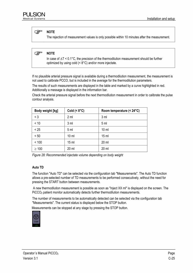
Installation and setup
Operator´s Manual PiCCO2 Page
Version 3.1 C-25
NOTE
The rejection of measurement values is only possible within 10 minutes after the measurement.
NOTE
In case of T < 0.1°C, the precision of the thermodilution measurement should be further
optimized by using cold (< 8°C) and/or more injectate.
If no plausible arterial pressure signal is available during a thermodilution measurement, the measurement is
not used to calibrate PCCO, but is included in the average for the thermodilution parameters.
The results of such measurements are displayed in the table and marked by a curve highlighted in red.
Additionally a message is displayed in the information bar.
Check the arterial pressure signal before the next thermodilution measurement in order to calibrate the pulse
contour analysis.
Body weight [kg] Cold (< 8°C) Room temperature (< 24°C)
< 3 2 ml 3 ml
< 10 3 ml 5 ml
< 25 5 ml 10 ml
< 50 10 ml 15 ml
< 100 15 ml 20 ml
100 20 ml 20 ml
Figure 28: Recommended injectate volume depending on body weight
Auto TD
The function "Auto TD" can be selected via the configuration tab "Measurements". The Auto TD function
allows a pre-selected number of TD measurements to be performed consecutively, without the need for
pressing the START button between measurements.
A new thermodilution measurement is possible as soon as "Inject XX ml" is displayed on the screen. The
PiCCO2 patient monitor automatically detects further thermodilution measurements.
The number of measurements to be automatically detected can be selected via the configuration tab
"Measurements". The current status is displayed below the STOP button.
Measurements can be stopped at any stage by pressing the STOP button.

Installation and setup
Page C-26 Operator’s Manual PiCCO2
Version 3.1
Display of results
The single TD results are displayed in table form. All measurements of one set must be done directly following
each other. The maximum time frame for the measurements is 10 minutes.
Older measurements are displayed in grey and not included in the current average. Active values are
displayed in white. Measurements which are excluded from the average are crossed out.
All active curves can be displayed at a later time by selection. Older measurements are still available in table
form.
Scaling of a thermodilution curve can be changed in two steps by touching the curve.
New in version 3.1: The values for injectate volume (Vinj) and injectate temperature (Tinj) are both displayed
in the thermodilution table.
Quality of a thermodilution measurement:
Figure 29: Thermodilution curve
A normal curve has one smooth peak and then returns in direction to the baseline.
The maximum temperature difference (∆T) should exceed 0.10°C.
The used injectate volume (Vinj), the measured injectate temperature (Tinj) and ∆T can be verified in
the table.
Good measurements within one set of measurements are in close agreement. In case of a dispersion
of CO results of more than 20 %, the measurement is marked with a "?".
Conspicuous measurements have to be rejected.
NOTE
In order to optimize the quality of the thermodilution curve you can use more and/or colder
injectate and inject as rapidly as possible.
Throughout the measurement the patient should remain as still as possible, the position of the
thermodilution catheter must not be moved and no further infusions or injections should be
administered.
CAUTION: Faulty measurements can be caused by incorrectly placed catheters, interfering signal
transmission e.g. of arterial pressure, defective connections or sensors, or by electromagnetic
interference (e.g. electric blankets, electric coagulation).

Installation and setup
Operator´s Manual PiCCO2 Page
Version 3.1 C-27
4 Display Options
(see Figure 12: Screen elements)
The parameter fields on the right, the information bar and the real time pressure curve are displayed
permanently. Extended display options for parameters are accessible in the patient screen.
The default setting provides the basic and commonly used parameters. All necessary modifications and
settings are effected by selecting the respective graphic element.
WARNING: The device enables the monitoring of physiological parameters. The clinical
significance of changes in the monitored parameters must be determined by physician.
4.1 Information bar
Height and weight of patient
Selection takes you to "Patient configuration" screen
Time of last thermodilution measurement
System time
Selection takes you to "Monitor configuration" screen
Loudspeaker
Alarm / warning volume
Blinking: acoustic alarm paused
Not blinking: alarm volume muted
Selection takes you to alarm and volume setting
Battery status
Shows battery status in case system is not connected to mains
Error message (in case of error status)

Installation and setup
Page C-28 Operator’s Manual PiCCO2
Version 3.1
4.2 Real time pressure curve
Figure 30: Real time curve of arterial pressure
Curve and pressure display
Arterial pressure is continuously displayed as pressure curve. The numeric values for heart rate, systolic,
diastolic and mean arterial pressure are displayed.
Systolic marker of arterial pressure
The systolic part of each heart beat is marked by a bar under the curve. If all or some of these bars are
missing, the PiCCO2 cannot analyze the blood pressure curve and thus cannot display results for the
continuous CO.
Selection of the curve on the touch screen directly leads to zero adjustment and scaling of the curve.
CVP value
Central venous pressure of a patient can either be recorded continuously as it is the case with arterial
pressure or it can be entered manually. In the case of manual input the value is displayed in brackets.
Selection of the CVP value on the touch screen displays the continuous CVP curve for 15 seconds.
Selection of the curve leads to zero adjustment. Manual input is done by selection of the CVP value.

Installation and setup
Operator´s Manual PiCCO2 Page
Version 3.1 C-29
4.3 Parameter fields
Figure 31: Parameter fields
The arrangement of the PiCCO2 parameter fields is function-specific. Additionally other parameters can be
configured along side the main parameter of each group.
Selection of the parameter field on the touch screen directly leads to parameter configuration.
NOTE
Discontinuous parameters are marked with the time indicator symbol . The time since
determination of these values is displayed in the information bar on the right hand side.
Depending on the selected measurement function the parameter fields are automatically adapted.

Installation and setup
Page C-30 Operator’s Manual PiCCO2
Version 3.1
4.4 Profiles
Figure 32: "Profiles" screen
Parameter profiles show the measured parameters in respect of their position to the normal value range which
is highlighted.
NOTE
All values displayed in the profile correspond to the time of the last thermodilution measurement.
The option "Overview" shows the main parameters. The organ specific parameters can be displayed by
selection of the respective option.
The marked normal value ranges can be modified. Please contact your PULSION representative to
individually modify the normal values range.

Installation and setup
Operator´s Manual PiCCO2 Page
Version 3.1 C-31
4.5 SpiderVision
The PULSION SpiderVision diagram shows all continuous parameters in dynamic conjunction.
Selection of the SpiderVision diagram on the touch screen directly leads to individual configuration.
The brighter marked areas highlight the normal or target value
for the respective parameter.
The diagram is displayed GREEN as long as all displayed
parameters are within the normal or target value range.
The diagram is displayed YELLOW immediately one of the
displayed parameters goes outside the normal or target value
range.
If the diagram appears RED, two or more displayed
parameters are outside the normal or target value range.
Figure 33: "Spider" screen
All parameters which were given a target value are marked with the target value symbol .
For details concerning the adjustment of normal values to target values please refer to chapter C5.7 Normal
and Target Values.

Installation and setup
Page C-32 Operator’s Manual PiCCO2
Version 3.1
4.6 Trend
Figure 34: "Trend" screen
The number of trends as well as the trend time span of the PiCCO2 parameters can be configured individually.
Selection of a trend curve on the touch screen directly leads to individual configuration.
If more than 4 trends are configured at the same time, the arrow keys on the right side of the screen can be
used for scrolling up or down the trends.
The vertical cursor, which can be activated and moved by the navigation dial, is used for accurate display of
the numeric values at the respective time.
The trend can be displayed numerically or graphically. This selection can be done in the Trend Configuration
screen.

Installation and setup
Operator´s Manual PiCCO2 Page
Version 3.1 C-33
5 Monitor and Display Configuration
The PiCCO2 has a configuration level in order to arrange individual settings. By selecting the respective
function the corresponding option in the configuration menu is opened. A direct change between the single
configuration options is possible.
5.1 Patient settings
Figure 35: "Patient settings" screen
The required settings must be made before starting monitoring. When the PiCCO2 is switched on the device
automatically displays this option.
NOTE
Correct input of height, weight, category and gender is mandatory for the correct indexing of
some parameters.
Selection of height / weight display in the information bar at the top of the screen also opens this option.
The button allows the admission of a new patient. Existing trend information and calibrations will
be erased. The PiCCO2 automatically goes through the next screens which are required.
5.1.1 Information input
Height, Weight 20 – 250 cm / 2 – 300 kg
Input of actual height and weight.
A short-term increase in body weight due to illness (e.g. edema) should be deducted. However, in patients
with pre-existing obesity this weight should be entered.

Installation and setup
Page C-34 Operator’s Manual PiCCO2
Version 3.1
Category adult / pediatric
In marginal cases the decision about the correct category for the individual patient must be based on their
anatomy and appearance (habitus). For further information please refer to chapter E5 Equations for
Calculated Values.
Gender male / female
5.1.2 Predicted body weight
Height, weight, category and gender are needed for the calculation of the Body Surface Area (BSA),
Predicted Body Weight (PBW) and Predicted Body Surface Area (PBSA).
These calculated body characteristics are required for the indexing of PiCCO2 parameters (details see
Appendix, chapter E)
5.2 Monitor settings
Figure 36: "Monitor settings" screen
Settings of date, time, language and further device-related settings.
NOTE
Adjustment of date or time during patient monitoring deletes the complete trend information for
this patient.
Selection of the time or the loudspeaker symbol in the information bar at the top of the screen also opens
this option.

Installation and setup
Operator´s Manual PiCCO2 Page
Version 3.1 C-35
Keytones
The keytones (ON/OFF) are initiated when touching elements on the screen, the device or the navigation dial.
The current setting is retained even if the equipment is switched off.
Alarm
The volume of the acoustic alarm. For safety reasons the settings are adjusted to 75% with every new patient.
Brightness
The selection of brightness of the screen can be done manually. The setting is retained even if the equipment
is switched off.
5.3 Configuration of parameter display
Figure 37: "Parameter configuration" screen
Selection of a parameter field on the right side of the screen directly leads to the configuration screen.
The parameter display can be configured individually. The main parameters are always displayed and cannot
be deselected. Active parameters are displayed in WHITE.
New in version 3.1:
In the “Preload Volume” group, the parameter buttons “SVV” and “PPV” are both displayed and can either be
selected individually, both at the same time, or deselected. Default selection is “SVV”.
In the “Contractility” group, the parameter buttons “GEF” and “CFI” are both displayed and can be selected
individually or deselected. The buttons cannot be selected both at the same time. Default selection is “GEF”.
The parameters are activated or deactivated by selection of the respective parameter button and directly
displayed or disabled in the parameter display.

Installation and setup
Page C-36 Operator’s Manual PiCCO2
Version 3.1
5.3.1 Setting of alarm limits
Adjusting of alarm limits
Alarm limits can be set for the parameters PCCO and ScvO2 . Upper and lower alarm limits have to be
determined. These alarm limits are returned to the default setting with every new patient.
Display alarm limits Yes / No
Display of alarm limits directly next to the respective parameter on the right side of the screen.
5.3.2 PCCI change warning
New in version 3.1:
PCCI warning Off / ± 15 % / ± 25 % / ± 35 %
Warning messages can be displayed when a change in PCCI since the last thermodilution has occurred that
is greater than the threshold value defined in this option. Also, the amount of time elapsed since the last
measurement and the change percentage (e.g. “ΔPCCI ↑ xx%” for positive values or “ΔPCCI ↓ xx%” for
negative values) are alternately displayed in the right part of the information bar (for further information see
chapter 6.2).
The PCCI change warning can be switched off using the “Confirm” button.
The PCCI change warning can be reactivated with a new thermodilution measurement (TD) or by changing
the percentage setting.
Default setting is Off.
The warning message “Significant change - Consider TD” will be displayed, if 80% of the relative change
of PCCI values calculated within the last 2 minutes are above or below the user-defined threshold AND if
the latest TD measurement took place more than 12 minutes ago.
If the PCCI change warning and TD reminder are both activated, the messages in both sections alternate.
Every time a new patient is entered, this setting is automatically reset to the default value Off.

Installation and setup
Operator´s Manual PiCCO2 Page
Version 3.1 C-37
5.3.3 Parameter settings
Absolute / Indexed
Depending on the setting of the entire device the PiCCO2 shows the parameters as either absolute or indexed
to the body characteristics of the patient. Exceptions are the patient profiles, SpiderVision and the trend
display because the indication of normal value ranges is only reasonable for indexed parameters.
Display of units Yes / No
The respective parameter units can be activated or deactivated with this option.
Parameter selection Basic / Cardiac / Septic / Individual
The main parameters are shown in the basic display. In the case of individual parameter settings "Individual"
is displayed.
New in version 3.1:
Two additional settings “Cardiac” and “Septic” are available by default, containing the following parameters:
Cardiac Septic
PCCI, SVI, CI PCCI, SVI, CI
GEDI GEDI, SVV
SVRI SVRI
GEF, dPmx ---
ELWI, CPI, TB ELWI, PVPI, CPI, TB
ScvO2, DO2, VO2 ScvO2, DO2, VO2
Please contact your PULSION representative to individually modify the parameter profiles.

Installation and setup
Page C-38 Operator’s Manual PiCCO2
Version 3.1
5.4 Spider configuration
Figure 38: "Spider configuration" screen
The SpiderVision diagram can be configured individually:
First select the number of spider legs (3 to 7)
Select the parameter to be placed (left)
Select the spider leg where the parameter should be placed
The spider configuration can be opened by direct selection of the spider diagram.
New in version 3.1: The buttons “SVV” and “PPV” are both available for selection.
Parameter selection Basic / Individual
The "Basic" setting uses the default setting of the device which can be recalled at any time.

Installation and setup
Operator´s Manual PiCCO2 Page
Version 3.1 C-39
5.5 Trend configuration
Figure 39: "Trend configuration" screen
The trend display can be configured individually. A maximum of 8 parameter trends can be displayed.
Select the parameter which should be displayed as a trend.
Select the position where the parameter trend should be displayed.
The trend configuration is opened by direct selection of the trend diagram.
New in version 3.1: The buttons “SVV” and “PPV” are both available for selection.
Depending on the selection in the “Parameters” configuration tab, either the “GEF” or the “CFI” button is
displayed, respectively. If neither of the buttons is selected, the “GEF” button is displayed.
Display Graphic / Numeric
The trend display of individual parameters can be graphic or numeric.
Time span 10min / 1h / 6h / 24h / 2d / 6d / 12d
Time span of trend display.
Parameter selection Basic / Individual
The "Basic" setting uses the default setting of the device which can be recalled at any time.

Installation and setup
Page C-40 Operator’s Manual PiCCO2
Version 3.1
5.6 Measurement configuration
Figure 40: "Measurement configuration" screen
The measurement configuration can be directly accessed from the respective measurement screen.
5.6.1 Configuration of thermodilution measurement
Art. Catheter
Automatic detection and display of the connected thermodilution catheter. If a new PiCCO catheter type is not
automatically recognized by the device, it is necessary to enter the ACC (Arterial Catheter Constant, indicated
on the connector of the PiCCO catheter).
Position A. Axillaris / A. Brachialis / A. Femoralis / A. Radialis
The intended catheter position is displayed and can be changed if necessary.
Auto Thermodilution Mode (Auto TD) Off / 3x / 4x / 5x
The number of TD measurements can be set automatically. The device will prompt the user to inject without
the need to press the START button repeatedly.
Default setting is 3x.
New in version 3.1: The selected value remains valid for every new patient.
TD Reminder Off / 1h / 2h / 4h / 8h
Setting of the individual reminder to perform a thermodilution measurement. Default setting is 8h.
New in version 3.1: When the selected TD reminder time has elapsed, the message “TD Measurement
recommended” and the amount of time elapsed since the last measurement are displayed in the information
bar (see also chapter 6.2).
The selected value remains valid for every new patient.

Installation and setup
Operator´s Manual PiCCO2 Page
Version 3.1 C-41
5.6.2 Configuration of central venous catheter
Setting of the individual injection site and injectate volume for the central venous catheter.
New in version 3.1:
Inj. Site: V. Jug./Subcl. / V. Femoralis
Selection of the injection site. Default setting is V. Jug./Subcl.
Inj. Volume: 2ml / 3ml / 5ml / 10ml / 15ml / 20ml
Setting of the individually required injectate volume. The recommended injectate volume will be displayed
depending on body weight of the patient (see also Figure 40: "Measurement configuration" screen). Default
setting for an adult patient is 15ml.
5.6.3 Configuration of ScvO2 measurement
Hb / Hct Hb / Hct
Optional input of Hb or Hct. Default setting is Hb.
Hb Unit g/dl / mmol/l
Input of Hb can be made in the preferred unit. Default setting is g/dl.
5.6.4 Configuration of ICG measurement
The ICG measurement option only appears if a LiMON module is connected.
ICG Dose 0.25mg/kg / 0.5mg/kg
Default setting is 0.5mg/kg
ICG quantity mg
The necessary quantity of ICG, dependent on the settings and the patient´s body weight. The calculated value
may not be altered.

Installation and setup
Page C-42 Operator’s Manual PiCCO2
Version 3.1
5.7 Normal and Target Values
The allocation of target values is accessible via the menu "Normal values" of the help function or the
parameter configuration. When pressing the "Adjust" button, a screen opens with a list of normal parameter
values.
Figure 41: Normal- / Target value range
Adjustment of normal values to target values in the selection field is necessary in order to define target values.
The allocation of target values applies for all display screens (Spider, Trends and Profile).
In the SpiderVision diagram the target value symbol is displayed next to the respective parameter, if the target
value is activated.
In order to restore normal values in the target selection press the button. All changes
made will be cancelled and the default setting (normal values) will be restored.
When admitting a new patient normal values are automatically used.
New in version 3.1: The buttons “SVV” and “PPV” are both available for selection.
Depending on the selection in the “Parameters” configuration tab, either the “GEF” or the “CFI” button is
displayed, respectively. If neither of the buttons is selected, the “GEF” button is displayed.

Installation and setup
Operator´s Manual PiCCO2 Page
Version 3.1 C-43
6 Alarms, messages and troubleshooting
The PiCCO2 displays alarms, warnings and additional important information with different priorities.
Categories:
Priority Meaning Display
1 Alarm: Emergency, immediate
response necessary
Red blinking text display, acoustic
alarm, blinking LEDs
2 Error messages, response necessary Yellow text display
3 Additional information Grey text display
Messages with the same priority are displayed alternately.
Setting of acoustic alarm:
Selection of the loudspeaker symbol directly leads to setting of the alarm volume.
The volume and the status of the acoustic alarm are displayed on the right side of the information bar.
Alarm muted (2 min / 5 min)
Blinking
Alarm volume, 6 steps Turned down
Loud
Alarm turned off
No acoustic alarm
Suppression of acoustic alarm
The acoustic alarm can be temporarily paused. As long as the alarm condition exists the acoustic alarm can
be heard again after:
2 minutes in case of parameter alarm
5 minutes in case of battery alarm
WARNING: Before using the device the setting of the alarm limits and the alarm volume must be
checked for their suitability for the respective patient.
If an alarm condition arises while the alarm is suppressed, only the optical warning will be given.

Installation and setup
Page C-44 Operator’s Manual PiCCO2
Version 3.1
6.1 Alarms
Alarms are displayed with priority 1, error messages with lower priority are overridden.
Alarm Cause Remedy
High PCCO / PCCI PCCO / PCCI > alarm limit -
Low PCCO / PCCI PCCO / PCCI < alarm limit -
High ScvO2 ScvO2 > alarm limit -
Low ScvO2 ScvO2 < alarm limit -
High SpO2 SpO2 > alarm limit -
Low SpO2 SpO2 < alarm limit -
Low Battery Battery status < 25% and
device is not connected to
mains power
Connect device to mains power
Internal error -
restart the device or
SERVICE
No signals longer than 10 s
(e.g. internal USB does not
work)
Restart the device, if error exists
further on, SERVICE necessary
Internal error -
SERVICE necessary
Internal error SERVICE necessary
6.2 Error Messages
Text error messages are displayed in the information bar (chapter C4.1). When viewing old measurements the
respective error messages are displayed as well.
General
Error Message Cause Remedy
Enter patient data for
indexed values
Patient data (height / weight) etc. not
entered
Enter patient data.
Thermodilution
Error Message Cause Remedy
Invalid / Faulty catheter - Change
catheter
Faulty catheter, not
compatible or not connected
Connect compatible
catheter
Unknown catheter - Enter ACC Unknown catheter type with
unknown resistor
Enter ACC in
corresponding field
Injection Error - Repeat injection,
rapid and smooth
Injection not smooth Repeat injection rapidly
and smoothly
Injectate Temp. Sensor Error -
Check sensor cable and sensor
housing
Defective injectate temp.
sensor or sensor cable
Check and replace if
necessary

Installation and setup
Operator´s Manual PiCCO2 Page
Version 3.1 C-45
Injection Error - Inject faster than
10 s
Time of injection longer than
10 seconds
Repeat injection rapidly
and smoothly
TD Curve Error - Stabilize patient
temperature and repeat injection
Calculation error of MTt / DSt
caused by temperature
interferences
Eliminate interference and
repeat injection
Baseline Error - Stabilize patient
temperature and repeat injection
Large temperature variations
detected
Eliminate temperature
variations and repeat
injection
Time Out - Repeat fast injection
with cold injectate
Thermodilution curve not
finished within 90 seconds,
possibly very high EVLW with
low CO
Repeat injection with cold
and/or more injectate, if
necessary stabilize
patient
Error: Injectate too warm Injectate temperature above
blood temperature
Use colder injectate
(< 24°C)
Warning: Injectate too warm Tinj > 26 °C Use colder injectate
(< 24°C)
ΔT small - Use more and/or
colder injectate
∆T < 0.1 °C Use more and/or colder
injectate
Invalid PCCO Calibration - Check
AP signal and repeat injection
Implausible arterial pressure
signal, signal interferences
Eliminate possible
interferences and repeat
injection
ScvO2 Measurement and Calibration
Error Message Cause Remedy
ScvO2 Calibration Error - Check
optical module and probe
Defective module, probe or
connections
Check module and probe,
if necessary replace and
repeat calibration
Signal too high -
Check probe and position
Artifact due to vessel wall
contact of probe
Check probe, if necessary
relocate and repeat
calibration
Signal too low -
Check probe and position
Probe or module damaged,
defective connector
Check probe, if necessary
replace it and repeat
calibration
Too much ambient light - Check
optical module
Optical module damaged,
defective connector
Check module, if
necessary replace it and
repeat calibration. Avoid
too much ambient light.
Optical module disconnected -
Check optical module and probe
connections
Optical module not
connected
Connect optical module

Installation and setup
Page C-46 Operator’s Manual PiCCO2
Version 3.1
Implausible ScvO2 value -
Recalibrate the monitor
Implausible value due to
defect or interference
Check probe, position and
optical module and repeat
calibration.
Error Optical Module -
Check/Replace optical module
Internal electronic problem in
optical module
If necessary replace
optical module
SpO2 / PDR
Error Message Cause Remedy
Error LiMON Sensor - Check /
Exchange LiMON sensor
Sensor error
(for more than 5 seconds)
Use a compatible and
correctly functioning
sensor
Error LiMON Module - Check /
Exchange LiMON module
Module error
(for more than 5 seconds)
Use a compatible and
correctly functioning
module
Error LiMON Sensor - Connect
LiMON sensor
Sensor not connected to
device or patient
(for more than 5 seconds)
Check connection of the
sensor
Pulse not detected - Relocate
LiMON sensor
Insufficient pulse signal
(for more than 5 seconds)
Reposition the sensor to a
place with better perfusion
Bad signal quality – Relocate
LiMON sensor
Insufficient pulse signal
(for more than 5 seconds)
Reposition the sensor to a
place with better perfusion
Too much ambient light – relocate
or cover LiMON sensor
Too much ambient light
(for more than 5 seconds)
Cover the sensor with
dark or non-transparent
material. Employ a
different sensor location
better protected from
ambient light
Strong movement artefacts –
reduce LiMON sensor movement
Too much movement
(for more than 5 seconds)
Avoid patient movement
LiMON module disconnected –
Check module connection
Module not connected to
device or patient
Check connection of the
module
Bad signal quality – Check signal
and repeat measurement
Low rate of perfusion Relocate the sensor,
repeat the measurement

Installation and setup
Operator´s Manual PiCCO2 Page
Version 3.1 C-47
6.3 Additional information
Helpful additional and status information are also displayed in the information bar after performed or expected
action.
Message / Display Is displayed at following actions
Print key
Printout in process Press print key
Printout ready After printout is completed
USB device detected After detection of a USB device
No USB device detected Pressing the print button and no USB device is
connected or detected
Printer error - Check printer No paper or printer cartridge, paper jam
Real Time Pressure
No continuous CVP available Touching the CVP parameter field and when
continuous CVP not available
Thermodilution
Thermodilution in progress. Press “STOP”
to cancel the thermodilution
Request another action during thermodilution
Measurement is rejected. Not included in
average
Reject a TD measurement
Measurement included in average Selection of an active TD measurement
TD Measurement recommended TD reminder limit is reached
Significant change – Consider TD PCCI above selected threshold
ScvO2 Calibration
Draw blood sample and confirm Request ScvO2 calibration screen
Please enter ScvO2/Hb lab values Request ScvO2 calibration screen
Outside of ScvO2 calibration screen as long as lab
values are not entered
Incorrect / Implausible Input Input incorrect / not plausible
PDR
Measurement in progress - Press „STOP“ to
cancel Request another action during PDR measurement
ICG influence: CAL not possible, please
wait
Remaining ICG concentration in the blood too high
Sensor not connected – Connect LiMON
sensor Sensor not connected; pressing of (greyed) ICG button
Zero adjustment
Zero adjustment failed - Pressure unstable Unstable pressure (>2 mmHg/s) during zero
adjustment

Installation and setup
Page C-48 Operator’s Manual PiCCO2
Version 3.1
Zero adjustment failed - Close stopcock Unstable pressure (>5 mmHg/s) during zero
adjustment
Zero adjustment of AP successful Pressing AP >0< button
Zero adjustment of CVP successful Pressing CVP >0< button
Zero adjustment of PAP successful Pressing PAP >0< button
Zero adjustment necessary No initial zero adjustment of AP and CVP
Trend
Move white marker by turning the
navigation dial
Request TREND screen

Installation and setup
Operator´s Manual PiCCO2 Page
Version 3.1 C-49
7 Help Functions
The help function offers information relating to installation and operation. It can be accessed during monitoring
by pressing the key. Furthermore, information on monitor status (software or hardware version) can be
obtained.
Components:
Setup: Setup Guide PiCCO2 (see Figure 16)
Normal Values/Target Values: This tab details the normal value ranges / target value ranges of the
individual values.
New in version 3.1: Detailed “Parameter Explanations” are available for each of the framed
parameter areas. The corresponding screen can be accessed by touching the respective area.
Decision Model
Physiological Overview
Info: System information

Installation and setup
Page C-50 Operator’s Manual PiCCO2
Version 3.1
8 Printout
For documentation purposes the PiCCO2 results can be printed.
8.1 USB Virtual Printing Option
By means of an optional PULSION USB Memory Stick (MPI78), a PDF file is generated and automatically
stored on the USB Memory Stick when pressing the "Print key" on the device.
In doing so a file folder with the current date is automatically generated and the file with the time as file name
is stored. The USB virtual printing option offers three different printing formats:
Basic: The main parameters which are shown in the basic display are always printed.
Additional parameters are printed according to the settings made in the parameter
configuration screen.
Trend: When pressing the "Print key" while the trend screen is displayed, the printout includes
the trend curves that have been selected in the trend configuration screen.
Thermodilution: When pressing the "Print key" while the thermodilution screen is displayed,
the printout includes a table with the results of the last thermodilution
measurements as well as the respective curves. Messages that ocurred during a
particular TD measurement are displayed on the respective curve of the printout.
New in version 3.1: In addition to the printout, a screenshot of the current screen is stored in JPG format in a
separate “Screenshots” folder. The file has the same timestamp as the corresponding PDF file.
8.2 Label Printer
By means of the optional PULSION Printer (PC85300) a printout can be made for filing or placing into the
patient file.
The printer is connected at the USB port on the back of the PiCCO2 and it is recognized automatically when
starting the monitor.
All parameters which are selected in the parameter configuration screen will be printed on the label.
For information relating to replacement of printer cartridge and paper, please consult the accompanying
instruction for use.

Installation and setup
Operator´s Manual PiCCO2 Page
Version 3.1 C-51
9 Battery Function
The device is equipped with a battery to ensure the maintenance of operations for at least 30 minutes without
mains power supply.
The PiCCO2 must be connected to the mains power supply for at least 6 hours in order to completely charge
the battery.
In order to maintain the charging condition of the battery, the device must remain on mains power supply
during storage and the main switch at the back of the device must remain on position “ON”.
The battery symbol in the information bar shows the current state of charge:
Battery charging Grey, last bar of status display is blinking
Fully charged, device connected to
mains power
No battery symbol
Battery-powered, > 25% capacity Grey, remaining capacity in 25% steps
Battery-powered, < 25% capacity
Red, blinking with acoustic alarm
No battery in device
Grey, crossed out symbol
In cases of a battery alarm the acoustic alarm can be paused for 5 minutes.
NOTE
If the operating time of the fully charged battery drops below 30 minutes, or the remaining
operating time after the battery alarm has started (a red blinking battery symbol) drops below 7
minutes, contact your PULSION representative to replace the internal battery.
Ensure that the batteries are disposed of correctly after expiration of battery life.
NOTE
In case of a totally discharged battery the message “Battery totally discharged” appears on the
screen. To ensure a fully charged battery, the device must be connected to mains power supply
for up to 24 hours.
CAUTION: Check the battery state of charge when using the device. Only when the battery is fully
charged, the use of the device can be ensured for the stated time without being connected to the
mains.

Installation and setup
Page C-52 Operator’s Manual PiCCO2
Version 3.1
10 Cleaning and Disinfection
For cleaning and disinfecting the PiCCO2 patient monitor only PULSION approved substances and methods
listed in this chapter may be used. PULSION makes no claims regarding the efficacy of the listed chemicals or
methods as a means of controlling infection. Please consult your hospital´s Infection Control Officer or
Epidemiologist.
10.1 General remarks
Keep the monitor, cables and accessories free of dust and dirt. After cleaning and disinfection, carefully check
the equipment.
Do not use the equipment if signs of deterioration or damage are visible. If you need to return any of the
equipment to PULSION, decontaminate it first.
10.2 Precautions
Please observe the following precautions:
Do not sterilize the monitor, related products, accessories or supplies by steam, heat, radiation or
ETO unless otherwise indicated in the instructions for use accompanying the accessories and
supplies.
Always dilute the used substances according to the manufacturer´s instructions or use the lowest
possible concentration.
Take care that no liquid enters the PiCCO2 case.
Do not allow cleaning or disinfecting agents to remain on any of the equipment surfaces. Remove
them immediately with a cloth dampened with water and dry with a clean cloth.
Do not use abrasive material (e.g. steel wool or silver polish) or sharp objects (e.g. needles, paper
clips, etc.) to clean the PiCCO2.
Never use bleach.
Before starting, turn off the PiCCO2 and disconnect the mains power connection cable from the
mains receptacle.
WARNING: Do not reconnect the PiCCO2 to electrical power if liquid has entered the device. A
short circuit may damage the device and cause hazardous conditions for patient and user.
Allow disinfectants to evaporate for at least 15 minutes before the device is switched on again.
CAUTION: Never place the cables in water or other cleaning solutions. The cables and
connections are not water-tight. Never sterilize the cables by radiation, steam or gas.
Do not use abrasive or sharp-edged tools to clean the optical module as this may damage or
destroy optical components.

Installation and setup
Operator´s Manual PiCCO2 Page
Version 3.1 C-53
10.3 Cleaning
When cleaning the PiCCO2, please proceed as follows:
Clean the surface of the PiCCO2 with a soft, lint-free cloth moistened with warm water (40°C/104°F
maximum) and soap, a diluted non-caustic detergent, tenside, ammonia- or alcohol-based cleaning
agent.
Do not use strong solvents.
Take special care when cleaning the touch screen of the PiCCO2 as it is more sensitive to rough
cleaning methods than the housing.
Do not allow water or cleaning solution to enter the connectors of the monitor.
Recommended cleaning agents:
Tensides Edisonite Schnellreiniger®
Ammonias Dilution of Ammonia < 3%, Window Cleaner
Alcohol Ethanol 70%, Isopropanol 70%
10.4 Disinfection
Disinfect the product as stated by your hospital´s policy in order to avoid long-term damages.
Before disinfection clean the equipment.
CAUTION: Do not mix disinfecting solutions (such as bleach and ammonia) as hazardous gases
may be the result.
Recommended disinfecting agents:
Alcohol based: Ethanol 70%, Isopropanol 70%, Cutasept®, Kodan®, Sagrosept®, Sterilium Fluid®
Aldehyde: Cidex®

Installation and setup
Page C-54 Operator’s Manual PiCCO2
Version 3.1
- Blank page -

Disposables / Accessories
Operator´s Manual PiCCO2 Page
Version 3.1 D-1
D Disposables / Accessories
1 Disposables
WARNING: For safety of operation and for accuracy of measurements, only disposables and
accessories approved by PULSION Medical Systems may be used with the PiCCO2.
Reuse of disposable items is not allowed. Re-sterilization of disposables may cause infections in
the patient.
Technical specifications are subject to change without further notice.
1.1 PiCCO Catheter (arterial thermodilution catheter)
The PiCCO catheters are specifically designed thermodilution catheters for use with the PiCCO2.. Every
catheter has a built-in thermistor and a distal lumen for arterial pressure measurement.
PV2013L07-A / PV2013L07N / PV2013L07
3F thermodilution catheter with a usable length of 7 cm and a distal lumen, 20/22 G cannula, guide wire.
PV2014L08-A / PV2014L08N / PV2014L08
4F thermodilution catheter with a usable length of 8 cm and a distal lumen, 20 G cannula, "J" guide wire,
vessel dilator.
PV2014L16-A / PV2014L16N / PV2014L16
4F thermodilution catheter with a usable length of 16 cm and a distal lumen, 18/20 G cannula, "J" guide wire,
vessel dilator.
PV2014L22-A / PV2014L22N / PV2014L22
4F thermodilution catheter with a usable length of 22 cm and a distal lumen, 18/20 G cannula, guide wire,
vessel dilator.
PV2015L20-A / PV2015L20N / PV2015L20
5F thermodilution catheter with a usable length of 20 cm and a distal lumen, 18/20 G cannula, "J" guide wire,
vessel dilator.
PV2014L50LGW-A / PV2014L50LGWN / PV2014L50LGW
4F thermodilution catheter with a usable length of 50 cm and a distal lumen, 22G/20G cannula, guide wire.
NOTE
Single packed guide wires are available for all catheters.
Consult accompanying instructions for use of disposables and accessories.

Disposables / Accessories
Page D-2 Operator’s Manual PiCCO2
Version 3.1
WARNING: When placing the arterial catheter into a large artery (e.g. femoral, brachial or axillary
artery) do not advance the tip of the catheter into the aorta.
An intracardiac blood pressure measurement is not allowed. This means that the measuring
position (catheter tip) must not be directly in the heart.
Reuse of disposable items is not allowed. Re-sterilization of disposables may cause infections in
the patient.
1.2 PiCCO Monitoring Kits
The PV8115 / PV8215 monitoring kits (for arterial pressure) contain:
pressure transducer with macro set, spike, line lock and flush device (flow rate 3 ml/h)
3-way-stopcock, injectate temperature sensor housing (PV4046)
150 cm red pressure line
The PV8115CVP / PV8215CVP monitoring kits (for central venous pressure or arterial pressure) contain:
pressure transducer with macro set, spike, line lock and flush device (flow rate 3 ml/h)
3-way-stopcock, injectate temperature sensor housing (PV4046)
150 cm blue pressure line
150 cm red pressure line
1.3 Injectate Temperature Sensor Housing
The injectate temperature sensor housing PV4046 is required to determine the injection temperature during
thermodilution measurements.
Single packed PV4046 are also available.

Disposables / Accessories
Operator´s Manual PiCCO2 Page
Version 3.1 D-3
1.4 CeVOX probe
The PULSION CeVOX fiberoptic probes have been specifically developed for use with the PULSION optical
module. The probes are equipped with fiberoptics to transfer light at a specific wavelength. For continuous
oxygen saturation monitoring the probe is inserted into the distal lumen of an already placed central venous
catheter. Dependent on the type of the central venous catheter an appropriate probe has to be selected.
PV2022-30 2F CeVOX probe (usable length: 30 cm)
PV2022-32 2F CeVOX probe (usable length: 32 cm)
PV2022-33 2F CeVOX probe (usable length: 33 cm)
PV2022-35 2F CeVOX probe (usable length: 35 cm)
PV2022-37 2F CeVOX probe (usable length: 37 cm)
PV2022-38 2F CeVOX probe (usable length: 38 cm)
PV2022-48 2F CeVOX probe (usable length: 48 cm)
Other lengths can be ordered with a delivery time of 6 weeks (packaging unit=50).
The CeVOX probes are designed for 15 cm, 20 cm and 30 cm central venous catheters with a distal lumen of
ø ≥ 0.032´´ guide wires (0.8 mm). The tip of the probe has to exceed the distal tip of the central venous
catheter by 2.5 ± 0.5 cm.
WARNING: Incorrect use of the ScvO2 probe can lead to vessel perforation. Therefore check the
correct position of the probe as indicated in the probe´s instructions for use.

Disposables / Accessories
Page D-4 Operator’s Manual PiCCO2
Version 3.1
2 Accessories
Article number Description
PC8500 PiCCO2 Monitor
PC80150 Arterial connection cable and injectate temperature interface cable
PC80109 Injectate sensor cable
PMK-206 Pressure connection cable
PC85200 PiCCO2 AUX Adapter
401090 Mains power cable (240V)
401080 Potential equalization cable
PC3010 / PC3015 CeVOX module
PC5100 LiMON module
PC51100 LiMON Reusable Sensor, large
PC51200 LiMON Reusable Sensor, medium
PC51300 LiMON Reusable Sensor, small
PC85300 PiCCO2 Thermotransfer printer
PC85350 Printer labels (565 labels per roll)
PC85355 Thermo-transfer ink ribbon
PC85230 PiCCO2 cart
PC85231 Basket for cart
PC85232 Anchoring clip
PC85233 PiCCO2 variable wall mounting arm for horizontal standard bar
PC856EN PiCCO2 Operator´s Manual English
CAUTION: Do not pull on the probes or cables in order to remove them from the device. Observe
the instructions for use for the probes in order to ensure that a technically correct procedure is
carried out.

Appendix
Operator´s Manual PiCCO2 Page
Version 3.1 E-1
E Appendix
1 Technical Data
General
Equipment PiCCO2
Article number PC8500
Equipment Class IIb
Equipment Type Type BF: ScvO2;
Type CF: CO, AP, CVP;
all defibrillation-proof
Protection Class: I
Accessories
PiCCO catheter and kits Please consult accompanying instructions for use of
the PiCCO catheter
Arterial connection cable and injectate temperature
interface cable
Art. No.: PC80150
Injectate temperature sensor cable Art. No.: PC80109
Pressure cable Art. No.: PMK-206
PiCCO2 AUX Adapter Art. No.: PC85200
Mains power cable Art. No.: 40109X (dependent on country)
Grounding cable Art. No.: 401080
CeVOX module Art. No.: PC3010 / PC3015
LiMON module Art. No.: PC5100
Screen
Type 13.3" (=338 mm) TFT LCD colour display, touch
screen, active matrix
Size (W x H) 299 x 195 mm
Viewing Area (W x H) 286 x 178 mm
Resolution 1280 x 800 Pixel
Electrical Specifications
Mains Voltage 100 to 240 VAC
Mains Frequency 50 to 60 Hz
Power Consumption 85 VA
Internal Battery 14.4V 36Wh
Cell Type Lithium-Ion
Charging Time 3-5h

Appendix
Page E-2 Operator’s Manual PiCCO2
Version 3.1
Battery Operating Time > 30min
Operating Conditions
Temperature Range 10 °C to 40 °C (50 °F to 104 °F)
Relative Humidity 75% (non-condensing)
Ambient Pressure 700 hPa to 1060 hPa
Transport and Storage Conditions
Temperature Range -20 to 60°C (-4°F to 140°F), (with rechargeable
battery -20 to 50°C (-4°F to 122°F))
Relative Humidity 90% (non-condensing)
Ambient Pressure (Storage) 700 hPa to 1060 hPa
Ambient Pressure (Transport) 270 hPa to 1060 hPa
Physical Attributes
Size (W x H x D) 328 mm x 248 mm x 180 mm (with navigation dial)
Weight < 5 kg
Standards
EN 60601-1:1990 + A1:1993 + A2:1995
EN 60601-1-1:2001, EN 60601-1-2:2007, EN 60601-1-4:1996 +A1:1999, EN 60601-1-6:2007,
EN 60601-1-8:2007, EN 60601-2-34:2000
PiCCO2 complies with directive 93/42/EEC (medical products) and bears the CE mark
User Interface
User Controls Touch screen
Navigation dial
Function keys
Data Transmission Capabilities
Interfaces RS232
LAN
2xUSB
Printer USB

Appendix
Operator´s Manual PiCCO2 Page
Version 3.1 E-3
Measured Parameters:
Label Unit Lower limit Upper limit Accuracy
PCCO l/min 0.25 25.0 Coefficient of variation ≤ 2 %*
SV ml 1 250 Coefficient of variation ≤ 2 %*
CO l/min 0.25 25.0 Coefficient of variation ≤ 2 %*
GEDV ml 40 4800 Coefficient of variation ≤ 3 %*
ITBV ml 50 6000 Coefficient of variation ≤ 3 %*
EVLW ml 10 5000 Coefficient of variation ≤ 6 %*
ScvO2 % 1 99 ±3 % for 50 – 80 %
SpO2 % 45 100 70% < SpO2 < 100%: ≤ 2 %
SpO2 < 70% not validated
PDR %/min 0.0 50.0 ±3 % / min (absolute) or 15 % relative
R15 % 0.0 99.9 n.a.
TB °C 25 45 ±0,1 °C
Tinj °C 0 30 ±0,1 °C
AP mmHg 0 300 ±4 mmHg (absolute) or 4 % relative
(acc. to EN 60601-2-34: 2000)
CVP mmHg -10 50 ±4 mmHg (absolute) or 4 % relative
(acc. to EN 60601-2-34: 2000)
*Coefficient of variation, measured using synthetic and/or database wave forms (laboratory testing)
Technical specifications are subject to change without further notice.

Appendix
Page E-4 Operator’s Manual PiCCO2
Version 3.1
2 Maintenance and Service
2.1 Classification
This product is classified according to Council Directive 93/42/EEC of 14 June 1993 concerning medical
devices, annex IX:
Class II b
2.2 Maintenance
Before commencing monitoring of a patient, check the PiCCO2 for any mechanical damage, check all input
cables, connectors and accessories and check all functions necessary for patient monitoring.
The PULSION PiCCO2 and its accessories are maintenance free and are not subject to special intervals of
service if local medical law does not indicate this. For further details about potential difficulties, possible
causes and suggested remedies see chapter C6.2.
CAUTION: If the PiCCO2 appears to be damaged, contact your local PULSION representative. Do
not use the PiCCO2 if the device appears to be damaged. If the system check detects a failure, no
function will be available and “SERVICE” is displayed on the screen. Turn the PiCCO2 off and
contact your local PULSION representative. Do not attempt to use or repair the PiCCO2.
IMPORTANT
Updates and all checks which require the PiCCO2 to be opened must be made by a PULSION
technician.
For telephone inquiries relating to service, technical support, accessories or other matters contact
PULSION Medical Systems SE.
To respond to questions, PULSION Medical Systems SE will need the serial number of the device
that is found on the rear panel of the PiCCO2.
PULSION Medical Systems SE
Hans-Riedl-Str. 17
D-85622 Feldkirchen
Germany
Phone: +49 – (0)89 – 45 99 14 – 0
Fax +49 - (0)89 - 45 99 14 – 18
E-mail: [email protected]
Internet: www.PULSION.com

Appendix
Operator´s Manual PiCCO2 Page
Version 3.1 E-5
2.3 Disposal of electrical and electronic equipment
The 2012/19/EU Directive aims to increase the separate collection, reuse, recovery and recycling of waste
from electrical and electronic equipment. This directive applies to all electrical and electronic appliances as
well as to medical devices.
As a medical device, the PiCCO2 is subject to this directive and is labelled with the symbol of the
crossed-out wheeled bin.
NOTE
Ensure that the included lithium-ion battery is removed from the device and disposed of correctly.

Appendix
Page E-6 Operator’s Manual PiCCO2
Version 3.1
3 Interfaces
AP / CVP
Transfer of continuous arterial pressure (AP) and central venous pressure (CVP) signal to bedside monitor.
LAN
Connection for network devices for printing and data transfer.
Serial Interface RS232
Connection for patient data management systems (PDMS)
Please contact your PULSION representative for current technical information.
USB ports (2)
Connection for external printer and PULSION memory stick.
The interfaces are galvanically isolated by an isolation voltage of 1.5kV (IEC 60601-1).
CAUTION: Furthermore, all configurations have to meet the system standard IEC 60601-1-1.
Any person who connects additional devices to the signal input or signal output of the PiCCO2 is
changing the system configuration and is responsible for observing the requirements of the
IEC 60601-1-1 Standard.
IMPORTANT: For safety of operation, only memory sticks and printers approved by
PULSION Medical Systems may be used with the PiCCO2.

Appendix
Operator´s Manual PiCCO2 Page
Version 3.1 E-7
4 EMC-Requirements
Table 1 – Guidance and manufacturer´s declaration – electromagnetic emissions
(EN 60601-1-2:2007; 5.2.2.1 c)
Guidance and manufacturer´s declaration – electromagnetic emissions
The PiCCO2 is intended for use in the electromagnetic environment specified below. The customer or the user of the
PiCCO2 should assure that it is used in such an environment.
Emissions test Compliance Electromagnetic environment - guidance
RF emissions
CISPR 11 Group 1
The PiCCO2 uses RF energy only for its internal
function. Therefore, its RF emissions are very low and
are not likely to cause any interference in nearby
electronic equipment.
RF emissions
CISPR 11 Class B
The PiCCO2 is suitable for use in all establishments,
including domestic establishments and those directly
connected to the public low voltage power supply
network that supplies buildings used for domestic
purposes.
Harmonic emissions
IEC61000-3-2 Class A
Voltage fluctuations /
flicker emissions
IEC 61000-3-3
Complies

Appendix
Page E-8 Operator’s Manual PiCCO2
Version 3.1
Table 2 – Guidance and manufacturer´s declaration – electromagnetic immunity
(EN 60601-1-2:2007; 5.2.2.1 f)
Guidance and manufacturer's declaration - electromagnetic immunity
The PiCCO2 is intended for use in the electromagnetic environment specified below. The customer or the user of the PiCCO2 should assure that it is used in such an environment.
Immunity test IEC 60601 test level Compliance level Electromagnetic environment - guidance
Electrostatic
discharge (ESD)
IEC 61000-4-2
± 6 kV contact
± 8 kV air
± 6 kV contact
± 8 kV air
Floors should be wood, concrete or ceramic tile. If floors are covered with synthetic material, the relative humidity should be at least 30%.
Electrical fast transient / burst
IEC 61000-4-4
± 2 kV for power supply lines
± 1 kV for input / output
lines
± 2 kV for power supply lines
± 1 kV for input / output lines
Mains power quality should be that of a typical commercial or hospital environment.
Surge
IEC 61000-4-5
± 1 kV line(s) to line(s)
± 2 kV line(s) to earth
± 1 kV line(s) to line(s)
± 2 kV line(s) to earth
Mains power quality should be that of a typical commercial or hospital environment.
Voltage dips, short interruptions and voltage variations
on power supply
input lines IEC 61000-4-11
< 5% UT
(>95 % dip in UT)
for 0,5 cycle
< 5% UT
(>95 % dip in UT)
for 0,5 cycle
Mains power quality should be that of a typical commercial or hospital environment. If the user of the PiCCO2 requires continued Operation during power mains interruptions, it is recommended that the PiCCO2 is powered from an uninterruptible power supply or a battery.
40% UT
(60 % dip in UT)
for 5 cycles
40% UT
(60 % dip in UT)
for 5 cycles
70% UT
(30 % dip in UT)
for 25 cycles
70% UT
(30 % dip in UT)
for 25 cycles
< 5% UT
(> 95% dip in UT)
for 5 s
< 5% UT
(> 95% dip in UT)
for 5 s
Power frequency
(50/60 Hz)
magnetic field
IEC 61000-4-8
3 A/m 3 A/m Power frequency magnetic fields should be at levels characteristic of a typical location in a typical commercial or hospital environment.
NOTE UT is the a.c. mains voltage prior to application of the test level.

Appendix
Operator´s Manual PiCCO2 Page
Version 3.1 E-9
Table 3 – Guidance and manufacturer´s declaration – electromagnetic immunity
(EN 60601-1-2:2007; 5.2.2.2)
Guidance and manufacturer's declaration - electromagnetic immunity
The PiCCO2 is intended for use in the electromagnetic environment specified below. The customer or the user of the PiCCO2 should assure that it is used in such an environment.
Immunity test IEC 60601 test level Compliance level
Electromagnetic environment - guidance
Conducted RF
IEC 61000-4-6
Radiated RF
IEC 61000-4-3
3 Vrms
150 kHz to 80 MHz
3 V/m
80 MHz to 2.5 GHz
3 Vrms
3 V/m
Portable and mobile RF communications
equipment should be used no closer to any part of
PiCCO2, including cables, than the recommended
separation distance calculated from the equation
applicable to the frequency of the transmitter.
Recommended separation distance:
d = 1.17 1/V * P
d = 1.17 m/V * P for 80 MHz to 800 MHz
d = 2,33 m/V * P for 800 MHz to 2,5 GHz
where P is the maximum output power rating of
the transmitter in watts (W) according to the
transmitter manufacturer and d is the
recommended separation distance in meters (m).
Field strength from fixed RF transmitters, as
determined by an electromagnetic site survey,a
should be less than the compliance level in each
frequency range.b
Interference may occur in the vicinity of
equipment marked with the following symbol:
NOTE 1 At 80 MHz and 800 MHz, the higher frequency applies.
NOTE 2 These guidelines may not apply in all situations. Electromagnetic propagation is affected by absorption and reflection of structures, objects and people.
a Field strengths from fixed transmitters, such as base stations for radio (cellular/cordless) telephones and land
mobile radios, amateur radio, AM and FM radio broadcast and TV broadcast cannot be predicted theoretically with accuracy. To assess the electromagnetic environment due to fixed RF transmitters, an electromagnetic site survey should be considered. If the measured field strength in the location in which the PiCCO2 is used exceeds the applicable RF compliance level above, the PiCCO2 should be observed to verify normal operation. If abnormal performance is observed, additional measures may be necessary, such as reorienting or relocating the PiCCO2.
b Over the frequency range 150 kHz to 80 MHz, field strength should be less than 3 V/m.

Appendix
Page E-10 Operator’s Manual PiCCO2
Version 3.1
Table 6 – Recommended separation distances between portable and mobile RF
communications equipment and the PiCCO2
(EN 60601-1-2:2007; 5.2.2.2)
Recommended separation distances between
portable and mobile RF communications equipment and the PiCCO2
The PiCCO2 is intended for use in an electromagnetic environment in which radiated RF disturbances are controlled. The customer or the user of the PiCCO2 can help prevent electromagnetic interference by maintaining a minimum distance between portable and mobile RF communications equipment (transmitters) and the PiCCO 2 as recommended below, according to the maximum output power of the communications equipment.
Rated maximum output power
of transmitter
W
Separation distance according to frequency of transmitter
m
150 kHz to 80 MHz
d = 1.17 1/V * P
80 MHz to 800 MHz
d = 1.17m/V * P
800 MHz to 2.5 GHz
d = 2.33m/V * P
0.01 0.12 0.12 0.23
0.1 0.37 0.37 0.74
1 1.17 1.17 2.33
10 3.70 3.70 7.37
100 11.70 11.70 23.3
For transmitters rated at a maximum output power not listed above, the recommended separation distance d in meters (m) can be estimated using the equation applicable to the frequency of the transmitter, where P is the maximum output power rating of the transmitter in watts (W) according to the transmitter manufacturer.
NOTE 1 At 80 MHz and 800 MHz, the higher frequency range applies.
NOTE 2 These guidelines may not apply in all situations. Electromagnetic propagation is affected by absorption and reflection of structures, objects and people.
CAUTION: The PiCCO2 is subject to specific precautions concerning EMC (Electromagnetic
compatibility) and is only allowed to be installed and used according the EMC advice contained
in this user´s manual.
Portable and mobile high frequency communication devices may influence the PiCCO2.
When high frequency devices are used during surgery, the applying standards for high
frequency devices for surgery have to be followed.

Appendix
Operator´s Manual PiCCO2 Page
Version 3.1 E-11
5 Equations for Calculated Values
This chapter contains the equations the PiCCO2 uses to calculate the displayed values.
5.1 General
For the indexing of volumetric parameters the PiCCO2 uses the following calculated parameters, dependent
on body characteristics:
BSA = Body Surface Area (m²)
Depending on the actual entered body weight (BW) different formulas are used for adult and pediatric
patients:
BSA = (BW 0.5378 x height 0.3964) x 0.024265 Haycock, BW < 15kg
BSA = (BW 0.425 x height 0.725) x 0.007184 DuBois, BW >= 15kg
PBW = Predicted Body Weight (kg)
Calculated according to height, gender and category
PBSA = Predicted Body Surface Area (m²).
Calculated with PBW instead of actual body weight (BW)
Calculation Category Gender
PBW (kg) = 50 + 0.91 [height (cm) – 152.4] Adult
(habitus)*
male
PBW (kg) = 45.5 + 0.91 [height (cm) – 152.4] female
PBW (kg) = 39 + 0.89 [height (cm) – 152.4] Pediatric (> 152.4 cm),
(habitus)*
male
PBW (kg) = 42.2 + 0.89 [height (cm) – 152.4] female
PBW (kg) = ((height (cm))² 1.65) / 1000 Pediatric (< 152.4 cm) both
*In marginal cases the decision about the correct category for the individual patient must be based on their anatomy and appearance
(habitus).

Appendix
Page E-12 Operator’s Manual PiCCO2
Version 3.1
5.2 Output
PCCO = cal HR [P(t) / SVR + C(P) dP/dt] dt
where PCCO = Pulse Contour Cardiac Output (l/min)
cal = Patient specific calibration factor (determined by thermodilution)
HR = Heart Rate (1/min)
P(t) / SVR = Area under pressure curve
C(P) = Characteristic compliance of the aorta (determined by
thermodilution)
dP/dt = Shape of pressure curve
PCCI = PCCO / BSA
where PCCI = Pulse Contour Cardiac Output Index (l/min/m2)
PCCO = Pulse Contour Cardiac Output (l/min)
BSA = Body Surface Area (m2)
SV = (PCCO / HR) 1000
where SV = Stroke Volume (ml)
PCCO = Pulse Contour Cardiac Output (l/min)
HR = Heart Rate (1/min)
PCCI = (PCCO – TDCO) / TDCO * 100%
where PCCI = Relative Change of PCCI
PCCO = Pulse Contour Cardiac Output (l/min)
TDCO = Mean of all (selected) TDs used for PCCO-calibration (l/min)
Note: The indexing factor BSA is irrelevant.
SVI = SV / BSA
where SVI = Stroke Volume Index (ml/m2)
SV = Stroke Volume (ml)
BSA = Body Surface Area (m2)

Appendix
Operator´s Manual PiCCO2 Page
Version 3.1 E-13
CO = [(Tb – Ti) Vi K] / [Tb dt]
where CO = Cardiac Output (l/min)
Tb = Blood temperature before the injection of cold bolus (°C)
Ti = Temperature of the injection solution (injectate) (°C)
Vi = Injection volume (ml)
Tb dt = Area under the thermodilution curve
K = Correction constants, made up of specific weights and specific heat
of blood and injectate
CI= CO / BSA
where CI = Cardiac Index (l/min/m2)
CO = Cardiac Output (l/min)
BSA = Body Surface Area (m2)
5.3 Preload Volume
GEDV = [CO 1000] [(MTtTDa – DStTDa) / 60]
GEDV = ITTV - PTV
where GEDV = Global End-Diastolic Volume (ml)
ITTV = Intrathoracic Thermal Volume (ml)
where: ITTV = (CO 1000) MTtTDa
PTV = Pulmonary Thermal Volume (ml)
where: PTV = (CO 1000) DStTDa
and
CO = Cardiac Output (l/min)
MTtTDa = Mean transit time of the cold indicator from the site of injection to
the site of detection
DStTDa = Exponential downslope time of the arterial thermodilution curve
GEDI = GEDV / PBSA
where GEDV = Global End-Diastolic Volume (ml)
GEDI = Global End-Diastolic Volume Index (ml/m2)
PBSA = Predicted Body Surface Area (m²)
ITBV = 1.25 GEDV
where ITBV = Intrathoracic Blood Volume (ml)
GEDV = Global End-Diastolic Volume (ml)

Appendix
Page E-14 Operator’s Manual PiCCO2
Version 3.1
ITBVI = ITBV / PBSA
where ITBVI = Intrathoracic Blood Volume Index (ml/m2)
ITBV = Intrathoracic Blood Volume (ml)
PBSA = Predicted Body Surface Area (m²)
SVV = (SVmax – SVmin) / SVmean
where SVV = Stroke Volume Variation (%)
SVmax = Mean value of 4 maximum stroke volumes of the last
30 seconds (ml)
SVmin = Mean value of 4 minimum stroke volumes of the last
30 seconds (ml)
SVmean = Mean value of stroke volumes over the last 30 seconds (ml)
PPV = (PPmax – PPmin) / PPmean
where PPV = Pulse Pressure Variation (%)
PP = Pulse Pressure (APsys - APdia)
APsys = Systolic Arterial Pressure
APdia = Diastolic Arterial Pressure
PPmax = Mean value of 4 maximum Pulse Pressures of the last 30 seconds
(mmHg)
PPmin = Mean value of 4 minimum Pulse Pressures of the last 30 seconds
(mmHg)
PPmean = Mean value of pulse pressure over the last 30 seconds (mmHg)
5.4 Afterload
SVR = [(MAP – CVP) / CO] 80
where SVR = Systemic Vascular Resistance (dynscm-5)
MAP = Mean Arterial Pressure (mmHg)
CVP = Central Venous Pressure (mmHg)
CO = Cardiac Output (l/min)
SVRI = [(MAP-CVP) / CI] 80
where SVRI = Systemic Vascular Resistance Index (dynscm-5m2)
MAP = Mean Arterial Pressure (mmHg)
CVP = Central Venous Pressure (mmHg)
CI = Cardiac Index (l/min/m2)

Appendix
Operator´s Manual PiCCO2 Page
Version 3.1 E-15
5.5 Contractility
CFI = CO 1000 / GEDV
where CFI = Cardiac Function Index (1/min)
CO = Cardiac Output (l/min)
GEDV = Global End-Diastolic Volume (ml)
GEF = 4 SV / GEDV
where GEF = Global Ejection Fraction (%)
SV = Stroke Volume (ml)
GEDV = Global End-Diastolic Volume (ml)
5.6 Organ Function
EVLW = ITTV – ITBV
where EVLW = Extravascular Lung Water (ml)
ITTV = Intrathoracic Thermal Volume (ml)
ITBV = Intrathoracic Blood Volume (ml)
ELWI = EVLW / PBW
where ELWI = Extravascular Lung Water Index (ml/kg)
EVLW = Extravascular Lung Water (ml)
PBW = Predicted Body Weight (kg)
CPO = PCCO MAP 0.0022
where CPO = Cardiac Power Output (W)
PCCO = Continuous Pulse Contour Cardiac Output (l/min)
MAP = Mean Arterial Pressure (mmHg)
CPI = PCCI MAP 0.0022
where CPI = Cardiac Power Index (W/m2)
PCCI = Pulse Contour Cardiac Output Index (l/min/m2)
MAP = Mean Arterial Pressure (mmHg)
PVPI = EVLW / PBV
where PVPI = Pulmonary Vascular Permeability Index (no unit)
EVLW = Extravascular Lung Water (ml)
PBV = Pulmonary Blood Volume (ml) (ITBV - GEDV)

Appendix
Page E-16 Operator’s Manual PiCCO2
Version 3.1
PDR = 100 ln2 / t½
where PDR = Plasma disappearance rate (%/min)
t½ = Half life of ICG-PULSION
R15 = C15 / C0 100 %
where R15 = ICG Retention rate after 15 minutes (%)
C15 = Concentration of ICG-PULSION after 15 minutes
C0 = Back-extrapolated concentration of ICG-PULSION at Time 0
5.7 Oxygenation
ScvO2 = [HbO2 100] / [HbO2+ HbDes]
where ScvO2 = Central Venous Oxygen Saturation (%)
HbO2 = Concentration of oxygenated haemoglobin (g/dl)
HbDes = Concentration of deoxygenated haemoglobin (g/dl)
DO2 = 1.34 Hb SaO2 PCCO 10
where DO2 = Oxygen delivery (ml/min)
Hb = Concentration of haemoglobin (g/dl)
SaO2 = Arterial Oxygen Saturation (%)
PCCO = Continuous Pulse Contour Cardiac Output (l/min)
DO2I = 1.34 Hb SaO2 PCCI 10
where DO2I = Oxygen Delivery Index (ml/min/m2)
Hb = Concentration of haemoglobin (g/dl)
SaO2 = Arterial Oxygen Saturation (%)
PCCI = Pulse Contour Cardiac Output Index (l/min/m2)
VO2 = 1.34 Hb (SaO2 – ScvO2) PCCO 10
where VO2 = Oxygen Consumption (ml/min)
Hb = Concentration of haemoglobin (g/dl)
SaO2 = Arterial Oxygen Saturation (%)
ScvO2 = Central Venous Oxygen Saturation (%)
PCCO = Continuous Pulse Contour Cardiac Output (l/min)

Appendix
Operator´s Manual PiCCO2 Page
Version 3.1 E-17
VO2I = 1.34 Hb (SaO2 – ScvO2) PCCI 10
where VO2I = Oxygen Consumption Index (ml/min/m2)
Hb = Concentration of haemoglobin (g/dl)
SaO2 = Arterial Oxygen Saturation (%)
ScvO2 = Central Venous Oxygen Saturation (%)
PCCI = Pulse Contour Cardiac Output Index (l/min/m2)
SpO2 = HbO2 / [HbO2 + HbDes]
where SpO2 = Partial arterial oxygen saturation (%)
HbO2 = Concentration of oxygenated haemoglobin (g/dl)
HbDes = Concentration of deoxygenated haemoglobin (g/dl)
NOTE
Physically dissolved oxygen is neglected.

Appendix
Page E-18 Operator’s Manual PiCCO2
Version 3.1
6 Flow chart

Appendix
Operator´s Manual PiCCO2 Page
Version 3.1 E-19
7 Symbols
ON/OFF Key
Help key
Print key
Mute key
Main key: Back to the last active screen display
Back key: Back to previous interaction level
Attention, consult accompanying operator’s manual
Equipment Type BF, protected against defibrillation
Equipment Type CF, protected against defibrillation
Symbol for battery status
Time indicator for parameters which are not continuously derived
Loudspeaker
Separate disposal of electrical and electronic equipment
ETL certification for electrical safety
RS232 Serial interface
LAN Local Area Network
AP Arterial Pressure: analogue signal output
CVP Central Venous Pressure: analogue signal output
Date of manufacture
SN Serial Number

Appendix
Page E-20 Operator’s Manual PiCCO2
Version 3.1
8 Warranty
Given the described objectives and indications and adherence to the Guidelines in the Operating Instructions,
PULSION Medical Systems (hereafter called PULSION) guarantees the correct function of the PiCCO2 for the
agreed period after the date of purchase. If the PiCCO2 is not used in accordance with the requirements of
this Operator´s Manual, the guarantee becomes null and void. No further explicit or implicit guarantee of
performance exists such as re-sale or suitability of the PiCCO2 for a particular purpose. Disposables and
accessories which are used with the PiCCO2 are not covered by this guarantee.
PULSION offers no guarantee for the function of the PiCCO2, if disposables and accessories are used with
the PiCCO2 which are not approved by PULSION. In the context of this guarantee, PULSION is not obliged to
repair or replace a damaged or faulty PiCCO2, if the damage or the faulty performance results from the user
employing disposables and accessories which are not approved by PULSION.
It is understood and acknowledged that any person other than a PULSION representative performing repair or
service is not an authorized agent of PULSION.

Appendix
Operator´s Manual PiCCO2 Page
Version 3.1 E-21
For technical assistance or customer order entry, contact:
PULSION Medical Systems SE
Hans-Riedl-Str. 17
D-85622 Feldkirchen
Phone: +49 - (0)89 - 45 99 14 – 0
Fax: +49 - (0)89 - 45 99 14 – 18
E-mail: [email protected]
Internet: www.PULSION.com
WARNING: Explosion hazard when used in the presence of flammable anesthetics.
Do not use the device while a MRI scan is being carried out. Induced voltage can result in potential
burns.
ATTENTION: Consult accompanying operator’s manual.
Do not expose the PiCCO2 to temperatures above 40 °C or below 10 °C. The accuracy of the measured
values may be affected.
Do not place other equipment or containers with liquid on top of the PiCCO2.
Patents:
EP1598005, EP0947941, US6315735, JP3397716, US6200301, EP0637932, US5526817, JP3242655, EP1034737, US6491640, JP3375590, US6394961, EP0983745, US6264613, JP2000102622 EP0505918, EP0557492, EP1022984, US6640129, JP4322227, US7588542
Further patents pending
Certification according to Annex II of Directive No. 93/42/EEC for medical devices.
Copyright © 2013 PULSION Medical Systems SE. All rights reserved.
![TheoreticalInvestigationontheElectronicandOpticalPropertie ...downloads.hindawi.com/journals/ijp/2011/570103.pdf · coplanar arrangement. Second [10, 13, 14] ... pulsion forces between](https://static.fdocuments.in/doc/165x107/5ea2654fde6b7750f237d7c6/theoreticalinvestigationontheelectronicandopticalpropertie-coplanar-arrangement.jpg)