PIC18 Assembly Language Programmingweb.sonoma.edu/users/f/farahman/sonoma/courses/es310/...38...
52
2 PIC18 Assembly Language Programming 2.1 Objectives After completing this chapter, you should be able to ■ Explain the structure of an assembly language program ■ Use assembler directives to allocate memory blocks and define constants ■ Write assembly programs to perform simple arithmetic operations ■ Write program loops to perform repetitive operations ■ Use a flowchart to describe program flow ■ Create time delays of any length using program loops
Transcript of PIC18 Assembly Language Programmingweb.sonoma.edu/users/f/farahman/sonoma/courses/es310/...38...

2PIC18 Assembly LanguageProgramming
2.1 ObjectivesAfter completing this chapter, you should beable to
� Explain the structure of an assembly languageprogram
� Use assembler directives to allocate memoryblocks and define constants
� Write assembly programs to perform simplearithmetic operations
� Write program loops to perform repetitiveoperations
� Use a flowchart to describe program flow
� Create time delays of any length usingprogram loops
38 Chapter 2 � PIC18 Assembly Language Programming
2.2 Introduction
Assembly language programming is a method of writing programs using instructions thatare the symbolic equivalent of machine code. The syntax of each instruction is structured toallow direct translation to machine code.
This chapter begins the formal study of Microchip PIC18 assembly language programming.The format rules, specification of variables and data types, and the syntax rules for program state-ments are introduced in this chapter. The rules for the Microchip MPASM® assembler will befollowed. The rules discussed in this chapter also apply to all other Microchip families of MCUs.
2.3 Assembly Language Program Structure
A program written in assembly language consists of a sequence of statements that tell thecomputer to perform the desired operations. From a global point of view, a PIC18 assembly pro-gram consists of three types of statements:
� Assembler directives. Assembler directives are assembler commands that are usedto control the assembler: its input, output, and data allocation. An assemblyprogram must be terminated with an END directive. Any statement after the ENDdirective will be ignored by the assembler.
� Assembly language instructions. These instructions are PIC18 instructions. Someare defined with labels. The PIC18 MCU allows us to use up to 77 differentinstructions.
� Comments. There are two types of comments in an assembly program. The first typeis used to explain the function of a single instruction or directive. The second typeexplains the function of a group of instructions or directives or the whole routine.
The source code of an assembly program can be created using any ASCII text file editor.Each line of the source file may consist of up to four fields:
� Label� Mnemonic� Operand(s)� Comment
The order and position of these four fields are important. Labels must start in column 1.Mnemonics may start in column 2 or beyond. Operands follow the mnemonic. Comments mayfollow the operands, mnemonics, or labels and can start in any column. The maximum columnwidth is 256 characters.
One should use space(s) or a colon to separate the label and the mnemonic and use space(s) toseparate the mnemonic and the operand(s). Multiple operands must be separated by commas.
2.3.1 The Label FieldsA label must start in column 1. It may be followed by a colon (:), space, tab, or the end of
line. Labels must begin with an alphabetic character or an underscore (_) and may containalphanumeric characters, the underscore, and the question mark.
Labels may be up to 32 characters long. By default, they are case sensitive, but case sensi-tivity can be overridden by a command line option. If a colon is used when defining a label, itis treated as a label operator and not part of the label itself.
2.3 � Assembly Language Program Structure 39
Example 2.1�
The following instructions contain valid labels:
(a) loop addwf 0x20,F,A(b) _again addlw 0x03(c) c?gtm andlw 0x7F(d) may2_june bsf 0x07, 0x05,A
The following instructions contain invalid labels:
(e) isbig btfsc 0x15,0x07,B ;label starts at column 2(f) 3or5 clrf 0x16,A ;label starts with a digit(g) three-four cpfsgt 0x14,A ;label contains illegal character “-”
�
2.3.2 The Mnemonic FieldThis field can be either an assembly instruction mnemonic or an assembler directive and
must begin in column 2 or greater. If there is a label on the same line, instructions must be sep-arated from that label by a colon or by one or more spaces or tabs.
Example 2.2�
Examples of mnemonic field:
(a) false equ 0 ;equ is an assembler directive(b) goto start ;goto is the mnemonic(c) loop: incf 0x20,W,A ;incf is the mnemonic
�
2.3.3 The Operand FieldIf an operand field is present, it follows the mnemonic field. The operand field may contain
operands for instructions or arguments for assembler directives. Operands must be separatedfrom mnemonics by one or more spaces or tabs. Multiple operands are separated by commas.The following examples include operand fields:
(a) cpfseq 0x20,A ; “0x20” is the operand(b) true equ 1 ; “1” is the operand(c) movff 0x30,0x65 ; “0x30” and “0x65” are operands
2.3.4 The Comment FieldThe comment field is optional and is added for documentation purpose. The comment field
starts with a semicolon. All characters following the semicolon are ignored through the end ofthe line. The two types of comments are illustrated in the following examples.
(a) decf 0x20,F,A ;decrement the loop count(b) ;the whole line is comment
40 Chapter 2 � PIC18 Assembly Language Programming
Example 2.3�
Identify the four fields in the following source statement:
too_low addlw 0x02 ; increment WREG by 2
Solution: The four fields in the given source statement are as follows:(a) too_low is a label(b) addlw is an instruction mnemonic(c) 0x02 is an operand(d) ;increment WREG by 2 is a comment
�
2.4 Assembler Directives
Assembler directives look just like instructions in an assembly language program. Mostassembler directives tell the assembler to do something other than creating the machine codefor an instruction. Assembler directives provide the assembly language programmer with ameans to instruct the assembler how to process subsequent assembly language instructions.Directives also provide a way to define program constants and reserve space for dynamic vari-ables. Each assembler provides a different set of directives. In the following discussion, [ ] is usedto indicate that a field is optional.
MPASM® provides five types of directives:� Control directives. Control directives permit sections of conditionally assembled
code.� Data directives. Data directives are those that control the allocation of memory
and provide a way to refer to data items symbolically, that is, by meaningfulnames.
� Listing directives. Listing directives are those directives that control the MPASM®
listing file format. They allow the specification of titles, pagination, and otherlisting control.
� Macro directives. These directives control the execution and data allocation withinmacro body definitions.
� Object directives. These directives are used only when creating an object file.
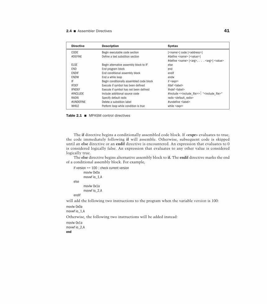
2.4.1 Control DirectivesThe control directives that are used most often are listed in Table 2.1. Directives that are
related are introduced in a group in the following:
if <expr>elseendif
2.4 � Assembler Directives 41
The if directive begins a conditionally assembled code block. If <expr> evaluates to true,the code immediately following if will assemble. Otherwise, subsequent code is skippeduntil an else directive or an endif directive is encountered. An expression that evaluates to 0is considered logically false. An expression that evaluates to any other value is consideredlogically true.
The else directive begins alternative assembly block to if. The endif directive marks the endof a conditional assembly block. For example,
if version == 100 ; check current versionmovlw 0x0amovwf io_1,A
elsemovlw 0x1amovwf io_2,A
endif
will add the following two instructions to the program when the variable version is 100:
movlw 0x0amovwf io_1,A
Otherwise, the following two instructions will be added instead:
movlw 0x1amovwf io_2,Aend
Directive Description Syntax
CODE Begin executable code section [<name>] code [<address>]#DEFINE Define a text substition section #define <name> [<value>]
#define <name> [<arg>, . . . <arg>] <value>ELSE Begin alternative assembly block to IF elseEND End program block endENDIF End conditional assembly block endifENDW End a while loop endwIF Begin conditionally assembled code block if <expr>IFDEF Execute if symbol has been defined ifdef <label>IFNDEF Execute if symbol has not been defined ifndef <label>#INCLUDE Include additional source code #include <<include_file>> “<include_file>”RADIX Specify default radix radix <default_radix>#UNDEFINE Delete a substition label #undefine <label>WHILE Perform loop while condition is true while <expr>
Table 2.1 � MPASM control directives
42 Chapter 2 � PIC18 Assembly Language Programming
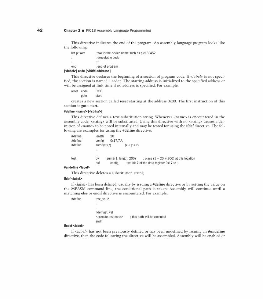
This directive indicates the end of the program. An assembly language program looks likethe following:
list p=xxxx ; xxxx is the device name such as pic18F452. ; executable code. ; “end ; end of program
[<label>] code [<ROM address>]
This directive declares the beginning of a section of program code. If <label> is not speci-fied, the section is named “.code”. The starting address is initialized to the specified address orwill be assigned at link time if no address is specified. For example,
reset code 0x00goto start
creates a new section called reset starting at the address 0x00. The first instruction of thissection is goto start.
#define <name> [<string>]
This directive defines a text substitution string. Whenever <name> is encountered in theassembly code, <string> will be substituted. Using this directive with no <string> causes a def-inition of <name> to be noted internally and may be tested for using the ifdef directive. The fol-lowing are examples for using the #define directive:
#define length 20#define config 0x17,7,A#define sum3(x,y,z) (x + y + z)
.
.test dw sum3(1, length, 200) ; place (1 + 20 + 200) at this location
bsf config ; set bit 7 of the data register 0x17 to 1#undefine <label>
This directive deletes a substitution string.
ifdef <label>
If <label> has been defined, usually by issuing a #define directive or by setting the value onthe MPASM command line, the conditional path is taken. Assembly will continue until amatching else or endif directive is encountered. For example,
#define test_val 2..ifdef test_val<execute test code> ; this path will be executedendif
ifndef <label>
If <label> has not been previously defined or has been undefined by issuing an #undefinedirective, then the code following the directive will be assembled. Assembly will be enabled or
2.4 � Assembler Directives 43
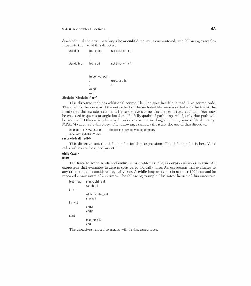
disabled until the next matching else or endif directive is encountered. The following examplesillustrate the use of this directive:
#define lcd_port 1 ; set time_cnt on..
#undefine lcd_port ; set time_cnt off..infdef led_port. ; execute this. ; “endifend
#include “<include_file>”
This directive includes additional source file. The specified file is read in as source code.The effect is the same as if the entire text of the included file were inserted into the file at thelocation of the include statement. Up to six levels of nesting are permitted. <include_ file> maybe enclosed in quotes or angle brackets. If a fully qualified path is specified, only that path willbe searched. Otherwise, the search order is current working directory, source file directory,MPASM executable directory. The following examples illustrate the use of this directive:
#include “p18F8720.inc” ;search the current working directory#include <p18F452.inc>
radix <default_radix>
This directive sets the default radix for data expressions. The default radix is hex. Validradix values are: hex, dee, or oct.
while <expr>endw
The lines between while and endw are assembled as long as <expr> evaluates to true. Anexpression that evaluates to zero is considered logically false. An expression that evaluates toany other value is considered logically true. A while loop can contain at most 100 lines and berepeated a maximum of 256 times. The following example illustrates the use of this directive:
test_mac macro chk_cntvariable i
i = 0while i < chk_cntmovlw i
i + = 1endwendm
starttest_mac 6end
The directives related to macro will be discussed later.
44 Chapter 2 � PIC18 Assembly Language Programming
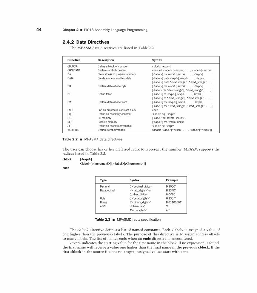
2.4.2 Data DirectivesThe MPASM data directives are listed in Table 2.2.
Directive Description Syntax
CBLOCK Define a block of constant cblock [<expr>]CONSTANT Declare symbol constant constant <label> [=<expr>, . . ., <label>[=<expr>]DA Store strings in program memory [<label>] da <expr>[,<expr>, . . ., <expr>]DATA Create numeric and text data [<label>] data <expr>[,<expr>, . . ., <expr>]
[<label>] data “<text string>”[, “<text_string>”, . . .]DB Declare data of one byte [<label>] db <expr>[,<expr>, . . ., <expr>]
[<label> db “<text string>”[, “<text_string>”, . . .]DT Define table [<label>] dt <expr>[,<expr>, . . ., <expr>]
[<label>] dt “<text_string>”[, “<text string>”, . . .]DW Declare data of one word [<label>] dw <expr>[,<expr>, . . ., <expr>]
[<label>] dw “<text_string>”[,”<text_string>”, . . .]ENDC End an automatic constant block endcEQU Define an assembly constant <label> equ <expr>FILL Fill memory [<label> fill <expr>,<count>RES Reserve memory [<label>] res <mem_units>SET Define an assembler variable <label> set <expr>VARIABLE Declare symbol variable variable <label>[=<expr>, . . ., <label>[=<expr>]]
Table 2.2 � MPASM* data directives
Type Syntax Example
Decimal D’<decimal digits>’ D’1000’Hexadecimal H’<hex_digits>’ or H’234D’
Ox<hex_digits> 0xC000Octal O’<oetal_digits>’ O’1357’Binary B’<binary_digits>’ B’01100001’ASCII ‘<character>’ ‘T’
A’<character>’ A’T’
Table 2.3 � MPASMD radix specification
The user can choose his or her preferred radix to represent the number. MPASM supports theradices listed in Table 2.3.
cblock [<expr>]<label>[:<increment>][,<label>[:<increment>]]
endc
The cblock directive defines a list of named constants. Each <label> is assigned a value ofone higher than the previous <label>. The purpose of this directive is to assign address offsetsto many labels. The list of names ends when an endc directive is encountered.
<expr> indicates the starting value for the first name in the block. If no expression is found,the first name will receive a value one higher than the final name in the previous cblock. If thefirst cblock in the source file has no <expr>, assigned values start with zero.
2.4 � Assembler Directives 45
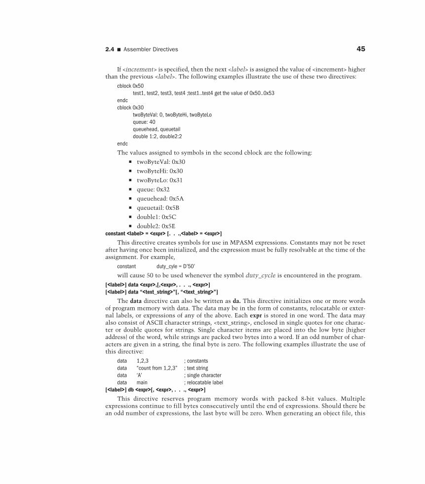
If <increment> is specified, then the next <label> is assigned the value of <increment> higherthan the previous <label>. The following examples illustrate the use of these two directives:
cblock 0x50test1, test2, test3, test4 ;test1..test4 get the value of 0x50..0x53
endccblock 0x30
twoByteVal: 0, twoByteHi, twoByteLoqueue: 40queuehead, queuetaildouble 1:2, double2:2
endc
The values assigned to symbols in the second cblock are the following:� twoByteVal: 0x30� twoByteHi: 0x30� twoByteLo: 0x31� queue: 0x32� queuehead: 0x5A� queuetail: 0x5B� double1: 0x5C� double2: 0x5E
constant <label> = <expr> [. . .,<label> = <expr>]
This directive creates symbols for use in MPASM expressions. Constants may not be resetafter having once been initialized, and the expression must be fully resolvable at the time of theassignment. For example,
constant duty_cyle = D’50’
will cause 50 to be used whenever the symbol duty_cycle is encountered in the program.
[<label>] data <expr>,[,<expr>, . . ., <expr>][<label>] data “<text_string>”[, “<text_string>”]
The data directive can also be written as da. This directive initializes one or more wordsof program memory with data. The data may be in the form of constants, relocatable or exter-nal labels, or expressions of any of the above. Each expr is stored in one word. The data mayalso consist of ASCII character strings, <text_string>, enclosed in single quotes for one charac-ter or double quotes for strings. Single character items are placed into the low byte (higheraddress) of the word, while strings are packed two bytes into a word. If an odd number of char-acters are given in a string, the final byte is zero. The following examples illustrate the use ofthis directive:
data 1,2,3 ; constantsdata “count from 1,2,3” ; text stringdata ‘A’ ; single characterdata main ; relocatable label
[<label>] db <expr>[, <expr>, . . ., <expr>]
This directive reserves program memory words with packed 8-bit values. Multipleexpressions continue to fill bytes consecutively until the end of expressions. Should there bean odd number of expressions, the last byte will be zero. When generating an object file, this
46 Chapter 2 � PIC18 Assembly Language Programming
directive can also be used to declare initialized data values. An example of the use of thisdirective is as follows:
db ‘b’,0x22, ‘t’, 0x1f, ‘s’, 0x03, ‘t’, ‘\n’[<label>] de <expr>[, <expr>, . . ., <expr>]
This directive reserves memory words with 8-bit data. Each <expr> must evaluate to an 8-bit value. The upper eight bits of the program word are zeroes. Each character in a string isstored in a separate word. Although designed for initializing EEPROM data on the PIC16C8X,the directive can be used at any location for any processor. An example of the use of this direc-tive is as follows:
org 0x2000de “this is my program”, 0 ; 0 is used to terminate the string
[<label>] dt <expr> [, <expr>, . . ., <expr>]
This directive generates a series of retlw instructions, one instruction for each <expr>. Each<expr> must be an 8-bit value. Each character in a string is stored in its own retlw instruction.The following examples illustrate the use of this directive:
dt “A new era is coming”, 0dt 1,2,3,4
[<label> dw <expr> [, <expr>, . . ., <expr>]
This directive reserves program memory words for data, initializing that space to specificvalues. Values are stored into successive memory locations, and the location is incremented byone. Expressions may be literal strings and are stored as described in the data directive.Examples on the use of this directive are as follows:
dw 39, 24, “display data”dw array_cnt–1
<label> equ <expr>
The equ directive defines a constant. Wherever the label appears in the program, the assem-bler will replace it with <expr>. Some examples of this directive are as follows:
true equ 1false equ 0four equ 4
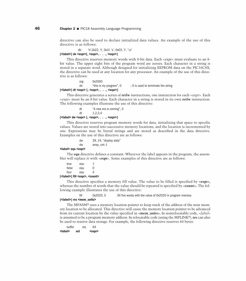
[<label>] fill <expr>, <count>
This directive specifies a memory fill value. The value to be filled is specified by <expr>,whereas the number of words that the value should be repeated is specified by <count>. The fol-lowing example illustrates the use of this directive:
fill 0x2020, 5 ;fill five words with the value of 0x2020 in program memory[<label>] res <mem_units>
The MPASM® uses a memory location pointer to keep track of the address of the next mem-ory location to be allocated. This directive will cause the memory location pointer to be advancedfrom its current location by the value specified in <mem_units>. In nonrelocatable code, <label>is assumed to be a program memory address. In relocatable code (using the MPLINK®), res can alsobe used to reserve data storage. For example, the following directive reserves 64 bytes:
buffer res 64<label> set <expr>
2.4 � Assembler Directives 47
Using this directive, <label> is assigned the value of the valid MPASM expression specifiedby <expr>. The set directive is functionally equivalent to the equ directive except that a setvalue may be subsequently altered by other set directive. The following examples illustrate theuse of this directive:
length set 0x20width set 0x21area_hi set 0x22area_lo set 0x23
variable <label> [=<expr>][,<label>[=<expr>] . . .]
This directive creates symbols for use in MPASM expressions. Variables and constants maybe used interchangeably in expressions. The variable directive creates a symbol that is func-tionally equivalent to those created by the set directive. The difference is that the variable direc-tive does not require that symbols be initialized when they are declared.
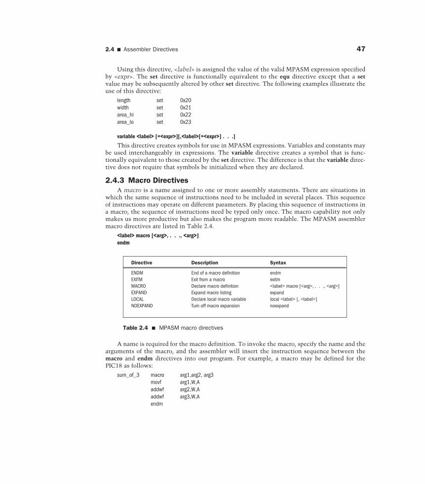
2.4.3 Macro DirectivesA macro is a name assigned to one or more assembly statements. There are situations in
which the same sequence of instructions need to be included in several places. This sequenceof instructions may operate on different parameters. By placing this sequence of instructions ina macro, the sequence of instructions need be typed only once. The macro capability not onlymakes us more productive but also makes the program more readable. The MPASM assemblermacro directives are listed in Table 2.4.
<label> macro [<arg>, . . ., <arg>]endm
Directive Description Syntax
ENDM End of a macro definition endmEXITM Exit from a macro exitmMACRO Declare macro definition <label> macro [<arg>, . . ., <arg>]EXPAND Expand macro listing expandLOCAL Declare local macro variable local <label> [, <label>]NOEXPAND Turn off macro expansion noexpand
Table 2.4 � MPASM macro directives
A name is required for the macro definition. To invoke the macro, specify the name and thearguments of the macro, and the assembler will insert the instruction sequence between themacro and endm directives into our program. For example, a macro may be defined for thePIC18 as follows:
sum_of_3 macro arg1,arg2, arg3movf arg1,W,Aaddwf arg2,W,Aaddwf arg3,W,Aendm
48 Chapter 2 � PIC18 Assembly Language Programming
If the user wants to add three data registers at 0x20, 0x21, and 0x22 and leave the sum inWREG, he or she can use the following statement to invoke the previously mentioned macro:
sum_of_3 0x20,0x21,0x22
When processing this macro call, the assembler will insert the following instructions in theuser program:
movf 0x20,W,Aaddwf 0x21,W,Aaddwf 0x22,W,A
exitm
This directive forces immediate return from macro expansion during assembly. The effectis the same as if an endm directive had been encountered. An example of the use of this direc-tive is as follows:
test macro arg1if arg1 == 3 ; check for valid file register
exitmelse
error “bad file assignment”endifendm
expandnoexpand
The expand directive tells the assembler to expand all macros in the listing file, whereasthe noexpand directive tells the assembler to do the opposite.
local <label>[,<label> . . .]
This directive declares that the specified data elements are to be considered in local con-text to the macro. <label> may be identical to another label declared outside the macro defini-tion; there will be no conflict between the two. The following example illustrates the use of thisdirective:
<main code segment>..
len equ 5 ; global versionwidth equ 8 ;abc macro width
local len, label ; local len and labellen set width ; modify local lenlabel res len ; reserve bufferlen set len-10
endm ; end macro
2.4.4 Listing DirectivesListing directives are used to control the MPASM listing file format. The listing directives
are listed in Table 2.5.
2.4 � Assembler Directives 49
error “<text_string>”
This directive causes <text_string> to be printed in a format identical to any MPASM errormessage. The error message will be output in the assembler list file. <text_string> may be from1 to 80 characters. The following example illustrates the use of this directive:
bnd_check macro arg1if arg1 >= 0x20
error “argument out of range”endifendm
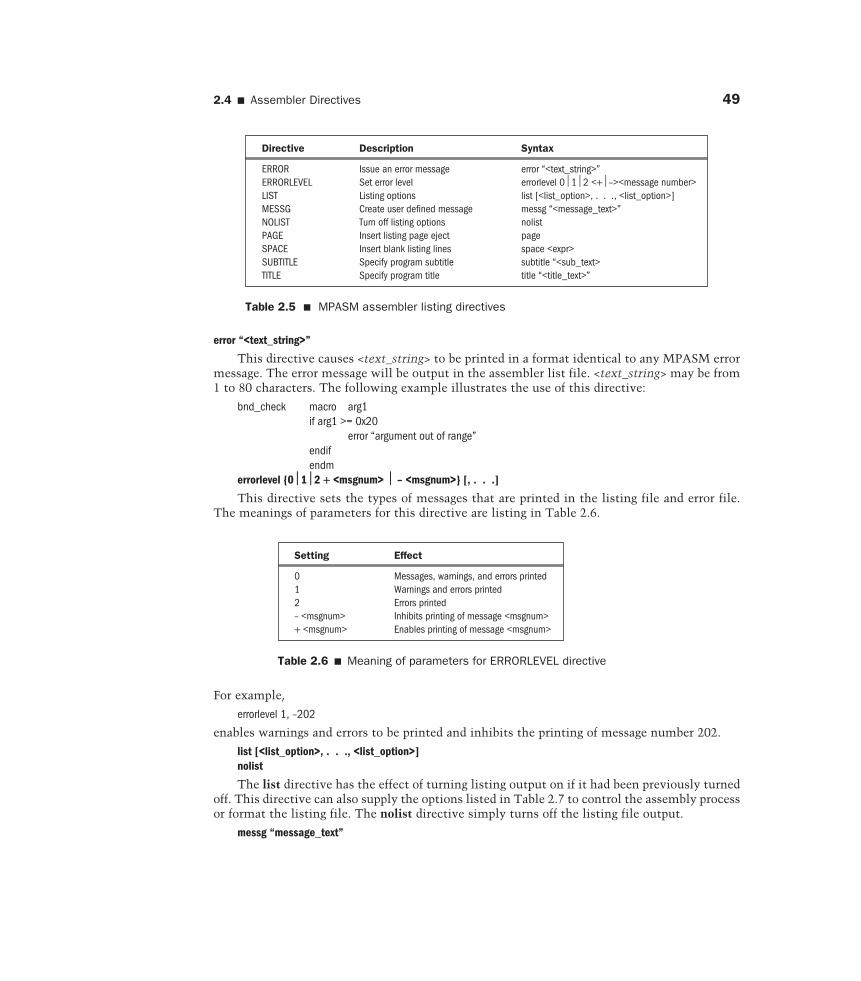
errorlevel {0ö1ö2 + <msgnum> ö – <msgnum>} [, . . .]
This directive sets the types of messages that are printed in the listing file and error file.The meanings of parameters for this directive are listing in Table 2.6.
Directive Description Syntax
ERROR Issue an error message error “<text_string>”ERRORLEVEL Set error level errorlevel 012 <+–><message number>LIST Listing options list [<list_option>, . . ., <list_option>]MESSG Create user defined message messg “<message_text>”NOLIST Turn off listing options nolistPAGE Insert listing page eject pageSPACE Insert blank listing lines space <expr>SUBTITLE Specify program subtitle subtitle “<sub_text>TITLE Specify program title title “<title_text>”
Setting Effect
0 Messages, warnings, and errors printed1 Warnings and errors printed2 Errors printed– <msgnum> Inhibits printing of message <msgnum>+ <msgnum> Enables printing of message <msgnum>
Table 2.5 � MPASM assembler listing directives
Table 2.6 � Meaning of parameters for ERRORLEVEL directive
For example,
errorlevel 1, –202
enables warnings and errors to be printed and inhibits the printing of message number 202.
list [<list_option>, . . ., <list_option>]nolist
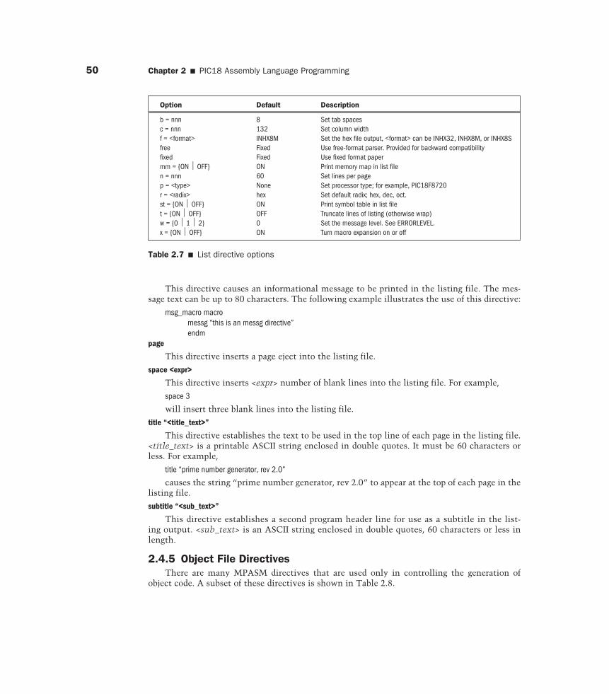
The list directive has the effect of turning listing output on if it had been previously turnedoff. This directive can also supply the options listed in Table 2.7 to control the assembly processor format the listing file. The nolist directive simply turns off the listing file output.
messg “message_text”
50 Chapter 2 � PIC18 Assembly Language Programming
This directive causes an informational message to be printed in the listing file. The mes-sage text can be up to 80 characters. The following example illustrates the use of this directive:
msg_macro macromessg “this is an messg directive”endm
page
This directive inserts a page eject into the listing file.
space <expr>
This directive inserts <expr> number of blank lines into the listing file. For example,
space 3
will insert three blank lines into the listing file.
title “<title_text>”
This directive establishes the text to be used in the top line of each page in the listing file.<title_text> is a printable ASCII string enclosed in double quotes. It must be 60 characters orless. For example,
title “prime number generator, rev 2.0”
causes the string “prime number generator, rev 2.0” to appear at the top of each page in thelisting file.
subtitle “<sub_text>”
This directive establishes a second program header line for use as a subtitle in the list-ing output. <sub_text> is an ASCII string enclosed in double quotes, 60 characters or less inlength.
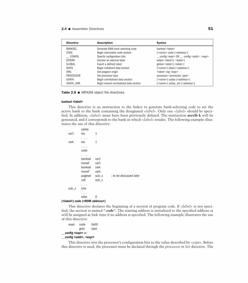
2.4.5 Object File DirectivesThere are many MPASM directives that are used only in controlling the generation of
object code. A subset of these directives is shown in Table 2.8.
Option Default Description
b = nnn 8 Set tab spacesc = nnn 132 Set column widthf = <format> INHX8M Set the hex file output, <format> can be INHX32, INHX8M, or INHX8Sfree Fixed Use free-format parser. Provided for backward compatibilityfixed Fixed Use fixed format papermm = {ON OFF} ON Print memory map in list filen = nnn 60 Set lines per pagep = <type> None Set processor type; for example, PIC18F8720r = <radix> hex Set default radix; hex, dec, oct.st = {ON OFF} ON Print symbol table in list filet = {ON OFF} OFF Truncate lines of listing (otherwise wrap)w = {0 1 2} 0 Set the message level. See ERRORLEVEL.x = {ON OFF} ON Turn macro expansion on or off
Table 2.7 � List directive options
2.4 � Assembler Directives 51
banksel <label>
This directive is an instruction to the linker to generate bank-selecting code to set theactive bank to the bank containing the designated <label>. Only one <label> should be speci-fied. In addition, <label> must have been previously defined. The instruction movlb k will begenerated, and k corresponds to the bank in which <label> resides. The following example illus-trates the use of this directive:
udatavar1 res 1
. . .vark res 1
. . .code. . .banksel var1movwf var1banksel varkmovwf varkpagesel sub_x ; to be discussed latercall sub_x. . .
sub_x clrw. . .retlw 0
[<label>] code [<ROM address>]
This directive declares the beginning of a section of program code. If <label> is not speci-fied, the section is named “.code”. The starting address is initialized to the specified address orwill be assigned at link time if no address is specified. The following example illustrates the useof this directive:
reset code 0x00goto start
__config <expr> or__config <addr>, <expr>
This directive sets the processor’s configuration bits to the value described by <expr>. Beforethis directive is used, the processor must be declared through the processor or list directive. The
Directive Description Syntax
BANKSEL Generate RAM bank selecting code banksel <label>CODE Begin executable code section [<name> code [<address>]__ CONFIG Specify configuration bits __config <expr> OR __ config <addr>, <expr>EXTERN Declare an external label extern <label>[, <label>]GLOBAL Export a defined label global <label>[,<label>]IDATA Begin initialized data section [<name>] idata [<address>]ORG Set program origin <label> org <expr>PROCESSOR Set processor type processor <processor_type>UDATA Begin uninitialized data section [<name>] udata [<address>]UDATA_SHR Begin shared uninitialized data section [<name>] udata_shr [<address>]
Table 2.8 � MPASM object file directives
52 Chapter 2 � PIC18 Assembly Language Programming
hex file output format must be set to INHX32 with the list directive when this directive is usedwith the PIC18 family. The following example illustrates the use of this directive:
list p = 18F8720, f = INHX32__config 0xFFFF ; default configuration bits
extern <label> [, <label>, . . .]
This directive declares symbols names that may be used in the current module but aredefined as global in a different module. The external statement must be included before <label>is used. At least one label must be specified on the line. The following example illustrates theuse of this directive:
extern function_x. . .
call function_x
global <label> [, <label>, . . .]
This directive declares symbol names that are defined in the current module and should beavailable to other modules. This directive must be used after <label> is defined. At least one labelmust be included in this directive. The following example illustrates the use of this directive:
udataax res 1bx res 1
global ax, bxcodeaddlw 3. . .
[<label> idata [<RAM address>]
This directive declares the beginning of a section of initialized data. If <label> is not spec-ified, the section is named “.data”. The starting address is initialized to the specified address orwill be assigned at link time if no address is specified. No code can be generated in this section.The res, db, and dw directives may be used to reserve space for variables. The res directive willgenerate an initial value of zero. The db directive will initialize successive bytes of RAM. Thedw directive will initialize successive bytes of RAM, one word at a time, in low-byte/high-byteorder. The following example illustrates the use of this directive:
idatai dw 0j dw 0t_cnt dw 20flags db 0prompt db “hello there!”
[<label>] org <expr>
This directive sets the program origin for subsequent code at the address defined in <expr>.If <label> is specified, it will be given the value of the <expr>. If no org is specified, code gener-ation will begin at address zero. Some examples of this directive follow:
reset org 0x00. . . ; reset vector code goes havegoto startorg 0x100
start . . . ; code of our program

2.5 � Representing the Program Logic 53
processor <processor_type>
This directive sets the processor type. For example,
processor p18F8720
[<label>] udata [<RAM address>]
This directive declares the beginning of a section of uninitialized data. If <label> is notspecified, the section is named “.udata”. The starting address is initialized to the specifiedaddress or will be assigned at link time if no address is specified. No code can be generated inthis section. The res directive should be used to reserve space or data. Here is an example thatillustrates the use of this directive:
udatavar1 res 1var2 res 2
[<label>] udata_shr [<RAM address>]
This directive declares the beginning of a section of shared uninitialized data. If <label> is notspecified, the section is named “.udata_shr”. The starting address is initialized to the specifiedaddress or will be assigned at link time if no address is specified. This directive is used to declarevariables that are allocated in RAM and are shared across all RAM banks. The res directive shouldbe used to reserve space for data. The following examples illustrate the use of this directive:
temps udata_shrt1 res 1t2 res 1s1 res 2s2 res 4
2.5 Representing the Program Logic
An embedded product designer must spend a significant amount of time on software develop-ment. It is important for the embedded product designer to understand software development issues.
Software development starts with the problem definition. The problem presented by theapplication must be fully understood before any program can be written. At the problem defi-nition stage, the most critical thing is to get you, the programmer, and your end user to agreeon what needs to be done. To achieve this, asking questions is very important. For complex andexpensive applications, a formal, written definition of the problem is formulated and agreed onby all parties.
Once the problem is known, the programmer can begin to lay out an overall plan of how tosolve the problem. The plan is also called an algorithm. Informally, an algorithm is any well-defined computational procedure that takes some value or a set of values as input and producessome value or set of values as output. An algorithm is thus a sequence of computational stepsthat transform input to output. An algorithm can also be viewed as a tool for solving a well-specified computational problem. The statement of the problem specifies in general terms thedesired input/output relationship. The algorithm describes a specific computational procedurefor achieving that input/output relationship.
An algorithm is expressed in pseudocode that is very much like C or Pascal. Pseudocode isdistinguished from “real” code in that pseudocode employs whatever expressive method is mostclear and concise to specify a given algorithm. Sometimes, the clearest method is English, so donot be surprised if you come across an English phrase or sentence embedded within a section of“real” code.
54 Chapter 2 � PIC18 Assembly Language Programming
An algorithm provides not only the overall plan for solving the problem but also documen-tation to the software to be developed. In the rest of this book, all algorithms will be presentedin the format as follows:
Step 1. . .
Step 2. . .An earlier alternative for providing the overall plan for solving software problem is using
flowcharts. A flowchart shows the way a program operates. It illustrates the logic flow of theprogram. Therefore, flowcharts can be a valuable aid in visualizing programs. Many people pre-fer using flowcharts in representing the program logic for this reason. Flowcharts are used notonly in computer programming but in many other fields as well, such as business and con-struction planning.
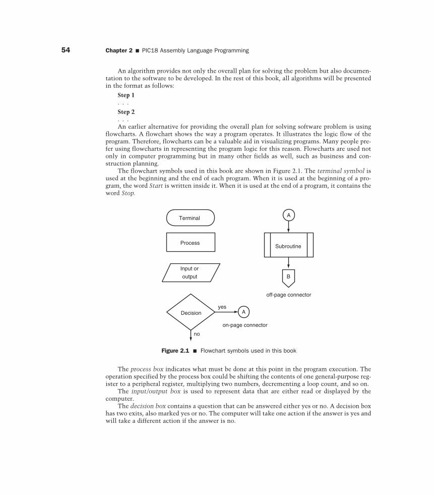
The flowchart symbols used in this book are shown in Figure 2.1. The terminal symbol isused at the beginning and the end of each program. When it is used at the beginning of a pro-gram, the word Start is written inside it. When it is used at the end of a program, it contains theword Stop.
Terminal
Process
Input or
output
Decisionyes
no
Subroutine
B
A
A
on-page connector
off-page connector
Figure 2.1 � Flowchart symbols used in this book
The process box indicates what must be done at this point in the program execution. Theoperation specified by the process box could be shifting the contents of one general-purpose reg-ister to a peripheral register, multiplying two numbers, decrementing a loop count, and so on.
The input/output box is used to represent data that are either read or displayed by the computer.
The decision box contains a question that can be answered either yes or no. A decision boxhas two exits, also marked yes or no. The computer will take one action if the answer is yes andwill take a different action if the answer is no.
2.6 � A Template for Writing Assembly Programs 55
The on-page connector indicates that the flowchart continues elsewhere on the same page.The place where it is continued will have the same label as the on-page connector. The off-pageconnector indicates that the flowchart continues on another page. To determine where theflowchart continues, one needs to look at the following pages of the flowchart to find the match-ing off-page connector.
Normal flow on a flowchart is from top to bottom and from left to right. Any line that doesnot follow this normal flow should have an arrowhead on it.
When the program gets complicated, the flowchart that documents the logic flow of theprogram also becomes difficult to follow. This is the limitation of the flowchart. In this book,both the flowchart and the algorithm procedure are mixed to describe the solution to a problem.
After one is satisfied with the algorithm or the flowchart, one can convert it to source codein one of the assembly or high-level languages. Each statement in the algorithm (or each blockin the flowchart) will be converted into one or multiple assembly instructions or high-level lan-guage statements. If an algorithmic step (or a block in the flowchart) requires many assemblyinstructions or high-level language statements to implement, then it might be beneficial toeither (1) convert this step (or block) into a subroutine and just call the subroutine or (2) furtherdivide the algorithmic step (or flowchart block) into smaller steps (or blocks) so that it can becoded with just a few assembly instructions or high-level language statements.
The next major step is program testing, which means testing for anomalies. Here one willfirst test for normal inputs that one always expects. If the result is as one expects, then onegoes on to test the borderline inputs. Test for the maximum and minimum values of theinput. When the program passes this test also, one continues to test for illegal input values.If the algorithm includes several branches, then enough values should be used to exercise allthe possible branches to make sure that the program will operate correctly under all possiblecircumstances.
In the rest of this book, most of the examples are well defined. Therefore, our focus is onhow to design the algorithm that solves the specified problem and also convert the algorithminto source code.
2.6 A Template for Writing Assembly Programs
When testing a user program, it should be considered as the only program executed by thecomputer. To achieve that, it should be written in a way that can be executed immediately outof reset. The following format will allow us to do that:
org 0x0000goto startorg 0x08. . . ;high-priority interrupt service routineorg 0x18. . . ;low-priority interrupt service routine
start . . .. . . ;your programend
The PIC18 MCU reserves a small block of memory locations to hold the reset handling rou-tine and high-priority and low-priority interrupt service routines. The reset, the high-priorityinterrupt, and the low-priority interrupt service routines start at 0x000, 0x0008, and 0x0018,respectively. The user program should start somewhere after 0x0018.
56 Chapter 2 � PIC18 Assembly Language Programming
In an application, the reset handling routine will be responsible for initializing the MCUhardware and performing any necessary housekeeping functions. The reset signal will providedefault values to many key registers and allow the MCU to operate. At this moment, the userwill take advantage of this by simply using the goto instruction to jump to the starting point ofthe user program. By doing this, the user program can be tested.
Since interrupt handling has not been covered yet, we will be satisfied by making both thehigh- and the low-priority interrupt service routines dummy routines that do nothing but simplyreturn. This can be achieved by placing the retfie instruction in the default location. Therefore,the following template will be used to test the user program until interrupts are discussed:
org 0x0000goto start ;reset handling routineorg 0x08retfie ;high-priority interrupt service routineorg 0x18retfie ;low-priority interrupt service routine
start . . .. . . ;your programend
2.7 Case Issue
The PIC18 instructions can be written in uppercase or lowercase. However, MicrochipMPASM cross assembler is case sensitive. Microchip provides a free integrated development envi-ronment MPLAB IDE to all of its users. The MPLAB IDE provides an include file for every MCUmade by Microchip. Each of these include files provides the definitions of all special-function reg-isters for the specific MCU. All function registers and their individual bits are defined in upper-case. Since one will include one of these MCU include files in his or her assembly program, usinguppercase for special-function register names becomes necessary. The convention adopted in thisbook is to use lowercase for instruction and directive mnemonics but uppercase for all functionregisters and their bits.
2.8 Writing Programs to Perform Arithmetic Computations
The PIC18 MCU has instructions for performing 8-bit addition, subtraction, and multipli-cation operations. Operations that deal with operands longer than eight bits can be synthesizedby using a sequence of appropriate instructions. The PIC18 MCU provides no instruction fordivision, and hence this operation must also be synthesized by an appropriate sequence ofinstructions. The algorithm for implementing division operation will be discussed in Chapter 4.
In this section, smaller programs that perform simple computations will be used to demon-strate how a program is written.
2.8.1 Perform Addition OperationsAs discussed in Chapter 1, the PIC18 MCU has two ADD instructions with two operands
and one ADD instruction with three operands. These ADD instructions are designed to per-form 8-bit additions. The execution result of the ADD instruction will affect all flag bits of theSTATUS register.
2.8 � Writing Programs to Perform Arithmetic Computations 57
The three-operand ADD instruction will be needed in performing multibyte ADD opera-tions. For an 8-bit MCU, a multibyte addition is also called a multiprecision addition. A multi-precision addition must be performed from the least significant byte toward the mostsignificant byte, just like numbers are added from the least significant digit toward the mostsignificant digit.
When dealing with multibyte numbers, there is an issue regarding how the number isstored in memory. If the least significant byte of the number is stored at the lowest address,then the byte order is called little-endian. Otherwise, the byte order is called big-endian. Thistext will follow the little-endian byte order in order to be compatible with the MPLAB IDE soft-ware from Microchip. MPLAB IDE will be used throughout this text.
Example 2.4�
Write a program that adds the three numbers stored in data registers at 0x20, 0x30, and0x40 and places the sum in data register at 0x50.
Solution: The algorithm for adding three numbers is as follows:
Step 1Load the number stored at 0x20 into the WREG register.
Step 2Add the number stored at 0x30 and the number in the WREG register and leave the sum inthe WREG register.
Step 3Add the number stored at 0x40 and the number in the WREG register and leave the sum inthe WREG register.
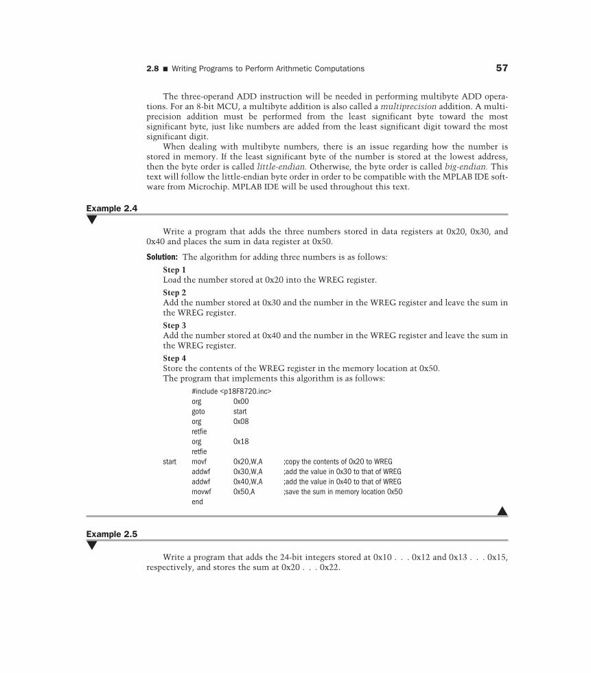
Step 4Store the contents of the WREG register in the memory location at 0x50.The program that implements this algorithm is as follows:
#include <p18F8720.inc>org 0x00goto startorg 0x08retfieorg 0x18retfie
start movf 0x20,W,A ;copy the contents of 0x20 to WREGaddwf 0x30,W,A ;add the value in 0x30 to that of WREGaddwf 0x40,W,A ;add the value in 0x40 to that of WREGmovwf 0x50,A ;save the sum in memory location 0x50end
�
Example 2.5�
Write a program that adds the 24-bit integers stored at 0x10 . . . 0x12 and 0x13 . . . 0x15,respectively, and stores the sum at 0x20 . . . 0x22.
58 Chapter 2 � PIC18 Assembly Language Programming
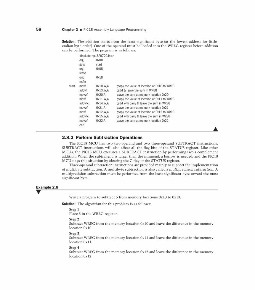
Solution: The addition starts from the least significant byte (at the lowest address for little-endian byte order). One of the operand must be loaded into the WREG register before additioncan be performed. The program is as follows:
#include <p18F8720.inc>org 0x00goto startorg 0x08retfieorg 0x18retfie
start movf 0x10,W,A ;copy the value of location at 0x10 to WREGaddwf 0x13,W,A ;add & leave the sum in WREGmovwf 0x20,A ;save the sum at memory location 0x20movf 0x11,W,A ;copy the value of location at 0x11 to WREGaddwfc 0x14,W,A ;add with carry & leave the sum in WREGmovwf 0x21,A ;save the sum at memory location 0x21movf 0x12,W,A ;copy the value of location at 0x12 to WREGaddwfc 0x15,W,A ;add with carry & leave the sum in WREGmovwf 0x22,A ;save the sum at memory location 0x22end
�
2.8.2 Perform Subtraction OperationsThe PIC18 MCU has two two-operand and two three-operand SUBTRACT instructions.
SUBTRACT instructions will also affect all the flag bits of the STATUS register. Like otherMCUs, the PIC18 MCU executes a SUBTRACT instruction by performing two’s complementaddition. When the subtrahend is larger than the minuend, a borrow is needed, and the PIC18MCU flags this situation by clearing the C flag of the STATUS register.
Three-operand subtraction instructions are provided mainly to support the implementationof multibyte subtraction. A multibyte subtraction is also called a multiprecision subtraction. Amultiprecision subtraction must be performed from the least significant byte toward the mostsignificant byte.
Example 2.6�
Write a program to subtract 5 from memory locations 0x10 to 0x13.
Solution: The algorithm for this problem is as follows:
Step 1Place 5 in the WREG register.
Step 2Subtract WREG from the memory location 0x10 and leave the difference in the memorylocation 0x10.
Step 3Subtract WREG from the memory location 0x11 and leave the difference in the memorylocation 0x11.
Step 4Subtract WREG from the memory location 0x12 and leave the difference in the memorylocation 0x12.
Step 5Subtract WREG from the memory location 0x13 and leave the difference in the memorylocation 0x13.
The assembly program that implements this algorithm is as follows:
#include <p18F8720.inc>org 0x00goto startorg 0x08retfieorg 0x18retfie
start movlw 0x05 ;place the value 5 in WREGsubwf 0x10,F,A ;subtract 5 from memory location 0x10subwf 0x11,F,A ;subtract 5 from memory location 0x11subwf 0x12,F,A ;subtract 5 from memory location 0x12subwf 0x13,F,A ;subtract 5 from memory location 0x13end
�
Example 2.7�
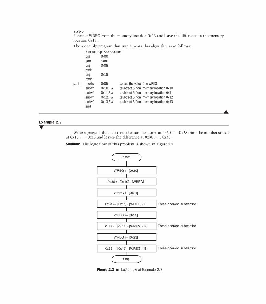
Write a program that subtracts the number stored at 0x20 . . . 0x23 from the number storedat 0x10 . . . 0x13 and leaves the difference at 0x30 . . . 0x33.
Solution: The logic flow of this problem is shown in Figure 2.2.
Start
WREG ← [0x20]
0x30 ← [0x10] - [WREG]
WREG ← [0x21]
0x31 ← [0x11] - [WREG] - B
WREG ← [0x22]
0x32 ← [0x12] - [WREG] - B
WREG ← [0x23]
0x33 ← [0x13] - [WREG] - B
Stop
Three-operand subtraction
Three-operand subtraction
Three-operand subtraction
Figure 2.2 � Logic flow of Example 2.7
60 Chapter 2 � PIC18 Assembly Language Programming
The program that implements the logic illustrated in Figure 2.2 is as follows:
#include <p18F8720.inc>org 0x00goto startorg 0x08retfieorg 0x18retfie
start movf 0x20, W, Asubwf 0x10, W, A ;subtract the least significant bytemovwf 0x30, Amovf 0x21, W, Asubwfb 0x11, W, A ;subtract the second to least significant bytemovwf 0x31, Amovf 0x22, W, Asubwfb 0x12, W, A ;subtract the second to most significant bytemovwf 0x32, Amovf 0x23, W, Asubwfb 0x13, W, A ;subtract the most significant bytemovwf 0x33, Aend
�
2.8.3 Binary Coded Decimal AdditionAll computers perform arithmetic using binary arithmetic. However, input and output
equipment generally uses decimal numbers because we are used to decimal numbers. Computerscan work on decimal numbers as long as they are encoded properly. The most common way toencode decimal numbers is to use four bits to encode each decimal digit. For example, 1234 isencoded as 0001 0010 0011 0100. This representation is called binary-coded decimal (BCD). IfBCD format is used, it must be preserved during the arithmetic processing.
The BCD representation simplifies input/output conversion but complicates the internalcomputation. The use of the BCD representation must be carefully justified.
The PIC18 MCU performs all arithmetic in binary format. The following instructionsequence appears to cause the PIC18 MCU to add the decimal numbers 31 and 47 and store thesum at the memory location 0x50:
movlw 0x31addlw 0x47movwf 0x50, A
This instruction sequence performs the following addition:
h 3 1+ h 4 7
h 7 8
2.8 � Writing Programs to Perform Arithmetic Computations 61
When the PIC18 MCU executes this instruction sequence, it adds the numbers according to therules of binary addition and produces the sum h’78’, which is a correct decimal number. However,a problem occurs when the PIC18 MCU adds two BCD digits that yield a sum larger than 9:
h 2 4 h 3 6 h 2 9+ h 6 7 + h 4 7 + h 4 7
h 8 B h 7 D h 7 0
The first two additions are obviously incorrect because the results have illegal characters. Thethird example does not contain any illegal character. However, the correct result should be 76instead of 70. There is a carry from the lower digit to the upper digit.
In summary, a sum in BCD is incorrect if the sum is greater than 9 or if there is a carry fromthe lower digit to the upper digit. Incorrect BCD sums can be adjusted by performing the fol-lowing operations:
1. Add 0x6 to every sum digit greater than 9.
2. Add 0x6 to every sum digit that had a carry of 1 to the next higher digit.
These problems are corrected as follows:
h 2 4 h 3 6 h 2 9+ h 6 7 + h 4 7 + h 4 7
h 8 B h 7 D h 7 0+ h 6 + h 6 + h 6
h 9 1 h 8 3 h 7 6
The bit 1 of the STATUS register is the digit carry (DC) flag that indicates if there is a carry frombit 3 to bit 4 of the addition result. The decimal adjust WREG (daw) instruction adjust the 8-bitvalue in the WREG register resulting from the earlier addition of two variables (each in packedBCD format) and produces a correctly packed BCD result. Multibyte decimal addition is alsopossible by using the DAW instruction.
Example 2.8�
Write an instruction sequence that adds the decimal number stored in 0x23 and 0x24together and stores the sum in 0x25. The result must also be in BCD format.
Solution: The instruction is as follows:
movf 0x23,W,Aaddwf 0x24,W,Adawmovwf 0x25,A
�
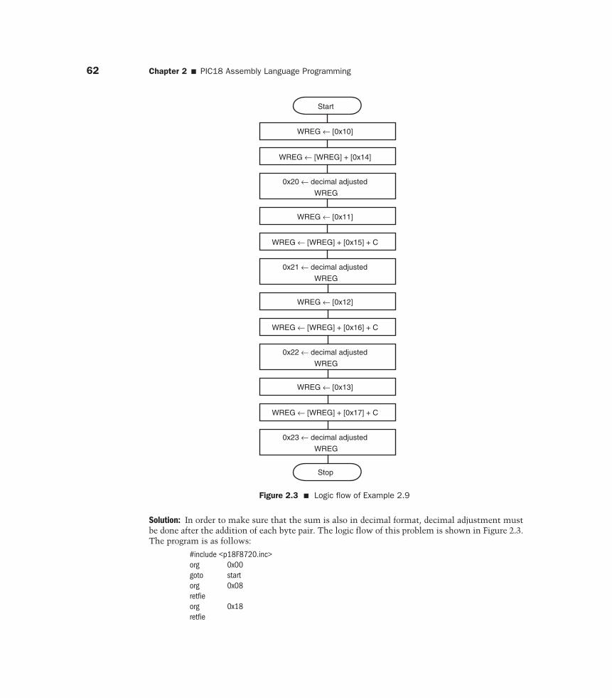
Example 2.9�
Write an instruction sequence that adds the decimal numbers stored at 0x10 . . . 0x13 and0x14 . . . 0x17 and stores the sum in ox20 . . . 0x23. All operands are in the access bank.
62 Chapter 2 � PIC18 Assembly Language Programming
Start
WREG ← [0x10]
Stop
WREG ← [WREG] + [0x14]
0x20 ← decimal adjusted
WREG
WREG ← [0x11]
WREG ← [WREG] + [0x15] + C
0x21 ← decimal adjusted
WREG
WREG ← [0x12]
WREG ← [WREG] + [0x16] + C
0x22 ← decimal adjusted
WREG
WREG ← [0x13]
WREG ← [WREG] + [0x17] + C
0x23 ← decimal adjusted
WREG
Figure 2.3 � Logic flow of Example 2.9
Solution: In order to make sure that the sum is also in decimal format, decimal adjustment mustbe done after the addition of each byte pair. The logic flow of this problem is shown in Figure 2.3.The program is as follows:
#include <p18F8720.inc>org 0x00goto startorg 0x08retfieorg 0x18retfie
2.8 � Writing Programs to Perform Arithmetic Computations 63
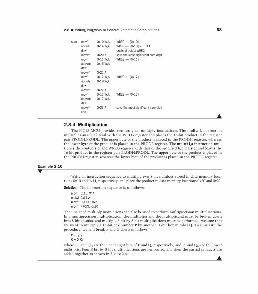
start movf 0x10,W,A ;WREG ← [0x10]addwf 0x14,W,A ;WREG ← [0x10] + [0x14]daw ;decimal adjust WREGmovwf 0x20,A ;save the least significant sum digitmovf 0x11,W,A ;WREG ← [0x11]addwfc 0x15,W,Adawmovwf 0x21,Amovf 0x12,W,A ;WREG ← [0x12]addwfc 0x16,W,Adawmovwf 0x22,Amovf 0x13,W,A ;WREG ← [0x13]addwfc 0x17,W,Adawmovwf 0x23,A ;save the most significant sum digitend
�
2.8.4 MultiplicationThe PIC18 MCU provides two unsigned multiply instructions. The mullw k instruction
multiplies an 8-bit literal with the WREG register and places the 16-bit product in the registerpair PRODH:PRODL. The upper byte of the product is placed in the PRODH register, whereasthe lower byte of the product is placed in the PRODL register. The mulwf f,a instruction mul-tiplies the contents of the WREG register with that of the specified file register and leaves the16-bit product in the register pair PRODH:PRODL. The upper byte of the product is placed inthe PRODH register, whereas the lower byte of the product is placed in the PRODL register.
Example 2.10�
Write an instruction sequence to multiply two 8-bit numbers stored in data memory loca-tions 0x10 and 0x11, respectively, and place the product in data memory locations 0x20 and 0x21.
Solution: The instruction sequence is as follows:
movf 0x10, W,Amulwf 0x11,Amovff PRODH, 0x21movff PRODL, 0x20
The unsigned multiply instructions can also be used to perform multiprecision multiplications.In a multiprecision multiplication, the multiplier and the multiplicand must be broken downinto 8-bit chunks, and multiple 8-bit by 8-bit multiplications must be performed. Assume thatwe want to multiply a 16-bit hex number P by another 16-bit hex number Q. To illustrate theprocedure, we will break P and Q down as follows:
P = PHPL
Q = QHQL
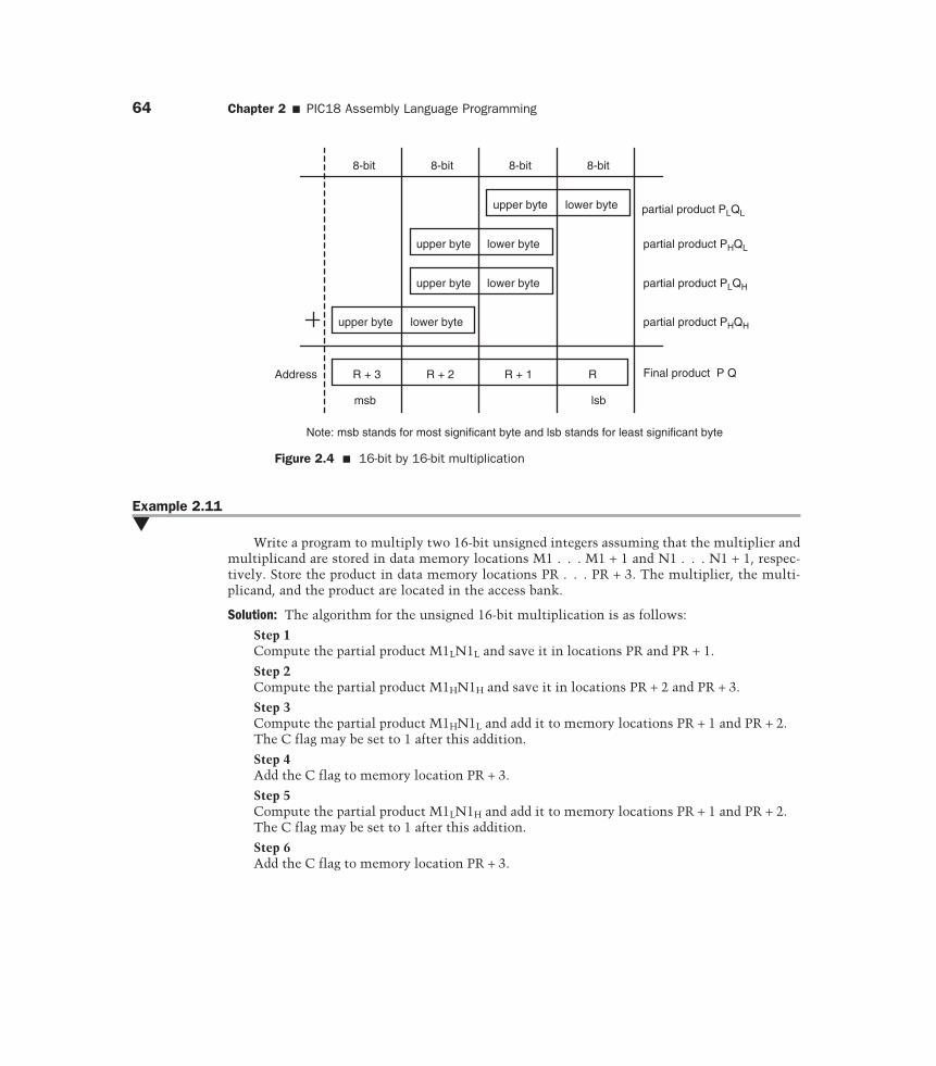
where PH and QH are the upper eight bits of P and Q, respectively, and PL and QL are the lowereight bits. Four 8-bit by 8-bit multiplications are performed, and then the partial products areadded together as shown in Figure 2.4.
�
64 Chapter 2 � PIC18 Assembly Language Programming
Example 2.11�
Write a program to multiply two 16-bit unsigned integers assuming that the multiplier andmultiplicand are stored in data memory locations M1 . . . M1 + 1 and N1 . . . N1 + 1, respec-tively. Store the product in data memory locations PR . . . PR + 3. The multiplier, the multi-plicand, and the product are located in the access bank.
Solution: The algorithm for the unsigned 16-bit multiplication is as follows:
Step 1Compute the partial product M1LN1L and save it in locations PR and PR + 1.
Step 2Compute the partial product M1HN1H and save it in locations PR + 2 and PR + 3.
Step 3Compute the partial product M1HN1L and add it to memory locations PR + 1 and PR + 2.The C flag may be set to 1 after this addition.
Step 4Add the C flag to memory location PR + 3.
Step 5Compute the partial product M1LN1H and add it to memory locations PR + 1 and PR + 2.The C flag may be set to 1 after this addition.
Step 6Add the C flag to memory location PR + 3.
8-bit 8-bit 8-bit 8-bit
R + 3 R + 2 R + 1 R
upper byte
upper byte
upper byte
upper byte lower byte
lower byte
lower byte
lower byte
Address
partial product PLQL
partial product PHQL
partial product PLQH
partial product PHQH
Final product P Q
msb lsb
Note: msb stands for most significant byte and lsb stands for least significant byte
Figure 2.4 � 16-bit by 16-bit multiplication
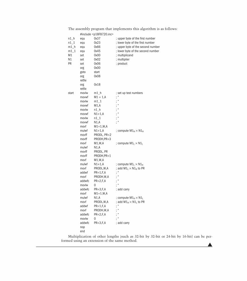
The assembly program that implements this algorithm is as follows:
#include <p18F8720.inc>n1_h equ 0x37 ; upper byte of the first numbern1_1 equ 0x23 ; lower byte of the first numberm1_h equ 0x66 ; upper byte of the second numberm1_1 equ 0x45 ; lower byte of the second numberM1 set 0x00 ; multiplicandN1 set 0x02 ; multiplierPR set 0x06 ; product
org 0x00goto startorg 0x08retfieorg 0x18retfie
start movlw m1_h ; set up test numbersmovwf M1 + 1,A ; “movlw m1_1 ; “movwf M1,A ; “movlw n1_h ; “movwf N1+1,A ; “movlw n1_1 ; “movwf N1,A ; “movf M1+1,W,Amulwf N1+1,A ; compute M1H × N1H
movff PRODL, PR+2movff PRODH,PR+3movf M1,W,A ; compute M1L × N1L
mulwf N1,Amovff PRODL, PRmovff PRODH,PR+1movf M1,W,Amulwf N1+1,A ; compute M1L × N1H
movf PRODL,W,A ; add M1L × N1H to PRaddwf PR+1,F,A ; “movf PRODH,W,A ; “addwfc PR+2,F,A ; “movlw 0 ; “addwfc PR+3,F,A ; add carrymovf M1+1,W,Amulwf N1,A ; compute M1H × N1L
movf PRODL,W,A ; add M1H × N1L to PRaddwf PR+1,F,A ; “movf PRODH,W,A ; “addwfc PR+2,F,A ; “movlw 0 ; “addwfc PR+3,F,A ; add carrynopend
Multiplication of other lengths (such as 32-bit by 32-bit or 24-bit by 16-bit) can be per-formed using an extension of the same method.
�
66 Chapter 2 � PIC18 Assembly Language Programming
2.9 Program Loops
One of the most powerful features of a computer is its ability to perform the same opera-tion repeatedly without making any error. In order to tell the computer to perform the sameoperation repeatedly, program loops must be written.
A loop may be executed for a finite number of times or forever. A finite loop is a sequenceof instructions that will be executed for a finite number of times, while an endless loop is asequence of instructions that will be repeated forever.
2.9.1 Program Loop ConstructsThere are four major looping methods:
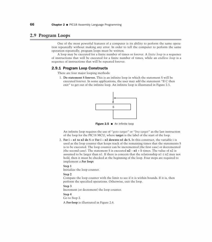
1. Do statement S forever. This is an infinite loop in which the statement S will beexecuted forever. In some applications, the user may add the statement “If C thenexit” to get out of the infinite loop. An infinite loop is illustrated in Figure 2.5.
S
Figure 2.5 � An infinite loop
An infinite loop requires the use of “goto target” or “bra target” as the last instructionof the loop for the PIC18 MCU, where target is the label of the start of the loop.
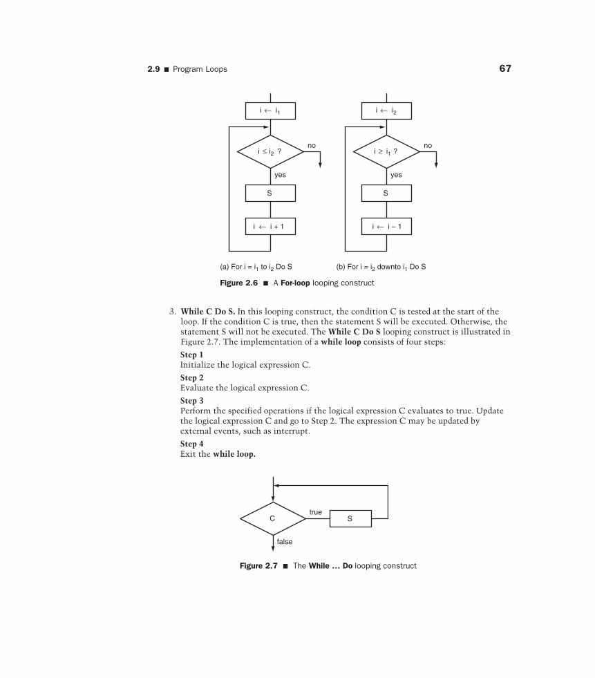
2. For i = n1 to n2 do S or For i = n2 downto n1 do S. In this construct, the variable i isused as the loop counter that keeps track of the remaining times that the statements Sis to be executed. The loop counter can be incremented (the first case) or decremented(the second case). The statement S is executed n2 – n1 + 1 times. The value of n2 isassumed to be larger than n1. If there is concern that the relationship n1 ≤ n2 may nothold, then it must be checked at the beginning of the loop. Four steps are required toimplement a For loop:
Step 1Initialize the loop counter.
Step 2Compare the loop counter with the limit to see if it is within bounds. If it is, thenperform the specified operations. Otherwise, exit the loop.
Step 3Increment (or decrement) the loop counter.
Step 4Go to Step 2.
A For-loop is illustrated in Figure 2.6.
2.9 � Program Loops 67
3. While C Do S. In this looping construct, the condition C is tested at the start of theloop. If the condition C is true, then the statement S will be executed. Otherwise, thestatement S will not be executed. The While C Do S looping construct is illustrated inFigure 2.7. The implementation of a while loop consists of four steps:
Step 1Initialize the logical expression C.
Step 2Evaluate the logical expression C.
Step 3Perform the specified operations if the logical expression C evaluates to true. Updatethe logical expression C and go to Step 2. The expression C may be updated byexternal events, such as interrupt.
Step 4Exit the while loop.
i ← i1
i ≤ i2 ?
S
yes
i ← i + 1
(a) For i = i1 to i2 Do S
no
i ← i2
i ≥ i1 ?
S
yes
i ← i – 1
(b) For i = i2 downto i1 Do S
no
Figure 2.6 � A For-loop looping construct
C Strue
false
Figure 2.7 � The While … Do looping construct
68 Chapter 2 � PIC18 Assembly Language Programming
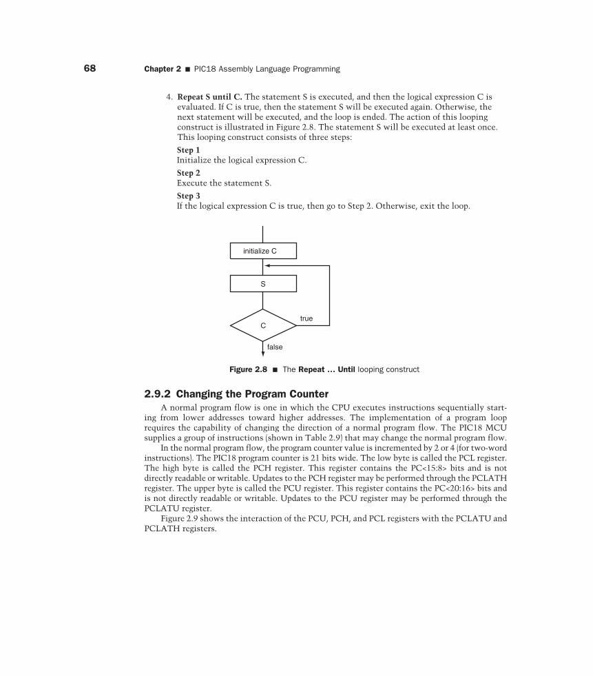
4. Repeat S until C. The statement S is executed, and then the logical expression C isevaluated. If C is true, then the statement S will be executed again. Otherwise, thenext statement will be executed, and the loop is ended. The action of this loopingconstruct is illustrated in Figure 2.8. The statement S will be executed at least once.This looping construct consists of three steps:
Step 1Initialize the logical expression C.
Step 2Execute the statement S.
Step 3If the logical expression C is true, then go to Step 2. Otherwise, exit the loop.
initialize C
S
Ctrue
false
Figure 2.8 � The Repeat … Until looping construct
2.9.2 Changing the Program CounterA normal program flow is one in which the CPU executes instructions sequentially start-
ing from lower addresses toward higher addresses. The implementation of a program looprequires the capability of changing the direction of a normal program flow. The PIC18 MCUsupplies a group of instructions (shown in Table 2.9) that may change the normal program flow.
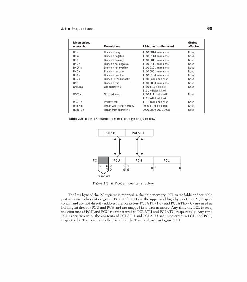
In the normal program flow, the program counter value is incremented by 2 or 4 (for two-wordinstructions). The PIC18 program counter is 21 bits wide. The low byte is called the PCL register.The high byte is called the PCH register. This register contains the PC<15:8> bits and is notdirectly readable or writable. Updates to the PCH register may be performed through the PCLATHregister. The upper byte is called the PCU register. This register contains the PC<20:16> bits andis not directly readable or writable. Updates to the PCU register may be performed through thePCLATU register.
Figure 2.9 shows the interaction of the PCU, PCH, and PCL registers with the PCLATU andPCLATH registers.
2.9 � Program Loops 69
The low byte of the PC register is mapped in the data memory. PCL is readable and writablejust as is any other data register. PCU and PCH are the upper and high bytes of the PC, respec-tively, and are not directly addressable. Registers PCLATU<4:0> and PCLATH<7:0> are used asholding latches for PCU and PCH and are mapped into data memory. Any time the PCL is read,the contents of PCH and PCU are transferred to PCLATH and PCLATU, respectively. Any timePCL is written into, the contents of PCLATH and PCLATU are transferred to PCH and PCU,respectively. The resultant effect is a branch. This is shown in Figure 2.10.
PCLATU PCLATH
PCU PCH PCLPC
23
21
20
16
15
8 7 0
reserved
Figure 2.9 � Program counter structure
Mnemonics, Statusoperands Description 16-bit instruction word affected
BC n Branch if carry 1110 0010 nnnn nnnn NoneBN n Branch if negative 1110 0110 nnnn nnnn NoneBNC n Branch if no carry 1110 0011 nnnn nnnn NoneBNN n Branch if not negative 1110 0111 nnnn nnnn NoneBNOV n Branch if not overflow 1110 0101 nnnn nnnn NoneBNZ n Branch if not zero 1110 0001 nnnn nnnn NoneBOV n Branch if overflow 1110 0100 nnnn nnnn NoneBRA n Branch unconditionally 1110 0nnn nnnn nnnn NoneBZ n Branch if zero 1110 0000 nnnn nnnn NoneCALL n,s Call subroutine 1110 110s kkkk kkkk None
1111 kkkk kkkk kkkkGOTO n Go to address 1110 1111 kkkk kkkk None
1111 kkkk kkkk kkkkRCALL n Relative call 1101 1nnn nnnn nnnn NoneRETLW k Return with literal in WREG 0000 1100 kkkk kkkk NoneRETURN s Return from subroutine 0000 0000 0001 001s None
Table 2.9 � PIC18 instructions that change program flow
70 Chapter 2 � PIC18 Assembly Language Programming
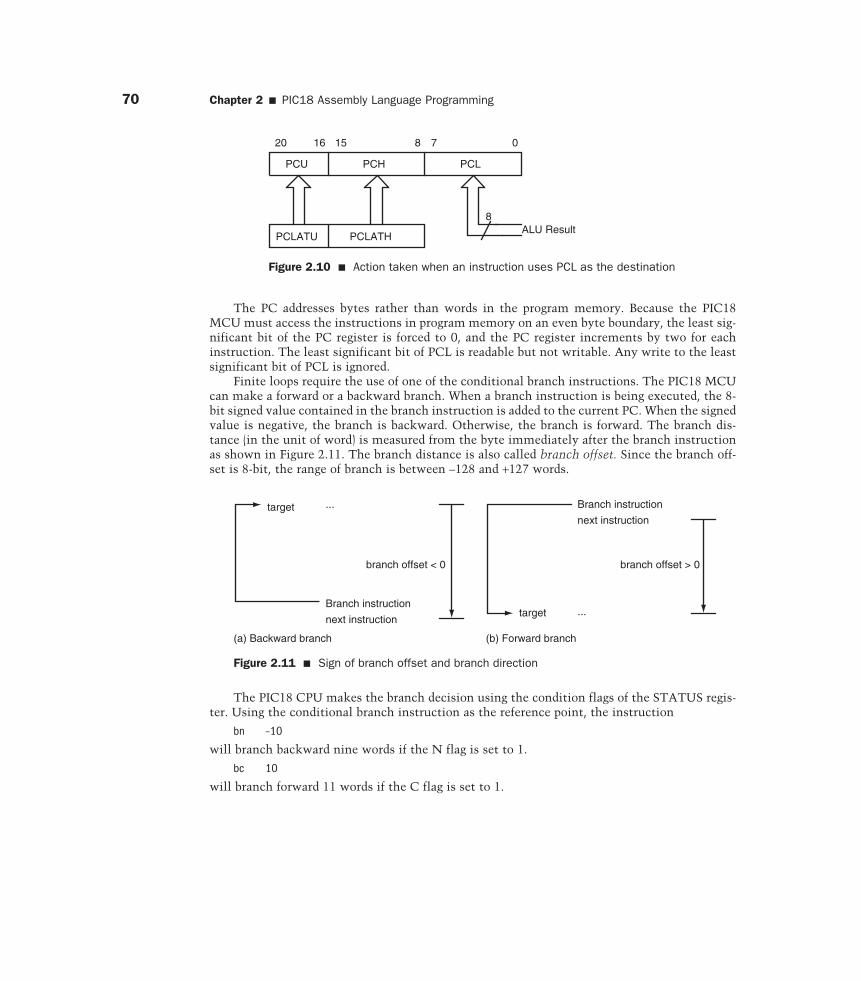
The PIC18 CPU makes the branch decision using the condition flags of the STATUS regis-ter. Using the conditional branch instruction as the reference point, the instruction
bn –10
will branch backward nine words if the N flag is set to 1.
bc 10
will branch forward 11 words if the C flag is set to 1.
Branch instruction
target ...
next instruction
branch offset < 0
(a) Backward branch (b) Forward branch
Branch instruction
next instruction
target ...
branch offset > 0
Figure 2.11 � Sign of branch offset and branch direction
PCU
PCLATU PCLATH
PCH PCL
07820 16 15
8ALU Result
Figure 2.10 � Action taken when an instruction uses PCL as the destination
The PC addresses bytes rather than words in the program memory. Because the PIC18MCU must access the instructions in program memory on an even byte boundary, the least sig-nificant bit of the PC register is forced to 0, and the PC register increments by two for eachinstruction. The least significant bit of PCL is readable but not writable. Any write to the leastsignificant bit of PCL is ignored.
Finite loops require the use of one of the conditional branch instructions. The PIC18 MCUcan make a forward or a backward branch. When a branch instruction is being executed, the 8-bit signed value contained in the branch instruction is added to the current PC. When the signedvalue is negative, the branch is backward. Otherwise, the branch is forward. The branch dis-tance (in the unit of word) is measured from the byte immediately after the branch instructionas shown in Figure 2.11. The branch distance is also called branch offset. Since the branch off-set is 8-bit, the range of branch is between –128 and +127 words.
2.9 � Program Loops 71
Usually, counting the number of words to branch is not very convenient. Therefore, mostassemblers allow the user to use the label of the target instruction to replace the branch offset.For example, the bn –10 can be written as
is_minus . . .. . .bn is_minus
Using the label of the target instruction to replace the branch offset has another advantage:the user does not need to recalculate the branch offset if one or more instructions are added ordeleted between the branch instruction and the target instruction.
The following two instructions are often used to increment or decrement the loop counterand hence update the condition flags:
incf f,d,a ; increment file register fdecf f,d,a ; decrement file register f
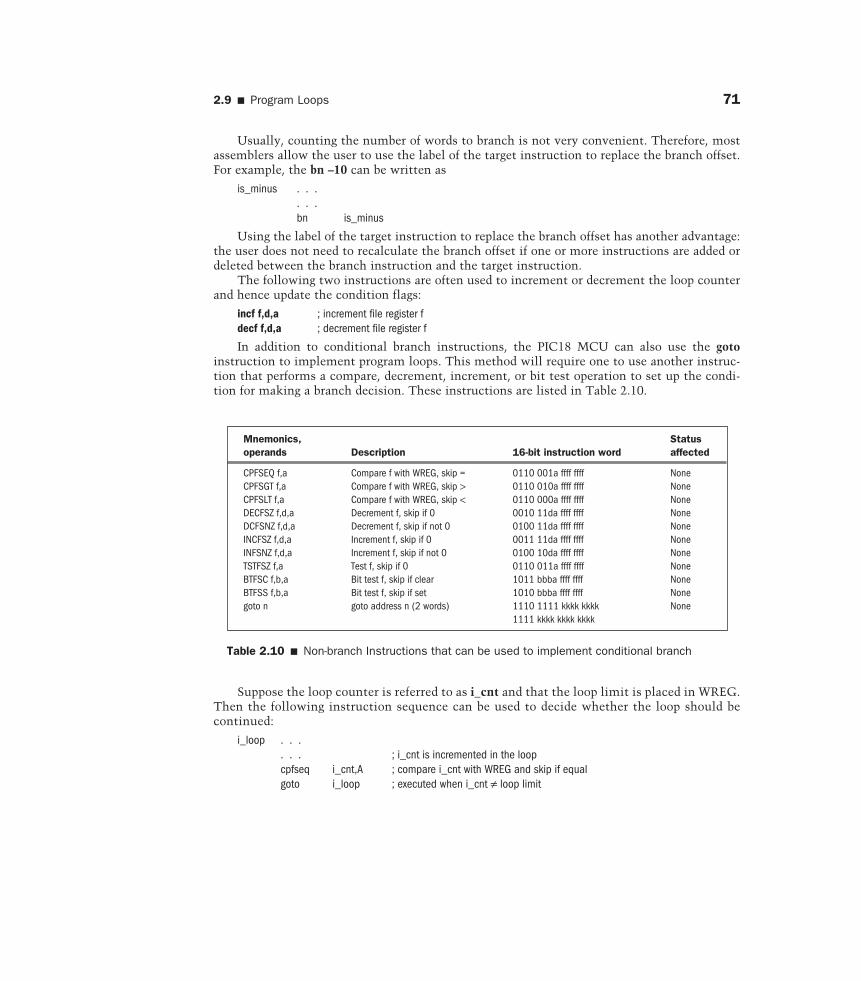
In addition to conditional branch instructions, the PIC18 MCU can also use the gotoinstruction to implement program loops. This method will require one to use another instruc-tion that performs a compare, decrement, increment, or bit test operation to set up the condi-tion for making a branch decision. These instructions are listed in Table 2.10.
Mnemonics, Status operands Description 16-bit instruction word affected
CPFSEQ f,a Compare f with WREG, skip = 0110 001a ffff ffff NoneCPFSGT f,a Compare f with WREG, skip > 0110 010a ffff ffff NoneCPFSLT f,a Compare f with WREG, skip < 0110 000a ffff ffff NoneDECFSZ f,d,a Decrement f, skip if 0 0010 11da ffff ffff NoneDCFSNZ f,d,a Decrement f, skip if not 0 0100 11da ffff ffff NoneINCFSZ f,d,a Increment f, skip if 0 0011 11da ffff ffff NoneINFSNZ f,d,a Increment f, skip if not 0 0100 10da ffff ffff NoneTSTFSZ f,a Test f, skip if 0 0110 011a ffff ffff NoneBTFSC f,b,a Bit test f, skip if clear 1011 bbba ffff ffff NoneBTFSS f,b,a Bit test f, skip if set 1010 bbba ffff ffff Nonegoto n goto address n (2 words) 1110 1111 kkkk kkkk None
1111 kkkk kkkk kkkk
Table 2.10 � Non-branch Instructions that can be used to implement conditional branch
Suppose the loop counter is referred to as i_cnt and that the loop limit is placed in WREG.Then the following instruction sequence can be used to decide whether the loop should becontinued:
i_loop . . .. . . ; i_cnt is incremented in the loopcpfseq i_cnt,A ; compare i_cnt with WREG and skip if equalgoto i_loop ; executed when i_cnt ≠ loop limit
72 Chapter 2 � PIC18 Assembly Language Programming
Suppose that a program loop is to be executed n times. Then the following instructionsequence can do just that:
n equ 20 ;n has the value of 20lp_cnt set 0x10 ; assign file register 0x10 to lp_cnt
. . .movlw nmovwf lp_cnt ; prepare to repeat the loop for n times
loop . . . ; program loop. . . ; “decfsz lp_cnt,F,A ; decrement lp_cnt and skip if equal to 0goto loop ; executed if lp_cnt ≠ 0
If the loop label is within 128 words from the branch point, then one can also use the one-word bra loop instruction to replace the goto loop instruction. The previously mentioned loopcan also be implemented using the bnz loop instruction as follows:
lp_cnt set 0x10 ; use file register 0x10 as lp_cnt. . .movlw nmovwf lp_cnt ; prepare to repeat the loop for n times
loop . . . ; program loop. . . ; “decf lp_cnt,F,A ; decrement lp_cntbnz loop ; executed if lp_cnt ≠ 0
The btfsc f,b,a and btfss f,b,a instructions are often used to implement a loop that waits fora certain flag bit to be cleared or set during an I/O operation. For example, the following instruc-tions will be executed repeatedly until the ADIF bit (bit 6) of the PIR1 register is set to 1:
again btfss PIR1, ADIF,A ; wait until ADIF bit is set to 1bra again
The following instruction sequence will be executed repeatedly until the DONE bit (bit 2)of the ADCON0 register is cleared:
wait_loop btfsc ADCON0,DONE,A ; wait until the DONE bit is clearedbra wait_loop
Example 2.12�
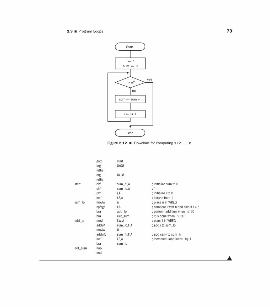
Write a program to compute 1 + 2 + 3 + . . . + n and save the sum at 0x00 and 0x01 assum-ing that the value of n is in a range such that the sum can be stored in two bytes.
Solution: The logic flow for computing the desired sum is shown in Figure 2.12. This flowchartimplements the For i = i1 to i2 Do S loop construct.
The following program implements the algorithm illustrated in Figure 2.12:
#include <p18F8720.inc>n equ D’50’sum_hi set 0x01 ;high byte of sumsum_lo set 0x00 ;low byte of sumi set 0x02 ;loop index i
org 0x00 ;reset vector
2.9 � Program Loops 73
goto startorg 0x08retfieorg 0x18retfie
start clrf sum_hi,A ; initialize sum to 0clrf sum_lo,A ; “clrf i,A ; initialize i to 0incf i,F,A ; i starts from 1
sum_lp movlw n ; place n in WREGcpfsgt i,A ; compare i with n and skip if i > nbra add_lp ; perform addition when i ≤ 50bra exit_sum ; it is done when i > 50
add_lp movf i,W,A ; place i in WREGaddwf sum_lo,F,A ; add i to sum_lomovlw 0addwfc sum_hi,F,A ; add carry to sum_hiincf i,F,A ; increment loop index i by 1bra sum_lp
exit_sum nopend
�
Start
i ← 1
sum ← 0
i > n?
sum ← sum + i
i ← i + 1
yes
no
Stop
Figure 2.12 � Flowchart for computing 1+2+…+n
74 Chapter 2 � PIC18 Assembly Language Programming
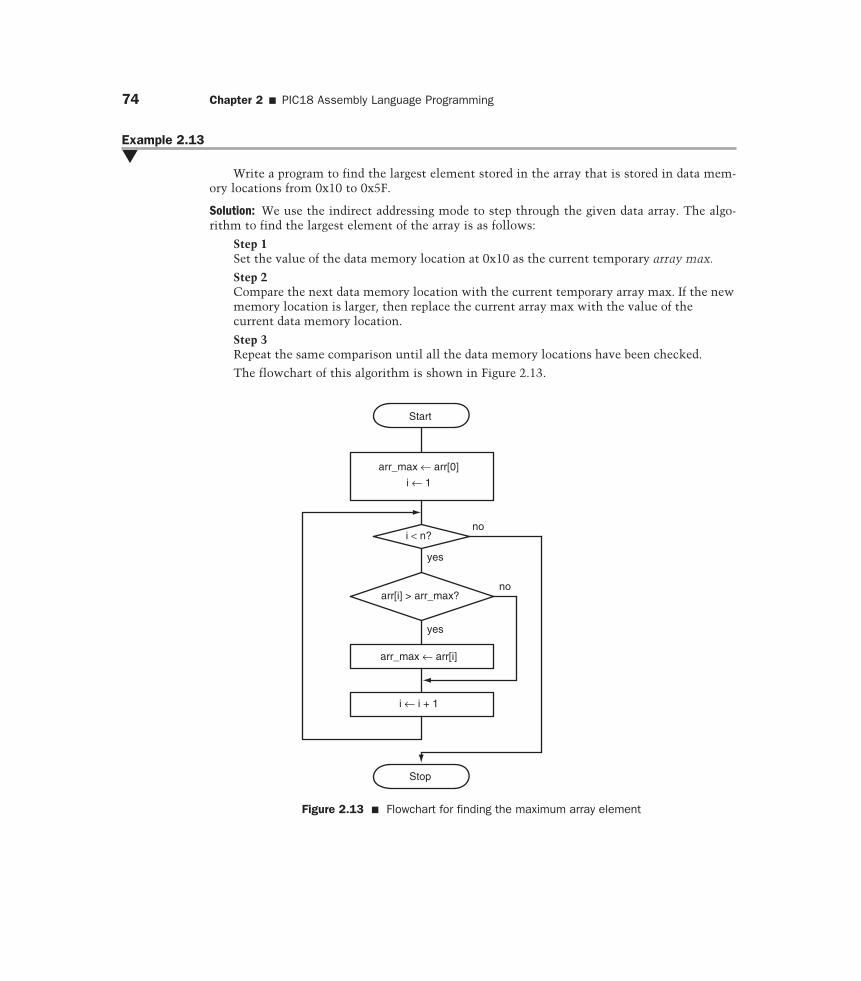
Example 2.13�
Write a program to find the largest element stored in the array that is stored in data mem-ory locations from 0x10 to 0x5F.
Solution: We use the indirect addressing mode to step through the given data array. The algo-rithm to find the largest element of the array is as follows:
Step 1Set the value of the data memory location at 0x10 as the current temporary array max.
Step 2Compare the next data memory location with the current temporary array max. If the newmemory location is larger, then replace the current array max with the value of thecurrent data memory location.
Step 3Repeat the same comparison until all the data memory locations have been checked.
The flowchart of this algorithm is shown in Figure 2.13.
Start
arr_max ← arr[0]
i ← 1
yes
arr[i] > arr_max?
yes
arr_max ← arr[i]
i ← i + 1
Stop
no
no
i < n?
Figure 2.13 � Flowchart for finding the maximum array element
2.10 � Reading and Writing Data in Program Memory 75
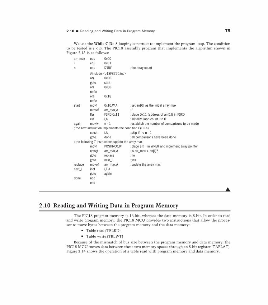
We use the While C Do S looping construct to implement the program loop. The conditionto be tested is i < n. The PIC18 assembly program that implements the algorithm shown inFigure 2.13 is as follows:
arr_max equ 0x00i equ 0x01n equ D’80’ ; the array count
#include <p18F8720.inc>org 0x00goto startorg 0x08retfieorg 0x18retfie
start movf 0x10,W,A ; set arr[0] as the initial array maxmovwf arr_max,A ; “lfsr FSR0,0x11 ; place 0x11 (address of arr[1]) in FSR0clrf i,A ; initialize loop count i to 0
again movlw n - 1 ; establish the number of comparisons to be made; the next instruction implements the condition C(i = n)
cpfslt i,A ; skip if i < n - 1goto done ; all comparisons have been done
; the following 7 instructions update the array maxmovf POSTINC0,W ; place arr[i] in WREG and increment array pointercpfsgt arr_max,A ; is arr_max > arr[i]?goto replace ; nogoto next_i ; yes
replace movwf arr_max,A ; update the array maxnext_i incf i,F,A
goto againdone nop
end
�
2.10 Reading and Writing Data in Program Memory
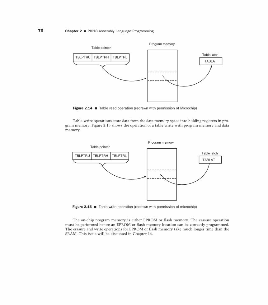
The PIC18 program memory is 16-bit, whereas the data memory is 8-bit. In order to readand write program memory, the PIC18 MCU provides two instructions that allow the proces-sor to move bytes between the program memory and the data memory:
� Table read (TBLRD)� Table write (TBLWT)
Because of the mismatch of bus size between the program memory and data memory, thePIC18 MCU moves data between these two memory spaces through an 8-bit register (TABLAT).Figure 2.14 shows the operation of a table read with program memory and data memory.
76 Chapter 2 � PIC18 Assembly Language Programming
Table-write operations store data from the data memory space into holding registers in pro-gram memory. Figure 2.15 shows the operation of a table write with program memory and datamemory.
Table pointer
TBLPTRU TBLPTRH TBLPTRL
Program memory
Table latch
TABLAT
Figure 2.14 � Table read operation (redrawn with permission of Microchip)
Table pointer
TBLPTRU TBLPTRH TBLPTRL
Program memory
Table latch
TABLAT
Figure 2.15 � Table write operation (redrawn with permission of microchip)
The on-chip program memory is either EPROM or flash memory. The erasure operationmust be performed before an EPROM or flash memory location can be correctly programmed.The erasure and write operations for EPROM or flash memory take much longer time than theSRAM. This issue will be discussed in Chapter 14.
2.10 � Reading and Writing Data in Program Memory 77
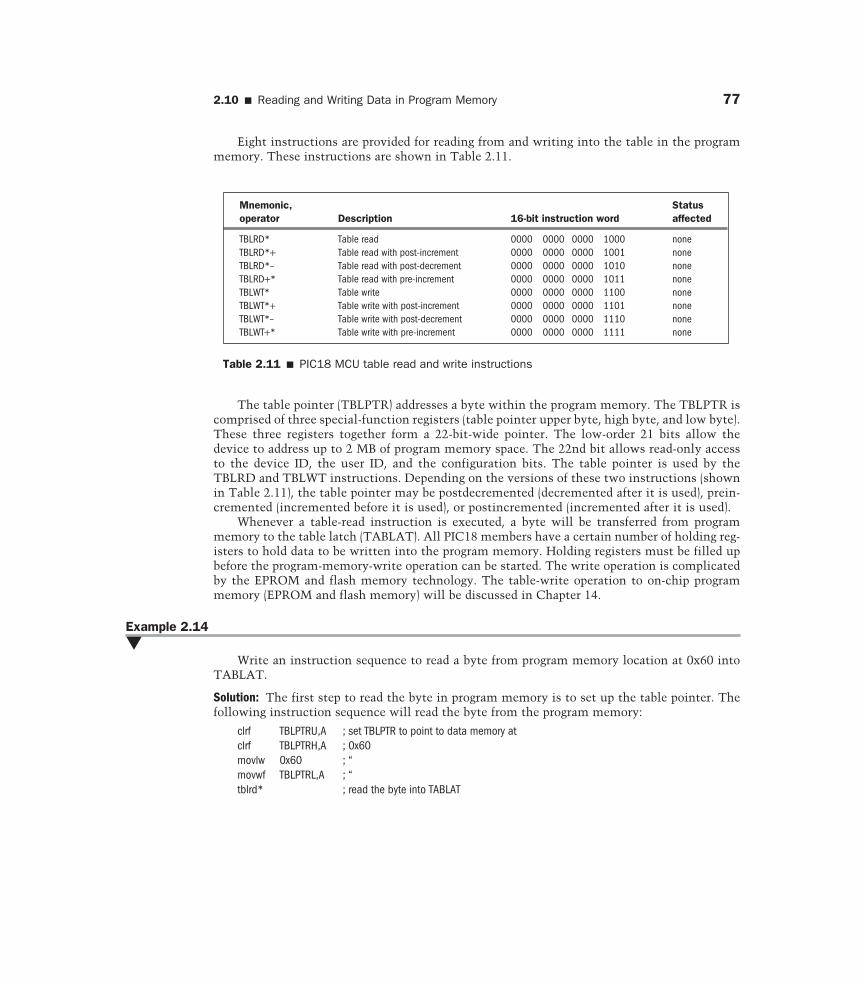
The table pointer (TBLPTR) addresses a byte within the program memory. The TBLPTR iscomprised of three special-function registers (table pointer upper byte, high byte, and low byte).These three registers together form a 22-bit-wide pointer. The low-order 21 bits allow thedevice to address up to 2 MB of program memory space. The 22nd bit allows read-only accessto the device ID, the user ID, and the configuration bits. The table pointer is used by theTBLRD and TBLWT instructions. Depending on the versions of these two instructions (shownin Table 2.11), the table pointer may be postdecremented (decremented after it is used), prein-cremented (incremented before it is used), or postincremented (incremented after it is used).
Whenever a table-read instruction is executed, a byte will be transferred from programmemory to the table latch (TABLAT). All PIC18 members have a certain number of holding reg-isters to hold data to be written into the program memory. Holding registers must be filled upbefore the program-memory-write operation can be started. The write operation is complicatedby the EPROM and flash memory technology. The table-write operation to on-chip programmemory (EPROM and flash memory) will be discussed in Chapter 14.
Example 2.14�
Write an instruction sequence to read a byte from program memory location at 0x60 intoTABLAT.
Solution: The first step to read the byte in program memory is to set up the table pointer. Thefollowing instruction sequence will read the byte from the program memory:
clrf TBLPTRU,A ; set TBLPTR to point to data memory atclrf TBLPTRH,A ; 0x60movlw 0x60 ; “movwf TBLPTRL,A ; “tblrd* ; read the byte into TABLAT
Mnemonic, Status operator Description 16-bit instruction word affected
TBLRD* Table read 0000 0000 0000 1000 noneTBLRD*+ Table read with post-increment 0000 0000 0000 1001 noneTBLRD*– Table read with post-decrement 0000 0000 0000 1010 noneTBLRD+* Table read with pre-increment 0000 0000 0000 1011 noneTBLWT* Table write 0000 0000 0000 1100 noneTBLWT*+ Table write with post-increment 0000 0000 0000 1101 noneTBLWT*– Table write with post-decrement 0000 0000 0000 1110 noneTBLWT+* Table write with pre-increment 0000 0000 0000 1111 none
Table 2.11 � PIC18 MCU table read and write instructions
Eight instructions are provided for reading from and writing into the table in the programmemory. These instructions are shown in Table 2.11.
78 Chapter 2 � PIC18 Assembly Language Programming
In assembly language programming, the programmer often uses a label to refer to an array.The MPASM assembler allows the user to use symbolic names to extract the values of theupper, the high, and the low bytes of a symbol:
� upper name refers to the upper part of name.� high name refers to the middle part of name.� low name refers to the low part of name.
Suppose that the symbol arr_x is the name of an array. Then the following instructionsequence places the address represented by arr_x in the table pointer:
movlw upper arr_xmovwf TBLPTRU,A ; set up the upper part of the table pointermovlw high arr_xmovwf TBLPTRH,A ; set up the middle part of the table pointermovlw low arr_xmovwf TBLPTRL,A ; set up the lower part of the table pointer
�
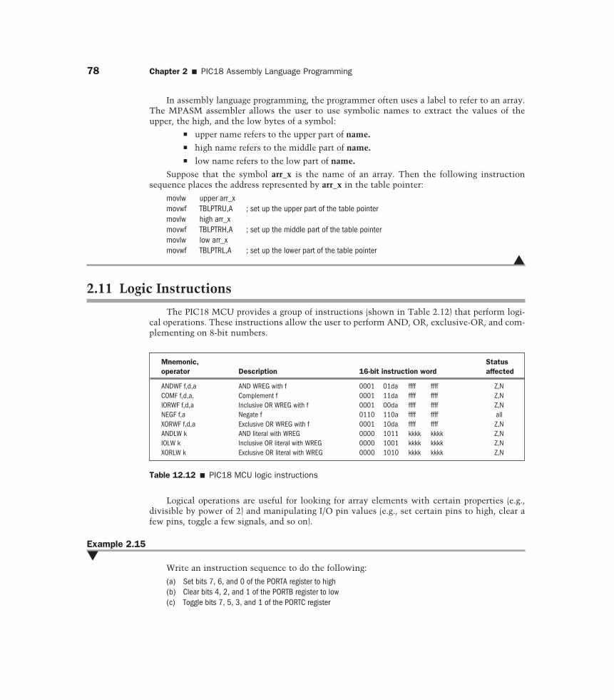
2.11 Logic Instructions
The PIC18 MCU provides a group of instructions (shown in Table 2.12) that perform logi-cal operations. These instructions allow the user to perform AND, OR, exclusive-OR, and com-plementing on 8-bit numbers.
Mnemonic, Status operator Description 16-bit instruction word affected
ANDWF f,d,a AND WREG with f 0001 01da ffff ffff Z,NCOMF f,d,a, Complement f 0001 11da ffff ffff Z,NIORWF f,d,a Inclusive OR WREG with f 0001 00da ffff ffff Z,NNEGF f,a Negate f 0110 110a ffff ffff allXORWF f,d,a Exclusive OR WREG with f 0001 10da ffff ffff Z,NANDLW k AND literal with WREG 0000 1011 kkkk kkkk Z,NIOLW k Inclusive OR literal with WREG 0000 1001 kkkk kkkk Z,NXORLW k Exclusive OR literal with WREG 0000 1010 kkkk kkkk Z,N
Table 12.12 � PIC18 MCU logic instructions
Logical operations are useful for looking for array elements with certain properties (e.g.,divisible by power of 2) and manipulating I/O pin values (e.g., set certain pins to high, clear afew pins, toggle a few signals, and so on).
Example 2.15�
Write an instruction sequence to do the following:
(a) Set bits 7, 6, and 0 of the PORTA register to high(b) Clear bits 4, 2, and 1 of the PORTB register to low(c) Toggle bits 7, 5, 3, and 1 of the PORTC register
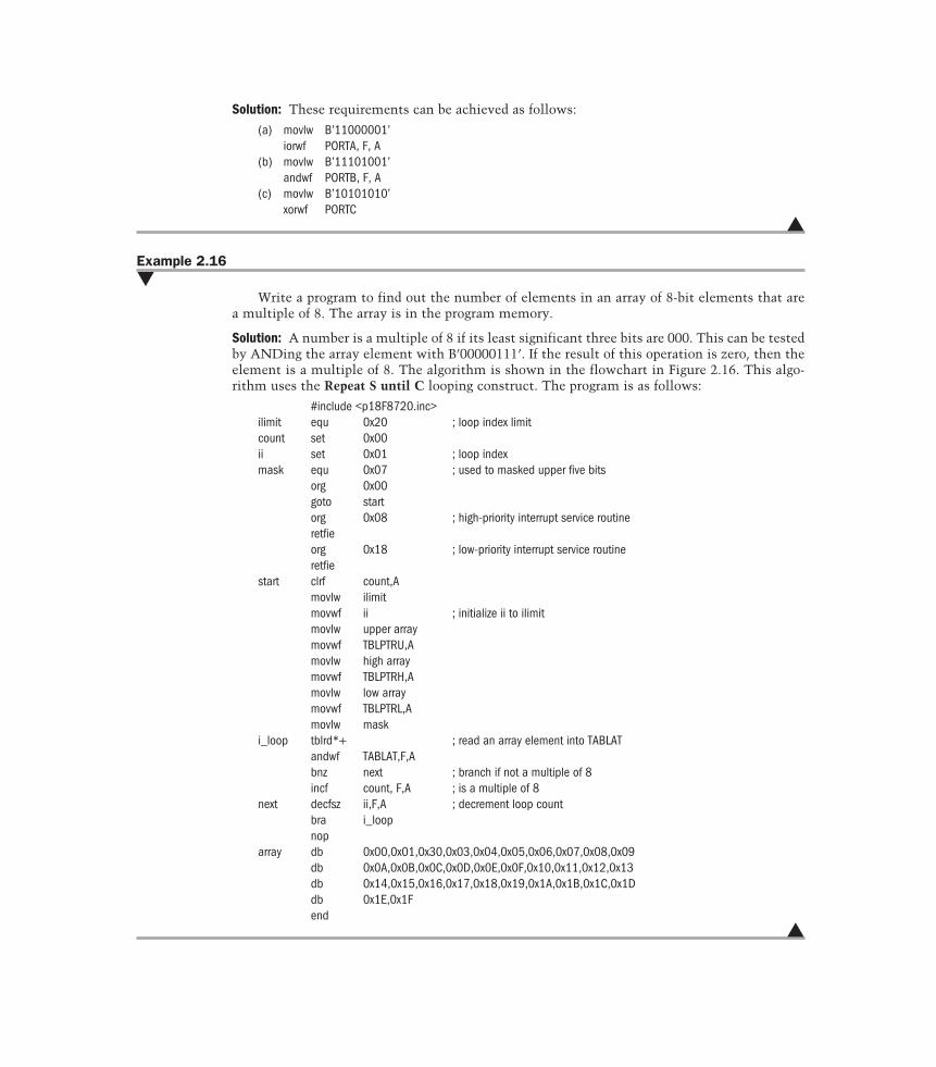
Solution: These requirements can be achieved as follows:
(a) movlw B’11000001’iorwf PORTA, F, A
(b) movlw B’11101001’andwf PORTB, F, A
(c) movlw B’10101010’xorwf PORTC
�
Example 2.16�
Write a program to find out the number of elements in an array of 8-bit elements that area multiple of 8. The array is in the program memory.
Solution: A number is a multiple of 8 if its least significant three bits are 000. This can be testedby ANDing the array element with B’00000111’. If the result of this operation is zero, then theelement is a multiple of 8. The algorithm is shown in the flowchart in Figure 2.16. This algo-rithm uses the Repeat S until C looping construct. The program is as follows:
#include <p18F8720.inc>ilimit equ 0x20 ; loop index limitcount set 0x00ii set 0x01 ; loop indexmask equ 0x07 ; used to masked upper five bits
org 0x00goto startorg 0x08 ; high-priority interrupt service routineretfieorg 0x18 ; low-priority interrupt service routineretfie
start clrf count,Amovlw ilimitmovwf ii ; initialize ii to ilimitmovlw upper arraymovwf TBLPTRU,Amovlw high arraymovwf TBLPTRH,Amovlw low arraymovwf TBLPTRL,Amovlw mask
i_loop tblrd*+ ; read an array element into TABLATandwf TABLAT,F,Abnz next ; branch if not a multiple of 8incf count, F,A ; is a multiple of 8
next decfsz ii,F,A ; decrement loop countbra i_loopnop
array db 0x00,0x01,0x30,0x03,0x04,0x05,0x06,0x07,0x08,0x09db 0x0A,0x0B,0x0C,0x0D,0x0E,0x0F,0x10,0x11,0x12,0x13db 0x14,0x15,0x16,0x17,0x18,0x19,0x1A,0x1B,0x1C,0x1Ddb 0x1E,0x1Fend
�
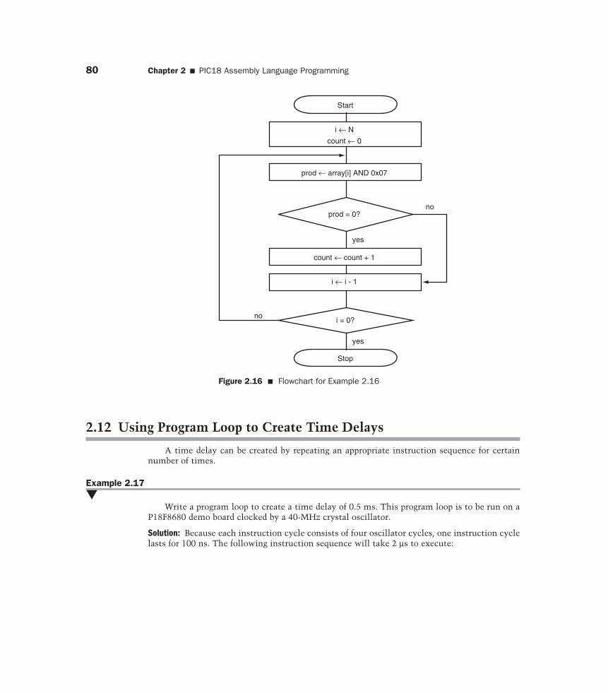
80 Chapter 2 � PIC18 Assembly Language Programming
2.12 Using Program Loop to Create Time Delays
A time delay can be created by repeating an appropriate instruction sequence for certainnumber of times.
Example 2.17�
Write a program loop to create a time delay of 0.5 ms. This program loop is to be run on aP18F8680 demo board clocked by a 40-MHz crystal oscillator.
Solution: Because each instruction cycle consists of four oscillator cycles, one instruction cyclelasts for 100 ns. The following instruction sequence will take 2 µs to execute:
Start
i ← N
count ← 0
prod ← array[i] AND 0x07
prod = 0?
count ← count + 1
yes
no
i = 0?
Stop
yes
no
i ← i - 1
Figure 2.16 � Flowchart for Example 2.16
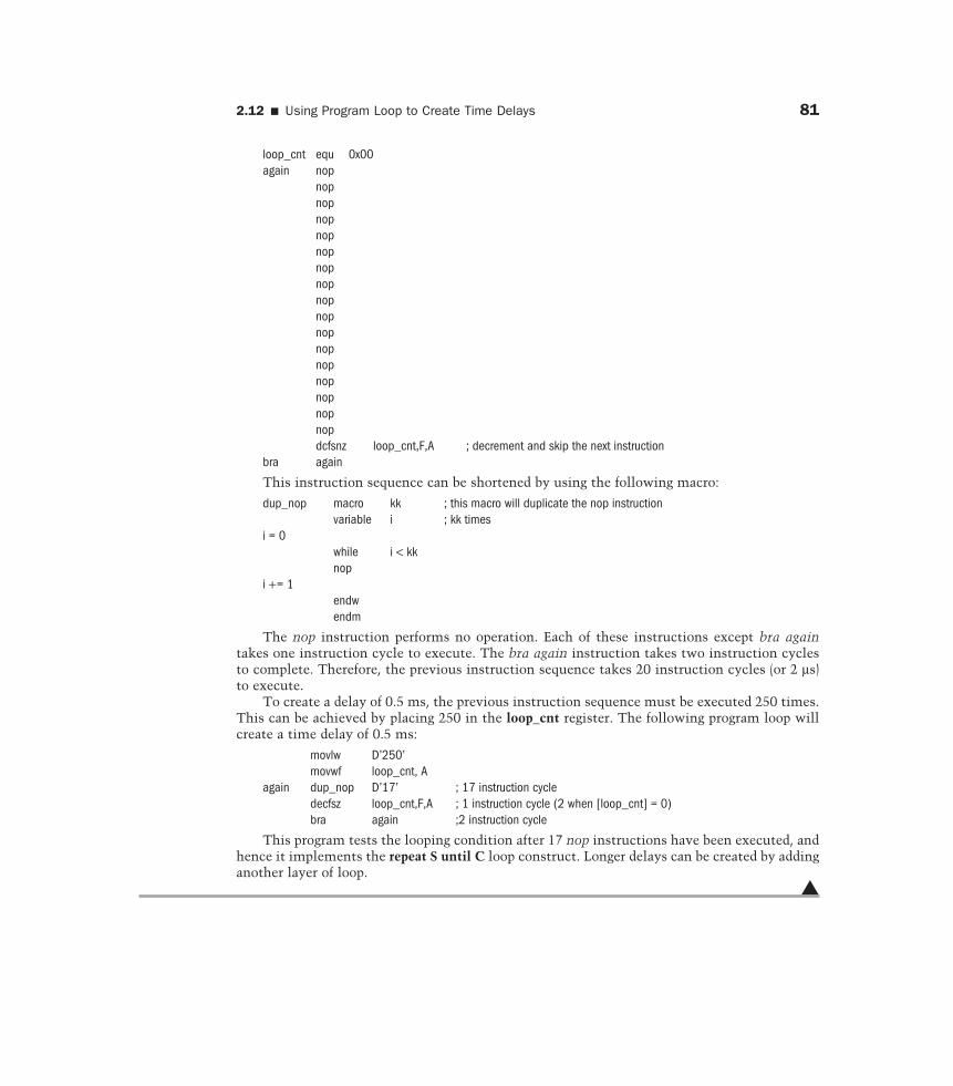
2.12 � Using Program Loop to Create Time Delays 81
loop_cnt equ 0x00again nop
nopnopnopnopnopnopnopnopnopnopnopnopnopnopnopnopdcfsnz loop_cnt,F,A ; decrement and skip the next instruction
bra again
This instruction sequence can be shortened by using the following macro:
dup_nop macro kk ; this macro will duplicate the nop instructionvariable i ; kk times
i = 0while i < kknop
i += 1endwendm
The nop instruction performs no operation. Each of these instructions except bra againtakes one instruction cycle to execute. The bra again instruction takes two instruction cyclesto complete. Therefore, the previous instruction sequence takes 20 instruction cycles (or 2 µs)to execute.
To create a delay of 0.5 ms, the previous instruction sequence must be executed 250 times.This can be achieved by placing 250 in the loop_cnt register. The following program loop willcreate a time delay of 0.5 ms:
movlw D’250’movwf loop_cnt, A
again dup_nop D’17’ ; 17 instruction cycledecfsz loop_cnt,F,A ; 1 instruction cycle (2 when [loop_cnt] = 0)bra again ;2 instruction cycle
This program tests the looping condition after 17 nop instructions have been executed, andhence it implements the repeat S until C loop construct. Longer delays can be created by addinganother layer of loop.
�
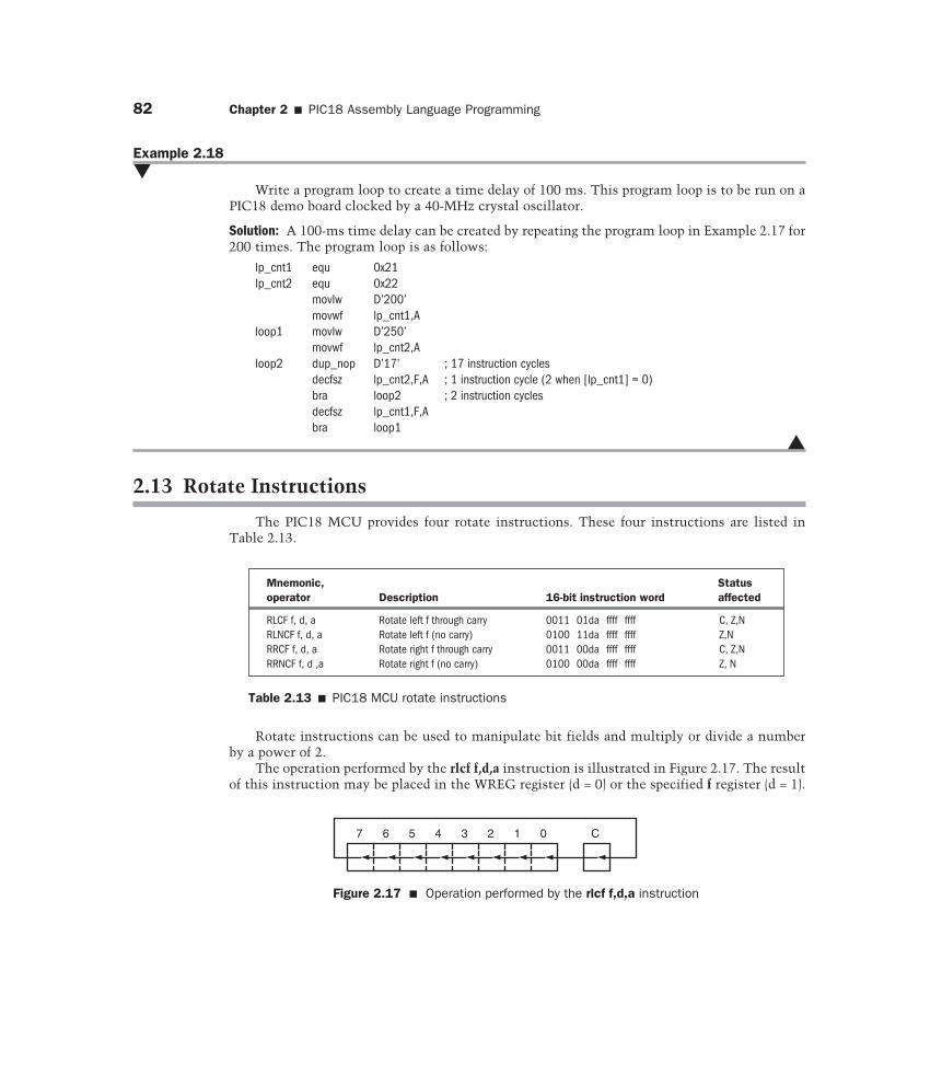
82 Chapter 2 � PIC18 Assembly Language Programming
Example 2.18�
Write a program loop to create a time delay of 100 ms. This program loop is to be run on aPIC18 demo board clocked by a 40-MHz crystal oscillator.
Solution: A 100-ms time delay can be created by repeating the program loop in Example 2.17 for200 times. The program loop is as follows:
lp_cnt1 equ 0x21lp_cnt2 equ 0x22
movlw D’200’movwf lp_cnt1,A
loop1 movlw D’250’movwf lp_cnt2,A
loop2 dup_nop D’17’ ; 17 instruction cyclesdecfsz lp_cnt2,F,A ; 1 instruction cycle (2 when [lp_cnt1] = 0)bra loop2 ; 2 instruction cyclesdecfsz lp_cnt1,F,Abra loop1
�
2.13 Rotate Instructions
The PIC18 MCU provides four rotate instructions. These four instructions are listed inTable 2.13.
Mnemonic, Status operator Description 16-bit instruction word affected
RLCF f, d, a Rotate left f through carry 0011 01da ffff ffff C, Z,NRLNCF f, d, a Rotate left f (no carry) 0100 11da ffff ffff Z,NRRCF f, d, a Rotate right f through carry 0011 00da ffff ffff C, Z,NRRNCF f, d ,a Rotate right f (no carry) 0100 00da ffff ffff Z, N
Table 2.13 � PIC18 MCU rotate instructions
Rotate instructions can be used to manipulate bit fields and multiply or divide a numberby a power of 2.
The operation performed by the rlcf f,d,a instruction is illustrated in Figure 2.17. The resultof this instruction may be placed in the WREG register (d = 0) or the specified f register (d = 1).
7 6 5 4 3 2 1 0 C
Figure 2.17 � Operation performed by the rlcf f,d,a instruction
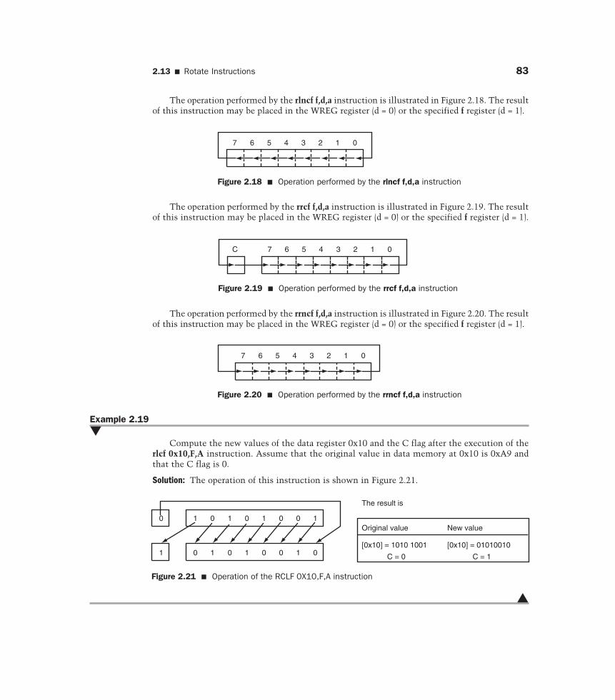
2.13 � Rotate Instructions 83
The operation performed by the rlncf f,d,a instruction is illustrated in Figure 2.18. The resultof this instruction may be placed in the WREG register (d = 0) or the specified f register (d = 1).
7 6 5 4 3 2 1 0
Figure 2.18 � Operation performed by the rlncf f,d,a instruction
7 6 5 4 3 2 1 0C
Figure 2.19 � Operation performed by the rrcf f,d,a instruction
7 6 5 4 3 2 1 0
Figure 2.20 � Operation performed by the rrncf f,d,a instruction
The operation performed by the rrcf f,d,a instruction is illustrated in Figure 2.19. The resultof this instruction may be placed in the WREG register (d = 0) or the specified f register (d = 1).
The operation performed by the rrncf f,d,a instruction is illustrated in Figure 2.20. The resultof this instruction may be placed in the WREG register (d = 0) or the specified f register (d = 1).
Example 2.19�
Compute the new values of the data register 0x10 and the C flag after the execution of therlcf 0x10,F,A instruction. Assume that the original value in data memory at 0x10 is 0xA9 andthat the C flag is 0.
Solution: The operation of this instruction is shown in Figure 2.21.
1 0 1 0 1 10 00
1 0 1 0 1 10 0 0
Original value New value
[0x10] = 1010 1001
C = 0
[0x10] = 01010010
C = 1
The result is
Figure 2.21 � Operation of the RCLF 0X10,F,A instruction
�
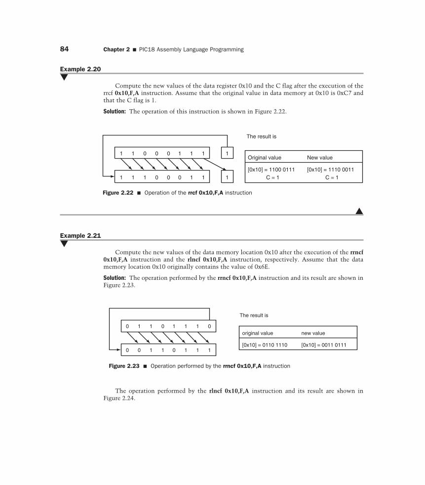
84 Chapter 2 � PIC18 Assembly Language Programming
Example 2.20�
Compute the new values of the data register 0x10 and the C flag after the execution of therrcf 0x10,F,A instruction. Assume that the original value in data memory at 0x10 is 0xC7 andthat the C flag is 1.
Solution: The operation of this instruction is shown in Figure 2.22.
1 1 0 0 0 11 1 1
11 1 1 0 10 0 1
Original value New value
[0x10] = 1100 0111 C = 1
[0x10] = 1110 0011 C = 1
The result is
Figure 2.22 � Operation of the rrcf 0x10,F,A instruction
�
Example 2.21�
Compute the new values of the data memory location 0x10 after the execution of the rrncf0x10,F,A instruction and the rlncf 0x10,F,A instruction, respectively. Assume that the datamemory location 0x10 originally contains the value of 0x6E.
Solution: The operation performed by the rrncf 0x10,F,A instruction and its result are shown inFigure 2.23.
10 1 0 1 1 01
0 10 1 1 0 1 1
original value new value
[0x10] = 0110 1110 [0x10] = 0011 0111
The result is
Figure 2.23 � Operation performed by the rrncf 0x10,F,A instruction
The operation performed by the rlncf 0x10,F,A instruction and its result are shown inFigure 2.24.
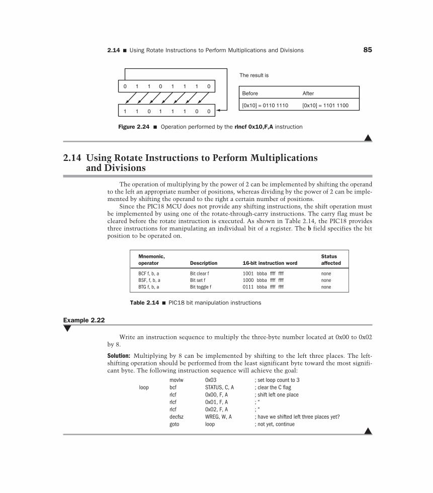
2.14 � Using Rotate Instructions to Perform Multiplications and Divisions 85
10 1 0 1 1 01
1 01 0 1 1 1 0
Before After
[0x10] = 0110 1110 [0x10] = 1101 1100
The result is
Figure 2.24 � Operation performed by the rlncf 0x10,F,A instruction
�
2.14 Using Rotate Instructions to Perform Multiplications and Divisions
The operation of multiplying by the power of 2 can be implemented by shifting the operandto the left an appropriate number of positions, whereas dividing by the power of 2 can be imple-mented by shifting the operand to the right a certain number of positions.
Since the PIC18 MCU does not provide any shifting instructions, the shift operation mustbe implemented by using one of the rotate-through-carry instructions. The carry flag must becleared before the rotate instruction is executed. As shown in Table 2.14, the PIC18 providesthree instructions for manipulating an individual bit of a register. The b field specifies the bitposition to be operated on.
Mnemonic, Status operator Description 16-bit instruction word affected
BCF f, b, a Bit clear f 1001 bbba ffff ffff noneBSF, f, b, a Bit set f 1000 bbba ffff ffff noneBTG f, b, a Bit toggle f 0111 bbba ffff ffff none
Table 2.14 � PIC18 bit manipulation instructions
Example 2.22�
Write an instruction sequence to multiply the three-byte number located at 0x00 to 0x02by 8.
Solution: Multiplying by 8 can be implemented by shifting to the left three places. The left-shifting operation should be performed from the least significant byte toward the most signifi-cant byte. The following instruction sequence will achieve the goal:
movlw 0x03 ; set loop count to 3loop bcf STATUS, C, A ; clear the C flag
rlcf 0x00, F, A ; shift left one placerlcf 0x01, F, A ; “rlcf 0x02, F, A ; “decfsz WREG, W, A ; have we shifted left three places yet?goto loop ; not yet, continue
�
86 Chapter 2 � PIC18 Assembly Language Programming
Example 2.23�
Write an instruction sequence to divide the three-byte number stored at 0x10 to 0x12 by 16.
Solution: Dividing by 16 can be implemented by shifting the number to the right four posi-tions. The right-shifting operation should be performed from the most significant byte towardthe least significant byte. The following instruction sequence will achieve the goal:
movlw 0x04 ; set loop count to 4loop bcf STATUS, C, A ; shift the number to the right 1 place
rrcf 0x12, F, A ; “rrcf 0x11, F, A ; “rrcf 0x10, F, A ; “decfsz WREG, W, A ; have we shifted right four places yet?bra loop ; not yet, continue
�
2.15 Summary
An assembly program consists of three types of statements: assembler directives, assemblylanguage instructions, and comments. An assembler directive tells the assembler how toprocess subsequent assembly language instructions. Directives also provide a way for definingprogram constants and reserving space for dynamic variables. A statement of an assembly pro-gram consists of four fields: label, operation code, operands, and comment.
Although the PIC18 MCU can perform only 8-bit arithmetic operations, numbers that arelonger than eight bits can still be added, subtracted, or multiplied by performing multiprecisionarithmetic. Examples are used to demonstrate multiprecision addition, subtraction, and multi-plication operations.
The multiprecision addition can be implemented with the addwfc f,d,a instruction, andmultiprecision subtraction can be implemented with the subwfb f,d,a instruction. To performmultiprecision multiplication, both the multiplier and the multiplicand must be broken downinto 8-bit chunks. The next step is to generate partial products and align them properly beforeadding them together.
The PIC18 MCU does not provide any divide instruction, and hence a divide operationmust be synthesized.
Performing repetitive operation is the strength of a computer. For a computer to performrepetitive operations, one must write program loops to tell the computer what instructionsequence to repeat. A program loop may be executed a finite or an infinite number of times.There are four looping constructs:
� Do statement S forever� For i = i1 to i2 Do S or For i = i2 downto i1 Do S� While C Do S� Repeat S until C
The PIC18 MCU provides many flow-control and conditional branch instructions forimplementing program loops. Instructions for initializing and updating loop indices and vari-ables are also available.
2.16 � Exercises 87
Rotate instructions are useful for bit-field manipulations. They can also be used to implementmultiplying and dividing a variable by a power of 2. All rotate instructions operate on 8-bit regis-ters only. One can write a sequence of instructions to rotate or shift a number longer than 8 bits.
A PIC18 instruction takes either one or two instruction cycles to complete. By choosing anappropriate instruction sequence and repeating it for a certain number of times, a time delay canbe created.
2.16 Exercises
E2.1 Identify the four fields of the following instructions:
(a) addwf 0x10,W,A ;add register 0x10 to WREG(b) wait btfss STATUS,F,A ; skip the next instruction if the C flag is 1(c) decfsz cnt, F, A ; decrement cnt and skip if it is decremented to 0
E2.2 Find the valid and invalid labels in the following instructions and explain why an invalidlabel is invalid.
column 1↓
a. sum_hi equ 0x20b. low_t incf WREG, W,A ; increment WREG by 1c. abc: movwf 0x30, Ad. 5plus3 clrf 0x33, Ac. _may decf 0x35, F, Af. ?less iorwf 0x1A, F, Ag. two_three goto less
E2.3 Use an assembler directive to define a string “Please make a choice (1/2):” in programmemory.E2.4 Use assembler directives to define a table of all uppercase letters. Place this table in pro-gram memory starting from location 0x2000. Assign one byte to one letter.E2.5 Use assembler directives to assign the symbols sum, lp_cnt, height, and weight to datamemory locations at 0x00, 0x01, 0x02, 0x03, respectively.E2.6 Write an instruction sequence to decrement the contents of data memory locations 0x10,0x11, and 0x12 by 5, 3, and 1, respectively.E2.7 Write an instruction sequence to add the 3-byte numbers stored in memory locations0x11–0x13 and 0x14–0x16 and save the sum in memory locations 0x20–0x22.E2.8 Write an instruction sequence to subtract the 4-byte number stored in memory locations0x10–0x13 from the 4-byte number stored in memory locations 0x00–0x03 and store the differ-ence in memory locations 0x20–0x23.E2.9 Write an instruction sequence to shift the 4-byte number stored in memory locations0x20–0x23 to the right arithmetically four places and leave the result in the same location.E2.10 Write a program to shift the 64-bit number stored in data memory locations 0x10–0x17to the left four places.E2.11 Write an instruction sequence to multiply the 24-bit unsigned numbers stored in datamemory locations 0x10–0x12 and 0x13–0x15 and store the product in data memory locations0x20–0x25.E2.12 Write an instruction sequence to multiply the unsigned 32-bit numbers stored in datamemory locations 0x00–0x03 and 0x04–0x07 and leave the product in data memory memorylocations 0x10–0x17.
88 Chapter 2 � PIC18 Assembly Language Programming
E2.13 Write a program to compute the average of an array of 32 unsigned 8-bit integers stored inthe program memory. Leave the array average in WREG. (Hint, the array contains 32 8-bit num-bers. Therefore, the array average can be computed by using shift operation instead of division.)E2.14 Write an instruction sequence that can extract the bit 6 to bit 2 of the WREG register andstore the resultant value in the lowest five bits of the data register 0x10.E2.15 Write an instruction sequence to create a time delay of 1 second.E2.16 Write an assembly program to count the number of odd elements in an array of n 16-bitintegers. The array is stored in program memory starting from the label arr_x.E2.17 Write a PIC18 assembly program to count the number of elements in an array that aregreater than 20. The array consists of n 8-bit numbers and is stored in program memory start-ing from the label arr_y.E2.18 Write an assembly program to find the smallest element of an array of n 8-bit elements.The array is stored in program memory starting with the label arr_z.E2.19 The sign of a signed number is the most significant bit of that number. A signed numberis negative when its most significant bit is 1. Otherwise, it is positive. Write a program to countthe number of elements that are positive in an array of n 8-bit integers. The array is stored inbank 1 of data memory starting from 0x00.E2.20 Determine the number of times the following loop will be executed:
#include <p18F8720.inc>movlw 0x80
loop bcf STATUS, C, A ; clear the carry flagrrcf WREG, W, Aaddwf WREG, W, A ; add WREG to itselfbtfsc WREG, 7, A ; test bit 7goto loop. . .
E2.21 What will be the value of the carry flag after the execution of each of the followinginstructions? Assume that the WREG register contains 0x79 and that the carry flag is 0 beforethe execution of each instruction.
(a) addlw 0x30(b) addlw 0xA4(c) sublw 0x95(d) sublw 0x40
E2.22 Write a program to compute the average of the squares of 32 8-bit numbers stored in theaccess bank from data memory location 0x00 to 0x1F. Save the average in the data memory loca-tions 0x21–0x22.E2.23 Suppose the contents of the WREG register and the C flag are 0x95 and 1, respectively.What will be the contents of the WREG register and the C flag after the execution of each of thefollowing instructions?
(a) rrcf WREG, W, A(b) rrncf WREG, W, A(c) rlcf WREG, W, A(d) rlncf WREG, W, A
E2.24 Write a program to swap the first element of the array with the last element of the array,the second element with the second-to-last element, and so on. Assume that the array has 20 8-bit elements and is stored in data memory. The starting address of this array is 0x10 in theaccess bank.