PIC Ultra 2 Arduino - WIDE.HK Technologywide.hk/pdf/PIC_Ultra_2_Arduino.pdf · with PIC such as...
35
PIC Development Board Ultra 2 WIDE.HK IC D I P P P PI P IC C P P P P P P P C + Arduino UNO USER'S GUIDE
Transcript of PIC Ultra 2 Arduino - WIDE.HK Technologywide.hk/pdf/PIC_Ultra_2_Arduino.pdf · with PIC such as...

PIC Development Board Ultra 2
WIDE.HK
IC DIPPPPIPPICCPPPPPPPIC+ Arduino UNOUSER'S GUIDE
2 PIC Development Board Ultra 2pa
ge
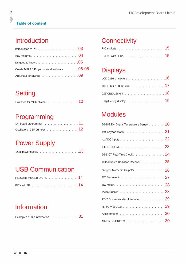
Table of content
WIDE.HK
DS18B20 - Digital Temperature Sensor . . . . . . . . . . . .
LCD 2x16 characters . . . . . . . . . . . . . . . . . . . . . . . . . .
Introduction to PIC . . . . . . . . . . . . . . . . . . . . . . . . . . . .
Stepper Motoer in Unipolar . . . . . . . . . . . . . . . . . . . .
I2C EEPROM . . . . . . . . . . . . . . . . . . . . . . . . . . . . . . .
PIC sockets . . . . . . . . . . . . . . . . . . . . . . . . . . . . . . . .
8 digit 7-seg display . . . . . . . . . . . . . . . . . . . . . . . . . .
4x4 Keypad Matrix. . . . . . . . . . . . . . . . . . . . . . . . . . . .
GLCD KS0108 128x64. . . . . . . . . . . . . . . . . . . . . . . .
Create MPLAB Project + install software. . . . . . . . . .
DS1307 Real-Time Clock . . . . . . . . . . . . .. . . . . . . . .
Full I/O with LEDs . . . . . . . . . . . . . . . . . . . . . . . . . . ..
4x ADC inputs . . . . . . . . . . . . . . . . . . . . . . . . . . . . . .
Dual power supply . . . . . . . . . . . . . . . . . . . . . . . . . . . .
Switches for MCU / Reset . . . . . . . . . . . . . . . . . . . . .
0.96” OLED 128x64 . . . . . . . . . . . . . . . . . . . . . . . . . . . .
IrDA Infrared Radiation Receiver . . . . . . . . . . . . . . . .
Introduction
Power Supply
Setting
Programming
Displays
Modules
Connectivity
20
16
03
26
23
15
19
21
17
06-08
24
15
22
13
10
18
25
PIC UART via USB UART. . . . . . . . . . . . . . . . . . . . . .
PIC via USB . . . . . . . . . . . . . . . . . . . . . . . . . . . . . . . . .
USB Communication14
14
Examples / Chip information . . . . . . . . . . . . . . . . . . .
Information
RC Servo motor . . . . . . . . . . . . . . . . . . . . . . . . . . . . . 27DC motor . . . . . . . . . . . . . . . . . . . . . . . . . . . . . . . . . . 28Piezo Buzzer . . . . . . . . . . . . . . . . . . . . . . . . . . . . . . . 28
PS/2 Communication Interface . . . . . . . . . . . . . . . . . 29
NTSC Video-Out . . . . . . . . . . . . . . . . . . . . . . . . . . . . 29Accelermeter . . . . . . . . . . . . . . . . . . . . . . . . . . . . . . . 30MMC / SD PROTO. . . . . . . . . . . . . . . . . . . . . . . . . . . 30
On-board programmer . . . . . . . . . . . . . . . . . . . . . . . . 11
Arduino & Hardware . . . . . . . . . . . . . . . . . . . . . . . . . . 09
It’s good to know . . . . . . . . . . . . . . . . . . . . . . . . . . . . . 05
Oscillator / ICSP Jumper . . . . . . . . . . . . . . . . . . . . . . . 12
Key features . . . . . . . . . . . . . . . . . . . . . . . . . . . . . . . . 04
31

3 PIC Development Board Ultra 2pa
ge
Introduction to PIC Development Board Ultra 2
WIDE.HK
The PIC Development Board Ultra 2 provided a economy and high performance development environment for students and professional , the development board possess more function for different requirement , and to broaden the current life needed. The PIC is base on CCS environment and a few example for Microchip C18 language to study , we hope you can satisfaction of the develop of the hardware in the future.

4 PIC Development Board Ultra 2pa
ge
Key features
Key Features1. Power supply voltage regulator2. On-board PIC programmer USB module3. External debugger (ICD3) connector / PICKit2/34. USB-UART communication module / Arduino programmer5. PS/2 Keyboard module6. LED I/O switches7. PIC UART jumper8. DC-Motor module 9. Stepper Motor module10. Full PIC16/24 I/O Port11. Reset button / Servo motor 4x12. Modules switches to enable pull-up/pull-down13. 48x LEDs to indicate pins’ logic state14. NTSC module15. 30x PIC Push buttons inputs16. 3-Axis Accelermeter module17. DS1307 real-time clock module
18. IrDA Infrared Radiation Receiver19. DS1820 temperature sensor module20. Speaker module21. I2C 24C16/LC16 EEPROMs22. Keypad 4x423. 3x Oscillator for PIC16*/2424. SD-Card Module with LEDs25. 128x64 graphic LCD display(Or TFT) , 0.96 oLED26. Seven Segment / 16x2 LCD display 27. 4x Touch pad (For additional experiment)28. PIC16 microcontroller sockets29. PIC24 microcontroller sockets (DIP28/40)30. 4x A/D converter inputs31. LCD I/O jumper32. Arduino UNO33. Ext. Port for additional module (eg. Bluetooth)34. 2x LCD Contrast Potentiometer
WIDE.HK
1 2 34
5 6 7 8 9
10
12
13
1114
16
19
1517
18
2021
23
2224 27
25
26 30
2928
3132
28
33
34
Copyright and trademarks Copyright © 2014 WIDE.HKMicrochip and dsPIC are registered marks of Microchip in the USA and other countries. This document applies to PIC Development Ultra 2 hardware revision V6.0

5 PIC Development Board Ultra 2pa
ge
It’s good to know
WIDE.HK
Power supply7–20V AC or 9–25V DC or via USB cable (5V DC)
Board dimensions300 x 188mm (30x18.8cm)
Weight~325g (0.712 lbs)
ModulesUp to 12 Modules for all Testing
The PIC development boards were equipped with PIC16® as the default chip. Now we are giving you standared chip for user, PIC16F877A is the defaultchip of PIC Ultra 2+ , It has 8K bytes of linear program memory, 256 bytes of linear data memory, and support for a power supply from 1.8V to5V. It’s loaded with great modules: 32 General purpose I/O pins, 5 Analog Input pins (AD), 10-bit, up to 8-channel Analog-to-Digital Converter (A/D). It also has pair of CCP, 2 Comparatorsand MSSP modules (which can be either SPI or I2C).
tors).
High Performance, Low Power Atmel®AVR® 8-Bit Microcontroller Family Atmega328P is the default chip of Arduino UNO, it has a 32K bytes flash memory, 1k bytes EEPROM , 20 MIPS Throughputat 20MHz, 23 General purpose I/O pins, 6x PWM Channels, I2C and SPI.
Package contains
PCB color : RED / Purple
Accessories contains
CD-ROM : 1) Manual / Schematics2) Software / Example MCU :
1) PIC16F877A (on-Board) x12) Atmega328 (on-Board) x1
0.96” 128x64 OLED x11602 LCD Display x1
Dupont wire x 20 8 Channel IR Remote
M

6 PIC Development Board Ultra 2pa
ge
Create MPLAB project
WIDE.HK
1) Install MPLAB from CD-ROM Develop Tools of “MPLAB_IDE_8_88 ” *Install MPLAB-X from CD-ROM if possible*2) Install C18 & C30 tools from “Comiler ” folder3) Install CCS_PCWHD_4.1844) Setup the PICkit 2 from CD-ROM5) Click the MPLAB ICON from desktop
6) Click the Project WIZARD
7) Click the “NEXT”
8)Select the PIC Device PIC16F877A or PIC18F46K20
9) Click the “Micrichip C18 Toolsuite
10) Select the ”MPLAB C18 Compiler(mcc18.exe( v3.46) “
and Click ”Next”
Mic
roch
ip M
PLAB
C18F46K20
18.exe( v3.4618.exe( v3.
7 PIC Development Board Ultra 2pa
ge
Create MPLAB project
WIDE.HK
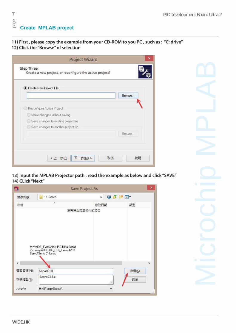
11) First , please copy the example from your CD-ROM to you PC , such as : “C: drive”
12) Click the “Browse” of selection
13) Input the MPLAB Projector path , read the example as below and click “SAVE”
14) CLick “Next”
Mic
roch
ip M
PLAB

8 PIC Development Board Ultra 2pa
ge
Create MPLAB project
WIDE.HK
15) Select your exmaple and “ADD>>” to your created proejct (Example as below)
16) Click the “Next” and “Finished”
15) Successful and you can click the build the output the *.hex file
**PS : (User also can be select the programmer and PICKIT2, BUT IT IS NOT A FULL HARDWARE SUPPORT
FOR ALL PIC DEVICES, so you may need a *.hex file and load from PICKIT2 software after you compiler.)
9 PIC Development Board Ultra 2pa
ge
Arduino & Hardware
WIDE.HK
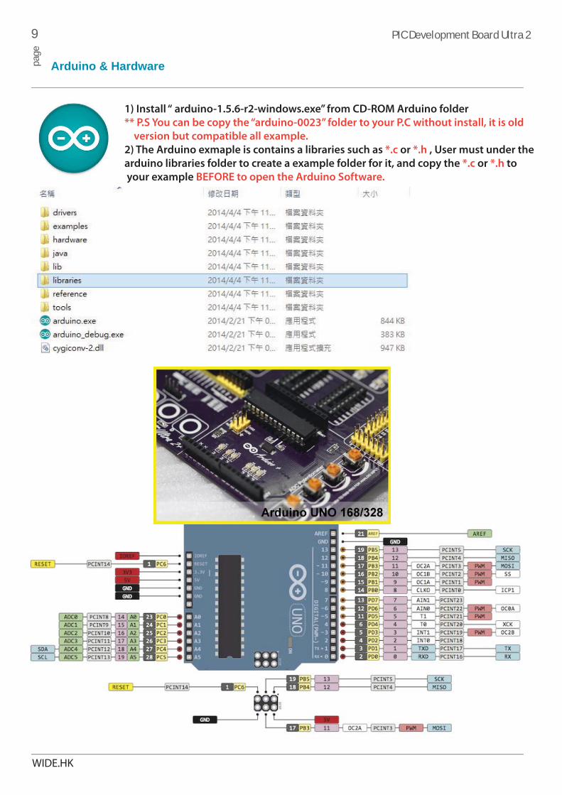
1) Install “ arduino-1.5.6-r2-windows.exe” from CD-ROM Arduino folder
** P.S You can be copy the “arduino-0023” folder to your P.C without install, it is old
version but compatible all example.
2) The Arduino exmaple is contains a libraries such as *.c or *.h , User must under the
arduino libraries folder to create a example folder for it, and copy the *.c or *.h to
your example BEFORE to open the Arduino Software.

10 PIC Development Board Ultra 2pa
ge
Switches for MCU / Reset
WIDE.HK
Reset Button for MCU devices
The switches can connected to MCU with modules when you pull up.
The purpose of the protective resistor is to limit maximum current thus preventing a short circuit from occurring. Just next tothe push buttons, there is a RESET button which is not connected to the MCLR pin.
RB
0R
B1
RA
4R
B4
RA
1R
A0
Vcap
(18J
)VU
SB(R
C3)R
AR
BR
CR
D RE B2
B3
RA
4
To MCU I/O To MCU I/O
RA
0R
A1
RA
2R
A3
RC
0R
C1
RC
2R
C3
To MCU I/O
7 8
To I/O LEDs
7 8
To modules
7 8
To modules
Switch for Devices and I/O
PIC24
PS2(
CLK
)PS
2(D
AT)
NTS
C(O
SC)
NTS
C(O
SC)
DC
mot
or +
1D
C m
otor
+2
Enab
le 1
8F_J
Enab
le U
SB
VR1
(AD
C)
VR2
(AD
C)
VR3
(AD
C)
VR4
(AD
C)
Step
per (
A)
Step
per (
B)
Step
per (
C)
Step
per (
D)
3.3V 5V
RA5VCC28pin
RA540pin
MCU VCC
Switch
Select the voltage for PIC.
[PIC10/12/16/18
VCC
RESET
R55
330R
GND
TO MCU (RESET/MCLR)
R56
10K
VCC
RESET
to Arduino
Switches
Switches have a few function to PIC MCU , such as LEDs , PS2, NTSC, DC Motor, 18F_J, ADC, Stepper and Enable function of PIC USB, so select you needed and pull up.

11 PIC Development Board Ultra 2pa
ge
Programming
WIDE.HK
PIC Chip type selector :
Left (DIP40/28/18)
Right (DIP20/14/8)
USB Module (RX and TX)
How to Connect with Arduino?
Two Programmer available at same time connected
to PC , the black USB can be connected to MCU
directly such as 18F2550 USB interface with UART.
Connected with PIC programmer
**User might need to install UART USB driver, the driver in CD-ROM > develop tools > UART driver
For 32bit : Installer_x86.exeFor 64bit : Installer_x64.exeFor MacOS : USBDriverDisk.dmg
Driver !
ACT (Active) LED lights up when PC is connected.
TX LED lights is send dataRX LED lights is receive data
12 PIC Development Board Ultra 2pa
ge
Oscillator / ICSP jumper
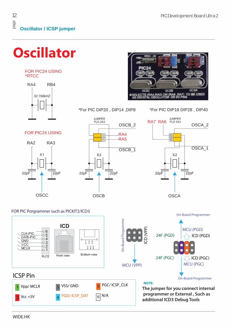
FOR PIC Porgrammer such as PICKIT2/ICD3
Vpp/ MCLR
Vcc +5V
VSS/ GND
PGD/ ICSP_DAT N/A
ICSP Pin
ICD (PGD)
ICD (PGC)
MCU (PGD)
MCU (PGC)
24F (PGD)
24F (PGC)
ICD
(VPP
)
On-Board Programmer
On-Board Programmer
On-
Boar
d Pr
ogra
mm
er
MCU (VPP)
WIDE.HK
RA2 RA3
FOR PIC24 USING RA4RA5
*For PIC DIP20 , DIP14 ,DIP8
OSCB_2
OSCB_1
RA7 RA6
*For PIC DIP18 DIP28 , DIP40
OSCA_2
OSCA_1
OSCC OSCB OSCA
RA4 RB4
FOR PIC24 USING
32.768kHZ
*RTCC
PGC/ ICSP_CLKThe jumper for you connect internal
programmer or External , Such as
additional ICD3 Debug Tools
Oscillator

13 PIC Development Board Ultra 2pa
ge
Power Supply
WIDE.HK
The board can be powered in Two different ways: with USB power supply , or external adapter voltage levels must be in range of 9-12V DC or 9-20V AC. Use switch to specify which power source you are using 5V or 3.3V . Upon providing thepower using either external Supply or USB power source you can turn on power supply by using SWITCH Power LED will indicate the presence of power supply.
Board contains switching power supply that creates stable voltage and current levels necessary forpowering each part of theboard. Power supply section contains two power regulators:MC34063A which generates VCC-5V, and ASM117-3.3 which creates VCC-3.3V power .
0.1uF
C30
0.1uF
C29
VCC 3.3V
GND
* MCU POWER SUPPLY
231
Jumper
TO MCU
For Standard o r nanoWatt XLP
Dual Power
21 3
S WI T
C H1
ON/OFF
Ext Power
1
23
J1
DC 9-20V
V in Vout
GND
U2 ASM1 117-3.34
2
GND
1
23
V in 3.3v
GNDGND
100uF
E30.1uFC19
GND
6 MC34063A
1,7,8
4
GND
220P
C18
GND
3
1
3U3
U1 D2
110uHL2
R36
4.7R
R38
3K
5
0.1uFC20
GND
100uF
E2
GND
GND
100uF
E3
3
1
Supply SelectUSB Power
DC. 5.0vVCC
14 PIC Development Board Ultra 2pa
ge
USBCommunication
WIDE.HK
RC0
RC2
RC1
RC3
RC4
RC5
RC6 RC7
D-
D+
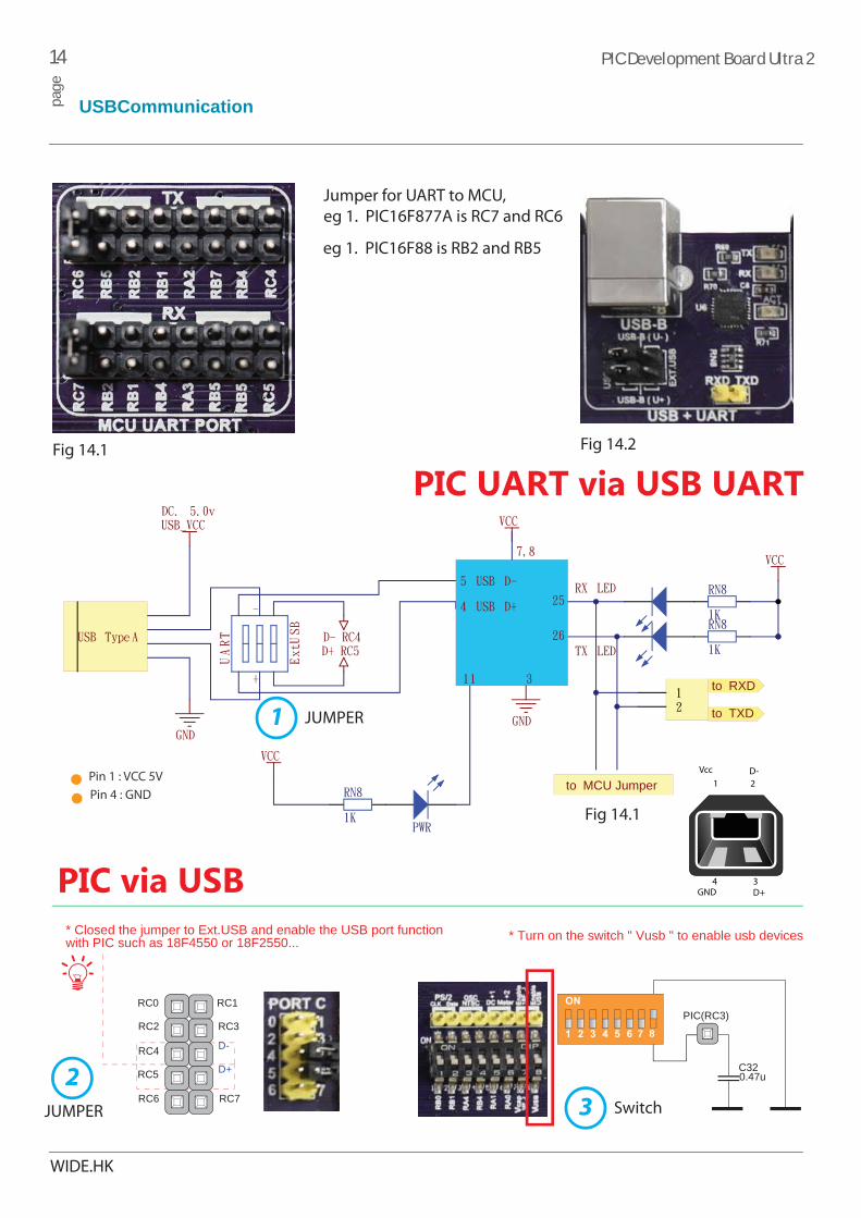
* Closed the jumper to Ext.USB and enable the USB port function with PIC such as 18F4550 or 18F2550...
C32
* Turn on the switch " Vusb " to enable usb devices
7 8
0.47u
PIC(RC3)
4 3
21
GND
Vcc D-
D+
Pin 1 : VCC 5VPin 4 : GND
Jumper for UART to MCU, eg 1. PIC16F877A is RC7 and RC6
eg 1. PIC16F88 is RB2 and RB5
to RXD
RX LED
RN8
1K
VCC
USB Type A
GND
USB_VCC
PWR
RN8
1K
-
+
UART
Ext.USB
D- RC4D+ RC5
VCC
RN8
1K
TX LED
12
DC. 5.0v
GND
VCC
7,8
311
26
25
5 USB D-
4 USB D+
to TXD
to MCU Jumper
JUMPER
Fig 14.1
Fig 14.1
PIC UART via USB UARTFig 14.2
PIC via USB
1
JUMPER
2Switch3

15 PIC Development Board Ultra 2pa
ge
Connectivity
WIDE.HK
The board contains eleven DIP sockets: DIP40, DIP28, DIP20, DIP18A, DIP18B, DIP14, DIP8 and support for PIC10F MCUs. With dual power supply and smart on-board PIC Development board is capable of programming more microcontrollers from PIC10F, PIC12F, PIC16F, PIC18F, PIC18FJ , PIC18FK ,PIC24FJ,PIC24HJ and dsPIC33(28pin) families. There are two DIP18 sockets for PIC microcontrollers provided on the board - DIP18A and DIP18B.
IMPORTANT: When using PIC18F2331 or PIC18F2431 microcontrollers it is necessary to place jumper, in order to route VCC power line to RA5 pin (Figure 15.3)
PORT RB PORT RC PORT RD
PORT RE
PORT RB (For PIC24/33F)
PORT RB (For PIC24/33F)
1K 1K 1K 1K
1K1K
Arduino PWM LEDs
D3
D5
D6
D9
D10
D11
RB15RB14RB13RB12RB11
RB10CapGND
AVdd
RB6
RB7RB8
RB9
GND
RB5
Vdd 3.3vRA4RB4
RA3RA2
GND
RA0RA2RB0RB1RB2RB3
PIC24
C7
C13
C10
C14
C15
C11
C9
C12
RA4B3B2RERDRCRB
PIC24
C12
AVddRB25RB24RB23RB22RB15RB14RB13RB12RB11RB10CapRA8RA7RB9RB8RB7RB6RB5RB21
RB4RA4
Vdd 3.3VRA9RA10RB19RB20
RB3RA16RB17RB18GNDRA2RA3
RA0RA1RB0RB1RB2
R52
AVdd
1K
PIC24
Fig 15.1 Fig 15.2
PIC I/O with LEDS / Arduino PWM LEDs Fig 15.3
44pin(PIC24FJ64GA004) dsPIC33FJ64GP802
16 PIC Development Board Ultra 2pa
ge
LCD 2x16 characters
WIDE.HK
DB0
DB1
DB2
DB3
DB4
DB5
DB6
DB7
CS
RWE
- DATA BUS -
3
VR5
4Bit Data
Controlto PIC
PIC MCU Port
LCD Port
Jumper Setting ::
or Connect to Arduino
Microchip Chip 10k
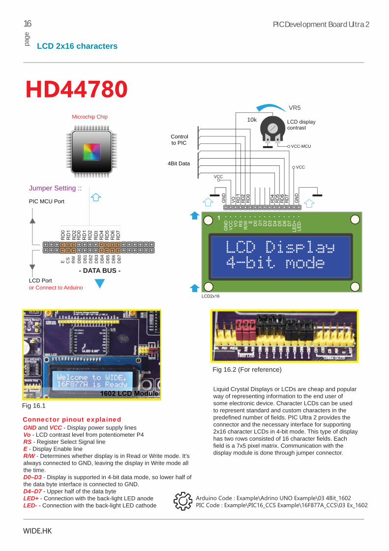
HD44780
Fig 16.1
Fig 16.2 (For reference)
GND and VCC - Display power supply linesVo - LCD contrast level from potentiometer P4RS - Register Select Signal lineE - Display Enable lineR/W - Determines whether display is in Read or Write mode. It’s always connected to GND, leaving the display in Write mode all the time.D0–D3 - Display is supported in 4-bit data mode, so lower half of the data byte interface is connected to GND.D4–D7 - Upper half of the data byteLED+ - Connection with the back-light LED anodeLED- - Connection with the back-light LED cathode
Connector pinout explained
Liquid Crystal Displays or LCDs are cheap and popular way of representing information to the end user of some electronic device. Character LCDs can be used to represent standard and custom characters in the predefined number of fields. PIC Ultra 2 provides the connector and the necessary interface for supporting 2x16 character LCDs in 4-bit mode. This type of display has two rows consisted of 16 character fields. Each field is a 7x5 pixel matrix. Communication with the display module is done through jumper connector.
Arduino Code : Example\Adrino UNO Example\03 4Bit_1602PIC Code : Example\PIC16_CCS Example\16F877A_CCS\03 Ex_1602
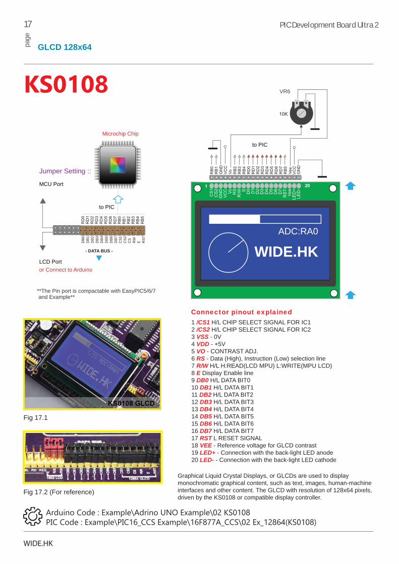
1 /CS1 H/L CHIP SELECT SIGNAL FOR IC12 /CS2 H/L CHIP SELECT SIGNAL FOR IC23 VSS - 0V4 VDD - +5V5 VO - CONTRAST ADJ.6 RS - Data (High), Instruction (Low) selection line7 R/W H/L H:READ(LCD MPU) L:WRITE(MPU LCD)8 E Display Enable line9 DB0 H/L DATA BIT010 DB1 H/L DATA BIT111 DB2 H/L DATA BIT212 DB3 H/L DATA BIT313 DB4 H/L DATA BIT414 DB5 H/L DATA BIT515 DB6 H/L DATA BIT616 DB7 H/L DATA BIT717 RST L RESET SIGNAL18 VEE - Reference voltage for GLCD contrast19 LED+ - Connection with the back-light LED anode20 LED- - Connection with the back-light LED cathode
17 PIC Development Board Ultra 2pa
ge
GLCD 128x64
WIDE.HK
Fig 17.1
ADC:RA0
WIDE.HK
VR6
DB0
DB1
DB2
DB3
DB4
DB5
DB6
DB7
CS1
CS2
CS
RW
E RST
**The Pin port is compactable with EasyPIC5/6/7 and Example**
MCU Port
LCD Port
Jumper Setting ::
- DATA BUS -
to PIC
to PIC
or Connect to Arduino
Microchip Chip
KS0108
Fig 17.2 (For reference)
Connector pinout explained
Graphical Liquid Crystal Displays, or GLCDs are used to display monochromatic graphical content, such as text, images, human-machine interfaces and other content. The GLCD with resolution of 128x64 pixels, driven by the KS0108 or compatible display controller.
Arduino Code : Example\Adrino UNO Example\02 KS0108PIC Code : Example\PIC16_CCS Example\16F877A_CCS\02 Ex_12864(KS0108)

18 PIC Development Board Ultra 2pa
ge
0.96 OLED 128x64
WIDE.HK
D0 D1
D2D3D4
D5D6
D7
CS
WR
RD
RES
Vss
Vss
VccRS
*Microchip PIC18F_ (The Example is SPI mode in CCS, because 16F877A is not enough the RAM)
5v | 3.3v
ICSP
13 1
2 11
10
9
Arduino
RN2810R
RN2810R
RN2810R
RN2810R
R51
1k
(SCLK)(SDIN)
SPI Mode to Arduino
RD7RD0
RE2
RA4
RE1RE0
RA5
Full 8080 I/O Mode to PIC
*Microchip PIC18F_K (The Example is SPI mode in C18)
Demo in SPI for PIC
0.96 OLED Port
The Arduino Example can be plug the OLED module on the port to display the screen as a picture. If for PIC example, user might need to using 7 -wire for connected with a demo for testing, plug and play is not working in microchip (DM164134) C18 demo. The connection as below
1 CS >> RA72 RES >> RA43 RS >> RA54 D0 (SCL) >> RC35 D1 (SDA) >> RC5
6 VCC >> 3.3v / 5v7 GND
Arduino Code : Example\Adrino UNO Example\21 SSD1306 SPI_OLEDPIC Code : Example\PIC18F_C18_Example\01 SPI SSD1306 OLEDPIC CCS is not included. Pls reference Page33(Additional-Chip)
SSD1306

19 PIC Development Board Ultra 2pa
ge
8 digit 7-Seg display
WIDE.HK
A B C D E F G DP
An cathode LED
7-SegmentDIG2DIG1 DIG3 DIG4 DIG5 DIG6 DIG7 DIG8
DIG1 DIG8
A B C D E F G dp 1 2 3 4 5 6 7 8
BC847
Q1 - Q8
DIGRD0 RD1 RD2 RD3 RD4 RD5 RD6 RD7
One seven segment digit consist of 7+1 LEDs which are arranged in a specific formation which can be used to represent digits from 0 to 9 and even some letters. One additional LED is used for marking the decimal dot, in case you want to write a decimal point in the desired segment.
PIC development Ultra 2 contains eight of thesedigits put together to form 8-digit 7-segment display. Driving such a display is done using multiplexing techniques. Data lines are shared between segments, and therefore the same segment LEDs in each digit are connected in parallel. Each digit has it’s unique digit select line.
Arduino Code : Example\Adrino UNO Example\14 SegmentPIC Code : Example\PIC16_CCS Example\16F877A_CCS\14 Ex_Segment
Details : Read a schematics(CD-ROM)

20 PIC Development Board Ultra 2pa
ge
DS18B20 - Digital Temperature Sensor
WIDE.HK
RB0 | RA0R49
DQ
DS1
8B20
The
rmom
eter
The DS18B20 is the digital thermometer from Dallas Semicondutor (Maxim). It communicates with the microcontroller by the 1-Wire® interface. The temperatures from -55°C to 125°C with an accuracy of +/- 0.5°C. The DQ (data pin) is connected to the RA0 OR RB0 pin of the PIC16F877A microcontroller. The data pin should be connected to power supply through 10k pull-up resistor.
How to connect with Arduino?
Pin 2 connect to ouput (DQ)
DS18B20Arduino
ICSP
2 1 0
Arduino
PIC
Fig 20
DS1820 is a digital temperature sensor that uses 1-wire® interface for it’s operation. It is capable of measuring temperatures within the range of -55 to 128°C, and provides ±0.5°C accuracy for temperatures within the range of -10 to 85°C. It requires 3V to 5.5V power supply for stable operation. It takes maximum of 750ms for the DS1820 to calculate temperature with 9-bit resolution. 1-wire® serial communicationenables data to be transferred over a single communication line, while the process itself is under the control of the master microcontroller. The advantage of such communication is that only one microcontroller pin is used. For arduino, connected DS18B20 (DQ)pin to arduino 2 pin, the LCD setting please reference the example code for it.
Arduino Code : Example\Adrino UNO Example\05 DS18B20PIC Code : Example\PIC16_CCS Example\16F877A_CCS\05 Ex_DS18B20_LCD
21 PIC Development Board Ultra 2pa
ge
4x4 Matrix Keypad
WIDE.HK
1 2 3 A
4 5 6 B
7 8 9 C
RB0-3 RB4-7
RN210K
VCC GND
VCC 5V
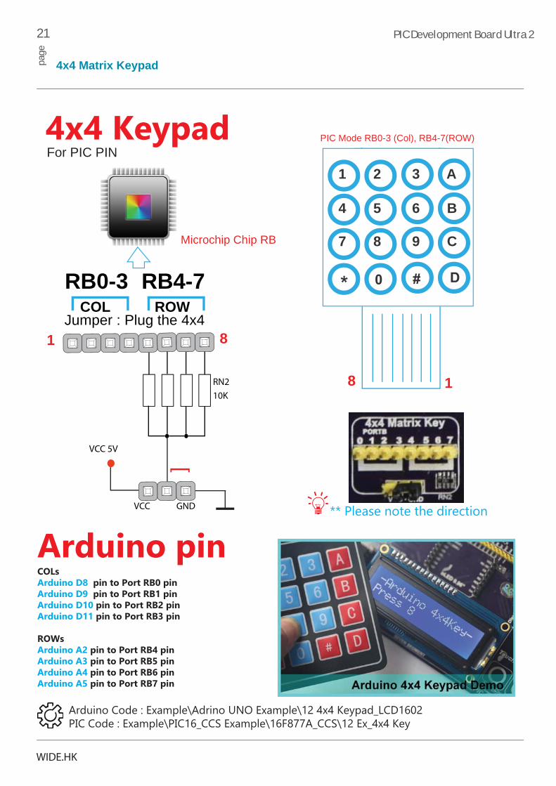
Jumper : Plug the 4x4COL ROW
PIC Mode RB0-3 (Col), RB4-7(ROW)
Microchip Chip RB
[
1
1
8
8
COLs Arduino D8 pin to Port RB0 pin Arduino D9 pin to Port RB1 pin Arduino D10 pin to Port RB2 pin Arduino D11 pin to Port RB3 pin ROWs Arduino A2 pin to Port RB4 pin Arduino A3 pin to Port RB5 pin Arduino A4 pin to Port RB6 pin Arduino A5 pin to Port RB7 pin
Arduino pin** Please note the direction
4x4 KeypadFor PIC PIN
Arduino Code : Example\Adrino UNO Example\12 4x4 Keypad_LCD1602PIC Code : Example\PIC16_CCS Example\16F877A_CCS\12 Ex_4x4 Key

22 PIC Development Board Ultra 2pa
ge
4x ADC inputs
WIDE.HK
RA0~RA3 is A/D input
VCC
VR4
VCC
VR3
VCC
VR2
VCC
VR1
VCC
VR4
VCC
VR3
VCC
VR2
VCC
VR1
RA0~RA3 is A/D input
JUMPER
VCC
VR4
VCC
VR3
VCC
VR2
VCC
VR1
RA0~RA3 is A/D input
JUMPER
JUMPER
DIP40 package and A/D converter test inputs connection DIP28 package and A/D converter test inputs connection
DIP18A package and A/D converter test inputs connection
VCC
VR4
VCC
VR3
VCC
VR2
VCC
VR1
DIP40 package and A/D converter test inputs connection
Analog In
Power In
0 1 2 3 4 5 ICSP
Connected with wire to Arduino Analog in
Digital signals have four discrete states, which are decoded as high and low, and interpreted as logic 1 and logic 0. Analogsignals, on the other hand, are continuous, and can have any value within defined range. A/D converters are specialized circuits which can convert analog signals (voltages) into a digital representation, usually in form of an integer number. The value of this number is linearly dependent on the input voltage value.
The A/D converter built into the microcontroller provided with the PIC development system converts an analog voltage valueinto a10-bit number. Voltages varying from 0V to 5V DC may be supplied through the A/D test inputs in VR0,VR1,VR2 and VR3 for Port RA0 to RA3.
Arduino Code : Example\Adrino UNO Example\06 ADC_LCD1602
PIC Code : Example\PIC16_CCS Example\16F877A_CCS\06 Ex_ADC
ADC

23 PIC Development Board Ultra 2pa
ge
I2C EEPROM
WIDE.HK
24LC16
Vcc : 5V Full Operation16k Bit
16K bit Electrically Erasable PROMs in ISO modules for smart card applications. The device is organ-ized as four or eight blocks of 256 x 8-bit memory with a 2-wire serial interface. The 24LC16 also have a page-write capability for up to 16 bytes of data.
VCC
R634.7K
WP
SDA (RC4 / A4)
A0
A1
A2
GND
SCL (RC3 / A5)
VCC
[ PIC | Arduino ]
R644.7K
EEPROM is short for Electrically Erasable Programmable Read Only Memory. It is usually a secondary storage memory in devices containing data that is retained even if the device looses power supply. Because of the ability to alter single bytes of data, EEPROM devices are used to store personal preference and configuration data in a wide spectrum of consumer, automotive, telecommunication, medical, industrial, and PC applications.
EEPROM which uses I2C communication interface and has16 kbytes of available memory. Board contains socket for serial EEPROMs in DIP8 packaging, so you can easily exchange it with different memory size EEPROM IC.
EEPROM itself supports single byte or 16-byte (page) write and read operations. Data rate is 400 kHz for both 3.3V and 5V power supply.
I2C ™ EEPROMs
Arduino Code : Example\Adrino UNO Example\18 24C16 eepromPIC Code : Example\PIC16_CCS Example\16F877A_CCS\18 Ex_RW_EEprom

24 PIC Development Board Ultra 2pa
ge
DS1307 Real-Time Clock
WIDE.HK
DALLASDS1307
Vcc2
32.768khz VCC
GND
X1
X2
DS1307 64 x 8, Serial, I2C Real-Time Clock
3V CellCR2032
VCC
R61/R624.7K
The DS1307 Serial Real Time Clock is a low power, full BCD clock/calendar plus 56 bytes ofnonvolatile SRAM. Address and data are transferred serially via a 2-wire bi-directional bus. Theclock/calendar provides seconds, minutes, hours, day, date, month, and year information.
SDA (RC4 / A4)
SDL (RC3 / A5)
[ PIC | Arduino ]
The RTC2 Board features the DS1307 serial real-time clock (RTC). It is a low-power, full binary-coded decimal (BCD) clock/calendar plus 56 bytes of NV SRAM. Timekeeping operation continues even when the power supply goes off as it is then powered from the backup supply. It is easily connected to standard prototyping boards. The board comes with the appropriate schematic and software examples.
RTC Clock
Arduino Code : Example\Adrino UNO Example\15 DS1307_LCD1602PIC Code : Example\PIC16_CCS Example\16F877A_CCS\15 Ex_DS1307_LCD_UART

25 PIC Development Board Ultra 2pa
ge
IrDA Infrared Radiation Receiver
WIDE.HK
VCC
GND
Testing the Infrared radiation with 8 channel LED on RB0-RB7 & 10Mhz
IrDA - Infrared radiation Infrared Data Association, a group of device manufacturers that developed a standard for transmitting data via infrared light waves. Increasingly, computers and other devices come with IrDA ports are PortB ,from RB0 to RB7 of 8 channel for LED example.
OUT
Remote 38Khz
RA0
Jumper
*When running the IrDA infrared examplePlease disconnected the button jumper (Fig 25) for All.Even pullup/down , Vcc or GND.
Arduino Example : Remote out = Arduino 8 pin
Microchip Chip RA0
Fig 25.
IrDA
Arduino Code : Example\Adrino UNO Example\08 IrDA ReceiverPIC Code : Example\PIC16_CCS Example\16F877A_CCS\08 Ex_IR Receiver

26 PIC Development Board Ultra 2pa
ge
Stepper Motoer in Unipolar
WIDE.HK
7NI
6NI
5NI
4NI
3NI
2NI
1NI
Out7
Out6
Out5
Out4
Out3
Out2
Out1
Vcc
>>>>
Unipolar Stepper Motor
Vcc1
ABCD +5v ~ 12v+
Coil
}
Vcc}
RC0RC1RC2RC3
R401K
78
Jumper for PIC / Arduino
How to connect with Arduino?
Microchip Chip RC0/1/2/3
Stepper Motor
There are 3 spare darlington pairs on the ULN2003 driver chip, and, with a pull-up resistor for each, these can serve as open-collector inverters to translate one or two switch settings into inputs appropriate for the CounterClockwise or Clockwise. It is support 2 model stepper 5-wire (Fig26.3( 28BYJ-48 step) or 6 wire (Fig26.2) and they are running or step is different.
Fig 26.1
Fig 26.2 Fig 26.3
Arduino Code : Example\Adrino UNO Example\09 Stepper_ULN2003PIC Code : Example\PIC16_CCS Example\16F877A_CCS\09 Ex_Stepper_Motor
27 PIC Development Board Ultra 2pa
ge
RC Servo
WIDE.HK
SIG VCC GND
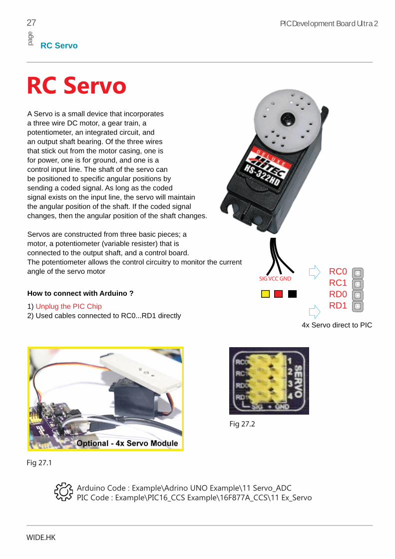
A Servo is a small device that incorporates a three wire DC motor, a gear train, a potentiometer, an integrated circuit, and an output shaft bearing. Of the three wires that stick out from the motor casing, one is for power, one is for ground, and one is a control input line. The shaft of the servo can be positioned to specific angular positions by sending a coded signal. As long as the coded signal exists on the input line, the servo will maintain the angular position of the shaft. If the coded signal changes, then the angular position of the shaft changes.
Servos are constructed from three basic pieces; a motor, a potentiometer (variable resister) that is connected to the output shaft, and a control board. The potentiometer allows the control circuitry to monitor the current angle of the servo motor
4x Servo direct to PIC
RC0RC1RD0RD1
How to connect with Arduino ?
1) Unplug the PIC Chip2) Used cables connected to RC0...RD1 directly
RC Servo
Fig 27.2
Fig 27.1
Arduino Code : Example\Adrino UNO Example\11 Servo_ADCPIC Code : Example\PIC16_CCS Example\16F877A_CCS\11 Ex_Servo

28 PIC Development Board Ultra 2pa
ge
DC Motor / Piezo Buzzer
WIDE.HK
DC-2722
Supply Voltage
GND
Vcc : 5V Full Operation
Supply Voltage for DC 5-12V
VCC
C17100nf
R67
R68
10K
10K
DC Motor
+
-
RA0
RA1
INPUT1
INPUT2
D3
D4
+
-
DC Motor
Fig 28.1 Fig 28.2
The L2722 is monolithic integrated circuits in minidip intended for use as power operational amplifiers in a widerange of applications includingservo amplifiers and power supplies.
Piezo Buzzer
R48
10K
Q112N8050
VCC
BUZZER
RC2
PZ1BUZZER
Jumper
PERSPECTIVEVIEW
TOPVIEW
Buzzer starts "singing" when you provide PWM signal from the microcontroller to the buzzer driver. The pitchof the sound is determined by the frequency, and amplitude is determined by the duty cycle of the PWMsignal.
Arduino Code : Example\Adrino UNO Example\04 BuzzerPIC Code : Example\PIC16_CCS Example\16F877A_CCS\04 Ex_Buzzer
Arduino Code : Example\Adrino UNO Example\10 DC MotorPIC Code : Example\PIC16_CCS Example\16F877A_CCS\10 Ex_DC_Motor

29 PIC Development Board Ultra 2pa
ge
PS2 / NTSC Video
WIDE.HK
The PS/2 connector enables input units, such as keyboard and mouse, to be connected to the development system. In order to enable PS/2 communication, it is necessary to correctly switch to devices, thus connecting DATA and CLK lines to the microcontroller pins RB0 and RB1. Arduino is connect to Jumper and switch off the PS/2.
10k 10k
VCC
Bottom ViewFront View
Jumper
R41 R42
RB0
RB1
PS/2
NTSC Video-Out
2B1A
+
GND
E4100u 16v
R57 75R
BC847
Q10R58 3.3K
R59 3.3K
R60 4.7K
RB10 RB11
VCC
PIC24FJ64GA002
VHFig 29.3
Fig 29.2
Fig 29.1
The NTSC standard for television defines a composite video signal with a refresh rate of 60 half-frames (interlaced) per second. Each frame contains 525 lines and cancontain 16 million different colors. RB10 and RB11 is for frequency.
Arduino Code : Example\Adrino UNO Example\20 NTSC VideoPIC Code : Example\PIC24_C30_Example\03 Ex_PIC24 NTSC-Video
Arduino Code : Example\Adrino UNO Example\19 PS2KeyboardPIC Code : Example\PIC16_CCS Example\16F877A_CCS\19 Ex_PS2_Keyboard

30 PIC Development Board Ultra 2pa
ge
SD PROTO
WIDE.HK
P
P
READY
1KR65
MMC CARD
A MultiMedia Card (MMC) have been superseded by Secure Digital Cards (SD cards) lately, but they are still very popular and widely used because they can be utilized with most devices that support SD cards.The MMC/SD PROTO additional board enables data read/write between a 3.3V microcontroller and MMC/SD cards. Data transfer is performed via a standard Serial Peripheral Interface (SPI).
Arduino Code : Example\Adrino UNO Example\19 PS2KeyboardPIC Code : Example\PIC16_CCS Example\16F877A_CCS\19 Ex_PS2_Keyboard
Accelermeter
ADXL3xxST
X
Y
Z
NC
NC
NC
NCNC
NC
GND GND GND
COM
3.3v 3.3v
VCC
GND
X (RA0)
Y (RA1)
Z (RA2)
ST (SelfTest)
*Module IS NOT Included
VCC
3.3V
5V ST
** Select 3.3V OR 5V for modules(it may damaged if wrong voltage, plese read a datasheet for modules before selected voltage)
XYZ
RA0RA1RA2
The board is a small smart sensorto measure acceleration within a range of 3g of 3 axes. To measureacceleration the Analog Devices ADXL3xx and a PIC16F877A microcontroller is used. The board has a expansion port, which can be used as a digital input and1602 LCD output
Arduino Code : Example\Adrino UNO Example\07 ADXL3xx AccelerometerPIC Code : Example\PIC16_CCS Example\16F877A_CCS\07 EX_ADXL330

31 PIC Development Board Ultra 2pa
ge
Information
WIDE.HK
Information
1) Schematic_1.pdf2) Schematic_2.pdf3) Schematic_3.pdf4) Schematic_4.pdf
Schematics :
Datasheet :1) Chip datasheet2) LCD/GLCD/OLED
1) Arduino Tools2) MPLAB / PICkit2 Tools3) CCS compiler Tools4) UART Tools / Driver
Application :

This product is provided “as is”. ingenia-cat expressly disclaims any warranty of any kind, whether express or implied, including but not limited to, the implied warranties of merchantability, fitness for a particular purpose, or non-infringement.
In no event shall ingenia-cat be liable for any incidental, special, indirect or consequential damages, lost profits or lost data, harm to your equipment, cost of procurement of substitute goods, technology or services, any claims by third parties (including but not limited to any defense thereof), any claims for indemnity or contribution, or other similar costs.
WIDE provides this manual ‘as is’ without warranty of any kind, either expressed or implied, including, but not limited to, the implied warranties or conditions of merchantability or fitnessfor a particular purpose.
The WIDE name and logo, the WIDE logo, PIC Development Board Ultra 2™ are trademarks of WIDE.HK. All other trademarks mentioned herein are property of their respective companies.
All other product and corporate names appearing in this manual may or may not be registered trademarks or copyrights of their respective companies, and are only used for identification or explanation and to the owners’ benefit, with no intent to infringe.
DISCLAIMER
TRADEMARKS
W
Copyright © WIDE.HK™, 2014, All Rights Reserved.
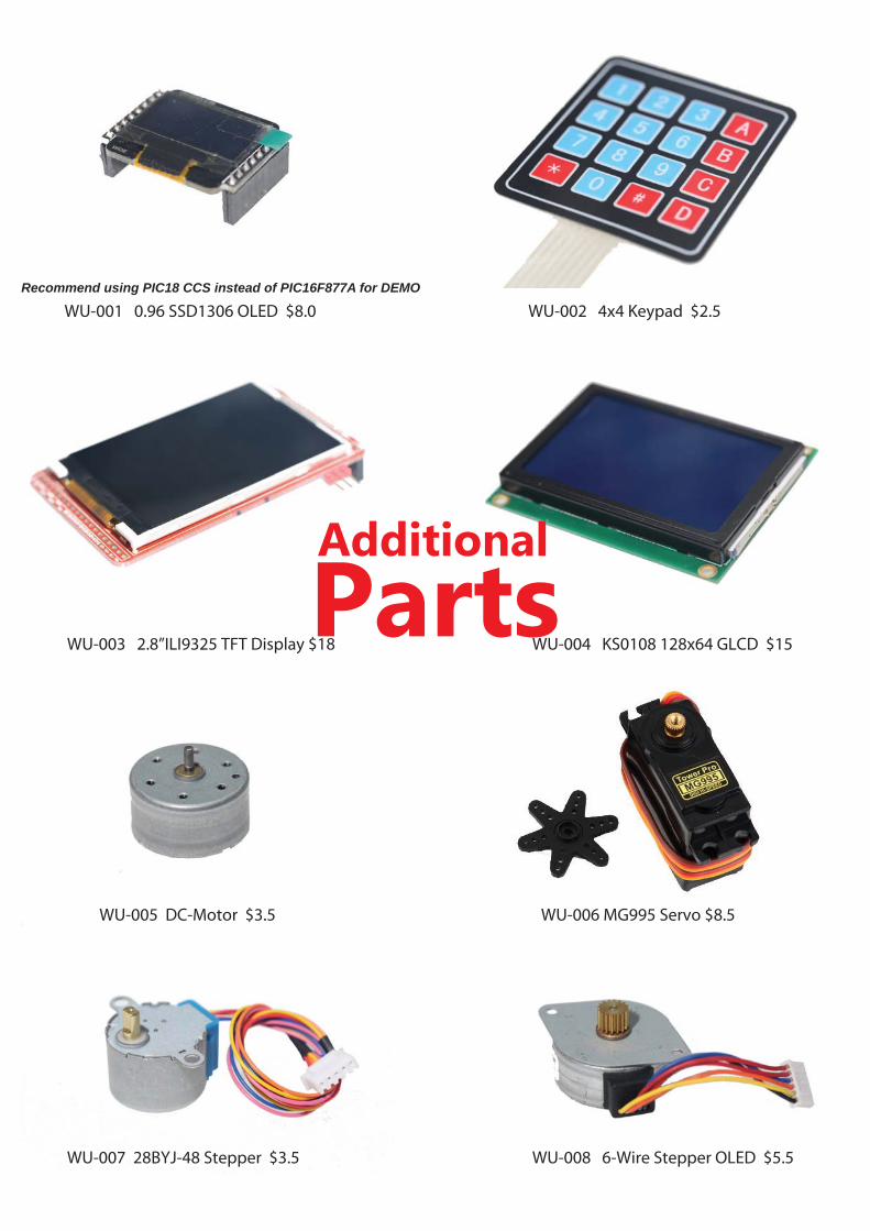
WU-001 0.96 SSD1306 OLED $8.0
PartsAdditional
WU-002 4x4 Keypad $2.5
WU-003 2.8”ILI9325 TFT Display $18 WU-004 KS0108 128x64 GLCD $15
WU-007 28BYJ-48 Stepper $3.5 WU-008 6-Wire Stepper OLED $5.5
WU-005 DC-Motor $3.5 WU-006 MG995 Servo $8.5
Recommend using PIC18 CCS instead of PIC16F877A for DEMO

PIC24FJ64GA004 (40pin) $6.0 Bluetooth Module $9.5
PIC18F4550-DIP $5.0 PIC18F4620-DIP $5.0PIC18F4520-DIP $5.0PIC18F452 -DIP $5.0
PIC18F45K22-DIP $3.5 PIC18F46K20-DIP $3.5PIC18F46K22-DIP $3.5
PIC18F2550-DIP $5.0 PIC24FJ64GA002-DIP $3.5
ChipAdditional
Recommend using PIC18 instead of PIC16F877ARAM size is more than 16F
*
*
For microchip (DM164134) C18 Oled Demo
For 0.96 OLED SPI mode in CCS Demo
PIC Android Module $9.5Ethernet Module coming soon...

note :
WIDE.HK