PIC microcontroller - Feb10 03 v2 - MDM-1 · nThe compiler will generate code to jump to the ISR...
33
16-778/18-778 Mechatronic Design G. Fedder / J. Dolan / R. Grabowski / L. Navarro-Serment, S-02 PIC Functionality n General I/O n Dedicated Interrupt n Change State Interrupt n Input Capture n Output Compare n PWM n ADC n RS232
Transcript of PIC microcontroller - Feb10 03 v2 - MDM-1 · nThe compiler will generate code to jump to the ISR...
16-778/18-778 Mechatronic Design G. Fedder / J. Dolan / R. Grabowski / L. Navarro-Serment, S-02
PIC Functionality
n General I/On Dedicated Interruptn Change State Interruptn Input Capturen Output Comparen PWMn ADC n RS232
16-778/18-778 Mechatronic Design G. Fedder / J. Dolan / R. Grabowski / L. Navarro-Serment, S-02
General I/O
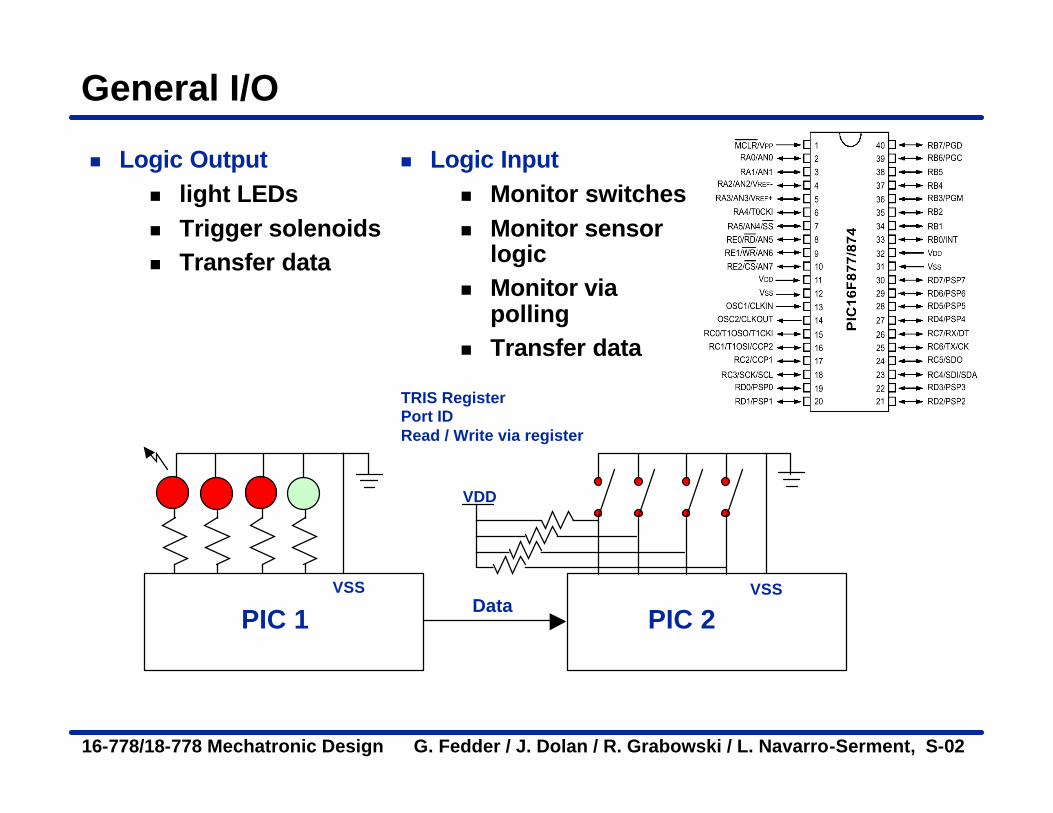
n Logic Outputn light LEDsn Trigger solenoidsn Transfer data
n Logic Inputn Monitor switchesn Monitor sensor
logicn Monitor via
pollingn Transfer data
TRIS RegisterPort IDRead / Write via register
PIC 1 PIC 2Data
VSS
VDD
VSS

16-778/18-778 Mechatronic Design G. Fedder / J. Dolan / R. Grabowski / L. Navarro-Serment, S-02
Interruptsn Program may be interrupted by
external events which have a sense of urgencyn resetn power failuren servicing external eventsn timing for external inputs
Operate on data
Read from sensors, serial port
Output to actuators, display
Service subroutine
Externalevent?
Interrupt program
yes
no
Continueprogram
16-778/18-778 Mechatronic Design G. Fedder / J. Dolan / R. Grabowski / L. Navarro-Serment, S-02
Interrupts
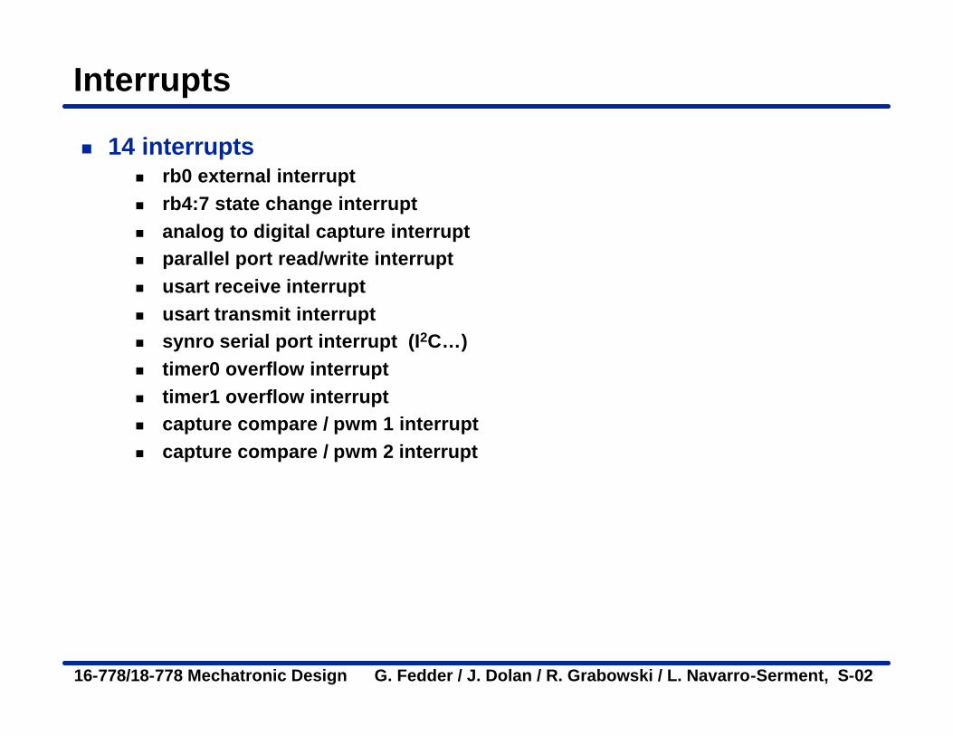
n 14 interruptsn rb0 external interrupt n rb4:7 state change interrupt n analog to digital capture interrupt n parallel port read/write interruptn usart receive interrupt n usart transmit interrupt n synro serial port interrupt (I2C…)n timer0 overflow interruptn timer1 overflow interruptn capture compare / pwm 1 interrupt n capture compare / pwm 2 interrupt
16-778/18-778 Mechatronic Design G. Fedder / J. Dolan / R. Grabowski / L. Navarro-Serment, S-02
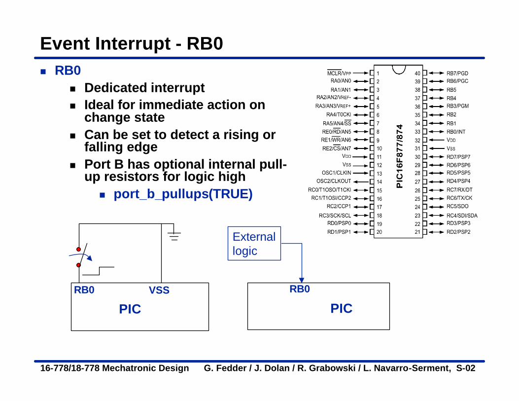
Event Interrupt - RB0n RB0
n Dedicated interruptn Ideal for immediate action on
change staten Can be set to detect a rising or
falling edgen Port B has optional internal pull-
up resistors for logic highn port_b_pullups(TRUE)
PIC PIC
Externallogic
RB0RB0 VSS
16-778/18-778 Mechatronic Design G. Fedder / J. Dolan / R. Grabowski / L. Navarro-Serment, S-02
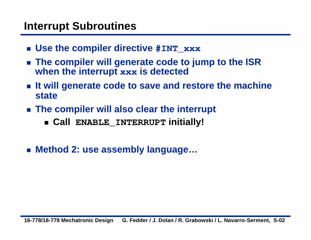
Interrupt Subroutines
n Use the compiler directive #INT_xxxn The compiler will generate code to jump to the ISR
when the interrupt xxx is detectedn It will generate code to save and restore the machine
staten The compiler will also clear the interrupt
n Call ENABLE_INTERRUPT initially!
n Method 2: use assembly language…

16-778/18-778 Mechatronic Design G. Fedder / J. Dolan / R. Grabowski / L. Navarro-Serment, S-02
Digital I/O with interrupts
n Port B can be set to generate interrupts when individual pins RB4:RB7 changen Pins must be configured as inputs can cause this
interrupt to occurn You must write an interrupt service routine to
handle the interrupt
#INT_RBPortb_Change_ISR() {if(seconds!=100) {
++events;printf(“%u chickens. \n”,events);
}}
More on this part later...
16-778/18-778 Mechatronic Design G. Fedder / J. Dolan / R. Grabowski / L. Navarro-Serment, S-02
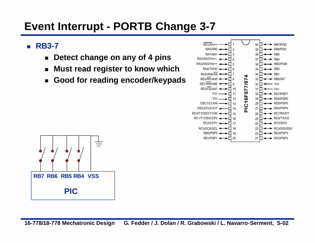
Event Interrupt - PORTB Change 3-7
n RB3-7n Detect change on any of 4 pinsn Must read register to know whichn Good for reading encoder/keypads
PIC
RB7 VSSRB6 RB5 RB4

16-778/18-778 Mechatronic Design G. Fedder / J. Dolan / R. Grabowski / L. Navarro-Serment, S-02
RB3-7
enable_interrupts(GLOBAL); enable_interrupts(INT_RB);
#int_rb rb_isr ( ) {
byte changes; changes = last_b ^ port_b; last_b = port_b; if (bit_test(changes,4 )&& !bit_test(last_b,4)){
//b4 went low } if (bit_test(changes,5)&& !bit_test (last_b,5)){
//b5 went low } . . . delay-ms (100);
}
Need to read port and compare to previous value to know which pins have changed
Enable this interrupt
Define the interrupt
Can test for change pins by masking
PIC
RB7 VSSRB6 RB5 RB4
16-778/18-778 Mechatronic Design G. Fedder / J. Dolan / R. Grabowski / L. Navarro-Serment, S-02
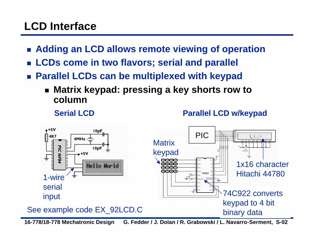
LCD Interface
n Adding an LCD allows remote viewing of operation n LCDs come in two flavors; serial and paralleln Parallel LCDs can be multiplexed with keypad
n Matrix keypad: pressing a key shorts row to column
See example code EX_92LCD.C
Serial LCD Parallel LCD w/keypad
PIC
1x16 characterHitachi 44780
Matrix keypad
74C922 converts keypad to 4 bit binary data
1-wire serial input

16-778/18-778 Mechatronic Design G. Fedder / J. Dolan / R. Grabowski / L. Navarro-Serment, S-02
Interrupt Handling
n When an interrupt is responded to, the GIE is cleared to disable any further interrupt, the return address is pushed onto the stack and the PC is loaded with 0004h.
n Once in the interrupt service routine, the source(s) of the interrupt can be determined by polling the interrupt flag bits.
n The interrupt flag bit(s) must be cleared in software before re-enabling interrupts to avoid recursive interrupts.
16-778/18-778 Mechatronic Design G. Fedder / J. Dolan / R. Grabowski / L. Navarro-Serment, S-02
Ok; turn it on. Is it working…?
n Implement routines to debug your circuitn Use test points to signal eventsn Use the RS232 port to display variables, status, state of
the circuit, etc.n Use LEDs, buzzers, LCD displays, etc.n A diagnostic connector is not a bad idea…
16-778/18-778 Mechatronic Design G. Fedder / J. Dolan / R. Grabowski / L. Navarro-Serment, S-02
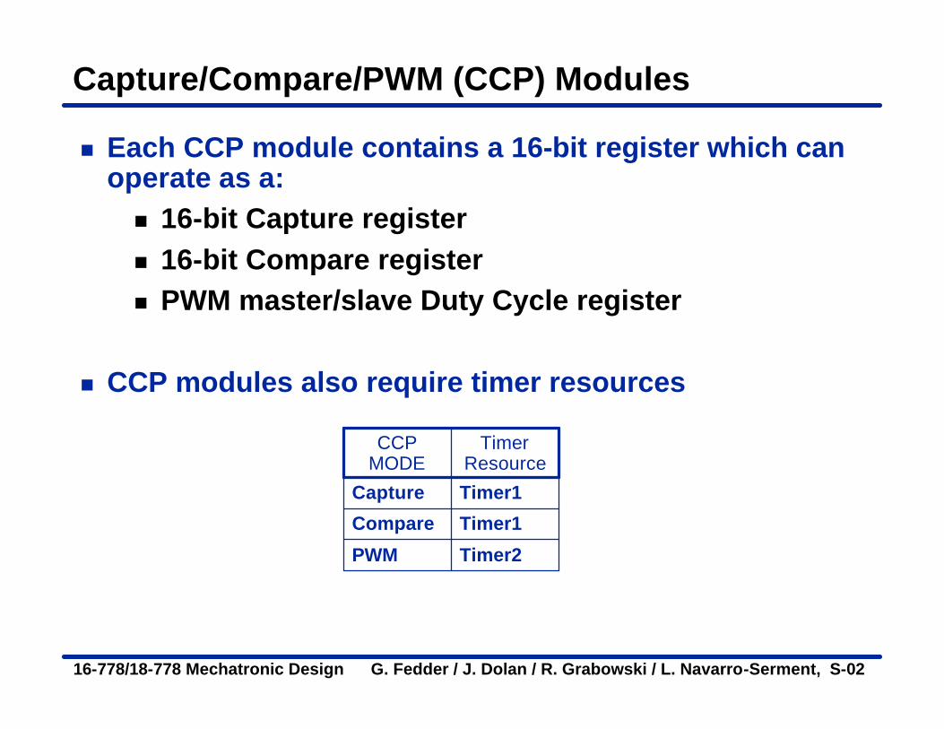
Capture/Compare/PWM (CCP) Modules
n Each CCP module contains a 16-bit register which can operate as a:n 16-bit Capture registern 16-bit Compare registern PWM master/slave Duty Cycle register
n CCP modules also require timer resources
Timer2PWM
Timer1Compare
Timer1Capture
Timer Resource
CCP MODE
16-778/18-778 Mechatronic Design G. Fedder / J. Dolan / R. Grabowski / L. Navarro-Serment, S-02
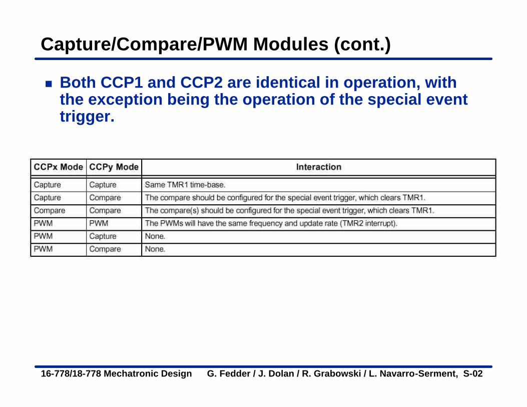
Capture/Compare/PWM Modules (cont.)
n Both CCP1 and CCP2 are identical in operation, with the exception being the operation of the special event trigger.

16-778/18-778 Mechatronic Design G. Fedder / J. Dolan / R. Grabowski / L. Navarro-Serment, S-02
Input Capture
n Input Capturen Measure timing of external eventn Trigger when pin changes staten Trigger stores current timer valuen Utilizes timer 1
PIC 1
Start event (ping)
Receive echo
Use Input capture to detect time until echo occurs
Ultrasonic Emitter
Ultrasonic Receiver

16-778/18-778 Mechatronic Design G. Fedder / J. Dolan / R. Grabowski / L. Navarro-Serment, S-02
Using Input Capture
n In Capture mode, CCPR1H:CCPR1L captures the 16-bit value of the TMR1 register when an event occurs
n An event is defined as:n Every falling edge = CCP_CAPTURE_FEn Every rising edge = CCP_CAPTURE_REn Every 4th rising edge = CCP_CAPTURE_DIV4n Every 16th rising edge = CCP_CAPTURE_DIV16
n Use this if you wantto precisely time the rising and/or falling edge of a digital input
16-778/18-778 Mechatronic Design G. Fedder / J. Dolan / R. Grabowski / L. Navarro-Serment, S-02
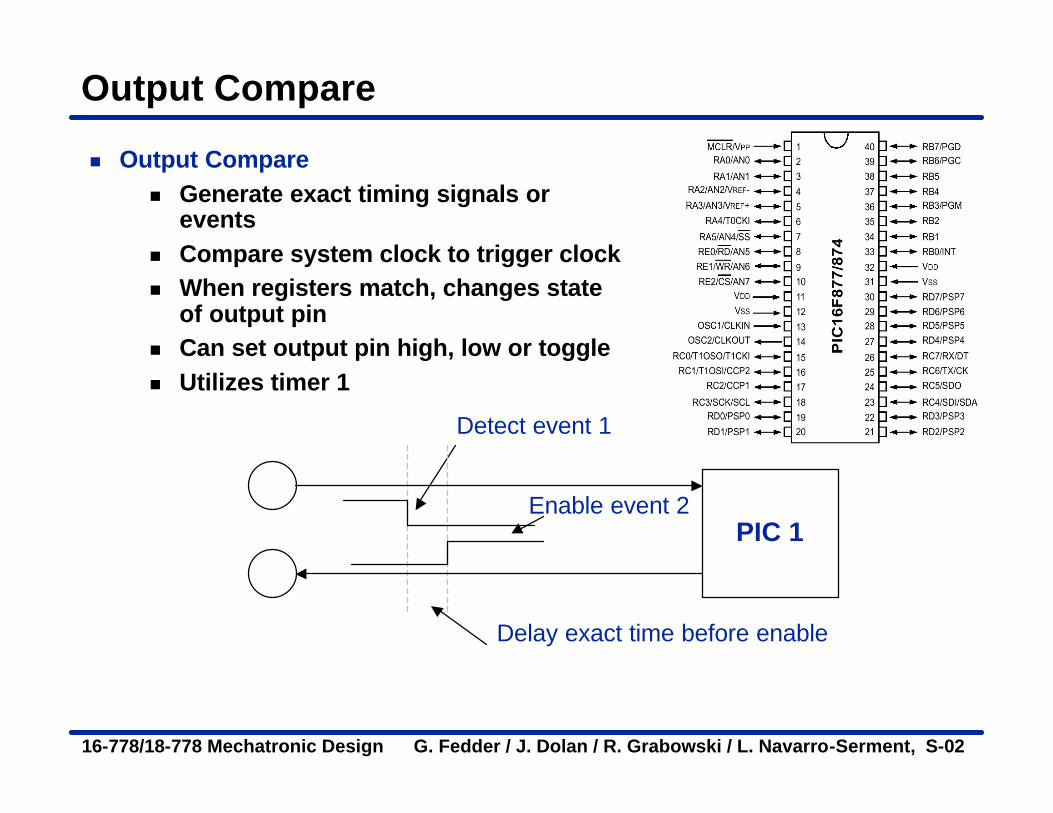
Output Compare
n Output Comparen Generate exact timing signals or
eventsn Compare system clock to trigger clockn When registers match, changes state
of output pinn Can set output pin high, low or togglen Utilizes timer 1
PIC 1
Detect event 1
Enable event 2
Delay exact time before enable

16-778/18-778 Mechatronic Design G. Fedder / J. Dolan / R. Grabowski / L. Navarro-Serment, S-02
Using Output Compare
n In Compare mode, the 16-bit CCPR1 register value is constantly compared against the TMR1 register pair value. When a match occurs, the RC2/CCP1 pin isn Driven highn Driven lown Remains unchanged
n Use this if you want to output precisely timed digital waveforms (timing, etc.)
n CCP_COMPARE_SET_ON_MATCHn CCP_COMPARE_CLR_ON_MATCHn CCP_COMPARE_INTn CCP_COMPARE_RESET_TIMER
16-778/18-778 Mechatronic Design G. Fedder / J. Dolan / R. Grabowski / L. Navarro-Serment, S-02
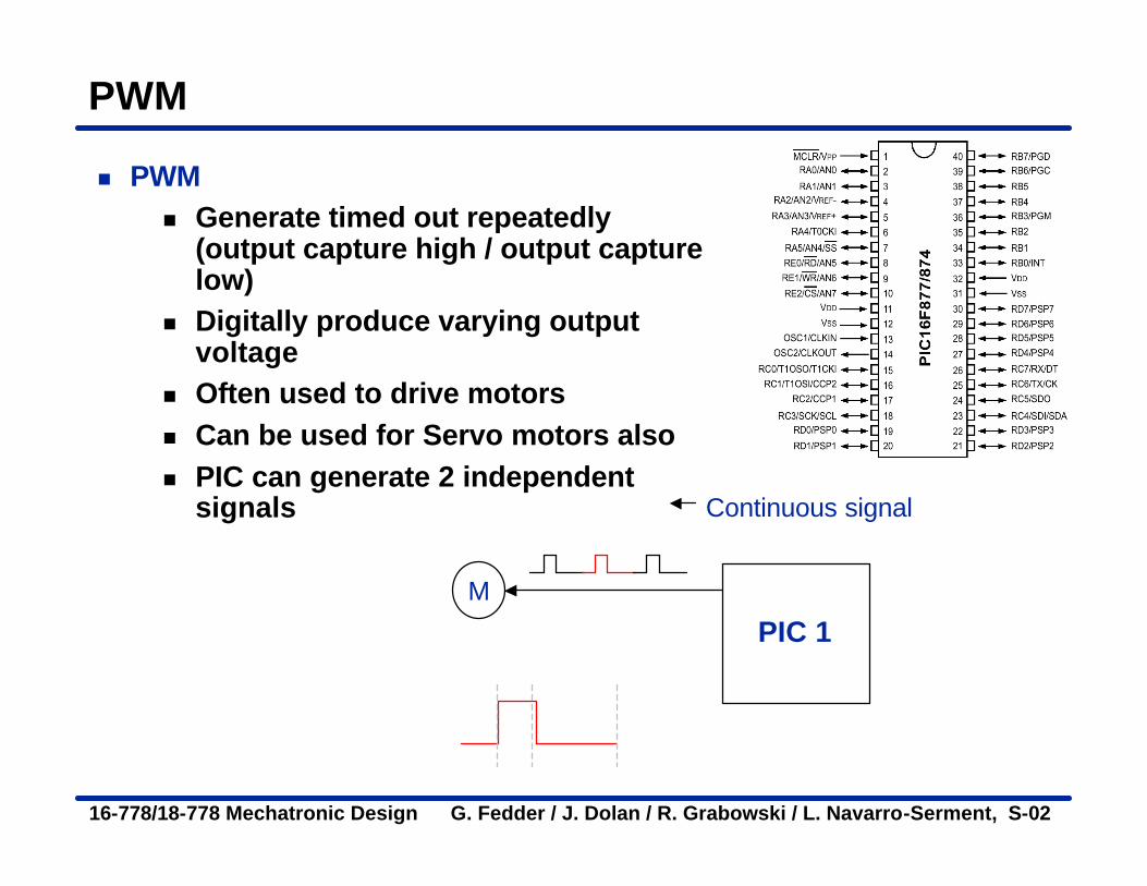
PWM
n PWMn Generate timed out repeatedly
(output capture high / output capture low)
n Digitally produce varying output voltage
n Often used to drive motorsn Can be used for Servo motors alson PIC can generate 2 independent
signals
PIC 1
Continuous signal
M
16-778/18-778 Mechatronic Design G. Fedder / J. Dolan / R. Grabowski / L. Navarro-Serment, S-02
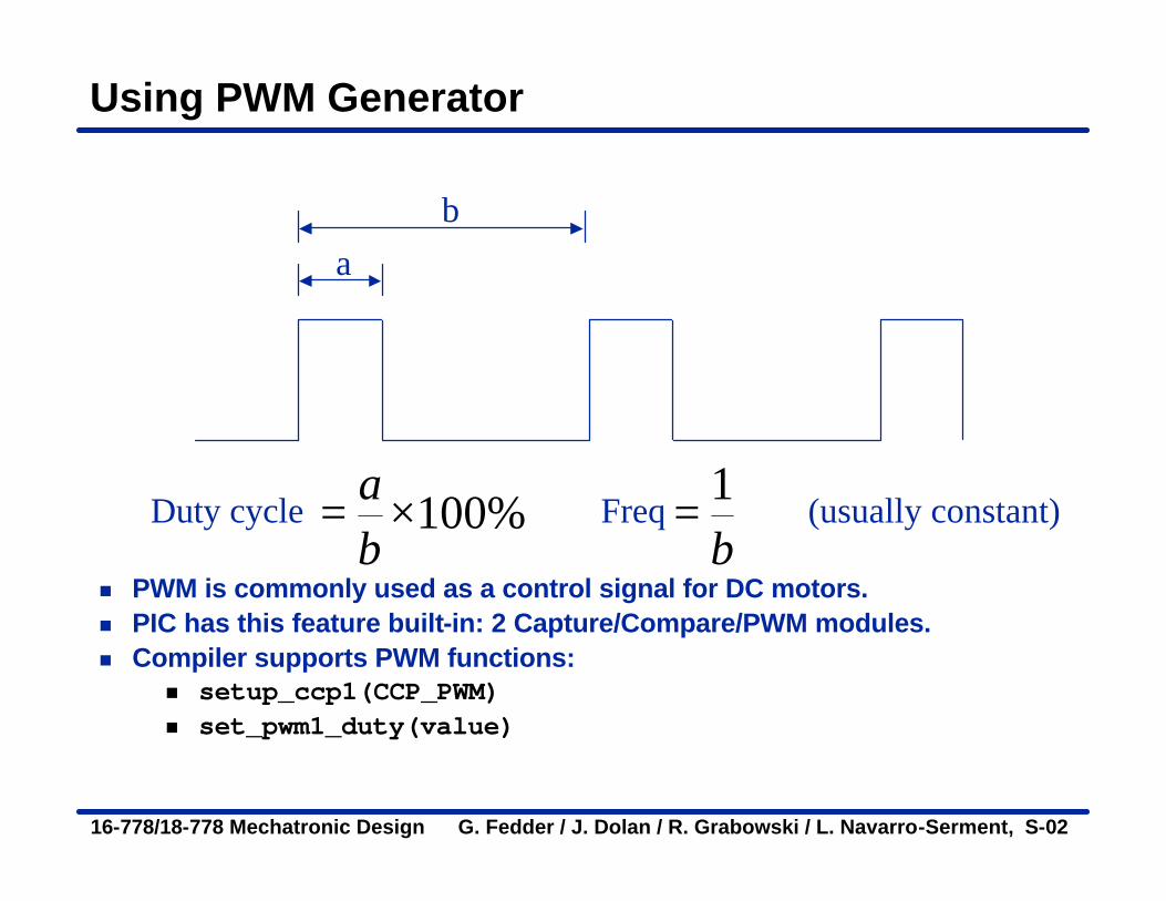
Using PWM Generator
n PWM is commonly used as a control signal for DC motors. n PIC has this feature built-in: 2 Capture/Compare/PWM modules.n Compiler supports PWM functions:
n setup_ccp1(CCP_PWM)n set_pwm1_duty(value)
ab
Duty cycle Freq (usually constant)100%ab
= ×1b
=
16-778/18-778 Mechatronic Design G. Fedder / J. Dolan / R. Grabowski / L. Navarro-Serment, S-02
PWM Generator (cont.)
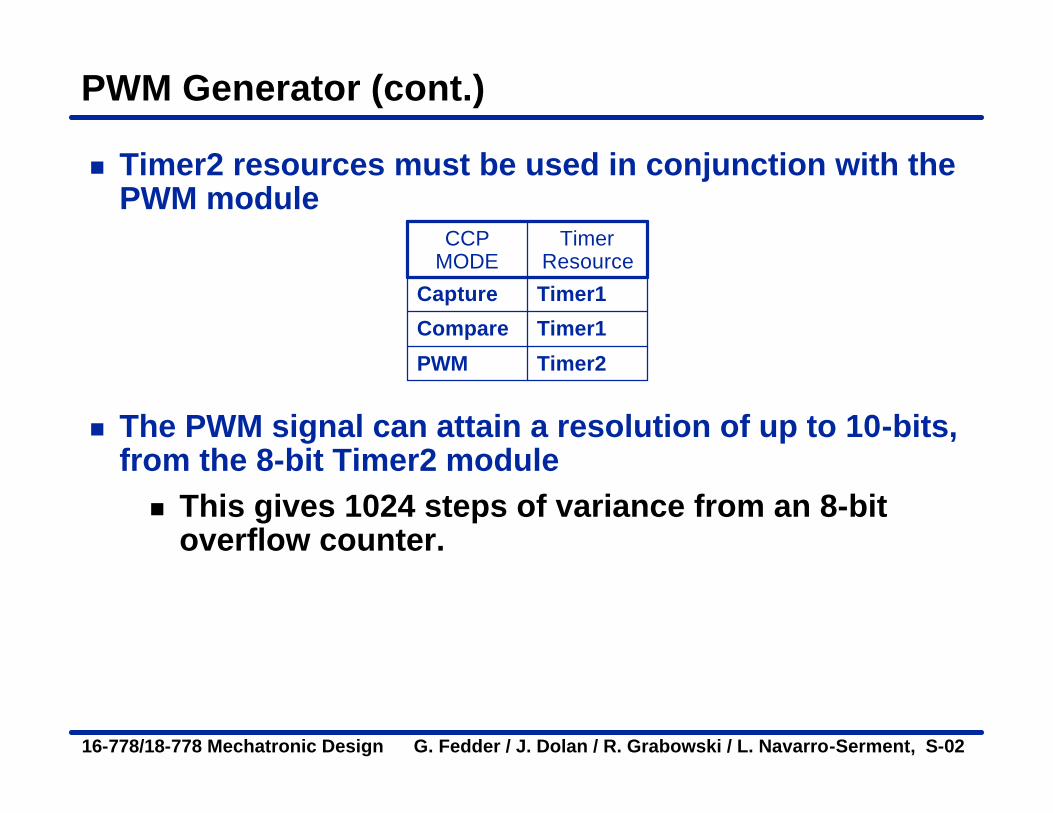
n Timer2 resources must be used in conjunction with the PWM module
n The PWM signal can attain a resolution of up to 10-bits, from the 8-bit Timer2 modulen This gives 1024 steps of variance from an 8-bit
overflow counter.
Timer2PWM
Timer1Compare
Timer1Capture
Timer Resource
CCP MODE
16-778/18-778 Mechatronic Design G. Fedder / J. Dolan / R. Grabowski / L. Navarro-Serment, S-02
PWM Generator (cont.)
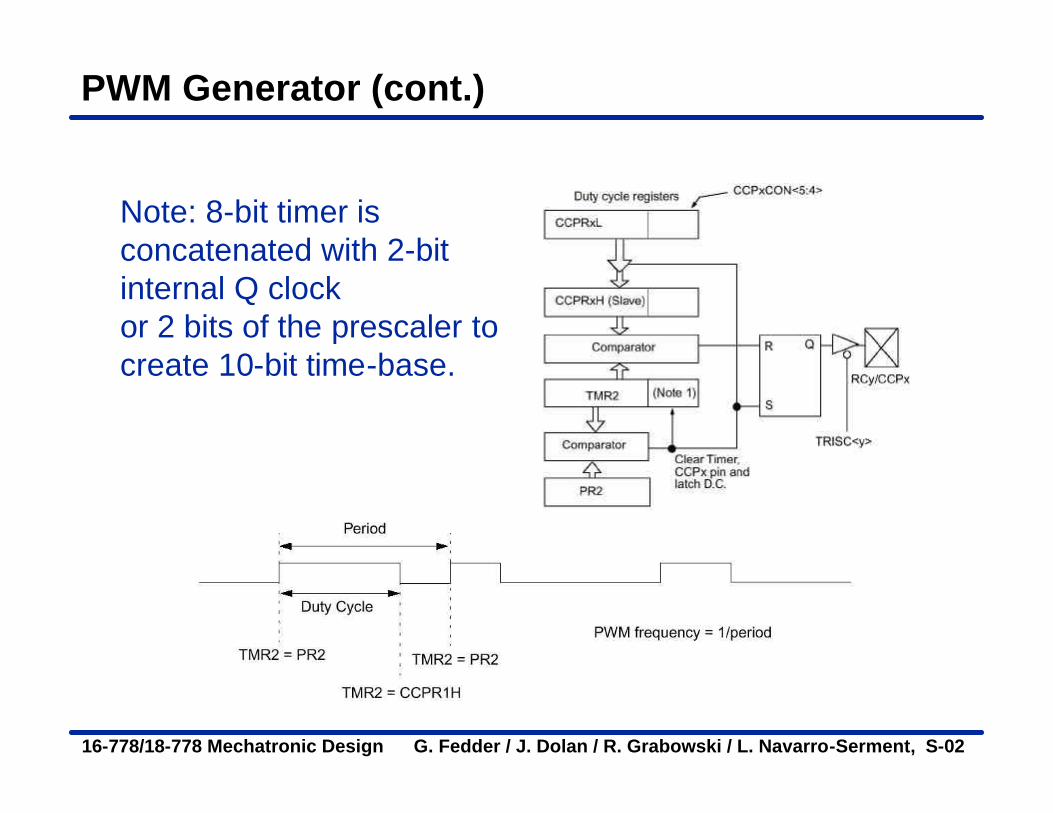
Note: 8-bit timer is concatenated with 2-bit internal Q clockor 2 bits of the prescaler to create 10-bit time-base.
16-778/18-778 Mechatronic Design G. Fedder / J. Dolan / R. Grabowski / L. Navarro-Serment, S-02
PWM
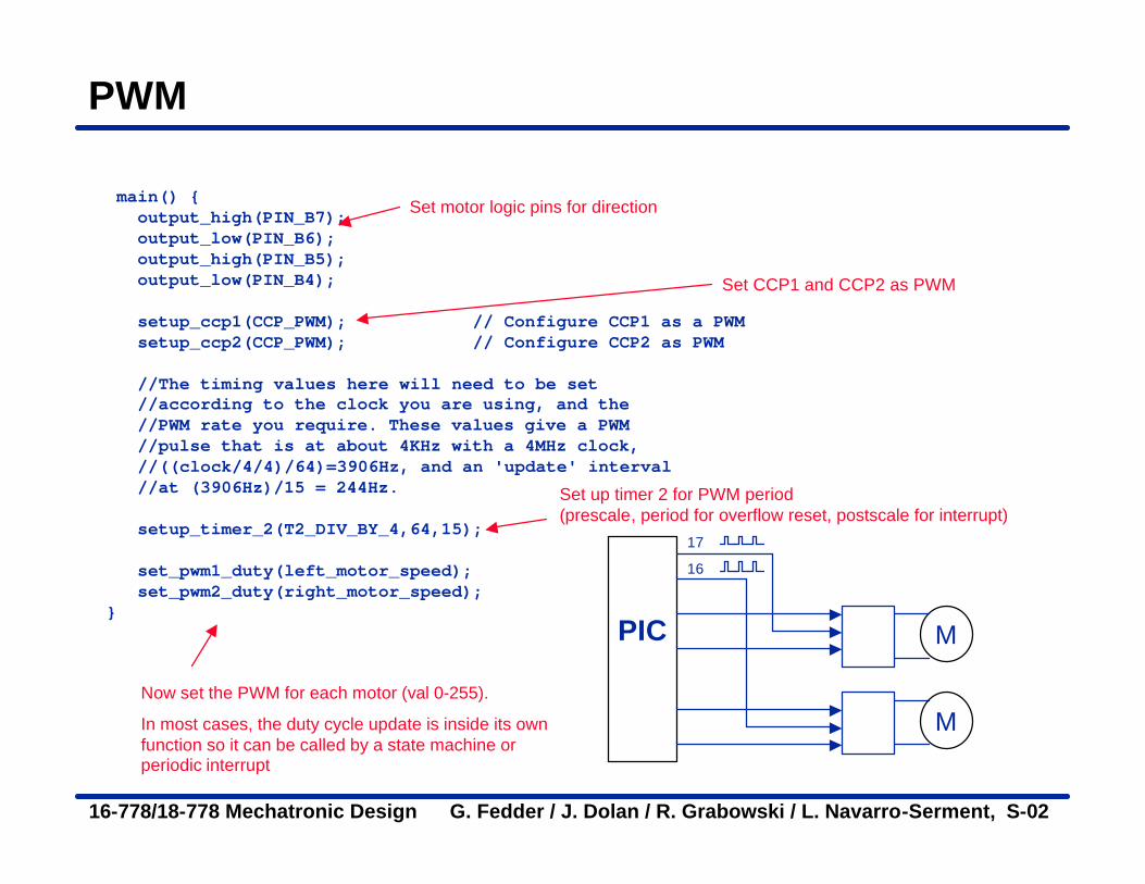
main() {output_high(PIN_B7);output_low(PIN_B6);output_high(PIN_B5);output_low(PIN_B4);
setup_ccp1(CCP_PWM); // Configure CCP1 as a PWMsetup_ccp2(CCP_PWM); // Configure CCP2 as PWM
//The timing values here will need to be set //according to the clock you are using, and the //PWM rate you require. These values give a PWM //pulse that is at about 4KHz with a 4MHz clock, //((clock/4/4)/64)=3906Hz, and an 'update' interval //at (3906Hz)/15 = 244Hz.
setup_timer_2(T2_DIV_BY_4,64,15);
set_pwm1_duty(left_motor_speed);set_pwm2_duty(right_motor_speed);
}PIC M
17
16
M
Set CCP1 and CCP2 as PWM
Set up timer 2 for PWM period (prescale, period for overflow reset, postscale for interrupt)
Now set the PWM for each motor (val 0-255).
In most cases, the duty cycle update is inside its own function so it can be called by a state machine or periodic interrupt
Set motor logic pins for direction
16-778/18-778 Mechatronic Design G. Fedder / J. Dolan / R. Grabowski / L. Navarro-Serment, S-02
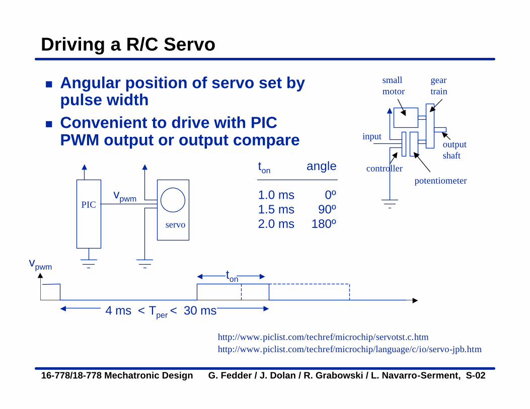
Driving a R/C Servo
n Angular position of servo set by pulse width
n Convenient to drive with PIC PWM output or output compare
http://www.piclist.com/techref/microchip/language/c/io/servo-jpb.htm
PIC
servo
http://www.piclist.com/techref/microchip/servotst.c.htm
ton
ton angle
1.0 ms 0º1.5 ms 90º2.0 ms 180º
4 ms < Tper < 30 ms
smallmotor
gear train
potentiometer
output shaft
controller
input
vpwm
vpwm
16-778/18-778 Mechatronic Design G. Fedder / J. Dolan / R. Grabowski / L. Navarro-Serment, S-02
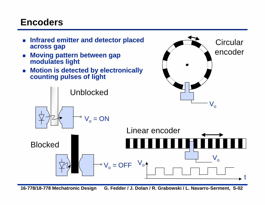
Encoders
n Infrared emitter and detector placed across gap
n Moving pattern between gap modulates light
n Motion is detected by electronically counting pulses of light
Vo
Circularencoder
Linear encoder
Vo = ON
Vo = OFF
Unblocked
Blocked
Vo
Vo
t
16-778/18-778 Mechatronic Design G. Fedder / J. Dolan / R. Grabowski / L. Navarro-Serment, S-02
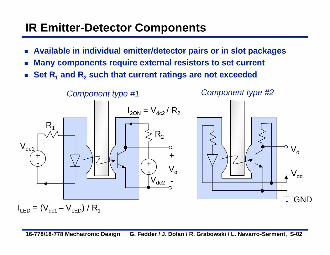
IR Emitter-Detector Components
n Available in individual emitter/detector pairs or in slot packagesn Many components require external resistors to set currentn Set R1 and R2 such that current ratings are not exceeded
Vo
+-
Vdc1
R1
ILED = (Vdc1 – VLED) / R1
+-Vdc2
I2ON = Vdc2 / R2
R2
+
-
Component type #1
Vo
Vdd
GND
Component type #2

16-778/18-778 Mechatronic Design G. Fedder / J. Dolan / R. Grabowski / L. Navarro-Serment, S-02
Circular Encoder Operation
n Three channels: Index, A and B
Index
Channel A
Channel B
n Dark is logic high (circuit dependent)
n Frequency gives speed
16-778/18-778 Mechatronic Design G. Fedder / J. Dolan / R. Grabowski / L. Navarro-Serment, S-02
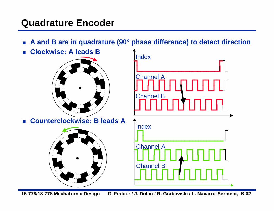
Quadrature Encoder
n A and B are in quadrature (90° phase difference) to detect directionn Clockwise: A leads B
Index
Channel A
Channel B
Index
Channel A
Channel B
n Counterclockwise: B leads A

16-778/18-778 Mechatronic Design G. Fedder / J. Dolan / R. Grabowski / L. Navarro-Serment, S-02
Measuring Shaft Speed
Method # 1n Use timer in counting moden Count the number of encoder pulses during a fixed time intervaln Number of counted pulses is directly proportional
to rotational speedn Resolution = 1 / ( tcount • N • vm )
Time
tcount
Encoder output
60 pm
count
nv
N t⋅
=⋅
N = encoder counts per rev.np = number of pulses countedvm = motor speed in rpmtcount = duration of counting interval
Count pulses
np = 3

16-778/18-778 Mechatronic Design G. Fedder / J. Dolan / R. Grabowski / L. Navarro-Serment, S-02
Counting with Interrupts
n Encoder signal can be fastn For example…
n HP HEDS-9X00 encoder has up to 512 counts/revolutionn At 10 rev/sec, output is 5120 counts/sec = 5120 Hzn If interrupts were used to count pulses, microcontroller
would be interrupted every 195 µs; no time for much else..n Use overflow interrupt; then 256 * 195 µs = 50 ms
n Consider counting in external hardwaren Can use divide by N digital countersn D flip-flop can be used for up/down count indicator
QDCLK
AB
CW/CCWUP/DOWN
CLK Q2Q4
Q8Q16
16-778/18-778 Mechatronic Design G. Fedder / J. Dolan / R. Grabowski / L. Navarro-Serment, S-02
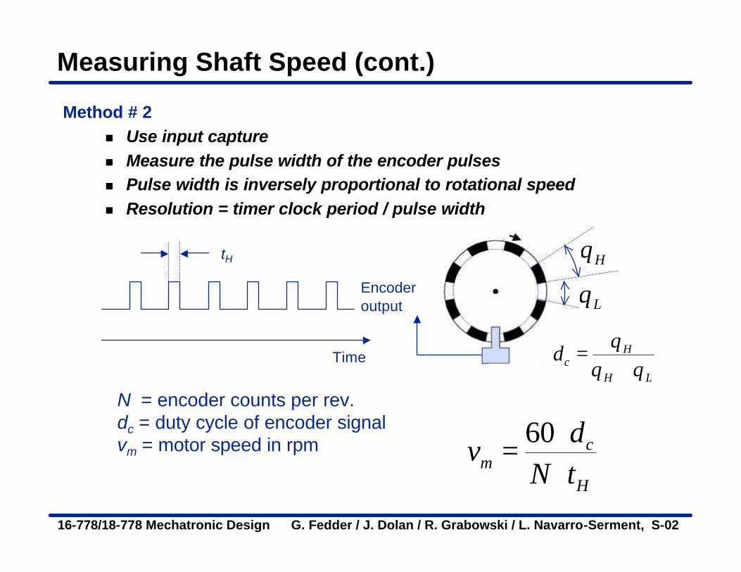
Measuring Shaft Speed (cont.)
Method # 2n Use input capturen Measure the pulse width of the encoder pulsesn Pulse width is inversely proportional to rotational speedn Resolution = timer clock period / pulse width
Time
Encoder output
tH
N = encoder counts per rev.dc = duty cycle of encoder signalvm = motor speed in rpm 60 c
mH
dv
N t⋅
=⋅
Hθ
Lθ
Hc
H L
dθ
θ θ=
+
16-778/18-778 Mechatronic Design G. Fedder / J. Dolan / R. Grabowski / L. Navarro-Serment, S-02
Pulse Width Measurement Limitations
n For example…n HP HEDS-9X00 encoder has up to 512
counts/revolutionn At 10 rev/sec, output is 5120 counts/sec = 5120 Hzn Pulse width = 98 µs n Fastest timer clock = 1 µs (with 4 MHz crystal)n Resolution = 1/98 = 1 % accuracy
n Turn on interrupts at some extended intervaln Otherwise no time to do anything else..
16-778/18-778 Mechatronic Design G. Fedder / J. Dolan / R. Grabowski / L. Navarro-Serment, S-02
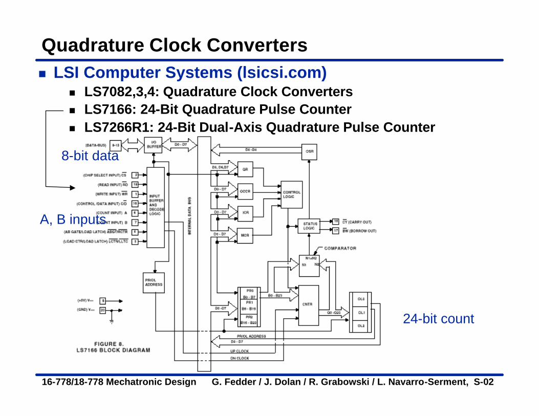
Quadrature Clock Convertersn LSI Computer Systems (lsicsi.com)
n LS7082,3,4: Quadrature Clock Convertersn LS7166: 24-Bit Quadrature Pulse Countern LS7266R1: 24-Bit Dual-Axis Quadrature Pulse Counter
24-bit count
A, B inputs
8-bit data