PIC-Gen Frequency Generator/Counter - n5dux.comn5dux.com/ham/files/pdf/PIC-Gen Frequency...
7
JOHN BECKER . workshop faci/ie:ies, OMBLWG the sophis~icated features of a Maxirn MAX038 waveform generator and a PIC16F877 micro- controller has resulted in a highly versatile and inexpensive workshop tool whose facilities have hitherto been unattainable without considerable design complexity. The MAX038 is a high-frequency preci- sjon funct~ongenerator whose output is selectable to produce triangle, sine and square waveforms, within a wide operating frequency span of O.1Hz to over IOMHz, split in the PIC-Gen as eight overlapping frequency ranges. Range and waveform selection are performed by the PIC1 6F877 in response to pushbutton switch controls. Frequency is fully variable within the seiecxed range by means of a front panel control potentiometer. An alphanumeric liquid crystal module displays the frequency and range information. Four frequency outpttts are provided: O Direct output at k1V peak-to-peak @ A.C. coupled output, fully variable between zero and 4V peak-to-peak @B Puise output, OV to 5V logic level @ 3.2768MKz fixed frequency, OV to 5V Iogic level The PIC is also used as a frequency ;ounter, switch selectable to monitor the kequency generated by the MAX038, or iom an external source in conjuncrion with i pre-conditioning waveform shaper and 'requency divider. Two external signal npnts are provided: one for OV to 5V Iogic eve1 waveforms, the other for a.c. waT/e- o m s having a peak-to-peak swing of letween a,bout 2V to 5V. The prototype can nonitor frequencies in excess s f 4OMHz. same name. He followed it up with a full constructional article, the IOMHz firzction Generator, in October '96. Prior to the introduction of the MAX038, arguably the main contender for the most widely used function generator was the 8038, manufactured by various companies under different prefix codings, such as ICL8038 and XR.8038, for instance. The 8038 is still widely used but it has limitations in the maximum frequency that can be generated. The range is typically 0.001Hz to ZOOlE-Iz. The MAX038, however, is stated to have an upper frequency limit of at least 20MMz, and possibly around 40MHz. It has to be said, though, that attaining such high fre- quencies requires printed circuit board design and construction techniques normal- ly found only in commercial manufacturing establishments. The upper frequency limit of the device is dependent not only on very accurate control of the current flowing into its fre- quency setting inputs, but also on the capacitance associated with them. Maxim state in their data sheet, for instance, that the specified upper frequency limit is achieved when the timing capacitance is less than or equal to 15pF and the control culrent is 500pA. Unfortunately, on a p.c.b. designed for successfui assembiy by the average hobby- ist, the capacitance between the MAX038, other components and the tracks is likely to prevent the maxirnum frequency from being reached. The prototype PIC-Gen described here achieves a maximum of just over lOMII2. PIC-GEM CDMGEPP Considering how the MAX038 might be put under serd-automatic control as part of a frequency generator and counter system, the author recognised t h a ~ a PIC16F877 microcontroiler nrigfit provide the key. This device has five input-output pons which, it seemed, could possibly provide automated switching of the frequency range capaci- tors, seiection of the waveform shape, offer frequency counting and provide an output to a liquid crystal display. Doing a basic mock-up on stripboard coupled to a PIC roug'hiy p r o g r m e d to perform t'le bare essentials proved the via- bility of the idea. The concept was then given h l l flesh and bones to become the design whose circuit diagram is given in Fig.1. The M4XO38 function generator is shown as iC2. Lt will be seen that half the pins are gounded and from some of tffeir notations it will probably be icol~ectly) deduced that the device has more functions than are used here. For information about the device's full range of functions, see its In EPE Septembe: '96, Andy Flind first ~troduced readers to the merits of the then ewly introduced MAX038 waveform enerator, in a special feature article nf the
Transcript of PIC-Gen Frequency Generator/Counter - n5dux.comn5dux.com/ham/files/pdf/PIC-Gen Frequency...
JOHN BECKER .
workshop faci/ie:ies, OMBLWG the sophis~icated features of a Maxirn MAX038 waveform generator and a PIC16F877 micro-
controller has resulted in a highly versatile and inexpensive workshop tool whose facilities have hitherto been unattainable without considerable design complexity.
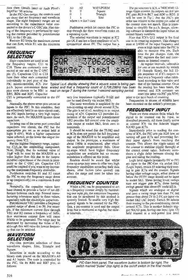
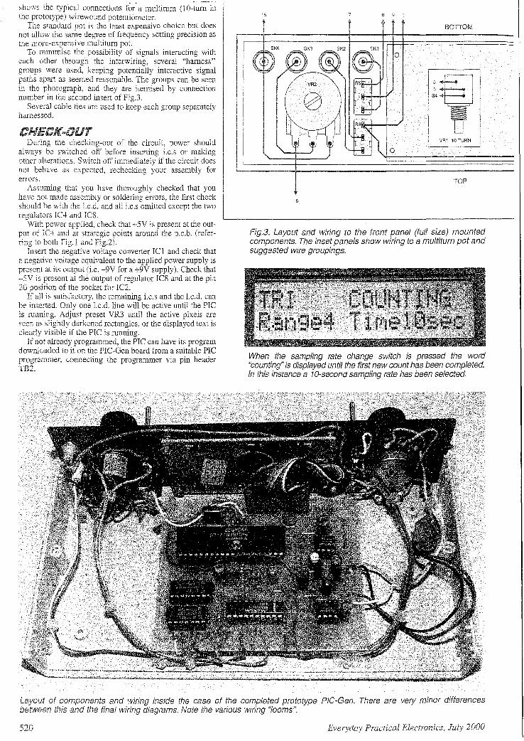
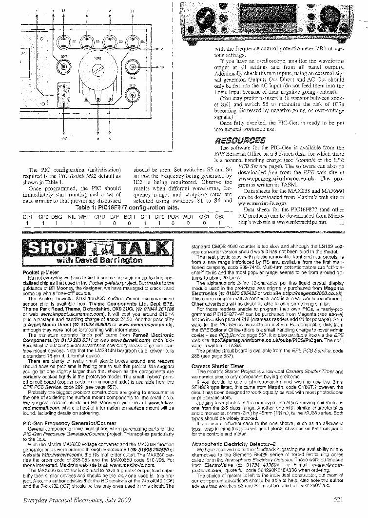
The MAX038 is a high-frequency preci- sjon funct~on generator whose output is selectable to produce triangle, sine and square waveforms, within a wide operating frequency span of O.1Hz to over IOMHz, split in the PIC-Gen as eight overlapping frequency ranges. Range and waveform selection are performed by the PIC1 6F877 in response to pushbutton switch controls. Frequency is fully variable within the seiecxed range by means of a front panel control potentiometer. An alphanumeric liquid crystal module
displays the frequency and range information. Four frequency outpttts are provided:
O Direct output at k1V peak-to-peak
@ A.C. coupled output, fully variable between zero and 4V peak-to-peak
@B Puise output, OV to 5V logic level
@ 3.2768MKz fixed frequency, OV to 5V Iogic level
The PIC is also used as a frequency ;ounter, switch selectable to monitor the kequency generated by the MAX038, or iom an external source in conjuncrion with i pre-conditioning waveform shaper and 'requency divider. Two external signal npnts are provided: one for OV to 5V Iogic eve1 waveforms, the other for a.c. waT/e- o m s having a peak-to-peak swing of letween a,bout 2V to 5V. The prototype can nonitor frequencies in excess s f 4OMHz.
same name. He followed it up with a full constructional article, the IOMHz firzction Generator, in October '96.
Prior to the introduction of the MAX038, arguably the main contender for the most widely used function generator was the 8038, manufactured by various companies under different prefix codings, such as ICL8038 and XR.8038, for instance.
The 8038 is still widely used but it has limitations in the maximum frequency that can be generated. The range is typically 0.001Hz to ZOOlE-Iz.
The MAX038, however, is stated to have an upper frequency limit of at least 20MMz, and possibly around 40MHz. It has to be said, though, that attaining such high fre- quencies requires printed circuit board design and construction techniques normal- ly found only in commercial manufacturing establishments.
The upper frequency limit of the device is dependent not only on very accurate control of the current flowing into its fre- quency setting inputs, but also on the capacitance associated with them. Maxim state in their data sheet, for instance, that the specified upper frequency limit is achieved when the timing capacitance is less than or equal to 15pF and the control culrent is 500pA.
Unfortunately, on a p.c.b. designed for successfui assembiy by the average hobby- ist, the capacitance between the MAX038, other components and the tracks is likely to prevent the maxirnum frequency from being reached. The prototype PIC-Gen described here achieves a maximum of just over lOMII2.
PIC-GEM CDMGEPP Considering how the MAX038 might be
put under serd-automatic control as part of a frequency generator and counter system, the author recognised t h a ~ a PIC16F877 microcontroiler nrigfit provide the key. This device has five input-output pons which, it seemed, could possibly provide automated switching of the frequency range capaci- tors, seiection of the waveform shape, offer frequency counting and provide an output to a liquid crystal display.
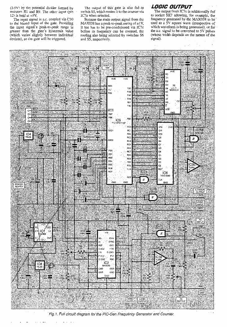
Doing a basic mock-up on stripboard coupled to a PIC roug'hiy p r o g r m e d to perform t'le bare essentials proved the via- bility of the idea. The concept was then given h l l flesh and bones to become the design whose circuit diagram is given in Fig.1.
The M4XO38 function generator is shown as iC2. Lt will be seen that half the pins are gounded and from some of tffeir notations it will probably be icol~ectly) deduced that the device has more functions than are used here. For information about the device's full range of functions, see its
In EPE Septembe: '96, Andy Flind first ~troduced readers to the merits of the then ewly introduced MAX038 waveform enerator, in a special feature article nf the