PIC Dev 14 Surface Mount PCB Assembly and...
5
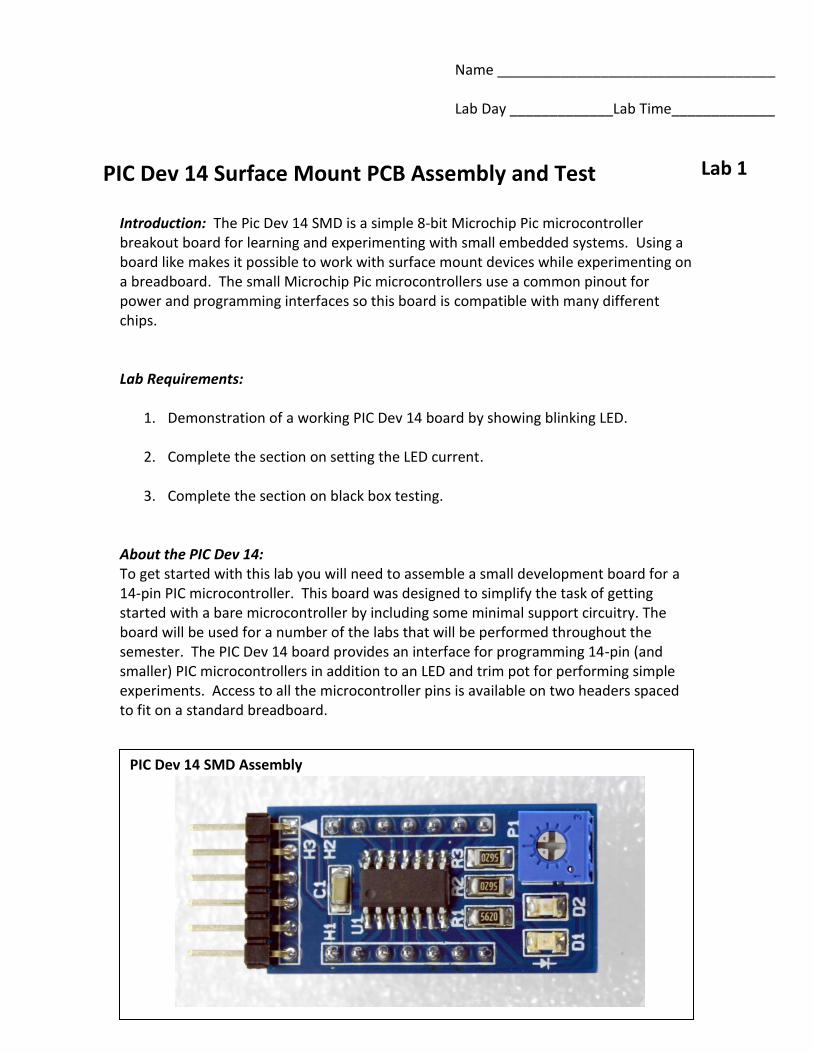
Name ___________________________________ Lab Day _____________Lab Time_____________ PIC Dev 14 Surface Mount PCB Assembly and Test Lab 1 Introduction: The Pic Dev 14 SMD is a simple 8-bit Microchip Pic microcontroller breakout board for learning and experimenting with small embedded systems. Using a board like makes it possible to work with surface mount devices while experimenting on a breadboard. The small Microchip Pic microcontrollers use a common pinout for power and programming interfaces so this board is compatible with many different chips. Lab Requirements: 1. Demonstration of a working PIC Dev 14 board by showing blinking LED. 2. Complete the section on setting the LED current. 3. Complete the section on black box testing. About the PIC Dev 14: To get started with this lab you will need to assemble a small development board for a 14-pin PIC microcontroller. This board was designed to simplify the task of getting started with a bare microcontroller by including some minimal support circuitry. The board will be used for a number of the labs that will be performed throughout the semester. The PIC Dev 14 board provides an interface for programming 14-pin (and smaller) PIC microcontrollers in addition to an LED and trim pot for performing simple experiments. Access to all the microcontroller pins is available on two headers spaced to fit on a standard breadboard. PIC Dev 14 SMD Assembly
Transcript of PIC Dev 14 Surface Mount PCB Assembly and...
Name ___________________________________
Lab Day _____________Lab Time_____________
PIC Dev 14 Surface Mount PCB Assembly and Test Lab 1
Introduction: The Pic Dev 14 SMD is a simple 8-bit Microchip Pic microcontroller breakout board for learning and experimenting with small embedded systems. Using a board like makes it possible to work with surface mount devices while experimenting on a breadboard. The small Microchip Pic microcontrollers use a common pinout for power and programming interfaces so this board is compatible with many different chips. Lab Requirements:
1. Demonstration of a working PIC Dev 14 board by showing blinking LED.
2. Complete the section on setting the LED current.
3. Complete the section on black box testing.
About the PIC Dev 14: To get started with this lab you will need to assemble a small development board for a 14-pin PIC microcontroller. This board was designed to simplify the task of getting started with a bare microcontroller by including some minimal support circuitry. The board will be used for a number of the labs that will be performed throughout the semester. The PIC Dev 14 board provides an interface for programming 14-pin (and smaller) PIC microcontrollers in addition to an LED and trim pot for performing simple experiments. Access to all the microcontroller pins is available on two headers spaced to fit on a standard breadboard.
PIC Dev 14 SMD Assembly
Connecting the Programmer:
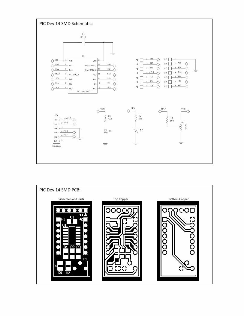
PIC Dev 14 SMD Schematic:
PIC Dev 14 SMD PCB: Silkscreen and Pads Top Copper Bottom Copper
Setting the LED Current: While developing firmware, it is often useful to have an LED blinking at a periodic rate to show that your system is powered up and running (heartbeat indicator). The schematic shows a 560Ω Resistor in series with the LED to set the maximum current through the LED. This value was chosen to set the brightness for a specific type of LED (color, size and efficiency). The LED that you select for your board will most likely be different and require a different resistor value to get a desirable intensity.
Current through the LED: for example
Most digital multimeter’s (DMM) have a “DIODE” mode that is useful for measuring the forward voltage of a semiconductor junction at a given current. The test current is typically between 100µA and 1mA which is low enough to prevent damage to the device but high enough to get an estimate of the forward voltage. This estimate will be good enough for today’s calculations. Select an LED and measure the forward voltage using the DMM:
Describe your LED (shape, color, size) _________________________________________
Measured Vf ____________ How can you tell the anode from the cathode? _________________________________
Calculate the resistor needed for the following LED currents assuming VDD = 5V
ILED 1mA R1 = _________ ILED5mA R1 = _________ ILED10mA R1 = _________ Test your LED with the approximate values above and select a resistor that gives a luminous intensity that you are happy with. Value selected for R1 __________ Construction: Review the schematic and printed circuit board layout then collect all the parts needed to assemble the PCB. Be careful to install the LED and microcontroller in the correct orientation. The polarity of the surface mount LED is indicated on the back side of the part and on the PCB silkscreen. Pin 1 of the PIC microcontroller faces towards the ICD programming header and is indicated on the silkscreen. A video showing how to build the board is available on the class webpage.
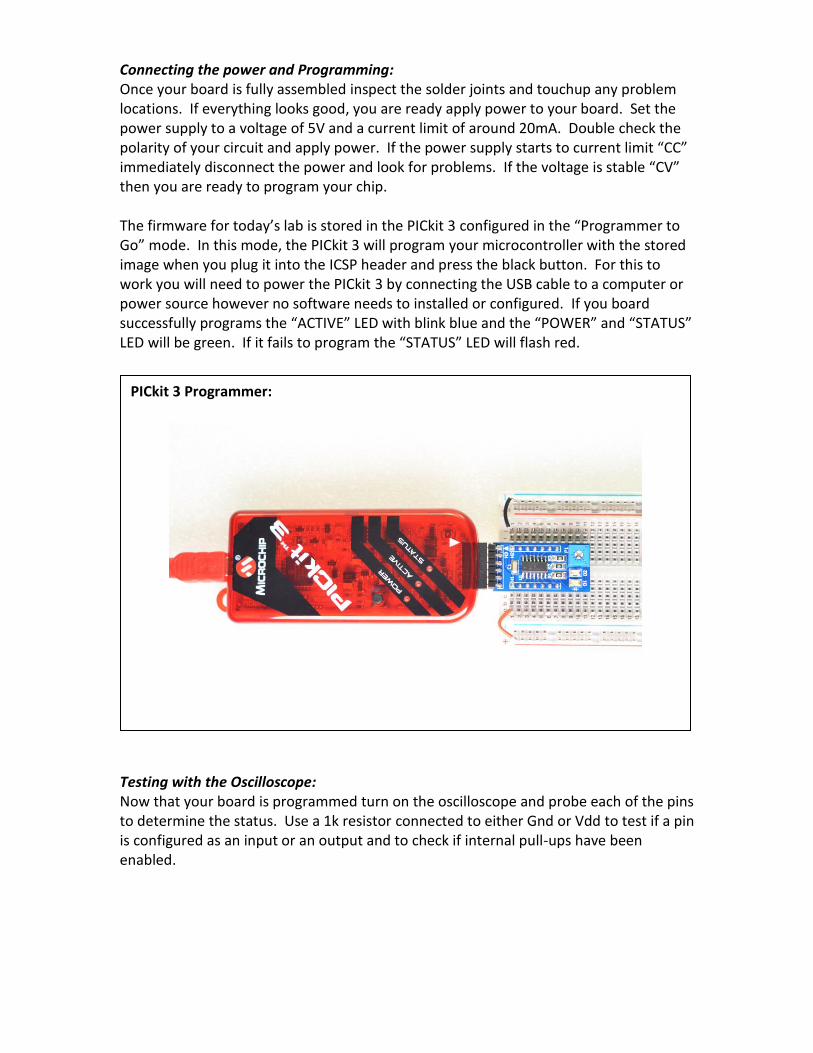
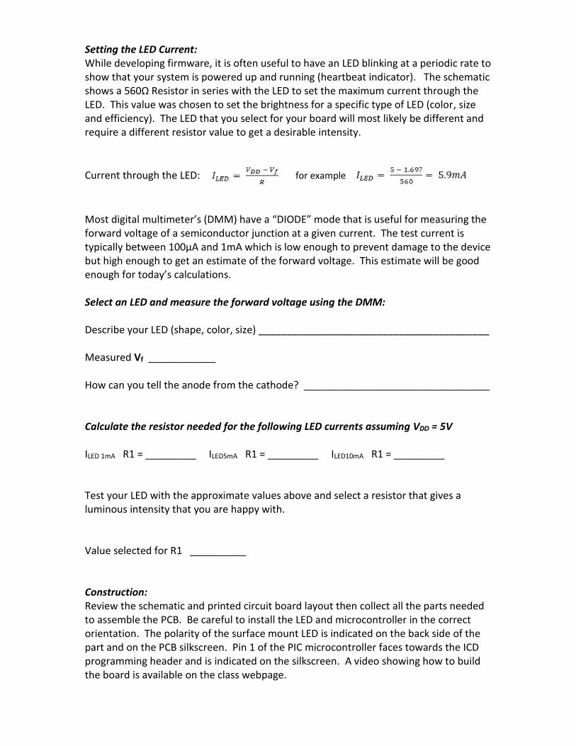
Connecting the power and Programming: Once your board is fully assembled inspect the solder joints and touchup any problem locations. If everything looks good, you are ready apply power to your board. Set the power supply to a voltage of 5V and a current limit of around 20mA. Double check the polarity of your circuit and apply power. If the power supply starts to current limit “CC” immediately disconnect the power and look for problems. If the voltage is stable “CV” then you are ready to program your chip. The firmware for today’s lab is stored in the PICkit 3 configured in the “Programmer to Go” mode. In this mode, the PICkit 3 will program your microcontroller with the stored image when you plug it into the ICSP header and press the black button. For this to work you will need to power the PICkit 3 by connecting the USB cable to a computer or power source however no software needs to installed or configured. If you board successfully programs the “ACTIVE” LED with blink blue and the “POWER” and “STATUS” LED will be green. If it fails to program the “STATUS” LED will flash red.
Testing with the Oscilloscope: Now that your board is programmed turn on the oscilloscope and probe each of the pins to determine the status. Use a 1k resistor connected to either Gnd or Vdd to test if a pin is configured as an input or an output and to check if internal pull-ups have been enabled.
PICkit 3 Programmer: