PI5USB30216D USB Type-C Plug Orientation (CC Pins ... · USB Type-C Plug Orientation (CC Pins)...
15
Pericom Semiconductor Corp. www.pericom.com Page 1 of 15 6/19/2017 AN AN PI5USB30216D USB Type-C Plug Orientation (CC Pins) Detector Version 1.1 Table of Contents 1 Introduction ................................................................................................................................................................ 2 2 Settings of PI5USB30216D ............................................................................................................................................ 2 2.1 Port Role Setting via Pin Control Mode ...................................................................................................................... 2 2.2 Port Role Setting via I2C Control Mode ...................................................................................................................... 3 3 Processor Communication via I2C Control Mode ........................................................................................................... 3 3.1 I2C Configuration Sequence ...................................................................................................................................... 5 3.2 Power-up Sequence in I2C Control Mode. .................................................................................................................. 6 3.3 Power-down and Power-up through EN pin ............................................................................................................... 6 3.4 Power-down and Power-up via Powersaving bit in I2C Control Mode ......................................................................... 6 3.5 I2C Register Quick Reference Table ........................................................................................................................... 7 4 Typical Application Circuit ............................................................................................................................................ 9 4.1 DRP in I2C Mode....................................................................................................................................................... 9 4.2 UFP Mode .............................................................................................................................................................. 10 4.2.1 UFP in I2C Mode ................................................................................................................................................. 10 4.2.2 UFP in Pin Mode ................................................................................................................................................. 11 5 Layout Recommendation ........................................................................................................................................... 12 5.1 Layout Recommendation ........................................................................................................................................ 12 5.2 Layout Example ...................................................................................................................................................... 13 6. Software Example ...................................................................................................................................................... 14
Transcript of PI5USB30216D USB Type-C Plug Orientation (CC Pins ... · USB Type-C Plug Orientation (CC Pins)...

Pericom Semiconductor Corp.
www.pericom.com
Page 1 of 15 6/19/2017
AN
AN
PI5USB30216D USB Type-C Plug Orientation (CC Pins) Detector
Version 1.1 Table of Contents
1 Introduction ................................................................................................................................................................ 2
2 Settings of PI5USB30216D ............................................................................................................................................ 2
2.1 Port Role Setting via Pin Control Mode ...................................................................................................................... 2
2.2 Port Role Setting via I2C Control Mode ...................................................................................................................... 3
3 Processor Communication via I2C Control Mode ........................................................................................................... 3
3.1 I2C Configuration Sequence ...................................................................................................................................... 5
3.2 Power-up Sequence in I2C Control Mode. .................................................................................................................. 6
3.3 Power-down and Power-up through EN pin ............................................................................................................... 6
3.4 Power-down and Power-up via Powersaving bit in I2C Control Mode ......................................................................... 6
3.5 I2C Register Quick Reference Table ........................................................................................................................... 7
4 Typical Application Circuit ............................................................................................................................................ 9
4.1 DRP in I2C Mode....................................................................................................................................................... 9
4.2 UFP Mode .............................................................................................................................................................. 10
4.2.1 UFP in I2C Mode ................................................................................................................................................. 10
4.2.2 UFP in Pin Mode ................................................................................................................................................. 11
5 Layout Recommendation ........................................................................................................................................... 12
5.1 Layout Recommendation ........................................................................................................................................ 12
5.2 Layout Example ...................................................................................................................................................... 13
6. Software Example ...................................................................................................................................................... 14

Pericom Semiconductor Corp.
www.pericom.com
Page 2 of 15 6/19/2017
AN
AN
1 Introduction Pericom's PI5USB30216D is a Type-C Configuration Channel (CC) logic IC. The device implements CC pins for port attachment, detachment, cable orientation, role detection, and Type-C Current Mode control. The device supports host only mode (Source/DFP), device only mode (Sink/UFP) and dual role port (DRP/Try.SNK DRP and Try.SRC DRP) modes with automatic configuration based on the voltage levels detected on CC pins. The device supports both pin and I2C control mode. I2C control mode allows higher flexibility of port control and communications. Packaging: 12-contact X2QFN (1.6mmx1.6mm)
2 Settings of PI5USB30216D The Type-C port role of PI5USB30216D can be controlled via two modes – pin control and I2C control. ADDR pin is used to select the desired mode. If ADDR pin is set to either high or low, I2C control is active. SDA/OUT1 and SCL/OUT2 are used for I2C transaction. ADDR is also to set the I2C address. If ADDR pin is floating, pin control mode is active.
ADDR pin I2C address format I2C address
ADDR=GND 7-bit addressing 0x1D 8-bit address Write:0x3A; Read:0x3B
ADDR=VDD 7-bit addressing 0x3D 8-bit address Write:0x7A; Read:0x7B
ADDR=FLOAT Pin control mode
Table 1: ADDR setting
2.1 Port Role Setting via Pin Control Mode Default current host/DFP only mode, device/UFP only mode and default current Try.SNK DRP mode are available. PORT pin is used to configure the role of Type-C Port in pin control mode and the settings can be referred to the table below.
Table 2: Port Setting

Pericom Semiconductor Corp.
www.pericom.com
Page 3 of 15 6/19/2017
AN
AN
2.2 Port Role Setting via I2C Control Mode The settings of port role are referred to byte2 of I2C Register Description on Pericom datasheet.
Table 3: Port Setting Register
3 Processor Communication via I2C Control Mode Please noted that PI5USB30216D does not have offset byte*. All registers must be read or written sequentially from 0x01. For example, in order to read address 0x04, PI5USB30216D I2C registers must be read sequentially from 0x01, 0x02, 0x03 to 0x04. In order to write address 0x02, it must be written sequentially from 0x01 to 0x02. *Please use “I2C Transport” API instead of “I2C SMBus” API to communicate with PI5USB30216D if needed. Processor should use following procedure to process PI5USB30216D interrupt request: 1. INTB asserted LOW, indicating Type-C port status change. 2. Processor first masks PI5USB30216D interrupt by writing a ‘1’ to Bit 0 of Control Register(0x02). INTB returned
Hi-Z. 3. Processor then read Register(0x01), Control Register (0x02), Interrupt Register(0x03) and CC Status
Register(0x04). Interrupt Register(0x03) indicates if an attach or detach event was detected. All interrupt flags in Interrupt Register will be cleared after the I2C read action. CC Status Register(0x04) is used to determine plugin details and charging profile. Processor can configure the power and USB channels according to information in CC Status Register.
Pericom Semiconductor Corp.
www.pericom.com
Page 4 of 15 6/19/2017
AN
AN
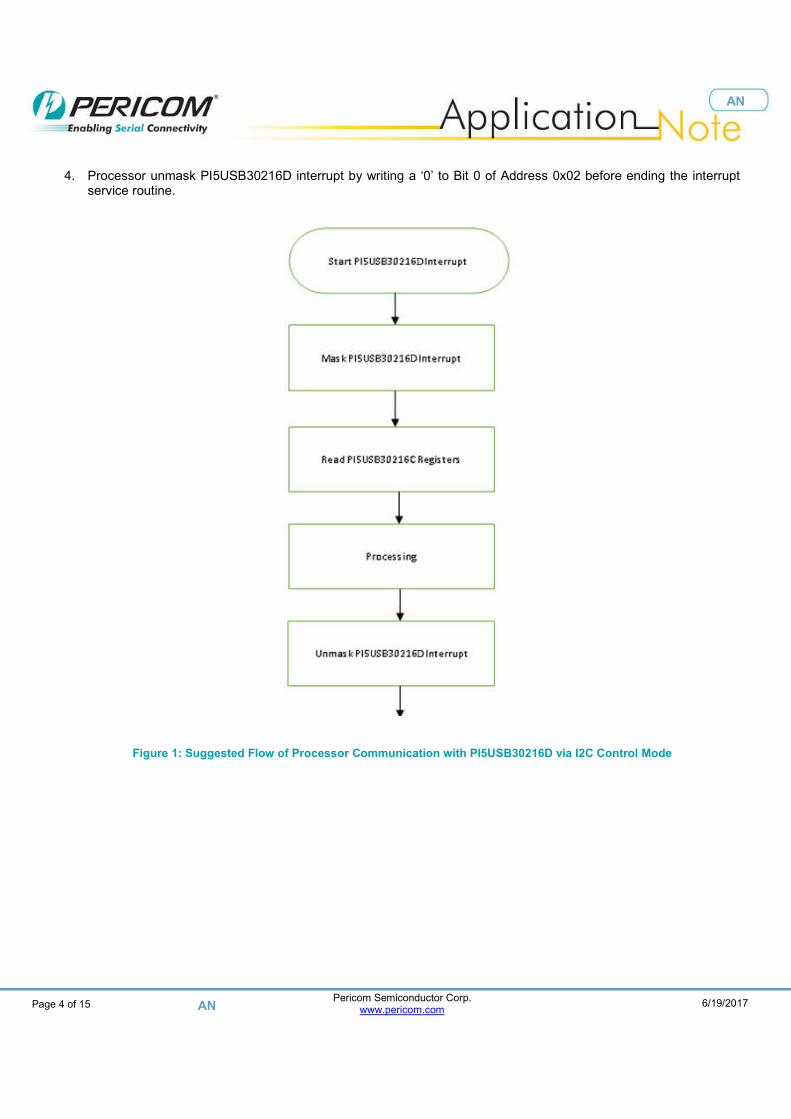
4. Processor unmask PI5USB30216D interrupt by writing a ‘0’ to Bit 0 of Address 0x02 before ending the interrupt service routine.
Figure 1: Suggested Flow of Processor Communication with PI5USB30216D via I2C Control Mode

Pericom Semiconductor Corp.
www.pericom.com
Page 5 of 15 6/19/2017
AN
AN
3.1 I2C Configuration Sequence
Figure 2: READ Sequence Diagram
Figure 4 below is one example for read sequence at ADDR=GND and Data Reg [1:4]=20,04,01,06.
Figure 3: I2C Read Sequence Sample
Figure 4: WRITE Sequence Diagram
Figure 6 below is one example for write sequence at ADDR=GND and Data Reg [1:2]=20,05.
Figure 5: I2C WRITE Sequence Sample

Pericom Semiconductor Corp.
www.pericom.com
Page 6 of 15 6/19/2017
AN
AN
3.2 Power-up Sequence in I2C Control Mode. The power-up sequence for the PI5USB30216D with EN tied to VDD is as follow: 1. When system is powered off and PI5USB30216D has no VDD, CC1 and CC2 are pulled low by
PI5USB30216D and the port acts as a UFP/Sink. 2. System powered on and supply VDD to PI5USB30216D. PI5USB30216D is reset by POR. 3. PI5USB30216D in I2C control mode is always initialized as UFP only mode (Reg[0x02]=00h) regardless of
PORT pin setting. 4. Write Reg[0x02]=81h 5. System can change PI5USB30216D to desired mode by writing byte2 according to “Port Setting Register” in
section 2.2. E.g. Write Reg[0x02]=46h to set the port to Try.SNK DRP default current mode.
6. PI5USB30216D monitors CC pins and VBUS for attachment and detachment.
3.3 Power-down and Power-up through EN pin The power-down sequence for the PI5USB30216D using EN is as follow: 1. Pull low EN to disable PI5USB30216D. PI5USB30216D will pull-low INTB. 2. PI5USB30216D I2C is still accessible and the system should read PI5USB30216D I2C as usual to clean the
interrupt. 3. The device is in disabled state and will pull low CC1 and CC2 and the port acts as a UFP/Sink. 4. User can re-enable the part by pull high EN pin.
3.4 Power-down and Power-up via Powersaving bit in I2C Control Mode
When EN is high, user can put PI5USB30216D into low power state via I2C as follow: 1. Write Reg[0x02]=81h to put the part in powersaving mode. 2. Read PI5USB30216D I2C to clear byte3 and byte4 3. The device will also pull low CC1 and CC2 and the port acts as a UFP/Sink. 4. User can re-enable the part by writing desired mode to byte2 according to “Port Setting Register” in section 2.2.
E.g. Write Reg[0x02]=46h to set the port to Try.SNK DRP default current mode.

Pericom Semiconductor Corp.
www.pericom.com
Page 7 of 15 6/19/2017
AN
AN
3.5 I2C Register Quick Reference Table Reg[0x02] PI5USB30216D Operating Mode CC1/2 voltage when
unattached ID pin
00h Sink/UFP; No accessory support GND “H”
01h Sink/UFP; No accessory support; Mask Interrupt 02h Source/DFP; Default USB Power
VDD
“L” when UFP is
attached
03h Source/DFP; Default USB Power; Mask Interrupt 04h DRP; Default USB Power Toggle between VDD and
GND 05h DRP; Default USB Power; Mask Interrupt 06h Try.SRC DRP; Default USB Power Toggle between VDD and
GND 07h Try.SRC DRP; Default USB Power; Mask Interrupt 0Ah Source/DFP; 1.5A Type-C Current Mode
VDD 0Bh Source/DFP; 1.5A Type-C Current Mode; Mask Interrupt 0Ch DRP; 1.5A Type-C Current Mode Toggle between VDD and
GND 0Dh DRP; 1.5A Type-C Current Mode; Mask Interrupt 0Eh Try.SRC DRP; 1.5A Type-C Current Mode Toggle between VDD and
GND 0Fh Try.SRC DRP; 1.5A Type-C Current Mode; Mask Interrupt 12h Source/DFP; 3A Type-C Current Mode
VDD 13h Source/DFP; 3A Type-C Current Mode; Mask Interrupt 14h DRP; 3A Type-C Current Mode Toggle between VDD and
GND 15h DRP; 3A Type-C Current Mode; Mask Interrupt 16h Try.SRC DRP; 3A Type-C Current Mode Toggle between VDD and
GND 17h Try.SRC DRP; 3A Type-C Current Mode; Mask Interrupt 46h Try.SNK DRP; Default USB Power Toggle between VDD and
GND 47h Try.SNK DRP; Default USB Power; Mask Interrupt 4Eh Try.SNK DRP; 1.5A Type-C Current Mode Toggle between VDD and
GND 4Fh Try.SNK DRP; 1.5A Type-C Current Mode; Mask Interrupt 56h Try.SNK DRP; 3A Type-C Current Mode Toggle between VDD and
GND 57h Try.SNK DRP; 3A Type-C Current Mode; Mask Interrupt 20h Sink/UFP; Support accessory Toggle between VDD and
GND “H”
21h Sink/UFP; Support accessory; Mask Interrupt Table 4: Control Register (Reg[0x02]) Quick Reference Table
Reg[0x03] PI5USB30216D Attach/Detach Event 00h No attach or detect event occurred since last I2C read. 01h Attach event occurred since last I2C read. 02h Detach event occurred since last I2C read.
Table 5: Interrupt Register (Reg[0x03]) Quick Reference Table

Pericom Semiconductor Corp.
www.pericom.com
Page 8 of 15 6/19/2017
AN
AN
Reg[0x04] Type-C Port Status Plug Position
CC1 Voltage CC2 Voltage ID
00h Unattached; The port shall not drive VBUS.
- - -
H
05h/15h Attached to a Sink/UFP; The port shall drive VBUS.
CC1
Default Host: 0.4V
- L 1.5A Host:
0.9V 3A Host:
1.7V 06h/16h Attached to a Sink/UFP;
The port shall drive VBUS.
CC2 -
Default Host: 0.4V
L 1.5A Host:
0.9V 3A Host:
1.7V 0Fh Attached to an audio accessory. *4
Accessory 0.1V 0.1V H
13h Attached to a debug accessory. *4 Accessory 0.4V 0.4V H 8Fh Attached to a charge-through audio
accessory
Accessory 0.1V 0.1V H
93h Attached to a debug accessory and VBUS is detected. *4
Accessory 0.4V 0.4V H
A9h Attached to a Host; *1 CC1 0.9V - H AAh Attached to a Host; *1 CC2 - 0.9V H C9h Attached to a Host; *2 CC1 0.9V - H CAh Attached to a Host; *2 CC2 - 0.9V H E9h Attached to a Host; *3 CC1 1.7V - H EAh Attached to a Host; *3 CC2 - 1.7V H
Table 6: Status Register (Reg[0x04]) Quick Reference Table Note *1: The port shall draw no more than the default USB power from VBUS. *2: The port shall draw no more than 1.5A from VBUS. *3: The port shall draw no more than 3A from VBUS. *4: According to Type-C spec 1.1, the port shall not drive VBUS.

Pericom Semiconductor Corp.
www.pericom.com
Page 9 of 15 6/19/2017
AN
AN
4 Typical Application Circuit
4.1 DRP in I2C Mode
Figure 6: Typical Application Circuit of PI5USB30216D

Pericom Semiconductor Corp.
www.pericom.com
Page 10 of 15 6/19/2017
AN
AN
4.2 UFP Mode
4.2.1 UFP in I2C Mode
Figure 7: Typical Application Circuit of PI5USB30216D in UFP I2C Mode.

Pericom Semiconductor Corp.
www.pericom.com
Page 11 of 15 6/19/2017
AN
AN
4.2.2 UFP in Pin Mode
Figure 8: Typical Application Circuit of PI5USB30216D in UFP I2C Mode.

Pericom Semiconductor Corp.
www.pericom.com
Page 12 of 15 6/19/2017
AN
AN
5 Layout Recommendation
5.1 Layout Recommendation At least 1pc 4.7uF and 1pc 0.1uF decoupling capacitors are recommended for VDD of PI5USB30216D. Each decoupling capacitor should be connected to PCB power plane via shortest path. VDD and GND pins should be shorted to PCB power planes via shortest paths. At least 1uF decoupling capacitor is recommended at VBUS.

Pericom Semiconductor Corp.
www.pericom.com
Page 13 of 15 6/19/2017
AN
AN
5.2 Layout Example
Figure 9: PI5USB30216D Layout
Pericom Semiconductor Corp.
www.pericom.com
Page 14 of 15 6/19/2017
AN
AN
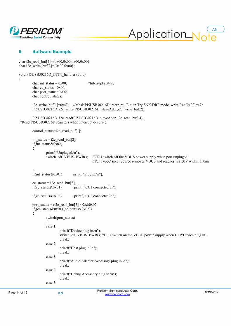
6. Software Example char i2c_read_buf[4]={0x00,0x00,0x00,0x00}; char i2c_write_buf[2]={0x00,0x00}; void PI5USB30216D_INTN_handler (void) { char int_status = 0x00; //Interrupt status; char cc_status =0x00; char port_status=0x00; char control_status; i2c_write_buf[1]=0x47; //Mask PI5USB30216D interrupt. E.g. in Try.SNK DRP mode, write Reg[0x02]=47h PI5USB30216D_i2c_write(PI5USB30216D_slaveAddr,i2c_write_buf,2); PI5USB30216D_i2c_read(PI5USB30216D_slaveAddr, i2c_read_buf, 4); //Read PI5USB30216D registers when Interrupt occurred control_status=i2c_read_buf[1]; int_status = i2c_read_buf[2]; if(int_status&0x02) { printf("Unpluged.\n"); switch_off_VBUS_PWR(); //CPU switch off the VBUS power supply when port unpluged //Per TypeC spec, Source removes VBUS and reaches vsafe0V within 650ms. } if(int_status&0x01) printf("Plug in.\n"); cc_status = i2c_read_buf[3]; if(cc_status&0x01) printf("CC1 connected.\n"); if(cc_status&0x02) printf("CC2 connected.\n"); port_status = (i2c_read_buf[3]>>2)&0x07; if((cc_status&0x01)|(cc_status&0x02)) { switch(port_status) { case 1: printf("Device plug in.\n"); switch_on_VBUS_PWR(); //CPU switch on the VBUS power supply when UFP/Device plug in. break; case 2: printf("Host plug in.\n"); break; case 3: printf("Audio Adapter Accessory plug in.\n"); break; case 4: printf("Debug Accessory plug in.\n"); break; case 5:

Pericom Semiconductor Corp.
www.pericom.com
Page 15 of 15 6/19/2017
AN
AN
printf(Device plug in with active cable.\n”); switch_on_VBUS_PWR(); //CPU switch on the VBUS power supply when UFP/Device plug in. break; default: break; } } i2c_write_buf[1]=0x46; //Unmask PI5USB30216D interrupt. E.g. in Try.SNK DRP mode, write Reg[0x02]=46h PI5USB30216D_i2c_write(PI5USB30216D_slaveAddr,i2c_write_buf,2); } void Initial_prog(void) { i2c_write_buf[1]=0x81; //Reset PI5USB30216D_i2c_write(PI5USB30216D_slaveAddr,i2c_write_buf,2); delay(10);
i2c_write_buf[1]=0x46; //Support Try.SNK DRP mode PI5USB30216D_i2c_write(PI5USB30216D_slaveAddr,i2c_write_buf,2); set_EN_high(); //Enable the PI5USB30216D when EN pin by GPIO control } Void Power_off(void) { //If power-down via powersaving bit i2c_write_buf[1]=0x81; //Enter Power_saving mode when CPU power off PI5USB30216D_i2c_write(PI5USB30216D_slaveAddr,i2c_write_buf,2);
delay(10); /// //If power-down via EN pin set_EN_Low(); //Disable PI5USB30216D via EN pin delay(10); // //System should read byte3 and byte4 to clear them regardless of power-down method PI5USB30216D_i2c_read(PI5USB30216D_slaveAddr, i2c_read_buf, 4);
}