Physics process in Cryog enic Gas Ion Cat...
29
Sivaji Purushothaman GSI, Darmstadt, Germany Physics process in Cryogenic Gas Ion Catcher SMI 2010 21 - 24 April 2010, Stanford
Transcript of Physics process in Cryog enic Gas Ion Cat...

Sivaji PurushothamanGSI, Darmstadt, Germany
Physics process in
Cryogenic Gas Ion Catcher
SMI 201021 - 24 April 2010, Stanford

Outline
• Gas catcher parameters
• Ion mobility
• Electron mobility
• Helium ion species
• Recombination coefficient
• Electric field shielding
• Recombination loss
• Experimental results
• Summary

Ion beam induced ionization
+
+
+
+
+
+
+
+
+
+
+
+
+ +++
+
+
+
++
+
-
-
-
-
--
-
-
-
-
-
--
-
-
-
--
-
-
-
-
-
-
-
Weakly ionized gas
High energy
ion beam
Helium gas
Electrons
-Neutral helium atoms
+Thermalized ions / Hen
+, n = 1, 2 , 3, 4 /metastables
Applied electric field
77 K

Cryogenic Gas Ion Catcher
parameters
1013 mbar @ 293 K
207.4 mbar @ 60 K
10 V cm-1
2.687 X 1019 cm-3
3.72 X 10⁻¹⁹ V cm2
3.72 X 10⁻² Td
101.3 mbar @ 293 K
20.74mbar @ 60 K
100 V cm-1
2.687 X 1018 cm-3
3.72 X 10⁻¹⁷ V cm2
3.72 Td
Electric field (E)
Density (N)
E/N
Td=10-17 V cm2
Temperature
@
Pressure
Operating range : 4 X 10⁻² Td to 4 Td

Ion transport parameters
!
µred = µN
N0
= µT0
P0
Pg
Tg
N = Gas density
Pg = gas pressure
P0 = 1013 mbar
T0 = 273 K
N0= 2.69 X 1019 cm -3
!
µ =vd
E
! = mobilityE = electric field
vd = drift velocity
When ions are in thermal equilibrium with neutrals
low applied electric field
!
µ =qD
kBTg
Nernst-Townsend-Einstein relation
kB = Boltzmann constant
Tg = gas temperature
q = charge of the ion
D = diffusion coefficient
Reduced mobility
!
rrms
= 2Dt
Radial diffusion
!
vd" E
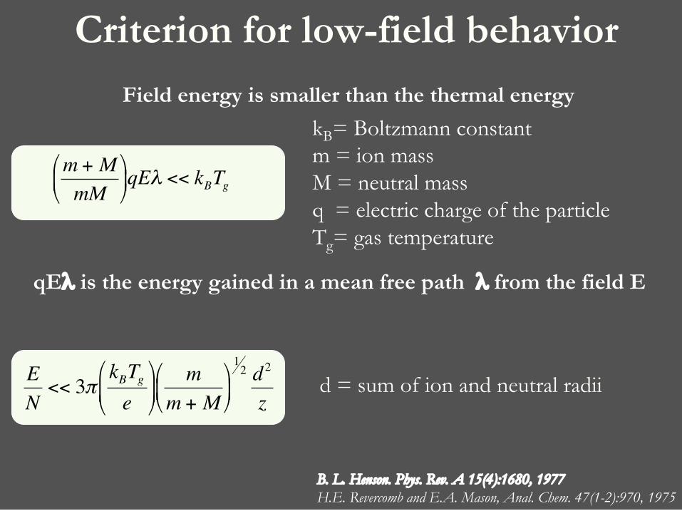
Criterion for low-field behavior
!
m + M
mM
"
# $
%
& ' qE( << kBTg
B. L. Henson. Phys. Rev. A 15(4):1680, 1977
H.E. Revercomb and E.A. Mason, Anal. Chem. 47(1-2):970, 1975
d = sum of ion and neutral radii
!
E
N<< 3"
kBTg
e
#
$ %
&
' (
m
m + M
#
$ %
&
' (
12 d
2
z
qE! is the energy gained in a mean free path ! from the field E
kB= Boltzmann constantm = ion massM = neutral massq = electric charge of the particleTg= gas temperature
Field energy is smaller than the thermal energy

Low field mobility
kB= Boltzmann constantm = ion massM = neutral massq = electric charge of the particle
Tg= gas temperature
!
µ+ =3
16
2"
kBTg
#
$ %
&
' (
121
m+1
M
#
$ % &
' (
12 q
Ng)(1,1)
Tg( )
!
"(1,1)(Tg ) =
1
2 kBTg[ ]3
#2 $ % exp&#
kBTg
'
( ) )
*
+ , ,
0
-
. d#
!
" # = 1$ cos%[ ]0
&
' # (,%( )sin%d%
Average diffusion cross section
"= scattering angle
" = differential crossection for elastic scattering
momentum-transfer (diffusion) cross section
#= kinetic energy
H.E. Revercomb and E.A. Mason, Anal. Chem. 47(1-2):970, 1975

High field mobility
kB= Boltzmann constantm = ion massM = neutral massq = electric charge of the particle
Tg= gas temperature
!
µ+ =3
16
2"
kBTeff
#
$ %
&
' (
121
m+1
M
#
$ % &
' (
12 q
Ng)(1,1)
Teff( )
!
"(1,1)(Teff ) =
1
2 kBTeff[ ]3
#2 $ % exp&#
kBTeff
'
( ) )
*
+ , ,
0
-
. d#
!
" # = 1$ cos%[ ]0
&
' # (,%( )sin%d%
Diffusion collision integral
"= scattering angle
" = differential crossection for elastic scattering
momentum-transfer (diffusion) cross section
#= kinetic energy
H.E. Revercomb and E.A. Mason, Anal. Chem. 47(1-2):970, 1975
L. A. Viehland and E. A. Mason, J. Chem. Phys.,63(7):2913, 1975.
!
kBTeff =3
2kBTg +
1
2mvd
2Effective
temperature

Electron mobility in helium gas
G. Ramanan and G. R. Freeman, J. Chem. Phys., 93(5):3120, 1990.
J. L. Pack and A. V. Phelps, Phys. Rev., 121(3):798, 1961.
R. W. Crompton, M. T. Elford, and R. L. Jory, Aust. J. Phys., 20(4):369, 1967.
!N
[cm
-1 V
-1 s
-1]
E/N [Td]
vd [cm
s-1]

Electron mobility in helium gas
G. Ramanan and G. R. Freeman, J. Chem. Phys., 93(5):3120, 1990.
J. L. Pack and A. V. Phelps, Phys. Rev., 121(3):798, 1961.
R. W. Crompton, M. T. Elford, and R. L. Jory, Aust. J. Phys., 20(4):369, 1967.
!N
[cm
-1 V
-1 s
-1]
E/N [Td]
vd [cm
s-1]

Helium ion species
T = 300 K & P < 1 mbar : He+ dominant
T < 120 K : He3+ is dominant
!
He2
++ 2He" He
3
++ He
!
He+
+ 2He" He2
++ Hefaster than
T = 300 K & P > 5 mbar : He2+ dominant
!
He+
+ 2He" He2
++ He
T < 200 K : He3+ Starts to form
!
He2
++ 2He" He
3
++ He
P. L. Patterson, J. Chem. Phys., 48(8):3625, 1968.
P. L. Patterson, Phys. Rev. A, , 2(4):1154, 1970
R. A. Gerber and M. A. Gusinow, Phys. Rev. A, , 2(4):1154, 1970
J. B. Gerardo and M. A. Gusinow, Phys. Rev. A, 3(1):255, 1971

Helium ions of concern
T = 77 K
E/N < 6 Td
He3+
E/N > 13 Td
He2+ and He+
H. Helm. J. Phys. B, 9(7):1171, 1976.
E/N > 13 Td He3+ are electrically heated and destroyed in collisions
Maximum E/N for CGIC ~ 4 Td
CGIC
E/N Maximum
Dominant He ion is He3+
i(H
e 2+)/
i(H
e3+)
E/N [Td]

Helium ion mobility at 77 K
H. Helm. J. Phys. B, 9(7):1171, 1976.
!re
d [c
m2 V
-1 s
-1]
E/N [Td]

Recombination coefficient
!
" ="2
+ N"3
N [cm-3] = Neutral density
$2 [cm3 s-1] = 2 body recombination coefficient
$3 [cm6 s-1] = 3 body recombination coefficient
!
X+
+ e"
+ B# X + B
X+ : Ion of interest or buffer gas ion
3 body recombination
!
X+
+ e"# X + h$
2 body dissociative recombination
B : Buffer gas atom

He3+ in He gas
80 K and < 65mbar
$ = (3.4±1.4) x 10-6 cm3 s-1
electron temperature dependence
(measured for 80 K < Te < 300 K)
Dominant ionic species at 77 K is He3+
$ of He3+ at 77 K is much larger than $ of He2
+ at 293 K
Recombination coefficient He3+
J. B. Gerardo and M. A. Gusinow Phys. Rev. A, 3(1):255, 1971.
$(Te) = (3.4±1.4) x 10-6 (Te/80)-a cm3 s-1 for 0.98 <a<1.6

Electron temperature
J. Dutton. J. Phys. Chem. Ref. Data, 4(3):577, 1975.
V. M. Atrazhev. J. Phys. D, 17(5):889, 1984.
Te [K
]
E/N [Td]
%#& [eV]
elec
tro
n t
emp
erat
ure electro
n en
ergy

!
" ="2
+ N"3
Theory : $3 ' Tg -2.5
$2 = -0.73 x 10⁻⁷ + 6 x 10⁻¹⁰ Tg
$3 = 3.6 x 10⁻²¹ Tg -2.5
Measured between 50 and 1200 mbar
between 200 - 295
Experimental error
$2 : ~10 %
$3 : ~10 - 20 %
20 % error on estimated $
R. J. van Sonsbeek, R. Cooper, and R. N. Bhave. J. Chem. Phys., 97(3):1800, 1992D. R. Bates.J. Phys. B, 13(13):2587, 1980.L. P. Pitaevskii. Sov. Phys. JETP, 15(5):919, 1962.Y. S. Cao and R. Johnsen. J. Chem. Phys., 94(8):5443, 1991.
$3 ' Tg-2.94
$3 ' Tg-2.54
$3 ' Tg -2.9 for O+ and N+ in helium at 77K, 125 K and 150 K
Neutral density: 2 x 10¹⁹ to 2.9 x 1020 cm-3
Recombination coefficient He3+
ln (T [K])
ln (
1027 $
3 [c
m6 s-1
])

With applied electric field
Steady state positive charge density!
µ" >> µ+
!
Vind =eQ
4"0µ#d2
µ+= positive ion mobility
µ-= electron mobility
Q = Ionization rate density
d = size of the ionization region
E = electric field
Induced voltage
electron and
positive ion mobility
M.Huyse et al., NIM B 187 (2002) 533
+
+
+
+
+
+
+
+
+
++
+
+
+
+
+
+
+
+
+
+
+--
-
-
--
--
-
-
-
-
-
-
--
-
Applied
electric field
Induced
electric field
+
+
+
+
+
+
+
+
+
+
+
+
+ +
+
+
+ +
+

Recombination losses
Q = Ionization rate density$ = e - ion recombination coefficientd = separation between platesµ+
= positive ion mobilityµ-
= electron mobility
E = electric field
Parallel plate ionization chamberformulation
+
+
+
+
+
+ +
+
++
+
+
+
+
+
+
+
+
+
+
+
+- -
-
-
-
-
-
-
-
-
-
--
--
--
-
--
--
-
-
-
Ion extraction efficiency
#extr=1 - f
given f is small
Recombination loss factor
d
E
J. Sharpe. Nuclear radiation detectors. John Wiley & Sons, New York, 1955.
!
f =Q"d2
6v+v#
=Q"d2
6µ+µ#E2

!
frel
=QP
µ"E2Tg
7 / 2
µ- = Electron mobility
E = Electric fieldTg= Gas temperature
Ion extraction efficiency = 1- f = 1 - Kfrel
!
µ+"Tg
P
!
" #Tg$5 / 2
Q = Ionization rate densityP = Gas pressureK = Constant
Relative recombination loss factor
!
f =Q"d2
6µ+µ#E2
Recombination loss factor
S. Purushothaman PhD Thesis, 2008, University of Groningen

Online setup at JYFL

Experimental cell
S. Purushothaman PhD Thesis, 2008, University of Groningen
13 Mev Proton beam
Proton beam
Ionization Region

Experimental cell

Experimental cell
13 Mev Proton beam

S. Purushothaman et al., NIM B 266 (2008) 4488
Efficiency vs. ionization rate density
Combined
efficiency of
ion survival
and
transport
[%]
Ionization rate density [cm-3 s-1]

Effect of electric field shielding
S. Purushothaman et al., NIM B 266 (2008) 4488
Combined
efficiency of
ion survival
and
transport
[%]
Induced voltage (Vind)/ Applied voltage (Vapp)

Relative recombination loss
Combined
efficiency of
ion survival
and transport
[%]
Relative recombination loss frel [arbitrary units]
efficiency = 30(1 - Kfrel)
S. Purushothaman et al., NIM B 266 (2008) 4488

Summary
• Realistic E/N range : 4 X 10⁻² Td to 4 Td
• Electron mobility '(E/N)1/2
• Positive ion mobility falls within Low field mobility regime
• Dominant He ion is He3+
• Recombination coefficient of He3+ ' Tg
-5/2
• High external electric field is necessary to handle high ionization density
Within the context of Cryogenic Gas Ion Catcher

Thanks
P. Dendooven 1
I. Moore 2
K. Peräjärvi 2
H. Penttilä 2
A. Saastamoinen 2
N. Takahashi 3
1 KVI, University of Groningen, Netherlands
2 University of Jyväskylä, Finland
3 Osaka University and Osaka Science Museum, Japan


![Smi cop8[1]](https://static.fdocuments.in/doc/165x107/54959009b47959146b8b4599/smi-cop81.jpg)