PHYSICS OPERATIONS WITH THE DIII-D PLASMA CONTROL SYSTEM · PDF file ·...
9
GA–A26495 PHYSICS OPERATIONS WITH THE DIII-D PLASMA CONTROL SYSTEM by A.W. HYATT, J.R. FERRON, D.A. HUMPHREYS, F.R. CHAMBERLAIN, R.D. JOHNSON, B.G. PENAFLOR, D.A. PIGLOWSKI, J.T. SCOVILLE and M.L. WALKER JULY 2009
Transcript of PHYSICS OPERATIONS WITH THE DIII-D PLASMA CONTROL SYSTEM · PDF file ·...

GA–A26495
PHYSICS OPERATIONS WITH THE DIII-D PLASMA CONTROL SYSTEM
by
A.W. HYATT, J.R. FERRON, D.A. HUMPHREYS,
F.R. CHAMBERLAIN, R.D. JOHNSON, B.G. PENAFLOR,
D.A. PIGLOWSKI, J.T. SCOVILLE and M.L. WALKER
JULY 2009
DISCLAIMER
This report was prepared as an account of work sponsored by an agency of the United States Government. Neither the United States Government nor any agency thereof, nor any of their employees, makes any warranty, express or implied, or assumes any legal liability or responsibility for the accuracy, completeness, or usefulness of any information, apparatus, product, or process disclosed, or represents that its use would not infringe privately owned rights. Reference herein to any specific commercial product, process, or service by trade name, trademark, manufacturer, or otherwise, does not necessarily constitute or imply its endorsement, recommendation, or favoring by the United States Government or any agency thereof. The views and opinions of authors expressed herein do not necessarily state or reflect those of the United States Government or any agency thereof.
GA–A26495
PHYSICS OPERATIONS WITH THE DIII-D PLASMA CONTROL SYSTEM
by
A.W. HYATT, J.R. FERRON, D.A. HUMPHREYS,
F.R. CHAMBERLAIN, R.D. JOHNSON, B.G. PENAFLOR,
D.A. PIGLOWSKI, J.T. SCOVILLE and M.L. WALKER
This is a preprint of a paper to be submited for
publication in IEEE Transactions on Plasma
Science.
Work supported by the U.S. Department of Energy
under DE-FC02-04ER54698
GENERAL ATOMICS PROJECT 30200 JULY 2009

General Atomics Report GA–A26495 1
Physics Operations with the DIII-D Plasma Control System*
A.W. Hyatt, J.R. Ferron, D.A. Humphreys, F.R. Chamberlain, R.D. Johnson, B.G. Penaflor, D.A. Piglowski, J.T. Scoville and M.L. Walker
General Atomics P.O. Box 85608
San Diego, California 92186-5608 USA [email protected]
Abstract—The DIII-D device began operation in 1986, and a fully digital plasma control system (PCS) was implemented in 1993. Over time, the success of the PCS to exploit the inherent versatility of the DIII-D device led to a philosophy of using the PCS to control all available plasma system actuators. This made the PCS a very powerful physics tool that is at the core of Physics Operations at DIII-D. The complexity of the DIII-D device and all the systems the PCS must control makes proper setup of the PCS for new experiments a daunting task. A cadre of physicists specially trained in PCS operation forms the bulk of the Physics Operations staff at DIII-D. They are the interface between experimental plans and successful execution and, as such, are a critical component of each experiment. Physics Operations is also a set of tools and procedures. We will briefly examine some of those tools, such as the TokSys control design and modeling environment, and the ‘smart’ PCS setup checklist, that greatly reduces human error in reconfiguring the PCS for a new experiment. We will examine the procedures that allow efficient use of those tools and some of the human factors that can affect productivity.
Keywords: plasma; control; operations; tokamak
I. INTRODUCTION The DIII-D tokamak device was designed and built to test,
among other things, the stability and confinement properties of plasmas of many different shapes. It is capable of producing plasmas of a wide variety of poloidal cross-sectional shapes using its 18 independent poloidal field (PF) shaping coils [1]. An abundance of auxiliary heating systems, including about 20 MW from seven tangentially directed neutral beams (NB), about 5 MW from poloidally and toroidally steerable 110 GHz gyrotrons, and about 3 MW from three 60–120 MHz fast wave systems, allow DIII-D to reach stability limits in all plasma shapes, and to some extent control the radial profiles of the plasma current, pressure and toroidal rotation to explore and expand those limits.
Complementing these actuators are a wide variety of plas-ma measurement systems such as poloidal flux loops and field probes, laser interferometry density measurements, Thomson scattering measurements of the electron density and tempera-ture profiles, motional Stark effect (MSE) polarimetry mea-surements of the plasma current density profiles, charge
exchange recombination (CER) spectroscopy measurements of ion temperature and toroidal and poloidal velocity profiles and more.
The plasma control system (PCS) [2] receives real-time raw data, or in some cases partially analyzed data, from each of these measurement systems, as well as from many other plasma actuator systems and measured quantities relevant to plasma actuators or the plasma state. The PCS analyzes these data in real time to measure various plasma state quantities and uses the results to control the actuator systems so that those quanti-ties conform to programmed targets in real time. Since the introduction of a digitally based PCS in 1993, when only the plasma’s line average density, current and approximate boundary were controlled, more and more actuator and measurement systems have been installed at DIII-D and brought under PCS control.
The present PCS is a complex instrument, requiring special-ly trained personnel to configure it properly for the wide range of plasmas and experiments it must produce and control. At DIII-D, these personnel are drawn from the staff of experiment-al plasma physicists and form the Physics Operators group. In addition to configuring the PCS for specific experiments, Physics Operators also determine the day-to-day hardware configurations of many of the actuator systems, including but not limited to the PF coils and their power supplies, that are required for particular experiments. Specialists within the Physics Operators group also design and implement new real-time data analysis and control algorithms to make use of new or expanded diagnostic signals and actuator systems. Implementation of an appropriately flexible and powerful algo-rithm in the PCS is a crucial enabling step allowing exploration of new physics with new real-time diagnostics and actuators.
Physics Operations encompasses a complex set of tools, such as the PCS, a set of formal and informal procedures that allow efficient use of those tools, and the group of Physics Operators that use those tools and procedures to design and run experiments as well as design and add new capabilities to the PCS. Supporting Physics Operations is a small group of computer specialists that maintain and expand the PCS, and a small group of control specialists that design and implement new control algorithms in the PCS.
*This work was supported by the US Department of Energy under DE-FC02-04ER54698.

A.W. Hyatt et al. Physics Operations with the DIII-D Plasma Control System
General Atomics Report GA–A26495 2
II. PHYSICS PRODUCTIVITY AT DIII-D Consider the simple cyclical model of physics production
shown in Fig. 1. The process can be viewed as beginning with physics questions that arise when existing theories and results do not align well, often leading to the design of new experi-ments at DIII-D. Sometimes the existing ways to use the de-vice, i.e., the actuators, control capabilities, analysis methods, diagnostics, etc., are found sufficient to design the new experi-ment. Sometimes new capabilities need to be designed and added. The experiment is then run, producing results that often lead to new questions. This leads to efforts to upgrade/expand existing capabilities or add new capabilities. These improve-ments may include additional diagnostics, better or different ways to analyze the data from existing measurements, and expanded or new actuator capabilities, including new ways to use existing actuators. When these new tools are implemented, the experiments can be run, and their results can then lead to new physics questions, continuing the cycle. The net output of the physics productivity cycle is the scientific understanding that accrues when a widening range of physics becomes acces-sible to experiment using more precise measurements, more precise control of conditions, and more successful experimental attempts within an allotted time frame.
Figure 1. A cyclical representation of physics productivity at DIII-D. Each
phase of the cycle contributes to overall physics productivity. Each phase interacts in a complex way with the other phases. For instance, productivity generally increases with better experiments, which are driven by ‘better’ questions, ‘better’ experiment design, and/or when better tools become available.
Physics Operations is directly involved at all phases of the physics productivity cycle at DIII-D. Physics Operators are drawn from the DIII-D community of research scientists and are, therefore, part of the dialog that brings physics questions to the stage where new experiments are discussed and designed. Many of the topical research groups at DIII-D have a Physics Operator as a member. This gives those groups access at an early stage to expertise on the up-to-date capabilities of the device and the PCS, and to the characteristics of the wide range of plasmas that have been produced at DIII-D.
Physics Operations is also involved in designing and implementing better control tools. A new tool, like real-time PCS measurement and control of plasma pressure, can enable plasma experiments of higher precision when a significant plasma parameter is held fixed as others are deliberately varied. Experiments that previously were contemplated but rejected because of the impractical amount of time needed to get a good data set become possible with a few shots.
Finally, it is Physics Operations’ responsibility to provide the proper plasma conditions during experiments. To this end, control algorithms and hardware configurations must be chosen and properly programmed. As results emerge and conditions change during the experiment, the Session Leader, who is in charge of carrying out the experimental plan, may decide to pursue an unplanned tack. Then the advice of the Physics Operator regarding realistic possibilities can prove essential.
III. PHYSICS OPERATIONS: TOOLS AND PROCEDURES At DIII-D the tools and procedures of Physics Operations
have been both expanded and re-examined over the years with the twin goals of expanding capabilities and increasing produc-tivity. Tools are important because they are the means whereby the Physics Operator interacts with the device. Expanding and refining the tools available to the Physics Operator brings ex-panded physics experiment possibilities to the Session Leader. Procedures are especially important as they can codify hard won best practices into standard practices.
A. Tools The digital plasma control system [2] is Physics Opera-
tions’ most important tool. It has undergone extensive and con-tinuous improvement and expansion since it was first devel-oped and introduced at DIII-D in 1993. It started with two parallel CPUs and now consists of up to 19 parallel CPUs (depending on the experimental needs and configuration). In 1993 the PCS controlled only the plasma shape, i.e., the plasma’s poloidal cross-sectional boundary, the plasma line averaged density and the toroidal current. A major improve-ment introduced in 1996 was the introduction of plasma shape control using a real-time Grad-Shafranov plasma equilibrium reconstruction algorithm based on the free boundary equili-brium code EFIT [3]. Real-time EFIT (RTEFIT) within the PCS allowed more precise measurement of the plasma bound-ary, and more importantly opened up access to all of the plasma equilibrium quantities that RTEFIT can provide, given appro-priate data. This capability led to introducing a wide range of profile data into the PCS to more accurately constrain the real-time equilibrium solution and/or provide new measurements that can be used for control purposes. These profile data in-clude MSE poloidal field measurements, CER ion temperature and toroidal velocity measurements, Thomson scattering elec-tron density and temperature measurements, and others. Combining RTEFIT with the PCS control of new actuators including neutral beams (NB) and gyrotrons, enabled feedback control of many new quantities, such as plasma beta, and toroidal velocity or temperature at specified radial positions.
Two examples of PCS feedback control are given in Fig. 2. The DIII-D NBs are tangentially directed, so they input net mo-mentum as well as energy to the plasma. In 2005, two of the NBs were redirected to input momentum opposite to the other five NBs. This arrangement to some extent breaks the coupling of energy and momentum input. For instance, with two NBs injected co-linearly with the plasma current, and two NBs injected counter, it is possible to drive the plasma toroidal velocity in either direction while maintaining the same energy input. Fig. 2(a) displays this capability graphically. Here nor-malized plasma beta,
€
βN , and the plasma toroidal velocity

A.W. Hyatt et al. Physics Operations with the DIII-D Plasma Control System
General Atomics Report GA–A26495 3
Figure 2. (a) Simultaneous feedback control of plasma normalized beta,
€
βN , and toroidal rotation is done with PCS control of co/counter-neutral beams. The upper trace shows measurement (red) and target (black)
€
βN . The lower trace shows measured (red) and target (black) toroidal rotation. (b) ECCD suppression of the 2/1 NTM is effective only when deposited within the NTM island. The upper trace shows island width evolution. The bottom trace shows the initial alignment of the ECCD deposition’s radial location with the
€
q=2 surface and then subsequent tracking as the
€
q=2 surface location evolves.
measured at a fixed radial location within the plasma are simul-taneously feedback controlled by the PCS. The upper trace shows a
€
βN target overlaid with the real-time EFIT measure-ment, while the lower trace shows a rotation target overlaid with the real-time CER rotation measurement. Note that
€
βN is held fixed while the toroidal rotation is controllably varied. Fig. 2(b) displays PCS-controlled suppression of a neoclassical tearing mode (NTM) of poloidal/toroidal mode numbers 2/1 using localized electron cyclotron current drive (ECCD) at the NTM island location. This control is termed ‘Search and Sup-press’. The PCS employs a real-time spectral decomposition of magnetic fluctuation signals to determine the size of the 2/1 is-land. When the island size reaches a critical value, the PCS al-gorithm begins ‘searching’ by translating the plasma major ra-dius in discrete steps until the 2/1 signal disappears. At that point, the real-time EFIT measurement of the
€
q=2 flux sur-face’s radial location relative to the calculated ECCD deposi-tion location becomes the target. Then the plasma is radially translated to maintain that relationship while the
€
q=2 flux sur-face and ECCD deposition location changes during the discharge.
The PCS can enhance productivity not just by expanding the precision and reach of the physics questions DIII-D can attack, but also by controllably aborting discharges that are at risk of disrupting or even just entering confinement regimes
that require excess fueling gas to maintain a target density. This condition can arise when a discharge suffers a locked mode (LM). Many types of plasma experiments at DIII-D are sensi-tive to the carbon tiles’ absorbed reservoir of fuel gas, and plas-ma disruptions or even high fueling gas rates tend to overload that reservoir unacceptably for these experiments. Once that happens, it may take from one to several ‘cleanup’ discharges to sufficiently unload the reservoir for the experiment to con-tinue. The PCS avoids this loss of experiment time by monitor-ing selected conditions such as the toroidally odd mode Mirnov signal amplitude and/or locked mode detector amplitude and/or plasma
€
βN . When the selected signal(s) exceeds (or drops below) a programmed level for a specified amount of time the PCS switches one or more actuator systems’ pre-programmed targets to a different set of pre-programmed targets, such as an immediate plasma current rampdown. Then the plasma is ter-minated before a possible disruption. This facility is, in effect, an asynchronous trigger that can be set to fire on any signal(s) or condition the PCS monitors, and when triggered can set the PCS on an alternate experimental path dictated by that condi-tion. It is thus a prototype for a general off normal event and fault response architecture.
Programming the PCS to pursue a new experiment can be a daunting task. There are dozens of algorithms to select and hundreds of programmable time dependent targets and required parameter settings for those algorithms. Fortunately, most new experiments are extensions of past experiments or based on ex-isting discharges. Since every discharge’s PCS configuration is archived when run, it is possible to simply restore the PCS to that configuration, greatly reducing the amount of waveform programming needed when running scenarios. Nevertheless, system modifications or accumulated experience sometimes re-quire us to modify some targets and parameters even for recent-ly executed discharges. This creates possibilities for program-ming mistakes, even when trying to reproduce relatively recent discharges. In order to ameliorate this and other known sources of PCS setup errors, the PCS employs an interactive checklist.
The PCS checklist is started by the Physics Operator in the morning before the experiments begin. It guides the Operator through standardized set of actions, such as magnetic integrator calibrations, a low power test of all the major tokamak power supplies, and the responses of the gas injection systems. Then the PCS is loaded with files that specify the device hardware systems’ configurations as performed by the DIII-D Operations technicians using the Physics Operator’s instructions. At this point, the checklist configures itself for compatibility with the input hardware configurations. The Physics Operator then loads in the starting experimental PCS configuration setup. This may simply restore a previous discharge’s setup in toto, or may load in a completely new setup. As the Operator proceeds through the checklist, internal checks are performed and items that are inconsistent with the hardware configurations are flagged. Where appropriate, the relevant items are displayed on the PCS interface for correction. The checklist also helps the Operator set up the best practices programming for some standardized plasma phases used by all discharges such as the plasma breakdown and initial current rampup and the program-ming of the magnetic error field reduction system. Since the incorporation of this checklist in 2004 errors attributable to
A.W. Hyatt et al. Physics Operations with the DIII-D Plasma Control System
General Atomics Report GA–A26495 4
incorrect programming of items covered by the interactive checklist have significantly decreased.
As noted above, the PCS performs a significant amount of real-time analysis. Display of selected results of this analysis in real time can be extremely valuable to both experimental teams and Physics Operators. This is important since the progress of the experiment depends critically on the timely accessibility of analyzed data so that the Session Leader and the experimental team can decide how to proceed or the Physics Operator can begin to troubleshoot problems. Given that that the device and data systems are ready for another discharge about 12 minutes after the last one, getting the data a few minutes earlier can be very helpful. The PCS has seven computer monitor screens ar-ranged above the Physics Operator’s station plus three large video screen monitors above those each dedicated to the real-time display of selected PCS data. The waveforms that are displayed are configurable by the Physics Operator but are usually comprised of about 50 signals plus a nearly real-time display of the plasma cross section displayed on the large video screen. Some of the signals are set to data of special interest to the Session Leader, but the majority are signals that have been shown by experience to be most valuable in identifying and troubleshooting problems.
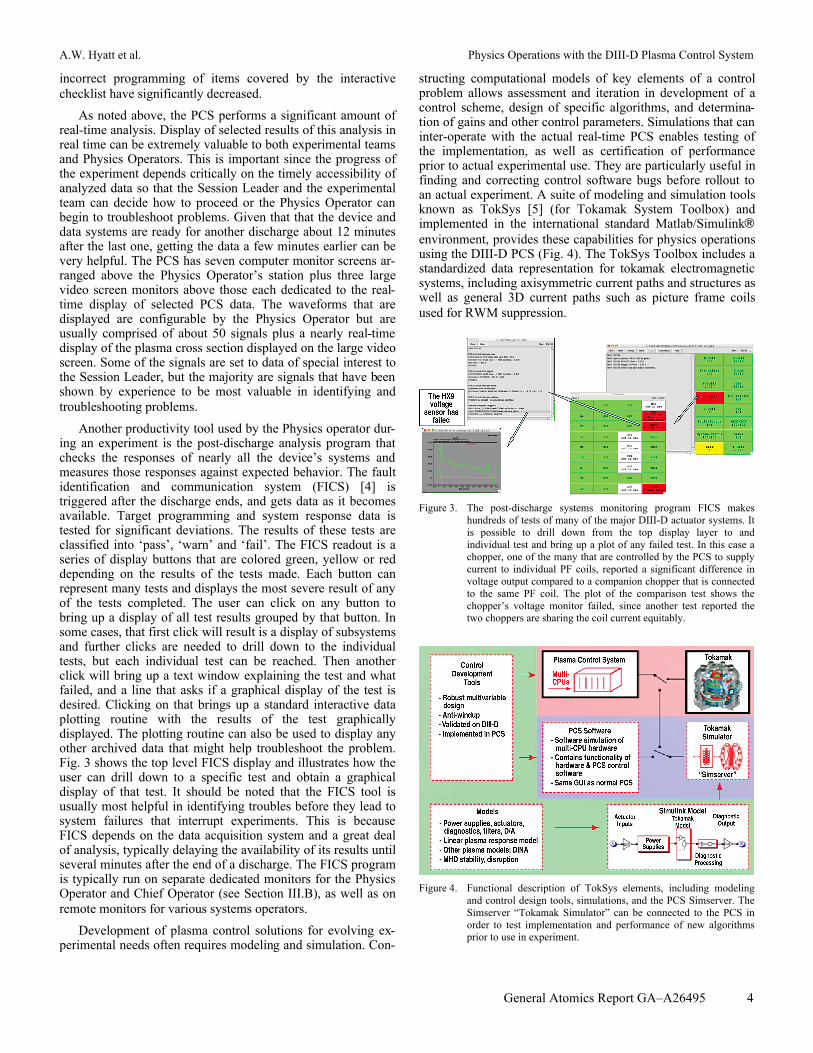
Another productivity tool used by the Physics operator dur-ing an experiment is the post-discharge analysis program that checks the responses of nearly all the device’s systems and measures those responses against expected behavior. The fault identification and communication system (FICS) [4] is triggered after the discharge ends, and gets data as it becomes available. Target programming and system response data is tested for significant deviations. The results of these tests are classified into ‘pass’, ‘warn’ and ‘fail’. The FICS readout is a series of display buttons that are colored green, yellow or red depending on the results of the tests made. Each button can represent many tests and displays the most severe result of any of the tests completed. The user can click on any button to bring up a display of all test results grouped by that button. In some cases, that first click will result is a display of subsystems and further clicks are needed to drill down to the individual tests, but each individual test can be reached. Then another click will bring up a text window explaining the test and what failed, and a line that asks if a graphical display of the test is desired. Clicking on that brings up a standard interactive data plotting routine with the results of the test graphically displayed. The plotting routine can also be used to display any other archived data that might help troubleshoot the problem. Fig. 3 shows the top level FICS display and illustrates how the user can drill down to a specific test and obtain a graphical display of that test. It should be noted that the FICS tool is usually most helpful in identifying troubles before they lead to system failures that interrupt experiments. This is because FICS depends on the data acquisition system and a great deal of analysis, typically delaying the availability of its results until several minutes after the end of a discharge. The FICS program is typically run on separate dedicated monitors for the Physics Operator and Chief Operator (see Section III.B), as well as on remote monitors for various systems operators.
Development of plasma control solutions for evolving ex-perimental needs often requires modeling and simulation. Con-
structing computational models of key elements of a control problem allows assessment and iteration in development of a control scheme, design of specific algorithms, and determina-tion of gains and other control parameters. Simulations that can inter-operate with the actual real-time PCS enables testing of the implementation, as well as certification of performance prior to actual experimental use. They are particularly useful in finding and correcting control software bugs before rollout to an actual experiment. A suite of modeling and simulation tools known as TokSys [5] (for Tokamak System Toolbox) and implemented in the international standard Matlab/Simulink® environment, provides these capabilities for physics operations using the DIII-D PCS (Fig. 4). The TokSys Toolbox includes a standardized data representation for tokamak electromagnetic systems, including axisymmetric current paths and structures as well as general 3D current paths such as picture frame coils used for RWM suppression.
Figure 3. The post-discharge systems monitoring program FICS makes
hundreds of tests of many of the major DIII-D actuator systems. It is possible to drill down from the top display layer to and individual test and bring up a plot of any failed test. In this case a chopper, one of the many that are controlled by the PCS to supply current to individual PF coils, reported a significant difference in voltage output compared to a companion chopper that is connected to the same PF coil. The plot of the comparison test shows the chopper’s voltage monitor failed, since another test reported the two choppers are sharing the coil current equitably.
Figure 4. Functional description of TokSys elements, including modeling
and control design tools, simulations, and the PCS Simserver. The Simserver “Tokamak Simulator” can be connected to the PCS in order to test implementation and performance of new algorithms prior to use in experiment.

A.W. Hyatt et al. Physics Operations with the DIII-D Plasma Control System
General Atomics Report GA–A26495 5
An extensive library of 2D and 3D Green’s function calculation tools is provided, including specialized tools for tokamak-specific geometries (e.g., coils with parallelogram cross-sections, toroidal conic geometries, complex current-sharing structures and circuit networks, etc.). Plasma response models are tightly coupled to equilibria calculated by either EFIT or TEQ, but can be derived from general equilibrium results as well. These models include linear rigid
€
R /Z / I p responses or fully nonrigid (deformable plasma) responses with a variety of available constraints appropriate for different plasma regimes. Tools for control design include position and shape estimators from magnetic measurements and gain design codes. Specialized shape control design codes employ LQG, H-infinity, and PID gain space search approaches.
Controller solutions not amenable to linear design algo-rithms rely heavily on TokSys simulations for development (Fig. 5). TokSys simulations in the Simserver form are then coupled with the PCS itself to verify implementation and confirm performance (Fig. 4).
B. Procedures Three main areas of responsibility are recognized in the
structure of DIII-D experiments: The physics research community represented by the Session Leader; Physics Operations, represented by the Physics Operator; and DIII-D Operations, represented by the Chief Operator. The physics research community proposes, selects, schedules and plans the experiments, Physics Operations is responsible for device setup decisions and configuring the PCS to best perform those experiments, and DIII-D Operations installs, maintains and sets up the hardware, and is responsible for ensuring that the facility is used safely. These three groups communicate and consult with each other at all stages of the process in order to best formulate and pursue the overall experimental plan. Given DIII-D Operations’ safety responsibility, both for personnel and for all systems, the Chief Operator is at all times in charge of the device. Any actions taken by the Physics Operator must be in accord with the Chief Operator. Often the Physics Operator helps the experimenter and DIII-D Operations negotiate ways to use the device that is both safe and advances the experimenter’s goals, both in planning and executing the experiment. A comprehensive set of procedures governs this relationship and the ways in which these two operators can permit or restrict actions by various experimental team members or diagnosticians and technicians (e.g., access to the machine hall between shots).
Another set of formal and informal procedures allow Physics Operators to efficiently use the PCS. Some procedures, such as producing and updating checklists for the many actions a Physics Operator must complete during the setup and execution of an experiment, have been a part of Physics Operations from the beginning. Others, such as the addition of a “Continuing Education” element to the semi-regular Physics Operators meetings, were added after the need for them became clear. In all cases, new or modified procedures were implemented to aid the Physics Operator and thereby increase the overall physics productivity at DIII-D.
Figure 5. Illustration of TokSys simulation for development of NTM control
algorithm. TokSys modules describe plasma vertical motion to align the NTM island with the ECCD location (Zec), the response of the island to ECCD deposition, and the measurement of the island location (Zq) by RTEFIT with MSE.
One of the core procedures at DIII-D is to provide two Physics Operators in the Control Room during experiments. The First Operator is responsible for working with the Session Leader before the experiment, to help plan the experiment and to determine the hardware and software configurations needed to execute the experiment. He communicates to Tokamak Operations the needs of the experiment in a timely manner, makes sure the device is fully set up for the coming experi-ment, and programs the PCS during the experiment. The Second Operator is the First Operator’s assistant and works under his direction. The Second Operator’s role is generally largest in the morning when many of the hardware configura-tion changes and setups need to be made and when the readi-ness of the device for the coming experiment needs to be assessed. He is there to assist when the demands of the experi-ment threaten to overwhelm the First Operator and to help troubleshoot problems as they arise. It is always better to have more trained eyes and experience when investigating problems.
We have found that Physics Operations are most effective when the First Operator for a given experiment is drawn from the experimental group that proposed the experiment. When this is not possible, the next best thing is to have a First Operator who has done similar experiments before, and/or is interested in the scientific aspects of the experiment. To facilitate pairing First Operators with experiments, Physics Operators meetings are held before an experimental run period begins, and provide an opportunity for Physics Operators to discuss and self-select First Operator assignments. Second Operator assignments are similarly discussed and self-selected, though in many cases they are assigned based on personnel availability.
During these meetings, improvements, bug fixes, patches, new algorithms, etc., added to the PCS can be introduced to all Physics Operators. They can request clarifications and changes to the checklists and procedures in place. Operators can discuss the problems encountered since the last meeting and ways to deal with those problems. These meetings are also a good place to re-educate the Operators on the potential and usage of some of the more complex algorithms in the PCS that have many different possible configurations and usages. Results from these meetings are uploaded to a Physics Operations website. The

A.W. Hyatt et al. Physics Operations with the DIII-D Plasma Control System
General Atomics Report GA–A26495 6
website contains the latest experimental schedule with First and Second Operator assignments, up-to-date checklists, and instructional memos available for download.
Physics Operators are responsible for maintaining logbook entries of intent and results for each discharge during an experiment and an overall summary at end of day. The day’s summary contains the specifics of the device setup and PCS configuration, what was attempted and what was completed, as well as problems encountered and ways to fix them or maneuver around them. The logbook is accessible from the web, and entries are added to a searchable SQL database. It can provide valuable information on past experiments and tips on how to get them to work again with a minimum of trial and error. The Session Leader and Chief operator are responsible for additional logbook entries with similar accessibility.
Various hardware systems, including the tokamak itself, undergo periodic maintenance and occasional upgrades and reconfiguration. Obsolete equipment is replaced, and new controls for the hardware are implemented. This can change the way systems respond to PCS commands, and can change previous requirements for optimal operation, sometimes in ways that are incremental. These changes can accumulate to the point where standard operational practices are no longer optimal. This has been found to be the case with the plasma breakdown and the initial current rampup. This can affect the repeatability of experiments across years. We now re-optimize standard operational practices at the start of each year’s experimental campaign to combat any creeping degradation.
C. Human Factor The tools and procedures outlined above are to some extent
the result of experimentation and optimization over time. Some cases, particularly the bottom-up scheduling of First Operators, are the result of consideration of ‘human factor’ issues: those who are more invested in an experiment are more likely to do a better job with it. One key aspect of experimental operations heavily dependent on human factors is the layout of the Control Room, especially the placement of the Physics Operator, the Session Leader, and the Tokamak Operator. Another is the introduction of an easily viewable timer that counts down the time for various delays that inhibit the next experiment from starting, such as hardware cooldown, data acquisition and between-shot first wall cleaning glow discharges.
Both of these items play significant roles in addressing the observation that the next discharge often does not start as soon as it can. Delay in starting a new discharge translates to fewer discharges in a day and reduced physics productivity. Although there are many contributing factors to this delay, a key cause is inattention to the passage of time by the Session Leader and/or the Physics Operator. The next shot must be initiated 8 minutes after the last to achieve DIII-D’s minimum discharge cycle time of 12 minutes. If the Session Leader takes time deciding his next move, the Physics Operator may end up with several minutes of waiting time before the next discharge can start. He may then by chance become involved in the conversations that often arise between the Chief Operator and Tokamak Operations staff, or with others. Similar distractions may envelop the Session Leader and Chief Operator. To initiate the
next shot, the Chief Operator must first inform the Physics Operator that the device is ready, and the Physics Operator must ask the Chief Operator for the next shot to commence. This, in turn, requires readiness and approval by the Session Leader. With three different people each with different responsibilities and duties it is not surprising that the communication required to get the next discharge under way sometimes breaks down. One effective solution to this problem was to move the Physics Operator closer to the Session Leader and farther away from the Chief Operator. This increased clear communication between Physics Operator and Session Leader and lessened distraction possibilities. Another solution was to prominently display the countdown timer and make it available on every monitor so the Session Leader and Physics Operators are constantly reminded of the interval remaining before the next discharge can be started.
IV. CONCLUSIONS Physics Operations is one of the three distinct pillars of
scientific productivity at DIII-D, along with DIII-D Operations and the physics research community. Each have their own distinct set of responsibilities, and they must mesh well to successfully execute experiments. Physics Operations in some sense is the interface between the experimental goals of the research community and the facility operated by DIII-D Operations and is charged with producing the plasmas needed for experiments. This is a complex and demanding task that requires among other things a mastery of the Plasma Control System and a broad understanding of the various ways the DIII-D device can be configured and what kinds of plasmas it can produce. Over the years, Physics Operations has designed and adopted many tools and procedures that enhance and extend Physics Operations’ capabilities to use the DIII-D device productively. The single most important tool is the PCS, but using it effectively has driven the evolution of procedures such as regular two-way informational meeting and adoption of other tools such as the TokSys set of control design and simulation codes. Human factor issues have been seen to impact productivity. Physics Operations at DIII-D today is the result of many years of experience designing and expanding a tool set to produce the desired plasmas, acquiring experience among the Physics Operators, instituting procedures that take account of human factors, and empowering the Physics Operators to productively advance the physics goals of the research community.
REFERENCES [1] J. L. Luxon, "A design retrospective of the DIII-D tokamak," Nucl.
Fusion vol. 42, p. 614, 2002. [2] J. R. Ferron, et al., “A flexible software architecture for tokamak
discharge control systems,” in Proc. 16th IEEE/NPSS Symp. on Fusion Engin., Champaign, Illinois (Institute of Electrical and Electronics Engineers, Inc., Piscataway, 1996) vol. 2, p. 870.
[3] J. R. Ferron, et al., “Realtime equilibrium reconstruction for tokamak discharge control,” Nucl. Fusion, vol. 38, p. 1055, 1998.
[4] J. T. Scoville, M. L. Walker, “Automatic fault-checking system on the DIII-D tokamak,” Fusion Sci. Technol., vol. 47, p. 774, 2005.
[5] D. A. Humphreys, et al., “Development of ITER-relevant plasma control solutions at DIII-D,” Nucl. Fusion, vol. 47, p. 943, 2007.