Physics-Inspired Topology Changes for Thin Fluid …turk/my_papers/thin_fluid_features.pdf ·...
8
Physics-Inspired Topology Changes for Thin Fluid Features Chris Wojtan Georgia Institute of Technology Nils Th ¨ urey ETH Z ¨ urich Markus Gross ETH Z ¨ urich Greg Turk Georgia Institute of Technology Figure 1: Our algorithm efficiently produces detailed thin sheets and liquid droplets, even with low-resolution fluid simulations — The main corridor in this example is only 30 fluid cells wide. Abstract We propose a mesh-based surface tracking method for fluid anima- tion that both preserves fine surface details and robustly adjusts the topology of the surface in the presence of arbitrarily thin features like sheets and strands. We replace traditional re-sampling methods with a convex hull method for connecting surface features during topological changes. This technique permits arbitrarily thin fluid features with minimal re-sampling errors by reusing points from the original surface. We further reduce re-sampling artifacts with a subdivision-based mesh-stitching algorithm, and we use a higher order interpolating subdivision scheme to determine the location of any newly-created vertices. The resulting algorithm efficiently produces detailed fluid surfaces with arbitrarily thin features while maintaining a consistent topology with the underlying fluid simula- tion. Keywords: surface tracking, topology changes, fluid dynamics, deforming meshes 1 Introduction In the recent past, researchers have developed several impressive techniques for tracking the surface of a flowing liquid [Osher and Fedkiw 2002; Bargteil et al. 2006; Enright et al. 2002]. Tradition- ally, these surface tracking methods impose topological changes upon the fluid surface whenever surface features are smaller than the computational resolution. These topological changes cause droplets to pinch off, thin sheets to rupture, and small features to vanish when they become smaller than a predefined length. In contrast, the topological behavior of liquid surfaces in the real world does not depend upon a single spatial threshold. Instead, these splits and merges are closely linked to the geometry and mo- tion of the fluid. For example, thin cylinders of liquid tend to break up into droplets in the presence of large surface tension; this phe- nomenon is known as a Rayleigh-Plateau instability, and it is caused by a positive feedback loop between the decreasing cylinder radius and increasing tension forces. As a result, liquid jets and spindles along the boundary of a liquid sheet will reliably break apart as soon as they become thin enough for the surface tension forces to dominate the inertia forces [De Gennes et al. 2004; De Luca and Costa 2009]. However, the main body of a liquid sheet is actually stabilized by surface tension forces, so it will resist rupturing until it becomes microscopically thin and torn apart by van der Waals forces [Ivanov 1988]. Thin sheets of air, on the other hand, tend to immediately break up due to a Rayleigh-Taylor instability when surrounded by bodies of denser liquid [Rayleigh 1883]. Based on these observations, we believe it is physically incorrect to induce topological splits and merges based on a single grid reso- lution. In order to faithfully recreate the phenomena mentioned in the previous paragraph, we have devised the following physically- inspired rules for the topological persistence of fluid features in an animation: 1. Thin sheets of air should be quickly deleted. 2. Thin sheets of liquid should never rupture. 3. Thin spindles of liquid should break up at a scale defined by the animator. In this paper, we will use these guidelines to develop a physically- inspired model for handling topological changes in liquid simula- tions. Our work begins with a method for explicitly tracking a fluid sur- face, similar to the methods of Du et al. [2006] and Wojtan et al. [2009]. These techniques deform a high-resolution surface mesh and locally detect and correct topological inconsistencies by re- sampling from a grid-based signed distance function. This tac- tic successfully preserves high resolution surface details in topo- logically simple regions of the surface, but it relies on march- ing cubes [Lorensen and Cline 1987] to re-sample from a signed- distance function at sites where topology changes occur. Unfortu- nately, because marching cubes cannot represent features smaller than a grid cell, this approach cannot perform topological changes on thin features without deleting large sections of the surface at a time. The technique presented by M ¨ uller [2009], on the other hand, is ca-
Transcript of Physics-Inspired Topology Changes for Thin Fluid …turk/my_papers/thin_fluid_features.pdf ·...
Physics-Inspired Topology Changes for Thin Fluid Features
Chris WojtanGeorgia Institute of Technology
Nils ThureyETH Zurich
Markus GrossETH Zurich
Greg TurkGeorgia Institute of Technology
Figure 1: Our algorithm efficiently produces detailed thin sheets and liquid droplets, even with low-resolution fluid simulations — The maincorridor in this example is only 30 fluid cells wide.
Abstract
We propose a mesh-based surface tracking method for fluid anima-tion that both preserves fine surface details and robustly adjusts thetopology of the surface in the presence of arbitrarily thin featureslike sheets and strands. We replace traditional re-sampling methodswith a convex hull method for connecting surface features duringtopological changes. This technique permits arbitrarily thin fluidfeatures with minimal re-sampling errors by reusing points fromthe original surface. We further reduce re-sampling artifacts witha subdivision-based mesh-stitching algorithm, and we use a higherorder interpolating subdivision scheme to determine the locationof any newly-created vertices. The resulting algorithm efficientlyproduces detailed fluid surfaces with arbitrarily thin features whilemaintaining a consistent topology with the underlying fluid simula-tion.
Keywords: surface tracking, topology changes, fluid dynamics,deforming meshes
1 Introduction
In the recent past, researchers have developed several impressivetechniques for tracking the surface of a flowing liquid [Osher andFedkiw 2002; Bargteil et al. 2006; Enright et al. 2002]. Tradition-ally, these surface tracking methods impose topological changesupon the fluid surface whenever surface features are smaller thanthe computational resolution. These topological changes causedroplets to pinch off, thin sheets to rupture, and small features tovanish when they become smaller than a predefined length.
In contrast, the topological behavior of liquid surfaces in the realworld does not depend upon a single spatial threshold. Instead,
these splits and merges are closely linked to the geometry and mo-tion of the fluid. For example, thin cylinders of liquid tend to breakup into droplets in the presence of large surface tension; this phe-nomenon is known as a Rayleigh-Plateau instability, and it is causedby a positive feedback loop between the decreasing cylinder radiusand increasing tension forces. As a result, liquid jets and spindlesalong the boundary of a liquid sheet will reliably break apart assoon as they become thin enough for the surface tension forces todominate the inertia forces [De Gennes et al. 2004; De Luca andCosta 2009]. However, the main body of a liquid sheet is actuallystabilized by surface tension forces, so it will resist rupturing untilit becomes microscopically thin and torn apart by van der Waalsforces [Ivanov 1988]. Thin sheets of air, on the other hand, tendto immediately break up due to a Rayleigh-Taylor instability whensurrounded by bodies of denser liquid [Rayleigh 1883].
Based on these observations, we believe it is physically incorrectto induce topological splits and merges based on a single grid reso-lution. In order to faithfully recreate the phenomena mentioned inthe previous paragraph, we have devised the following physically-inspired rules for the topological persistence of fluid features in ananimation:
1. Thin sheets of air should be quickly deleted.
2. Thin sheets of liquid should never rupture.
3. Thin spindles of liquid should break up at a scale defined bythe animator.
In this paper, we will use these guidelines to develop a physically-inspired model for handling topological changes in liquid simula-tions.
Our work begins with a method for explicitly tracking a fluid sur-face, similar to the methods of Du et al. [2006] and Wojtan etal. [2009]. These techniques deform a high-resolution surface meshand locally detect and correct topological inconsistencies by re-sampling from a grid-based signed distance function. This tac-tic successfully preserves high resolution surface details in topo-logically simple regions of the surface, but it relies on march-ing cubes [Lorensen and Cline 1987] to re-sample from a signed-distance function at sites where topology changes occur. Unfortu-nately, because marching cubes cannot represent features smallerthan a grid cell, this approach cannot perform topological changeson thin features without deleting large sections of the surface at atime.
The technique presented by Muller [2009], on the other hand, is ca-

pable of performing topological changes on some types of thin fea-tures, because it uses an extended set of marching cubes tables thatis specifically designed to permit sheets thinner than the grid res-olution. However, this strategy still cannot represent certain smallfeatures like thin columns or small droplets of liquid that do notintersect the edges of the marching cubes cells. Furthermore, thismethod re-samples the surface for all cells in every time step so itwill not preserve small-scale surface details through time.
We propose a mesh-based surface tracking method for fluid ani-mation that both preserves fine surface details and robustly adjuststhe topology of the surface in the presence of arbitrarily thin fea-tures like sheets and strands. Instead of using lookup-table-basedre-sampling methods to generate a surface from a topologicallyvalid signed distance function, we introduce a local convex hullmethod for connecting surface features during topological changes.We sew this new surface together with the original surface mesh us-ing a subdivision-based mesh-stitching algorithm, and then we cre-ate new vertices by subdividing these newly-created triangles untilthe surface is adequately sampled. Our contributions are as follows:
• Local convex-hull algorithm for topological operationsWe combine information from both the input mesh and avolumetric signed distance function in order to reconstruct aphysically-valid topology that is easily controllable.
• Detail preservation We avoid re-sampling the surface every-where except where topological changes occur. In those loca-tions, both our local convex hull operation and a subdivision-based method for stitching together surfaces preserve as manyLagrangian surface details as possible. In places where wecannot avoid re-sampling the mesh, we apply an interpolatingsubdivision scheme to ensure a highly accurate surface.
• Thin Features Our method naturally produces arbitrarily thinfluid features like sheets and strands while preserving high-resolution surface details.
• Constrained Topology Our algorithm outputs a high resolu-tion surface mesh whose topology is constrained to match thatof a lower resolution fluid grid. This construction allows forthe efficient simulation of highly detailed surface animationswhile preventing many potential artifacts caused by inconsis-tent mesh and grid topologies.
Figure 2: When combined with a mesh-based surface tension tech-nique, our method produces realistic breakup behavior of thin liq-uid films. In this example, a ball of water smashes downward intoa rectangular podium, rapidly spreads out into a chaotic sheet, andbreaks up into droplets.
2 Related Work
In order to construct a surface from volumetric data, Lorensen andCline [1987] proposed an isosurface extraction technique known asmarching cubes, which uses a lookup table to generate piecwiselinear surface geometry. Because the original marching cubes al-gorithm produced holes in the surface mesh, several researchersproposed strategies for making it topologically consistent [Niel-son and Hamann 1991; Montani et al. 1994]. Another way to en-sure that marching cubes templates have a consistent topology isto generate the lookup tables using a convex hull. Bhaniramka etal. [2000; 2004] showed that convex hulls can be used to recon-struct surfaces for volume data in any dimension, which is one ofthe reasons we found convex hulls so appealing for our algorithm.Kobbelt et al. [2001] improved the marching cubes method by al-lowing it to reconstruct sharp features, Ju et al. [2002] used dualcontouring to construct a surface from hermite data, and Schae-fer and Warren [2005] proposed a method for contouring the dualof the marching cubes data in order to reconstruct thin structures.Varadhan et al. [Varadhan et al. 2004] proposed a method for locallyincreasing the resolution of an implicit surface until it has the cor-rect topology. Like our strategy for matching topologies betweendifferent surfaces, Varadhan et al. use the notion of a topologicallycomplex grid cell.
Volumetric implicit surfaces are convenient when computing topo-logical changes, though many researchers prefer to use a discretesurface representation. McInerney and Terzopolous [2000] devel-oped a grid-based method for imposing topological changes upon amesh that is constrained to surface-offsetting motions. Lachaud etal. [2003] merge and split triangle meshes by explicitly sewing andcutting the mesh when nodes come close together, while Zaharescuet al. [2007] sew together the exact intersections of overlappingmeshes. Pons and Boissonnat [2007] use a restricted Delaunay tri-angulation to sew meshes together, and Brochu and Bridson [2009]explicitly detect collisions and perform topological mesh surgerywhere possible. Wojtan et al. [2009] locally re-sample a trian-gle mesh from a volumetric grid in order to perform topologicalchanges, and Muller [2009] globally re-samples the mesh from agrid using specially-constructed marching cubes tables.
Fluid simulation in computer graphics was pioneered by Kass andMiller [1990]. Stam [1999] later made the advection term uncon-ditionally stable, while Foster and Fedkiw [2001] simulated waterwith a dynamic free surface. For the animation of liquid surfacesin graphics, an Eulerian technique for moving an implicit surfaceknown as the level set method [Osher and Fedkiw 2002] has be-come standard. Enright et al. [2002] added Lagrangian particlesto the level set in order to maintain additional surface details, andBargteil et al. [2006] presented a semi-Lagrangian contouring strat-egy. Losasso et al. developed a method for increasing the fluid sim-ulation resolution near the level set surface using an octree [2004]and coupled a level set with a particle-based fluid simulation [2008]in in the effort to ameliorate volume loss where the fluid surfaceis under-resolved. To further decrease the memory footprint ofhigh resolution level sets, hierarchical run-length encoding [Hous-ton et al. 2006] can also be used. Several authors have simulated adynamic implicit surface at a higher resolution than the simulatedfluid [Goktekin et al. 2004; Bargteil et al. 2006; Kim et al. 2009],although we will explain in Section 4 that this strategy can lead tovisual artifacts when the topology of the fluid differs from that ofthe surface.
3 Fluid Simulation with an Explicit Mesh
We use an Eulerian fluid simulation (see [Bridson 2008]) to advecta Lagrangian triangle mesh, and we perform local mesh operations
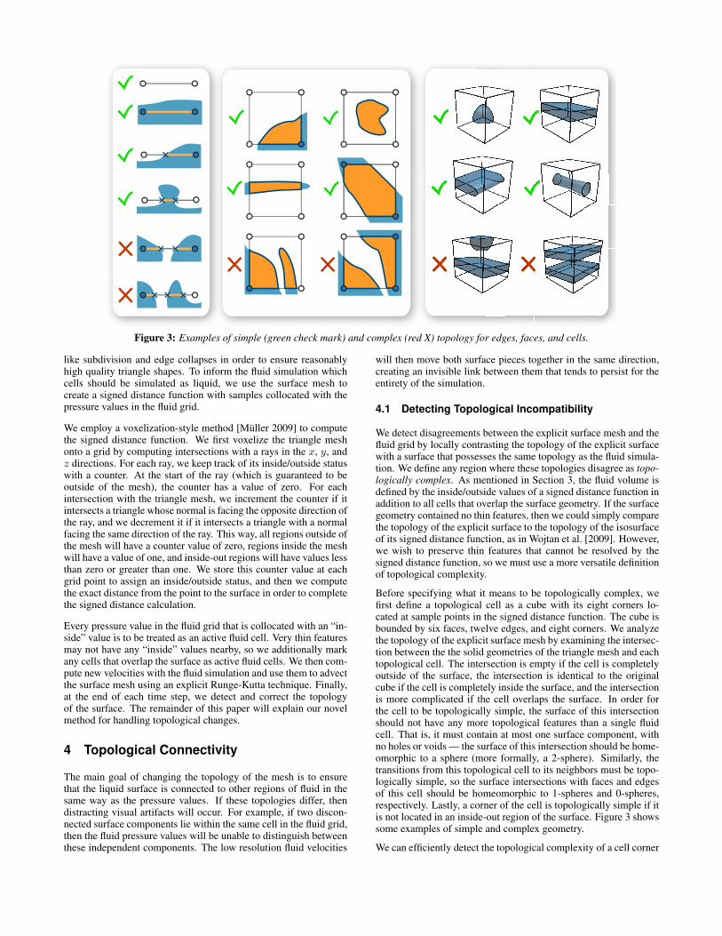
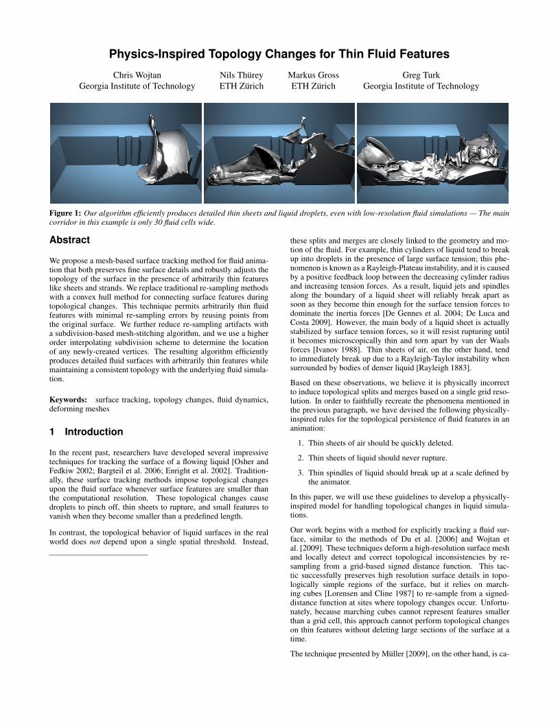
Figure 3: Examples of simple (green check mark) and complex (red X) topology for edges, faces, and cells.
like subdivision and edge collapses in order to ensure reasonablyhigh quality triangle shapes. To inform the fluid simulation whichcells should be simulated as liquid, we use the surface mesh tocreate a signed distance function with samples collocated with thepressure values in the fluid grid.
We employ a voxelization-style method [Muller 2009] to computethe signed distance function. We first voxelize the triangle meshonto a grid by computing intersections with a rays in the x, y, andz directions. For each ray, we keep track of its inside/outside statuswith a counter. At the start of the ray (which is guaranteed to beoutside of the mesh), the counter has a value of zero. For eachintersection with the triangle mesh, we increment the counter if itintersects a triangle whose normal is facing the opposite direction ofthe ray, and we decrement it if it intersects a triangle with a normalfacing the same direction of the ray. This way, all regions outside ofthe mesh will have a counter value of zero, regions inside the meshwill have a value of one, and inside-out regions will have values lessthan zero or greater than one. We store this counter value at eachgrid point to assign an inside/outside status, and then we computethe exact distance from the point to the surface in order to completethe signed distance calculation.
Every pressure value in the fluid grid that is collocated with an “in-side” value is to be treated as an active fluid cell. Very thin featuresmay not have any “inside” values nearby, so we additionally markany cells that overlap the surface as active fluid cells. We then com-pute new velocities with the fluid simulation and use them to advectthe surface mesh using an explicit Runge-Kutta technique. Finally,at the end of each time step, we detect and correct the topologyof the surface. The remainder of this paper will explain our novelmethod for handling topological changes.
4 Topological Connectivity
The main goal of changing the topology of the mesh is to ensurethat the liquid surface is connected to other regions of fluid in thesame way as the pressure values. If these topologies differ, thendistracting visual artifacts will occur. For example, if two discon-nected surface components lie within the same cell in the fluid grid,then the fluid pressure values will be unable to distinguish betweenthese independent components. The low resolution fluid velocities
will then move both surface pieces together in the same direction,creating an invisible link between them that tends to persist for theentirety of the simulation.
4.1 Detecting Topological Incompatibility
We detect disagreements between the explicit surface mesh and thefluid grid by locally contrasting the topology of the explicit surfacewith a surface that possesses the same topology as the fluid simula-tion. We define any region where these topologies disagree as topo-logically complex. As mentioned in Section 3, the fluid volume isdefined by the inside/outside values of a signed distance function inaddition to all cells that overlap the surface geometry. If the surfacegeometry contained no thin features, then we could simply comparethe topology of the explicit surface to the topology of the isosurfaceof its signed distance function, as in Wojtan et al. [2009]. However,we wish to preserve thin features that cannot be resolved by thesigned distance function, so we must use a more versatile definitionof topological complexity.
Before specifying what it means to be topologically complex, wefirst define a topological cell as a cube with its eight corners lo-cated at sample points in the signed distance function. The cube isbounded by six faces, twelve edges, and eight corners. We analyzethe topology of the explicit surface mesh by examining the intersec-tion between the the solid geometries of the triangle mesh and eachtopological cell. The intersection is empty if the cell is completelyoutside of the surface, the intersection is identical to the originalcube if the cell is completely inside the surface, and the intersectionis more complicated if the cell overlaps the surface. In order forthe cell to be topologically simple, the surface of this intersectionshould not have any more topological features than a single fluidcell. That is, it must contain at most one surface component, withno holes or voids — the surface of this intersection should be home-omorphic to a sphere (more formally, a 2-sphere). Similarly, thetransitions from this topological cell to its neighbors must be topo-logically simple, so the surface intersections with faces and edgesof this cell should be homeomorphic to 1-spheres and 0-spheres,respectively. Lastly, a corner of the cell is topologically simple if itis not located in an inside-out region of the surface. Figure 3 showssome examples of simple and complex geometry.
We can efficiently detect the topological complexity of a cell corner

Figure 4: Two bunnies splatter into each other, producing a thin liquid sheet that merges with the pool of water below.
by checking its counter from the signed distance function calcula-tion in Section 3 (the counter of a simple corner must be eitherzero or one, otherwise it means the surface is inside out or self-intersecting). Next, we determine the complexity of a cell edge bycounting the number and orientation of its intersections with trian-gles in the surface mesh and comparing the result with a single linesegment (0-sphere). If there are too many components, or if thesurface is oriented the wrong way at any of the intersection points,then the edge is complex. This step is performed at the same time asthe complex corner test (during the creation of the signed distancefield). We can check the validity of a face by computing its inter-section with the mesh and counting the number of components, andwe can test the topological status of a cell by similarly countingconnected components and ensuring that the Euler characteristicdetects no holes.
The complex corner test samples the signed distance function atseveral regularly-spaced sample points, and it is guaranteed to iden-tify any self-intersections larger than the grid spacing. This test willcatch any topological flaws that are well-resolved in the x, y, andz dimensions, just like marching cubes will faithfully reproduce asurface as long as there are no features smaller than the grid size.The complex edge test checks all of the edges in the grid, so it isguaranteed to identify any topological flaws that are well-resolvedin at least two dimensions. This means that self-intersections andpockets of air that look like thin sheets will be identified by thecomplex edge test. This test can also catch thin spindles and voidsif they happen to intersect one of the grid edges. The complex facetest checks for intersections with all faces in the grid, so it is guar-anteed to catch topological flaws that look like thin spindles (whichspan more than one cell in a single dimension, but are very thin inthe other two). However, the complex face test cannot catch topo-logical flaws smaller than a single grid cell unless they happen tointersect the face. Finally, the complex cell test is guaranteed toidentify all topological flaws, because it checks within every cell.
In practice, such topological problems smaller than a grid cell donot exist, because we start with a well-resolved surface and then
a) b) c)
Figure 5: Given a surface with complex topology (a), methodsbased on marching cubes-style lookup tables will ignore interiorvertices (b), while our method preserves many of the original de-tails (c).
smoothly deform it according to a low resolution fluid velocityfield. This means that large features morph into small featuresthrough a gradual process, by first becoming thin sheets and thenthin spindles. Because topological inconsistencies are caught bylower-dimensional complexity tests before they have time to shrinksmaller than a grid cell, we have not found it necessary to performthe full complex cell test. Complex face tests are mostly redun-dant for our purposes as well, because perturbations from the fluidvelocity tend to force thin structures to intersect cell edges — thecomplex edge and complex corner tests tend to quickly catch allproblems. As a result, we have found it practical to bypass the test-ing of any cells and faces unless we specifically have to guaranteevalid topology in a particular region.
After a complex cell is detected, we will soon replace its intersect-ing surface with a similar surface that is topologically simple. Be-cause this cell shares its boundaries with other cells that may nothave been classified as topologically complex, we have to specifi-cally guarantee that its faces are topologically simple. In this case,we count the face components and pass complexity information toneighboring cells, similar to the complex cell propagation strategyof Wojtan et al. [2009]. To summarize the frequency of topologi-cal tests in our implementation: we exhaustively test every cornerand edge in the signed distance grid, we never check cells, and weonly check faces when it is absolutely necessary to ensure simpleconnectivity between a complex cell and its topologically simpleneighbors.
4.2 Local Topological Repair
After deciding that a cell has complex topology, we must replacethe surface/cube intersection in that cell with a new one. We requirethat this new intersection surface meets two constraints: it shouldbe topologically simple, and it should preserve the connectivity ofthe original surface. In addition, because each vertex of the originalsurface represents a valuable piece of Lagrangian simulation data,we also desire that the new surface preserves as many of the originalsurface vertices as possible.
According to our definition, a sphere is topologically simple. Con-sequently, a straightforward strategy for reducing the topologicalcomplexity of a surface/cube intersection is to wrap a single sur-face around all of the original surface components until it is home-omorphic to a sphere. Fortunately, this operation can be performedefficiently by replacing the original surface/cube intersection withits convex hull. If the input surface intersected the cell boundary,then the convex hull preserves this connectivity. Furthermore, theconvex hull’s intersections with faces and edges are lower dimen-sional convex hulls, so they are also topologically simple. In addi-
a) b) c) d)
Figure 6: Given a triangle mesh and topological cell (a), we ex-amine the intersection between the the solid geometries of the meshand the cell (b). If the intersection has complex topology, we re-place it with its convex hull (c). Finally, we remove facets belongingto the boundary of the cell and reconnect the surface (d). Note thatthe cell below this one will also be re-sampled, because the bottomedge in (a) is topologically complex.
tion, all of the vertices on this convex hull are preserved from theinput surface, so we reduce re-sampling errors during this process,as illustrated in Figure 5.
In practice, we use the qhull library [Barber and Huhdanpaa 1995]to compute the convex hull of the following points: all originalsurface vertices that lie within that cell, the vertices created by in-tersecting the original mesh with the edges and faces of the cell(described in Section 5), and all “inside” corners of the cell. Fi-nally, because the convex hull represents the intersection betweena cube and the new surface, we extract the final surface by deletingany facets that are co-planar with the cell boundary. See Figure 6for an example.
This strategy of reducing complex surface regions to topologicalspheres has physical implications when used in a fluid simulation:(1) thin sheets of air will be detected as topologically complexand destroyed, and (2) thin sheets and strands of liquid will persistthroughout the simulation. Thus, we have already satisfied two outof the three physically-based topological rules laid out in Section1, and we will explain how to allow the breakup of thin spindles inSection 4.3.
4.3 Topological Control
The method presented in Section 4.2 will preserve all thin sheetsand spindles unless there are significant self-intersections. In casewe desire different behaviors, we can modify the presented algo-rithm by altering our definition of topological complexity. For ex-ample, we could force the breakup of thin liquid spindles by declar-ing that a cell face is complex when the surface intersects the facebut not its bounding edges. To create a re-sampled surface thatrespects this altered definition of topological complexity, we cansimply remove any vertices on that face from the input to the con-vex hull algorithm. We can similarly remove many vertices fromthe convex hull input if we want to speed up computation time, al-though we did not find this optimization necessary.
An alternative to modifying the definition of topological complexityis to manually perform topological changes to the surface throughexplicit mesh surgery. We have found that this approach for cut-ting thin spindles of liquid produces better results than the methodoutlined in the preceding paragraph, because explicit cutting allowsus to have tighter control over the thickness of the surface beforethe separation. We can detect thin spindles of liquid while perform-ing the local surface maintenance operations (Section 3), when weflag edges that will produce non-manifold geometry if collapsed.Of these non-manifold cases, we can easily identify any thin spin-dles by their triangular cross-section. To perform the mesh surgery,we cut the mesh at the triangular cross-section, seal each end witha new triangle, and perturb the two new strands away from eachother by a small offset. A similar operation is explained in detail byLachaud et al. [2003].
As explained in Section 1, thin spindles of liquid consistentlylead to topological changes in real-world liquids. Due to asurface-tension-based Rayleigh-Plateau instability, the liquid spin-dle rapidly collapses until it is infinitely thin and then breaks intwo. Our explicit cutting operation precisely mimics this behaviorin the discrete setting by separating the thinnest possible unit of adiscrete surface. This cutting method is also quite efficient — it isdetected for free during standard surface maintenance operations,and it requires about as much work as a single edge collapse.
Both of these proposed methods give us control over the breakup ofthin liquid spindles, satisfying our final physically-based topologyrequirement from Section 1. Using these proposed topology modi-fications, the animator can specify either the topological grid lengthor the maximum allowed edge length in order to force the breakupof thin liquid spindles.
5 Sewing Meshes Together
Before re-sampling the surfaces in Section 4.2, we subdivide theoriginal surface mesh so that it perfectly lines up with the bound-aries of each complex cell. We first subdivide triangles where theyintersect the boundary edge of a complex cell, and then we subdi-vide edges where they intersect the boundary faces of a complexcell, following the algorithm of Du et al. [2006]. Next, we discardthe original surface within the complex cells and replace them withtopologically simple convex hull surfaces from Section 4.2. Finally,we must stitch the surfaces together along the cell boundaries.
5.1 Subdivision Stitching
One possible mesh-stitching strategy is to progressively collapsetriangles on both sides of the cell boundary until the detailed in-tersection between the surface and cell face is reduced to a linesegment. However, such a strategy deletes important Lagrangiansurface samples and can lead to robustness problems [Wojtan et al.2009]. Instead of altering the original surface and destroying its La-grangian data, we choose to only alter the new re-sampled surface.
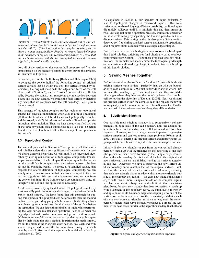
Initially, if the new triangles output from the convex hull alreadyperfectly match up with the triangles on the other side of the face(the piecewise linear curve formed by the triangle edges coinci-dent with each boundary face is identical for both the original andnew surfaces), then we are finished sewing the surfaces togetherat this face. Otherwise, we have to subdivide the new surface un-til its boundary curve matches that of the original surface. First,we limit the number of cases that we need to address by ensuringthat each new triangle shares an edge with at most one triangle out-side of the complex cell region — for each new triangle that sharesedges with two or more triangles outside of the complex region,we place a vertex at its barycenter and split it into three new trian-gles. Next, for each new triangle that does not perfectly match upwith a segment of the boundary curve, we subdivide it in two byadding a point on its boundary edge and snapping it to one of thevertices on the boundary curve. We then recursively subdivide eachof these newly-created triangles in the same way until the curvesperfectly match (each curve eventually reduces to a single line seg-ment in the base case), similar to the algorithm used by Bischoff and
Figure 7: Before and after sewing the meshes together.
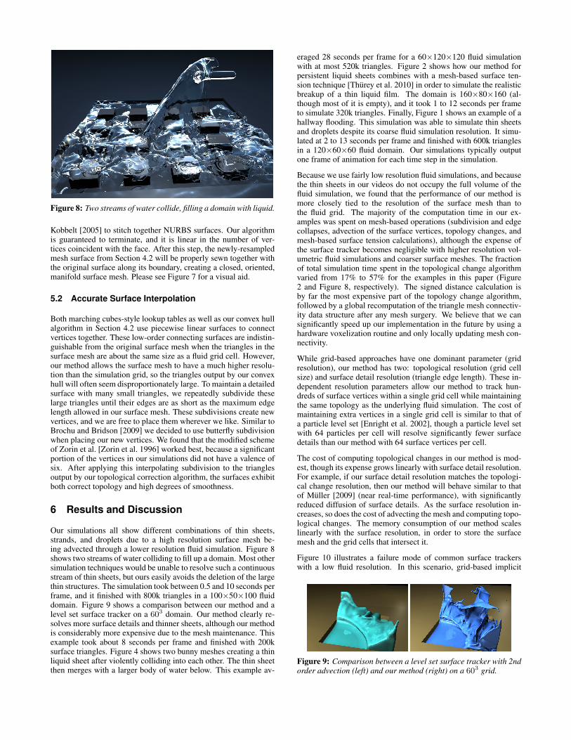
Figure 8: Two streams of water collide, filling a domain with liquid.
Kobbelt [2005] to stitch together NURBS surfaces. Our algorithmis guaranteed to terminate, and it is linear in the number of ver-tices coincident with the face. After this step, the newly-resampledmesh surface from Section 4.2 will be properly sewn together withthe original surface along its boundary, creating a closed, oriented,manifold surface mesh. Please see Figure 7 for a visual aid.
5.2 Accurate Surface Interpolation
Both marching cubes-style lookup tables as well as our convex hullalgorithm in Section 4.2 use piecewise linear surfaces to connectvertices together. These low-order connecting surfaces are indistin-guishable from the original surface mesh when the triangles in thesurface mesh are about the same size as a fluid grid cell. However,our method allows the surface mesh to have a much higher resolu-tion than the simulation grid, so the triangles output by our convexhull will often seem disproportionately large. To maintain a detailedsurface with many small triangles, we repeatedly subdivide theselarge triangles until their edges are as short as the maximum edgelength allowed in our surface mesh. These subdivisions create newvertices, and we are free to place them wherever we like. Similar toBrochu and Bridson [2009] we decided to use butterfly subdivisionwhen placing our new vertices. We found that the modified schemeof Zorin et al. [Zorin et al. 1996] worked best, because a significantportion of the vertices in our simulations did not have a valence ofsix. After applying this interpolating subdivision to the trianglesoutput by our topological correction algorithm, the surfaces exhibitboth correct topology and high degrees of smoothness.
6 Results and Discussion
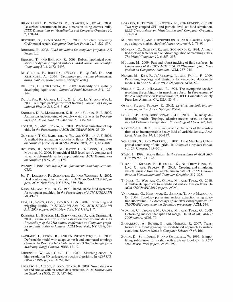
Our simulations all show different combinations of thin sheets,strands, and droplets due to a high resolution surface mesh be-ing advected through a lower resolution fluid simulation. Figure 8shows two streams of water colliding to fill up a domain. Most othersimulation techniques would be unable to resolve such a continuousstream of thin sheets, but ours easily avoids the deletion of the largethin structures. The simulation took between 0.5 and 10 seconds perframe, and it finished with 800k triangles in a 100×50×100 fluiddomain. Figure 9 shows a comparison between our method and alevel set surface tracker on a 603 domain. Our method clearly re-solves more surface details and thinner sheets, although our methodis considerably more expensive due to the mesh maintenance. Thisexample took about 8 seconds per frame and finished with 200ksurface triangles. Figure 4 shows two bunny meshes creating a thinliquid sheet after violently colliding into each other. The thin sheetthen merges with a larger body of water below. This example av-
eraged 28 seconds per frame for a 60×120×120 fluid simulationwith at most 520k triangles. Figure 2 shows how our method forpersistent liquid sheets combines with a mesh-based surface ten-sion technique [Thurey et al. 2010] in order to simulate the realisticbreakup of a thin liquid film. The domain is 160×80×160 (al-though most of it is empty), and it took 1 to 12 seconds per frameto simulate 320k triangles. Finally, Figure 1 shows an example of ahallway flooding. This simulation was able to simulate thin sheetsand droplets despite its coarse fluid simulation resolution. It simu-lated at 2 to 13 seconds per frame and finished with 600k trianglesin a 120×60×60 fluid domain. Our simulations typically outputone frame of animation for each time step in the simulation.
Because we use fairly low resolution fluid simulations, and becausethe thin sheets in our videos do not occupy the full volume of thefluid simulation, we found that the performance of our method ismore closely tied to the resolution of the surface mesh than tothe fluid grid. The majority of the computation time in our ex-amples was spent on mesh-based operations (subdivision and edgecollapses, advection of the surface vertices, topology changes, andmesh-based surface tension calculations), although the expense ofthe surface tracker becomes negligible with higher resolution vol-umetric fluid simulations and coarser surface meshes. The fractionof total simulation time spent in the topological change algorithmvaried from 17% to 57% for the examples in this paper (Figure2 and Figure 8, respectively). The signed distance calculation isby far the most expensive part of the topology change algorithm,followed by a global recomputation of the triangle mesh connectiv-ity data structure after any mesh surgery. We believe that we cansignificantly speed up our implementation in the future by using ahardware voxelization routine and only locally updating mesh con-nectivity.
While grid-based approaches have one dominant parameter (gridresolution), our method has two: topological resolution (grid cellsize) and surface detail resolution (triangle edge length). These in-dependent resolution parameters allow our method to track hun-dreds of surface vertices within a single grid cell while maintainingthe same topology as the underlying fluid simulation. The cost ofmaintaining extra vertices in a single grid cell is similar to that ofa particle level set [Enright et al. 2002], though a particle level setwith 64 particles per cell will resolve significantly fewer surfacedetails than our method with 64 surface vertices per cell.
The cost of computing topological changes in our method is mod-est, though its expense grows linearly with surface detail resolution.For example, if our surface detail resolution matches the topologi-cal change resolution, then our method will behave similar to thatof Muller [2009] (near real-time performance), with significantlyreduced diffusion of surface details. As the surface resolution in-creases, so does the cost of advecting the mesh and computing topo-logical changes. The memory consumption of our method scaleslinearly with the surface resolution, in order to store the surfacemesh and the grid cells that intersect it.
Figure 10 illustrates a failure mode of common surface trackerswith a low fluid resolution. In this scenario, grid-based implicit
Figure 9: Comparison between a level set surface tracker with 2ndorder advection (left) and our method (right) on a 603 grid.

Figure 10: In this example, the level set method (left) deletes thin sheets before they even touch the ground. The method of Wojtan et al. 2009(middle) re-samples the surface from a grid during topological changes, so it cannot merge together multiple thin sheets without deletinglarge portions of the surface. Our method (right) merges together thin sheets without rampant thin feature deletion.
surface trackers (level sets, particle level sets, and semi-Lagrangiancontouring, for example) limit the surface detail to that of thegrid resolution, which causes catastrophic deletion of thin features.Naively increasing the surface resolution can cause the topology ofthe fluid simulation to differ from that of the surface tracker. Suchmismatched topologies can lead to artifacts such as several surfacecomponents floating within a single fluid cell, as well as an unphys-ical breakup of thin sheets. Artificially diffusing the level set [Kimet al. 2009] can force these floating components to merge together,at the expense of limiting surface detail, losing volume, and punch-ing holes in thin sheets. Our method is the only surface tracker todate that can showcase arbitrarily high levels of surface detail with-out sacrificing topological agreement between the surface and thefluid.
Although we did not use exact arithmetic to compute the topolog-ical details of our algorithm, we did take precautions to make itrobust in the face of numerical precision errors. In the event thata numerical error causes impossible topology or leads to difficultysewing together the mesh, we mark all cells near the error as topo-logically complex and re-sample the geometry within them.
We tried to preserve as much Lagrangian surface information aspossible throughout the surface tracking process, and our topolog-ical constraints allow us to advect surface meshes that are muchhigher resolution than the fluid velocity field. Consequently, wecan animate highly detailed surfaces through time without losingsurface features to a re-sampling process. However, this retentionof high frequency details may not always be desirable. Some pos-sible ways to smooth out extra details are with geometric smooth-ing or simulated surface tension. In addition, our topological cor-rections will often replace high-frequency surface details with aless detailed surface whenever they detect complex geometry. Thisreplacement can lead to noticeable temporal discontinuities whensimulating with an extremely low resolution fluid simulation grid.
Because our topological algorithm primarily merges fluid regionstogether and rarely splits things apart, the liquid in our simulationstends to exhibit an overall gain in volume, especially after long,violently splashing simulations with many topological merges. Thisis the opposite of the common volume-loss problem with level set-style surface trackers, and the amount of volume gain is closely tiedto the coarseness of the fluid grid.
Nevertheless, we intentionally used low-resolution fluid simula-tions in many of our examples to show the advantage of separat-ing the visible surface resolution from the resolution of the velocityfield. The hallway in Figure 1, for example, is only 30 grid cellswide. Despite the coarse physics, our method is able to developmany high resolution surface details while still matching the topol-ogy of the low resolution fluid simulation. The additional detailgained from separating the fluid simulation from its surface allows
us to avoid simulating expensive high resolution physics when onlya highly detailed surface is necessary.
7 Conclusion and Future Work
We have presented a mesh-based surface tracking method for fluidanimation that both preserves fine surface details and robustly ad-justs the topology of the surface in the presence of thin features likesheets and strands. Our local convex-hull-based method for correct-ing the topology of surfaces enforces the overall topological behav-ior of real-world liquids, and we can achieve arbitrarily thin sheetsand strands without re-sampling important Lagrangian surface de-tails. We further reduce re-sampling artifacts with a subdivision-based mesh-stitching algorithm, and we use a higher order interpo-lating subdivision scheme to determine the location of any newly-created vertices. We have shown how our method can be appliedto efficiently produce high-quality fluid surface animations, evenwhen coupled to under-resolved fluid simulations.
In the future, we would like to look into mesh-based methods forcreating sub-grid scale physical behaviors. In addition to using amesh-based surface tension method [Thurey et al. 2010], we believethat other surface-focused approximations to forces in the Navier-Stokes equations like the vortex sheet method of Kim et al. [2009]could yield highly detailed simulations without the expense of run-ning a full fluid simulation. Lastly, one potentially fruitful area offuture work is to investigate the possibility of topologically sepa-rating fluid surfaces instead of merging them together, as done forelastic models by Teran et al. [2005] and Nesme et al. [2009].
Acknowledgements
We would like to thank Tobias Pfaff for editing our supplementalvideo and Thomas Oskam for creating some of the figures in thispaper. The first author was funded through the NSF grants CCF-0811485 and CCF-0625264.
References
BARBER, C., AND HUHDANPAA, H., 1995. Qhull, Softwarepack-age.
BARGTEIL, A., GOKTEKIN, T., O’BRIEN, J., AND STRAIN, J.2006. A semi-Lagrangian contouring method for fluid simula-tion. ACM Transactions on Graphics (TOG) 25, 1, 38.
BHANIRAMKA, P., WENGER, R., AND CRAWFIS, R. 2000. Iso-surfacing in higher dimensions. In Proceedings of the conferenceon Visualization’00, IEEE Computer Society Press Los Alami-tos, CA, USA, 267–273.
BHANIRAMKA, P., WENGER, R., CRAWFIS, R., ET AL. 2004.Isosurface construction in any dimension using convex hulls.IEEE Transactions on Visualization and Computer Graphics 10,2, 130–141.
BISCHOFF, S., AND KOBBELT, L. 2005. Structure preservingCAD model repair. Computer Graphics Forum 24, 3, 527–536.
BRIDSON, R. 2008. Fluid simulation for computer graphics. AKPeters Ltd.
BROCHU, T., AND BRIDSON, R. 2009. Robust topological oper-ations for dynamic explicit surfaces. SIAM Journal on ScientificComputing 31, 4, 2472–2493.
DE GENNES, P., BROCHARD-WYART, F., QUERE, D., ANDREISINGER, A. 2004. Capillarity and wetting phenomena:drops, bubbles, pearls, waves. Springer Verlag.
DE LUCA, L., AND COSTA, M. 2009. Instability of a spatiallydeveloping liquid sheet. Journal of Fluid Mechanics 331, 127–144.
DU, J., FIX, B., GLIMM, J., JIA, X., LI, X., LI, Y., AND WU, L.2006. A simple package for front tracking. Journal of Compu-tational Physics 213, 2, 613–628.
ENRIGHT, D. P., MARSCHNER, S. R., AND FEDKIW, R. P. 2002.Animation and rendering of complex water surfaces. In Proceed-ings of ACM SIGGRAPH 2002, vol. 21, 736–744.
FOSTER, N., AND FEDKIW, R. 2001. Practical animation of liq-uids. In the Proceedings of ACM SIGGRAPH 2001, 23–30.
GOKTEKIN, T. G., BARGTEIL, A. W., AND O’BRIEN, J. F. 2004.A method for animating viscoelastic fluids. ACM Transactionson Graphics (Proc. of ACM SIGGRAPH 2004) 23, 3, 463–468.
HOUSTON, B., NIELSEN, M., BATTY, C., NILSSON, O., ANDMUSETH, K. 2006. Hierarchical RLE level set: A compact andversatile deformable surface representation. ACM Transactionson Graphics (TOG) 25, 1, 175.
IVANOV, I. 1988. Thin liquid films: fundamentals and applications.CRC.
JU, T., LOSASSO, F., SCHAEFER, S., AND WARREN, J. 2002.Dual contouring of hermite data. In ACM SIGGRAPH 2002 pa-pers, ACM New York, NY, USA, 339–346.
KASS, M., AND MILLER, G. 1990. Rapid, stable fluid dynamicsfor computer graphics. In the Proceedings of ACM SIGGRAPH90, 49–57.
KIM, D., SONG, O.-Y., AND KO, H.-S. 2009. Stretching andwiggling liquids. In SIGGRAPH Asia ’09: ACM SIGGRAPHAsia 2009 papers, ACM, New York, NY, USA, 1–7.
KOBBELT, L., BOTSCH, M., SCHWANECKE, U., AND SEIDEL, H.2001. Feature sensitive surface extraction from volume data. InProceedings of the 28th annual conference on Computer graph-ics and interactive techniques, ACM New York, NY, USA, 57–66.
LACHAUD, J., TATON, B., AND EN INFORMATIQUE, L. 2003.Deformable model with adaptive mesh and automated topologychanges. In Proc. 4th Int. Conference on 3D Digital Imaging andModeling, Banff, Canada, IEEE, 12–19.
LORENSEN, W., AND CLINE, H. 1987. Marching cubes: Ahigh resolution 3D surface construction algorithm. In ACM SIG-GRAPH 1987 papers, ACM, 169.
LOSASSO, F., GIBOU, F., AND FEDKIW, R. 2004. Simulating wa-ter and smoke with an octree data structure. ACM Transactionson Graphics (TOG) 23, 3, 457–462.
LOSASSO, F., TALTON, J., KWATRA, N., AND FEDKIW, R. 2008.Two-way coupled SPH and particle level set fluid simulation.IEEE Transactions on Visualization and Computer Graphics,797–804.
MCINERNEY, T., AND TERZOPOULOS, D. 2000. T-snakes: Topol-ogy adaptive snakes. Medical Image Analysis 4, 2, 73–91.
MONTANI, C., SCATENI, R., AND SCOPIGNO, R. 1994. A modi-fied look-up table for implicit disambiguation of marching cubes.The Visual Computer 10, 6, 353–355.
MULLER, M. 2009. Fast and robust tracking of fluid surfaces. InProceedings of the 2009 ACM SIGGRAPH/Eurographics Sym-posium on Computer Animation, ACM, 237–245.
NESME, M., KRY, P., JERABKOVA, L., AND FAURE, F. 2009.Preserving topology and elasticity for embedded deformablemodels. In ACM SIGGRAPH 2009 papers, ACM, 52.
NIELSON, G., AND HAMANN, B. 1991. The asymptotic decider:resolving the ambiguity in marching cubes. In Proceedings ofthe 2nd conference on Visualization’91, IEEE Computer SocietyPress Los Alamitos, CA, USA, 83–91.
OSHER, S., AND FEDKIW, R. 2002. Level set methods and dy-namic implicit surfaces. Springer Verlag.
PONS, J.-P., AND BOISSONNAT, J.-D. 2007. Delaunay de-formable models: Topology-adaptive meshes based on the re-stricted Delaunay triangulation. Proceedings of CVPR ’07, 1–8.
RAYLEIGH, L. 1883. Investigation of the character of the equilib-rium of an incompressible heavy fluid of variable density. Proc.Lond. Math. Soc 14, 1, 170–177.
SCHAEFER, S., AND WARREN, J. 2005. Dual Marching Cubes:primal contouring of dual grids. In Computer Graphics Forum,vol. 24, Citeseer, 195–201.
STAM, J. 1999. Stable fluids. In the Proceedings of ACM SIG-GRAPH 99, 121–128.
TERAN, J., SIFAKIS, E., BLEMKER, S., NG-THOW-HING, V.,LAU, C., AND FEDKIW, R. 2005. Creating and simulatingskeletal muscle from the visible human data set. IEEE Transac-tions on Visualization and Computer Graphics, 317–328.
THUREY, N., WOJTAN, C., GROSS, M., AND TURK, G. 2010.A multiscale approach to mesh-based surface tension flows. InACM SIGGRAPH 2010 papers, ACM.
VARADHAN, G., KRISHNAN, S., SRIRAM, T., AND MANOCHA,D. 2004. Topology preserving surface extraction using adap-tive subdivision. In Proceedings of the 2004 Eurographics/ACMSIGGRAPH symposium on Geometry processing, ACM, 244.
WOJTAN, C., THUREY, N., GROSS, M., AND TURK, G. 2009.Deforming meshes that split and merge. In ACM SIGGRAPH2009 papers, ACM, 76.
ZAHARESCU, A., BOYER, E., AND HORAUD, R. 2007. Trans-formesh: a topology-adaptive mesh-based approach to surfaceevolution. Lecture Notes in Computer Science 4844, 166.
ZORIN, D., SCHRODER, P., AND SWELDENS, W. 1996. Interpo-lating subdivision for meshes with arbitrary topology. In ACMSIGGRAPH 1996 papers, ACM, 192.


![Matching Fluid Simulation Elements to Surface Geometry …batty/papers/Brochu10.pdf · Matching Fluid Simulation Elements to Surface Geometry and Topology ... [Computer Graphics]:](https://static.fdocuments.in/doc/165x107/5b5d34ee7f8b9a68368e5113/matching-fluid-simulation-elements-to-surface-geometry-battypapersbrochu10pdf.jpg)