Physics Fundamentals: Laser Diode Characteristics · LaserLinesBasics.indd • Page 14 Kieler Str....
21
LaserLinesBasics.indd • Page 14 Kieler Str. 212, 22525 Hamburg, Germany • Tel: +49 40 85 39 97-0 • Fax: +49 40 85 39 97-79 • [email protected] • www.SuKHamburg.com 14 01-2016 E Physics Fundamentals Laser Diodes Physics Fundamentals: Laser Diode Characteristics Laser Diodes are semiconductor lasers and are available in many different shapes and sizes with laser powers ranging from a few mW to hundreds of watts. The emitted wavelength depends mainly on the semiconductor material of the laser diode cavity and laser diodes are produced to cover the full visible spectrum from blue to red, and even beyond, with some emitting in the infrared. The laser diodes distributed by Schäfter+Kirchhoff cover the whole wavelength range from 370 nm to 2300 nm. The microscopic cross-section of the laser diode active area of 1 x 3 μm results in emitted radiation that is divergent. Most laser diodes have a cone of divergent radiation with an elliptical cross- section and an approximately Gaussian intensity distribution. The ellipticity can be overcome with the help of anamorphic optics. Some diodes (e.g. VCSEL or Circular Laser) are designed to produce a circular beam profile. Divergence and Polarization 1/e² FWHM T__ FWHM TA TAFWHM The polarization of the emitted radiation is linear and is parallel to the active area of the diode. The degree of polarization varies with the diode current and is lowest at the threshold. The emitted spectrum is in- fluenced by the diode temperature and diode current, as well as the geometry of the laser cavity. The front face and the end face serve as a Fabry-Perot cavity allowing multiple longitudinal modes. When operated just over the threshold, the diodes have a wavelength spectrum with equidistant peaks (longitudinally multimode). On increasing the diode current (to produce a higher power output), one of the longitudinal modes is usually favored and the diode emits in (longitudinally) singlemode. Unfortunately, the gain profile and the refractive index of the semiconductor material are Wavelength Op (nm) Optical Power Output Dependence of Wavelength 830 828 826 Po = 10mW Po = 3mW Po = 40mW 836 832 828 Wavelength vs. Temperature Case temperature TC (C°) nm 20 30 40 50 Po = 30mW Temperature and Power Dependence temperature dependent and, so, other longitudinal modes can be amplified and the output wavelength changes rapidly, by up to a few nanometers, resulting in mode hopping. For a non-stabilized singlemode diode, mode hopping occurs stochastically and the emitted wavelength and output power can change erratically by as much as 3%. For a temperature range of 20 to 30°C, the center wavelength can drift by 2.5–3 nm (GaAs). Since changing the diode current changes the diode temperature, the current/power output dependence of the laser diode is only nominal. When the laser power is increased from the threshold up to the nominal power then the wavelength increases by 2–4 nm. The particular application determ- ines whether a long coherence Lc (here given for a Gaussian spectrum) or a short coherence is desirable. Non-stabilized singlemode lasers with stochastic changes of the wavelength also exhibit stochastic changes in coherence behavior. Superluminescent diodes use incoherent spontaneous emission to provide short coherence. For Coherence L c FWHM = Δ λ λ 2 'OFWHM interferometry or spectroscopy, a long (or sufficient) coherence is essential, a feature of DFB, DBR VCSEL diodes with integrated or external thermo-electric cooling (TEC). The emitted wavelength can be kept constant in a number of ways. External temperature control is possible using integrated or external Peltier elements and temperature sensors (see 48TE SOT-...). Most laser diodes also have an integrated monitor photodiode, providing feedback for control of the laser power. The use of DFB (distributed feedback) or DBR diodes Wavelength Constancy Non-stabilized singlemode diode Narrow tunable DFB spectrum (distributed Bragg reflector) with their spectrally very narrow lines can be advantageous. With the help of a grid structure, only one longitudinal Fabry-Perot mode is amplified (stable singlemode) and mode hopping is suppressed. VCSEL diodes use DBR structures to produce very narrow lines. The temperature dependence remains, however, and a constant wavelength can only be provided by using an integrated or external temperature control system with integrated monitoring photodiode. Laser diodes are very sensitive, especially when exposed to an electrostatic discharge. Surges in the current or voltage can damage a diode severely, making extremely stable power sources a necessity. The life expectancy of the diode is increased at lower diode temperatures and power outputs, making it very important to operate the diode below its maximum current. Faraday Isolators (48FI-5-...) can effectively prevent back-reflection into the diode 1 . Back-reflections can cause mode hopping 2 and instabilities in the diode wavelength as well as the power output that, in turn, result in faster degradation of the performance and to disturbance of the polarization. 1 2 Lifetime and Low Noise Operation Faraday isolator prevents back- reflection and the diode spectrum is undisturbed Mode hopping from destabilization of the diode by back-reflections The non-uniform gain profile within the active layer of the laser diode means that some laser diodes show astigmatism. Here, the laser radiation emitted parallel and perpendicular to the active layer does not emerge from one point at the cavity end, but appears to be emerging from two different positions. The distance between Astigmatism 'As these is called the astigmatic difference 'As and is between 3–40 μm. Astigmatism can be corrected by using anamorphic optics (5AN-...).
Transcript of Physics Fundamentals: Laser Diode Characteristics · LaserLinesBasics.indd • Page 14 Kieler Str....

Lase
rLin
esB
asic
s.in
dd
• P
age
14
Kieler Str. 212, 22525 Hamburg, Germany • Tel: +49 40 85 39 97-0 • Fax: +49 40 85 39 97-79 • [email protected] • www.SuKHamburg.com
14 01-2016 E
Phy
sics
Fun
dam
enta
ls
Laser Diodes
Physics Fundamentals: Laser Diode Characteristics
Laser Diodes are semiconductor lasers and are available in many different shapes and sizes with laser powers ranging from a few mW to hundreds of watts.
The emitted wavelength depends mainly on the semiconductor material of the laser diode cavity and laser diodes are produced to cover the full visible spectrum from blue to red, and even beyond, with some emitting in the infrared.
The laser diodes distributed by Schäfter+Kirchhoff cover the whole wavelength range from 370 nm to 2300 nm.
The microscopic cross-section of the laser diode active area of 1 x 3 μm results in emitted radiation that is divergent. Most laser diodes have a cone of divergent radiation with an elliptical cross-section and an appro ximately Gaussian intensity distribution. The ellipticity can be overcome with the help of anamorphic optics.
Some diodes (e.g. VCSEL or Circular Laser) are designed to produce a circular beam profile.
Divergence and Polarization
1/e² FWHM
FWHM
FWHM
The polarization of the emitted radiation is linear and is parallel to the active area of the diode. The degree of polarization varies with the diode current and is lowest at the threshold.
The emitted spectrum is in-fluenced by the diode temperature and diode current, as well as the geometry of the laser cavity. The front face and the end face serve as a Fabry-Perot cavity allowing multiple longitudinal modes.
When operated just over the threshold, the diodes have a wavelength spectrum with equidistant peaks (longitudinally multimode). On increasing the diode current (to produce a higher power output), one of the longitudinal modes is usually favored and the diode emits in (longitudinally) singlemode.
Unfortunately, the gain profile and the refractive index of the semiconductor material are
Wavelength p (nm)
Optical Power OutputDependence of Wavelength
830828826
Po = 10mW
Po = 3mW
Po = 40mW
836
832
828
Wavelength vs. Temperature
Case temperature TC (C°)
nm
20 30 40 50
Po = 30mW
Temperature and Power Dependence
temperature dependent and, so, other longitudinal modes can be amplified and the output wavelength changes rapidly, by up to a few nanometers, resulting in mode hopping.
For a non-stabilized singlemode diode, mode hopping occurs stochastically and the emitted wavelength and output power can change erratically by as much as 3%. For a temperature range of 20 to 30°C, the center wavelength can drift by 2.5–3 nm (GaAs).
Since changing the diode current changes the diode temperature, the current/power output dependence of the laser diode is only nominal. When the laser power is increased from the threshold up to the nominal power then the wavelength increases by 2–4 nm.
The particular application determ-ines whether a long coherence Lc (here given for a Gaussian spectrum) or a short coherence is desirable. Non-stabilized singlemode lasers with stochastic changes of the wavelength also exhibit stochastic changes in coherence behavior. Superluminescent diodes use incoherent spontaneous emission to provide short coherence. For
Coherence
LcFWHM
=Δλλ
2
FWHM
interferometry or spectroscopy, a long (or sufficient) coherence is essential, a feature of DFB, DBR VCSEL diodes with integrated or external thermo-electric cooling (TEC).
The emitted wavelength can be kept constant in a number of ways. External temperature control is possible using integrated or external Peltier elements and temperature sensors (see 48TE SOT-...). Most laser diodes also have an integrated monitor photodiode, providing feedback for control of the laser power.
The use of DFB (distributed feedback) or DBR diodes
Wavelength Constancy
Non-stabilized singlemode diode
Narrow tunable DFB spectrum
(distributed Bragg reflector) with their spectrally very narrow lines can be advantageous. With the help of a grid structure, only one longitudinal Fabry-Perot mode is amplified (stable singlemode) and mode hopping is suppressed. VCSEL diodes use DBR structures to produce very narrow lines. The temperature dependence remains, however, and a constant wavelength can only be provided by using an integrated or external temperature control system with integrated monitoring photodiode.
Laser diodes are very sensitive, especially when exposed to an electrostatic discharge. Surges in the current or voltage can damage a diode severely, making extremely stable power sources a necessity. The life expectancy of the diode is increased at lower diode temperatures and power outputs, making it very important to operate the diode below its maximum current.
Faraday Isolators (48FI-5-...) can effectively prevent back-reflection into the diode 1 .
Back-reflections can cause mode hopping 2 and instabilities in the diode wavelength as well as the power output that, in turn, result in faster degradation of the performance and to disturbance of the polarization.
1
2
Lifetime and Low Noise Operation
Faraday isolator prevents back-reflection and the diode spectrum is undisturbed
Mode hopping from destabilization of the diode by back-reflections
The non-uniform gain profile within the active layer of the laser diode means that some laser diodes show astigmatism. Here, the laser radiation emitted parallel and perpendicular to the active layer does not emerge from one point at the cavity end, but appears to be emerging from two different positions. The distance between
Astigmatism
As
these is called the astigmatic difference As and is between 3–40 μm. Astigmatism can be corrected by using anamorphic optics (5AN-...).
Lase
rLin
esB
asic
s.in
dd
• P
age
15
Kieler Str. 212, 22525 Hamburg, Germany • Tel: +49 40 85 39 97-0 • Fax: +49 40 85 39 97-79 • [email protected] • www.SuKHamburg.com
1501-2016 E
Phy
sics
Fun
dam
enta
ls
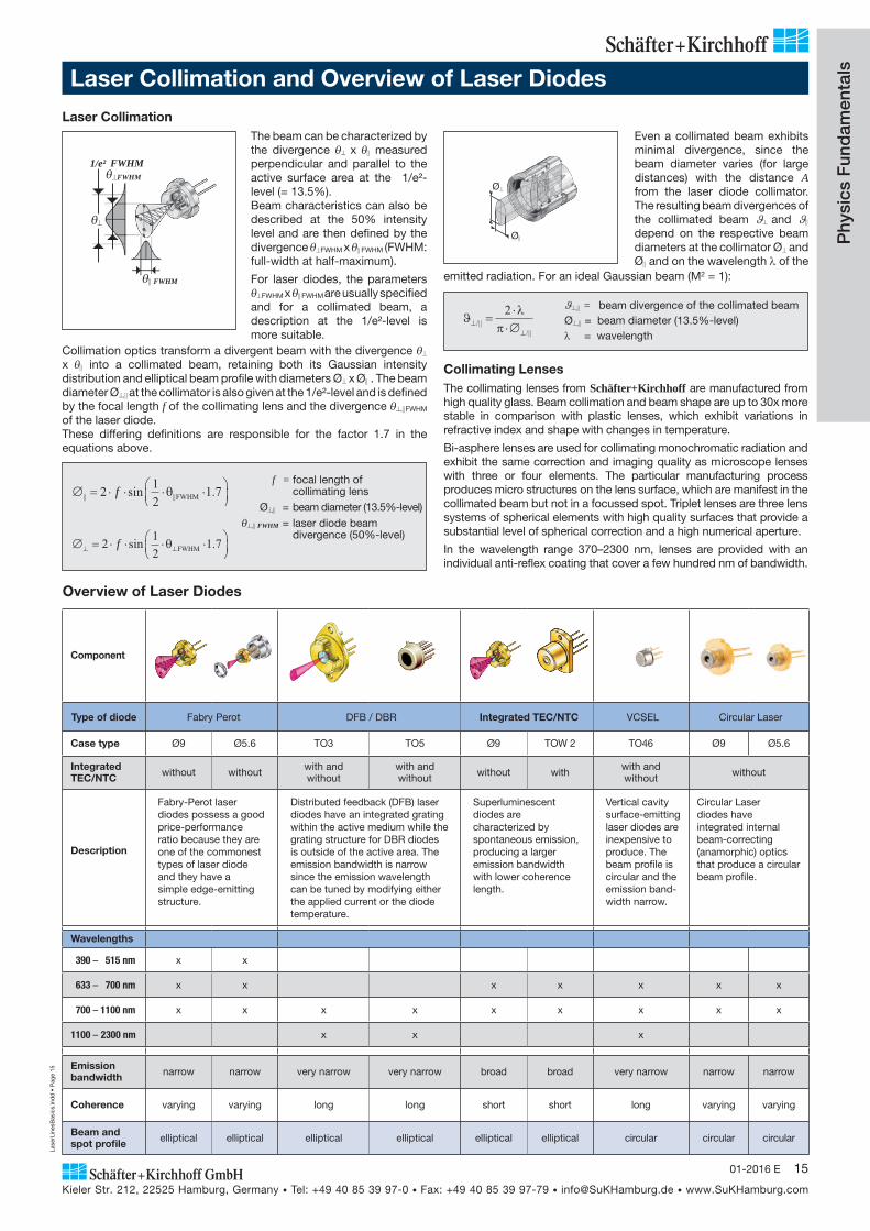
Collimating LensesThe collimating lenses from Schäfter+Kirchhoff are manufactured from high quality glass. Beam collimation and beam shape are up to 30x more stable in comparison with plastic lenses, which exhibit variations in refractive index and shape with changes in temperature.
Bi-asphere lenses are used for collimating monochromatic radiation and exhibit the same correction and imaging quality as microscope lenses with three or four elements. The particular manufacturing process produces micro structures on the lens surface, which are manifest in the collimated beam but not in a focussed spot. Triplet lenses are three lens systems of spherical elements with high quality surfaces that provide a substantial level of spherical correction and a high numerical aperture.
In the wavelength range 370–2300 nm, lenses are provided with an individual anti-reflex coating that cover a few hundred nm of bandwidth.
∅ = ⋅ ⋅ ⋅ ⋅⎛⎝⎜
⎞⎠⎟|| ||sin .2 1
21 7f θ FWHM
∅ = ⋅ ⋅ ⋅ ⋅⎛⎝⎜
⎞⎠⎟⊥ ⊥2 1
21 7f sin .θ FWHM
f = focal length of collimating lens Ø = beam diameter (13.5%-level)
FWHM = laser diode beam divergence (50%-level)
Ø
Ø
The beam can be characterized by the divergence x measured perpendicular and parallel to the active surface area at the 1/e²-level (= 13.5%). Beam characteristics can also be described at the 50% intensity level and are then defined by the divergence FWHM x FWHM (FWHM: full-width at half-maximum).
For laser diodes, the parameters FWHM x FWHM are usually specified
and for a collimated beam, a description at the 1/e²- le vel is more suitable.
Laser Collimation
1/e² FWHM
FWHM
Collimation optics transform a divergent beam with the divergence x into a collimated beam, retaining both its Gaussian intensity distribution and elliptical beam profile with diameters Ø x Ø . The beam diameter Ø at the collimator is also given at the 1/e²-level and is defined by the focal length f of the collimating lens and the divergence FWHM
of the laser diode.These differing definitions are responsible for the factor 1.7 in the equations above.
Even a collimated beam exhibits minimal divergence, since the beam diameter varies (for large distances) with the distance A from the laser diode collimator. The resulting beam divergences of the collimated beam and depend on the respective beam diameters at the collimator Ø and Ø and on the wavelength of the
ϑλ
π⊥⊥
=⋅⋅∅/||
/||
2 = beam divergence of the collimated beamØ = beam diameter (13.5%-level)
= wavelength
Overview of Laser Diodes
Component
Type of diode Fabry Perot DFB / DBR Integrated TEC/NTC VCSEL Circular Laser
Case type Ø9 Ø5.6 TO3 TO5 Ø9 TOW 2 TO46 Ø9 Ø5.6
Integrated TEC/NTC without without with and
withoutwith and without without with with and
without without
Description
Fabry-Perot laser diodes possess a good price-performance ratio because they are one of the commonest types of laser diode and they have a simple edge-emitting structure.
Distributed feedback (DFB) laser diodes have an integrated grating within the active medium while the grating structure for DBR diodes is outside of the active area. The emission bandwidth is narrow since the emission wavelength can be tuned by modifying either the applied current or the diode temperature.
Superluminescent diodes are characterized by spontaneous emission, producing a larger emission bandwidth with lower coherence length.
Vertical cavity surface-emitting laser diodes are inexpensive to produce. The beam profile is circular and the emission band-width narrow.
Circular Laser diodes have integrated internal beam-correcting (anamorphic) optics that pro duce a circular beam profile.
Wavelengths
390 – 515 nm x x
633 – 700 nm x x x x x x x
700 – 1100 nm x x x x x x x x x
1100 – 2300 nm x x x
Emission bandwidth narrow narrow very narrow very narrow broad broad very narrow narrow narrow
Coherence varying varying long long short short long varying varying
Beam and spot profile elliptical elliptical elliptical elliptical elliptical elliptical circular circular circular
emitted radiation. For an ideal Gaussian beam (M2 = 1):
Laser Collimation and Overview of Laser Diodes
FWHM

Lase
rLin
esB
asic
s.in
dd
• P
age
16
Kieler Str. 212, 22525 Hamburg, Germany • Tel: +49 40 85 39 97-0 • Fax: +49 40 85 39 97-79 • [email protected] • www.SuKHamburg.com
16 01-2016 E
Laser Speckle Laser speckle is interference caused by stochastic lateral displacement of the coherent laser radiation upon reflection from a rough surface. Laser speckle disturbs the edge sharpness and homogeneity of the imaged laser line.
The granularity of the laser speckle depends on the aperture setting of the objective used to image the laser line. With a small f-number / large aperture, the generated speckles have a high spatial frequency and produce a homogeneous image (see Figure 1B), whereas the speckles are more granular and particularly disturbing when using a larger f-number/smaller aperture (see Figure 1C).
The generation of laser speckle cannot be avoided as the principle of of laser light-sectioning relies upon the imaged surface being roughly textured and diffusely reflecting optically.
A substantial reduction in the speckle effect is achieved by:
• choosing large lens apertures/small aperture numbers for the objective, which improves depth discrimination but at the expense of depth of focus,
• altering the distance between the object and the sensor, which is most convenient when a scanning measurement is being performed anyway, such as profile measurement of railroad tracks while the train is moving,
• using a laser beam source with decreased coherence length, such as a superluminescent diode or laser of the LNC-Series (p. 49f).
Figure 1: 3D profiling by use of laser light sectioning Improvement of laser speckling with larger aperture objectives
A Measured object with generated laser lines X1 and X2, at an incident angle of 60° and with an additional dome illumination of the object.
B Object imaged with a large aperture, f/# 2.8. The imaging lens acts as a spatial frequency filter, restricting the measurement to a shallower dissecting plane and minimizing the speckle effect.
C Object imaged with a small aperture, f/# 22, which increases speckle and granularity, bringing uncertainty in the contour of the line.
B C
X1 X2
A
Laser lines are primarily characterized by their length and their working distance, with other parameters becoming relevant depending on the measuring task. The measurement resolution is determined by the line width and can be limited by speckle. A sufficient depth of focus has to be taken into account when measuring objects of variable height.The Schäfter+Kirchhoff laser line generators were developed to satisfy these differing measurement requirements – providing laser micro lines for fine line widths and laser macro lines for extended depth of focus.The fan angle can also be decisive in the choice of laser line and, for objects with glossy surfaces, Schäfter+Kirchhoff supplies laser line generators that are semi-telecentric.The Schäfter+Kirchhoff laser spot generators are also differentiated in the same manner, with micro focus generators producing small spot sizes and macro focus generators providing extended depth of focus.
Physics Fundamentals: Structured Laser Illumination
Line Width Ideally, a thin laser line is used in order to maximize the signal intensity at the sensor. Measurement accuracy can be improved by using sub-pixel algorithms with thicker laser lines, assuming any disturbances caused by laser speckle (see below) are small enough.
For both micro and macro line generators, the width of the laser line is proportional to the working distance and the power density decreases for deviations from the specified working distance and line width. The relationship between the square of the line width and depth of focus means that the depth of focus of a laser line required by an application effectively limits the minimum laser line width that can be used and, thereby, the signal intensity at the sensor.
Adjustment of the collimating lens generates a convergent beam. At distance A relative to the fiber collimator, a beam propagation with width B is formed.
B A=
⋅ ⋅⋅∅
4 λπ ||
B = line width [mm]A = working distance [mm] = wavelength of the laser emission [mm]
Ø = cross-section [mm] of the collimated laser beam at the 1/e² level parallel to the active diode strip
The beam properties of the laser line/focus generators are presented for a collimator using a diode example, the diode M26 with a wavelength of 660 nm and its distinct divergence angle; these diode characteristics determine the actual line width/spot size and Rayleigh range/depth of focus available for use. Thus, for laser diode choices other than M26 with 660 nm the line width/spot size and Rayleigh range/depth of focus values must be recalculated using the correction factor F provided for each diode in the outmost right column of the right table. The other beam parameters remain the same.
Correction factor F
For correction of: line width/spot size: multiply by F Rayleigh range/ depth of focus: multiply by F 2 660 / (in nm)
Line Length and Line Width ExtrapolationThe rule of propagation provides the equation for the extrapolation of line width and length. With the values L1, B1 and L2, B2 for two working distances A1 and A2 then the line length L and line width B for the desired working distance A can be calculated from:
L L L LA A
A A= +−−
⋅ −( )12 1
2 11 B B B B
A AA A= +
−−
⋅ −( )12 1
2 11
Example: Length L and Width B of 13LR25-S250 at A = 300 mmLook up values in Table 1.1a (Page 22):
A1 = 248 mm A2 = 496 mm L1 = 109 mm L2 = 217 mmB1 = 0.063 mm B2 = 0.126 mm and insert into the formulas above
L = 132 mm, B = 0.076 mm at A = 300 mm for 13LR25-S250
Phy
sics
Fun
dam
enta
ls

Lase
rLin
esB
asic
s.in
dd
• P
age
17
Kieler Str. 212, 22525 Hamburg, Germany • Tel: +49 40 85 39 97-0 • Fax: +49 40 85 39 97-79 • [email protected] • www.SuKHamburg.com
1701-2016 E
Physics Fundamentals: Micro and Macro Laser Lines or Spots
• Larger, almost constant laser line widths or spot sizes with lower power density
• Extended depth of focus (7 to 35-times greater )• Approx. Gaussian intensity profile across the laser line or
laser spot
100%
50%
0%0 0.75 1.5
8 μm
80 μm
160 μm
Distance from Focus (mm)
-0.75-1.5
160 μm
80 μm
Line Width(1/e2)
Beampropagation
Rayleigh Range
Power density 20%
10%
0% 0 0.75 1.5 Distance fromFocus (mm)
-0.75-1.5
40 μm
42 μm
57 μm
42 μm
57 μm Line Width(1/e2)
Depth of focus
Power density
Beampropa-gation
• Narrow laser line widths or small laser spots • High power density in the focal plane• Gaussian intensity profile across the laser line or laser
spot
Figure 3: Macro line intensity profile and line width characteristics
Figure 2: Micro line intensity profile and line width characteristics
B
1.4·B
2 ZR
1.4·B
BL
2 ZR
Rayleigh range
B = line width [mm]laser wavelength [nm]
22
2
z BR =
πλ
For a particular line
width B, the depth of focus of a macro line
is almost twice that of the equivalent micro line.
At the same working distance A, macro lines are 2 to 5-times wider and have a depth
of focus 7 to 35-times larger than the equivalent micro line. The output power of a laser macro line
generator is generally 50–60% smaller than that of a laser micro line generator.
L
B
1.4 ·B
2 ZR
22
2
z BM =
πλ
1.75
Depth of Focus
Laser Micro Line Generators (see Figure 2) produce narrow laser lines with a high power density and a Gaussian intensity profile across the laser line.
For a laser line with line width B (at the 13.5 % level) and wavelength , the depth of focus is defined as the Rayleigh range 2zR
Laser Macro Line Generators generate laser lines with an extended depth of focus. Within the depth of the focus range, the intensity profile across the laser line is approximately Gaussian and the side lobes caused by diffraction remain below the 13.5% intensity level with in the depth of focus range (Figure 3).
For a laser line with line width B (at the 13.5 % level) and wavelength , the depth of focus 2zM is defined as:
Applications for Laser Micro Line/Focus Generators:• Scattered light measurements• Photometry
• Position sensing• Machine vision
• Laser triangulation / 3D-Profiling: with narrow laser lines for detecting small changes within a small height range
Laser Micro Focus Generators produce laser spots with high power density and a Gaussian intensity profile. The line width B is replaced by the spot diameter in the formula to reveal the Rayleigh range.
Laser Macro Focus Generators generate laser spots with lower power density and an extended depth of focus. The intensity pro file is approximately Gaussian. The line width B is replaced by the spot diameter in the formula to reveal the depth of focus.
Applications for Laser Micro Line/Focus Generators:• Machine vision• Laser triangulation / 3D profiling: with larger laser line widths
for detecting over a large height measurement range
Depth of Focus of a Laser Line The laser lines are focussed at a defined working distance and attempts at focussing outside of this narrow range produces line broadening and power intensity reductions.
The range around the nominal working distance, in which the laser line does not increase by more than a factor 1.41, is usually specified as the depth of focus of that laser line and is specified differently for the two types of laser line generator.
Which Laser Line/Focus Generator: Micro or Macro?Micro lines/spots have a high power density close to their focus but the line width increases and the power density falls drastically when out of focus. In comparison, the power density of a macro line/spot is lower but does not change significantly over a larger range.
A compromise must be found for each application between either the benefits of a larger depth of focus, comparatively large line width/ spot size with a lower power density, or narrower lines/smaller spots with a high power density and a smaller depth of focus.
Laser Macro Line Generators and Laser Macro Focus Generators
Laser Micro Line Generators andLaser Micro Focus Generators
Phy
sics
Fun
dam
enta
ls: m
icro
and
mac
ro
Lase
rLin
esB
asic
s.in
dd
• P
age
19
Kieler Str. 212, 22525 Hamburg, Germany • Tel: +49 40 85 39 97-0 • Fax: +49 40 85 39 97-79 • [email protected] • www.SuKHamburg.com
1901-2016 E
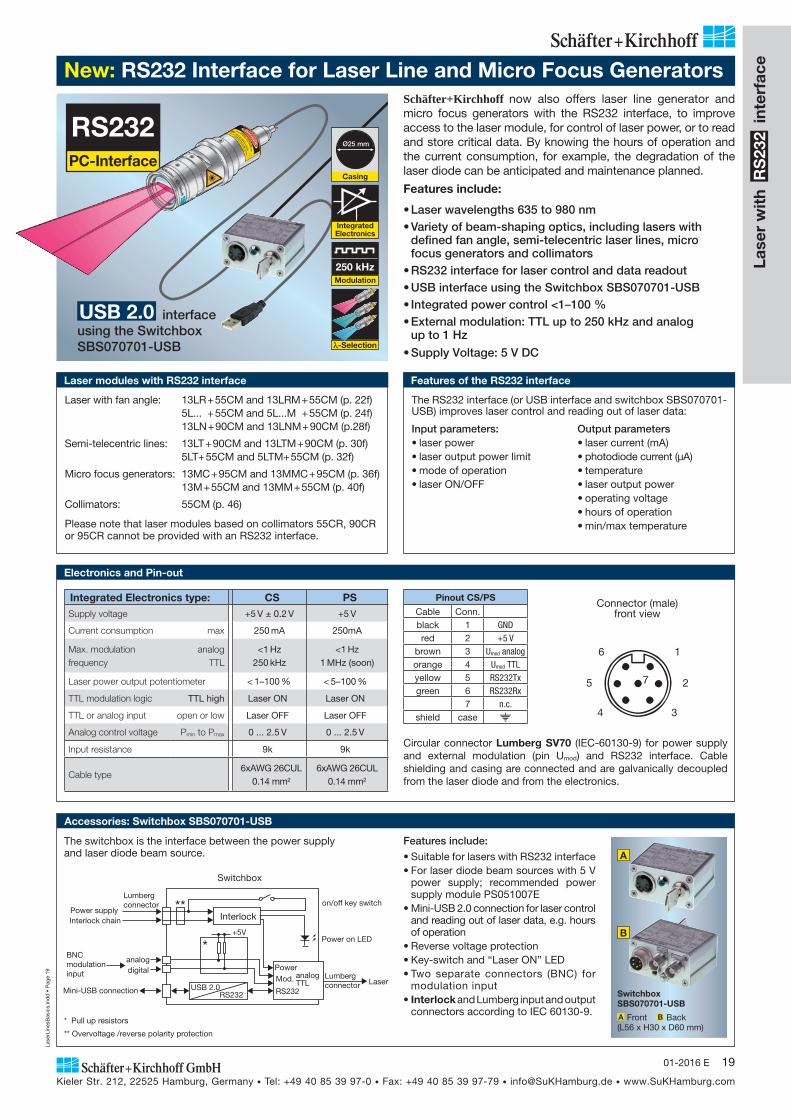
RS232PC-Interface
Integrated Electronics type: CS PSSupply voltage +5 V ± 0.2 V +5 V
Current consumption max 250 mA 250mA
Max. modulation frequency
analog TTL
<1 Hz 250 kHz
<1 Hz 1 MHz (soon)
Laser power output potentiometer < 1–100 % < 5–100 %
TTL modulation logic TTL high Laser ON Laser ON
TTL or analog input open or low Laser OFF Laser OFF
Analog control voltage Pmin to Pmax 0 ... 2.5 V 0 ... 2.5 V
Input resistance 9k 9k
Cable type6xAWG 26CUL
0.14 mm2
6xAWG 26CUL 0.14 mm2
Pinout CS/PS
Cable Conn.black 1 GNDred 2 +5 V
brown 3 Umod analogorange 4 Umod TTLyellow 5 RS232Txgreen 6 RS232Rx
7 n.c.shield case
Circular connector Lumberg SV70 (IEC-60130-9) for power supply and external modulation (pin Umod) and RS232 interface. Cable shielding and casing are connected and are galvanically decoupled from the laser diode and from the electronics.
Connector (male) front view
1
2
34
5
6
7
New: RS232 Interface for Laser Line and Micro Focus GeneratorsSchäfter+Kirchhoff now also offers laser line generator and micro focus generators with the RS232 interface, to improve access to the laser module, for control of laser power, or to read and store critical data. By knowing the hours of opera tion and the current consumption, for example, the degradation of the laser diode can be anticipated and maintenance planned.
Features include:
• Laser wavelengths 635 to 980 nm• Variety of beam-shaping optics, including lasers with
defined fan angle, semi-telecentric laser lines, micro focus generators and collimators
• RS232 interface for laser control and data readout• USB interface using the Switchbox SBS070701-USB• Integrated power control <1–100 %• External modulation: TTL up to 250 kHz and analog
up to 1 Hz
• Supply Voltage: 5 V DC
Electronics and Pin-out
Accessories: Switchbox SBS070701-USB
The switchbox is the interface between the power supply and laser diode beam source.
BNC modulationinput
on/off key switch
Power on LED
Lumberg connector
Lumberg connector
Power supply
Switchbox
LaserMini-USB connection
Interlock
RS232USB 2.0
Poweranalogdigital
Interlock chain
+5V
*
**
TTLRS232
Mod. analog
* Pull up resistors
** Overvoltage /reverse polarity protection
Laser with fan angle: 13LR + 55CM and 13LRM + 55CM (p. 22f) 5L... + 55CM and 5L...M + 55CM (p. 24f) 13LN + 90CM and 13LNM + 90CM (p.28f)
Semi-telecentric lines: 13LT + 90CM and 13LTM + 90CM (p. 30f) 5LT+ 55CM and 5LTM+ 55CM (p. 32f)
Micro focus generators: 13MC + 95CM and 13MMC + 95CM (p. 36f) 13M + 55CM and 13MM + 55CM (p. 40f)
Collimators: 55CM (p. 46)
Please note that laser modules based on collimators 55CR, 90CR or 95CR cannot be provided with an RS232 interface.
Laser modules with RS232 interface
The RS232 interface (or USB interface and switchbox SBS070701-USB) improves laser control and reading out of laser data:
Input parameters:• laser power• laser output power limit• mode of operation• laser ON/OFF
Output parameters• laser current (mA)• photodiode current (μA)• temperature• laser output power• operating voltage• hours of operation• min/max temperature
Features of the RS232 interface
Switchbox SBS070701-USB
A Front B Back (L56 x H30 x D60 mm)
A
B
USB 2.0 interface using the Switchbox SBS070701-USB
Features include:
• Suitable for lasers with RS232 interface• For laser diode beam sources with 5 V
power supply; recommended power supply module PS051007E
• Mini-USB 2.0 connection for laser control and reading out of laser data, e.g. hours of operation
• Reverse voltage protection• Key-switch and “Laser ON” LED• Two separate connectors (BNC) for
modulation input• Interlock and Lumberg input and output
connectors according to IEC 60130-9.
Integrated Electronics
250 kHzModulation
-Selection
Casing
Ø25 mm
Lase
r w
ith
RS
232
inte
rfac
e
Lase
rLin
esB
asic
s.in
dd
• P
age
20
Kieler Str. 212, 22525 Hamburg, Germany • Tel: +49 40 85 39 97-0 • Fax: +49 40 85 39 97-79 • [email protected] • www.SuKHamburg.com
20 01-2016 E
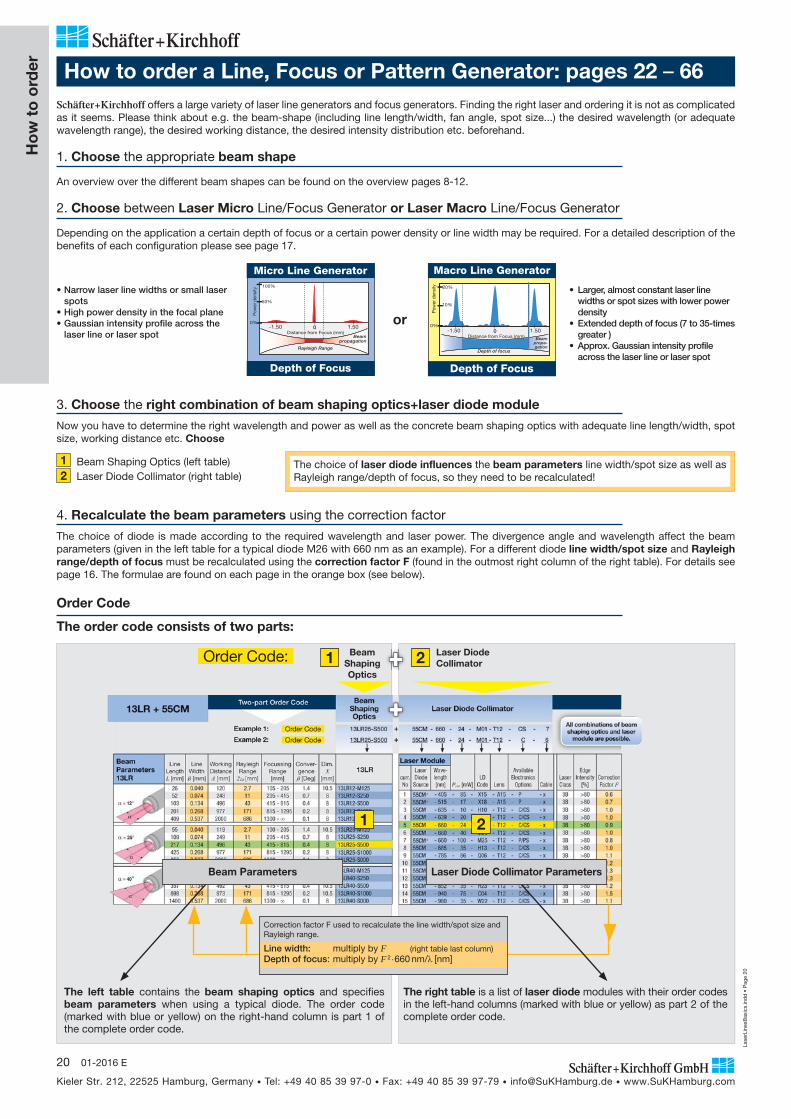
How to order a Line, Focus or Pattern Generator: pages 22 – 66Schäfter+Kirchhoff offers a large variety of laser line generators and focus generators. Finding the right laser and ordering it is not as complicated as it seems. Please think about e.g. the beam-shape (including line length/width, fan angle, spot size...) the desired wavelength (or adequate wavelength range), the desired working distance, the desired intensity distribution etc. beforehand.
1. Choose the appropriate beam shape
An overview over the different beam shapes can be found on the overview pages 8-12.
2. Choose between Laser Micro Line/Focus Generator or Laser Macro Line/Focus Generator
Depending on the application a certain depth of focus or a certain power density or line width may be required. For a detailed description of the benefits of each configuration please see page 17.
X2
0%
50%
100%
Pow
er d
ensi
ty
Rayleigh Range
Beampropagation
0 1.50-1.50Distance from Focus (mm)
Micro Line Generator
Depth of Focus
0%
10%
20%
0 1.50-1.50
Depth of focus
Pow
er d
ensi
ty
Distance from Focus (mm) Beampropa-gation
Depth of Focus
Macro Line Generator
• Narrow laser line widths or small laser spots
• High power density in the focal plane• Gaussian intensity profile across the
laser line or laser spot
• Larger, almost constant laser line widths or spot sizes with lower power density
• Extended depth of focus (7 to 35-times greater )
• Approx. Gaussian intensity profile across the laser line or laser spot
3. Choose the right combination of beam shaping optics+laser diode module
Now you have to determine the right wavelength and power as well as the concrete beam shaping optics with adequate line length/width, spot size, working distance etc. Choose
1 Beam Shaping Optics (left table)2 Laser Diode Collimator (right table)
The left table contains the beam shaping optics and specifies beam parameters when using a typical diode. The order code (marked with blue or yellow) on the right-hand column is part 1 of the complete order code.
or
Correction factor F used to recalculate the line width/spot size and Rayleigh range.
Line width: multiply by F (right table last column)Depth of focus: multiply by F 2 660 nm/ [nm]
1 2
Beam Parameters
The right table is a list of laser diode modules with their order codes in the left-hand columns (marked with blue or yellow) as part 2 of the complete order code.
Ho
w t
o o
rder
4. Recalculate the beam parameters using the correction factor
The choice of diode is made according to the required wavelength and laser power. The divergence angle and wavelength affect the beam parameters (given in the left table for a typical diode M26 with 660 nm as an example). For a different diode line width/spot size and Rayleigh range/depth of focus must be recalculated using the correction factor F (found in the outmost right column of the right table). For details see page 16. The formulae are found on each page in the orange box (see below).
BeamShapingOptics
Laser Diode Collimator 1 2
Order Code
The order code consists of two parts:
Order Code:
The choice of laser diode influences the beam parameters line width/spot size as well as Rayleigh range/depth of focus, so they need to be recalculated!
Laser Diode Collimator Parameters

Lase
rLin
esB
asic
s.in
dd
• P
age
21
Kieler Str. 212, 22525 Hamburg, Germany • Tel: +49 40 85 39 97-0 • Fax: +49 40 85 39 97-79 • [email protected] • www.SuKHamburg.com
2101-2016 E
Ho
w t
o o
rderHow to order a Line, Focus or Pattern Generator: Example
All combinations of beamshaping optics and laser
module are possible.
BeamShapingOptics
Laser Diode Collimator
Details about the electronics are found on page 68.
Two-part Order Code13LR + 55CM
Cable Options: 1.5 m shielded connection cable .............................................................................................................................................................................1 As 1, with connector type Lumberg SV50 (only electronics types C, P) ..............................................................................................................6 1.5 m shielded connection cable, with connector type Lumberg SV70 (only electronics types with interface CS, PS) .....................................7 customer-specified cable length ............................................................................................................................................................... 5
Casing Type:
Casing Type A1 ............................... 55CMCasing Type B1 (only electronics type C) ................... 55CR
* not offered with 55CR (Casing type B1 )
Electronics Options: Please choose one of the stated options. Standard electronics .........................................................................................................................C or P Electronics with RS232 interface ................................................................................................. CS or PS
Example 1: Order Code 13LR25-S500 + 55CM - 660 - 10 - H10 - T12 - CS - 7
Example 2: Order Code 13LR25-S500 + 55CM - 660 - 10 - H10 - T12 - C - 6
RS232PC
INTER-
FACE
optional:
Correction factor F: Properties of the laser diode, such as divergence angle and wavelength, affect the width and Rayleigh range/depth of focus of the laser line:
Line width: multiply by F (right table last column) Rayleigh range: multiply by F 2 660 nm/ [nm]
Example: 13LR25-S500+55CM-660-24-M01-T12-C-6 F = 0.9 (right table last column) Line width B=0.134 mm F = 0.134 mm 0.9 = 0.121 mm Rayleigh range 2zR = 43 mm F2 660 nm / 660 nm = 35 mm
This particular example shows how to choose the correct laser, determine its beam characteristics and determine the correct order code based on some exemplary featuresThe desired laser module is supposed to possess the following exemplary features:
• Laser line with a fan angle• Relatively small line width• Homogeneous intensity distribution• RS232-interface
1. Choose the appropriate beam shape• Looking at the overview on page 8-12 you can see that there are three different types for laser lines with a fan angle: 13LR+55CM (pages
22-23), 5L+25CM (pages 23-24), 5L+55CM (pages 25-26) as well as 13LN+90CM (pages 27-28).• Since you want a homogeneous intensity distribution only the types 13LR+55CM as well as 13LN+90CM come into consideration.• Taking a look at the left tables specifying the beam parameters on each laser page you can see that the 13LN+90CM does not offer such a
long line at the desired working distance (max. line length for about 500 mm working distance is 152 mm). • Thus the correct choice of laser is the type13LR+55CM.
2. Micro line Generator or Macro Line Generator Since you want a small line you need to choose the micro line generator (smaller lines, high power density) of type 13LR+55CM on page 22.
The adequate table with beam parameters and appropriate laser diode collimators is shown below.
3. Right combination of beam shaping optics+laser diode module• The beam shaping optics with parameters closest to the desired features is 13LR25-S500 (features marked green) with a nominal line length
L =217 mm and line width B = 0.134 mm at working distance 496 mm. The first part of the order code is 13LR25-S500 (marked yellow).• Looking at the right table the correct choice for a 660 nm laser with about 20 mW is the laser diode module in row 5 (features marked green).
The adequate order code is marked in yellow. After choosing casing type A1 ("55CM"), the electronics with RS232-interface ("CS") and cable option "7" the second part of the order code is 55CM-660-24- M01-T12-CS-7.
The complete Order Code is: 13LR25-S500+55CM-660-24- M01-T12-CS-7.
4. Recalculate the beam parameters
Since the values for the beam parameters in the left table are presented for a typical diode (M26, 660 nm), the line width and Rayleigh range require recalculation using the correction factor F (details page 16). F is specified in the outmost right column (marked orange). In this case F = 0.9. Using the formulae given in the box below the tables this results in a line width B = 0.12 mm and Rayleigh range 2zR = 35 mm.
If this laser module were to be used at a working distance of 600 mm, using the formulae on page 16 the line width would be calculated to be B = 0.11 mm and the line length would be L = 250 mm.
• Line length L about 220 mm • Working distance about 500 mm• Visible laser with 660 nm with about 20 mW
Choose one
Choose one
Choose one
BeamParameters13LR
Line Length L [mm]
Line Width
B [mm]
Working Distance A [mm]
Rayleigh Range
2zR [mm]
Focussing Range [mm]
Conver- gence ß [Deg]
Dim. X
[mm]13LR
26 0.042 120 2.9 105 - 205 1.4 10.5 13LR12-M125 52 0.077 248 12 205 - 415 0.7 8 13LR12-S250
103 0.139 496 46 415 - 815 0.3 8 13LR12-S500 201 0.278 977 184 815 - 1295 0.2 8 13LR12-S1000 409 0.557 2000 738 1300 - 0.1 8 13LR12-S000
55 0.042 119 2.9 100 - 205 1.4 10.5 13LR25-M125 109 0.077 249 12 205 - 415 0.7 8 13LR25-S250 217 0.139 496 46 415 - 815 0.3 8 13LR25-S500 425 0.278 977 184 815 - 1295 0.2 8 13LR25-S1000 850 0.557 2000 738 1300 - 0.1 8 13LR25-S000
90 0.042 120 2.9 100 - 205 1.4 15 13LR40-M125 180 0.077 245 12 205 - 415 0.7 10.5 13LR40-S250 357 0.139 492 46 415 - 815 0.3 10.5 13LR40-S500 698 0.278 973 184 815 - 1295 0.2 10.5 13LR40-S1000
1400 0.557 2000 738 1300 - 0.1 8 13LR40-S000
= 25°
= 40°
= 12°
Laser Module
Pout [mW]LD
Code Lens
AvailableElectronics
Options CableLaser Class
Edge Intensity
[%]Correction Factor F
curr.No
Laser Diode Source
Wave-length [nm]
1 55CM* - 405 - 14 - Y07 - A15 - P/PS - x 3B >80 0.6 2 55CM* - 405 - 85 - X15 - A15 - P/PS - x 3B >80 0.6 3 55CM* - 450 - 56 - O06 - A15 - P/PS - x 3B >80 0.8 4 55CM* - 515 - 70 - X17 - A15 - P/PS - x 3B >80 0.7 5 55CM - 635 - 10 - H10 - T12 - C/CS - x 3B >80 1.0 6 55CM - 639 - 21 - H18 - T12 - C/CS - x 3B >80 1.0 7 55CM - 660 - 24 - M01 - T12 - C/CS - x 3B >80 0.9 8 55CM - 660 - 40 - M26 - T12 - C/CS - x 3B >80 1.0 9 55CM* - 660 - 100 - M25 - T12 - P/PS - x 3B >80 0.8 10 55CM - 685 - 35 - H13 - T12 - C/CS - x 3B >80 1.0 11 55CM - 785 - 86 - Q06 - T12 - C/CS - x 3B >80 1.1 12 55CM - 830 - 35 - H19 - T12 - C/CS - x 3B >80 1.2 13 55CM - 830 - 107 - N23 - T12 - C/CS - x 3B >80 1.3 14 55CM - 852 - 35 - H23 - T12 - C/CS - x 3B >80 1.2 15 55CM - 940 - 75 - C04 - T12 - C/CS - x 3B >80 1.5
Exemplary Laser Module Table:
Lase
rLin
es13
MC
.ind
d •
Pag
e 36
Kieler Str. 212, 22525 Hamburg, Germany • Tel: +49 40 85 39 97-0 • Fax: +49 40 85 39 97-79 • [email protected] • www.SuKHamburg.com
36 01-2016 E
Integrated Electronics
100 kHzModulation
Ø25 mm
Casing -Selection
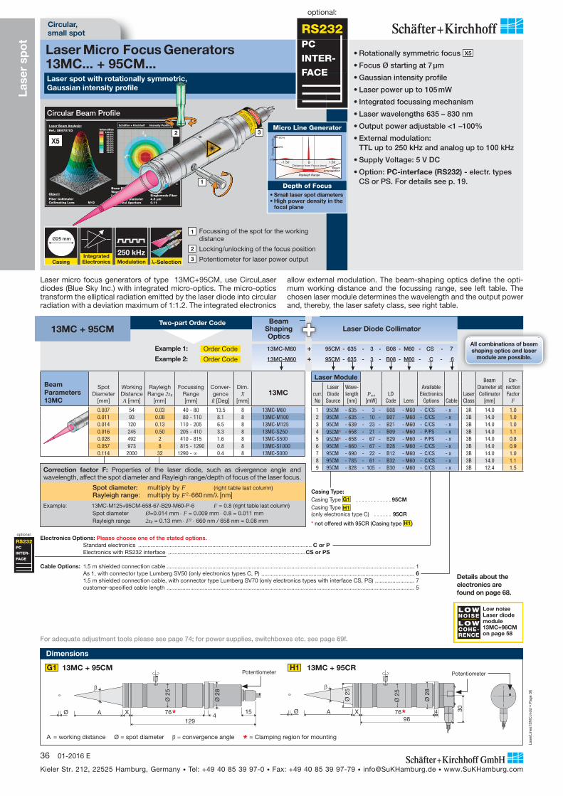
Laser spot with rotationally symmetric, Gaussian intensity profile
Laser Micro Focus Generators 13MC... + 95CM...
Lase
r sp
ot
Circular, small spot
0%
50%
100%
Pow
er d
ensi
ty
Rayleigh Range
Beampropagation
0 1.50-1.50Distance from Focus (mm)
Micro Line Generator
Depth of Focus• Small laser spot diameters • High power density in the
focal plane
• Rotationally symmetric focus X5
• Focus Ø starting at 7 μm
• Gaussian intensity profile
• Laser power up to 105 mW
• Integrated focussing mechanism
• Laser wavelengths 635 – 830 nm
• Output power adjustable <1 –100%
• External modulation: TTL up to 250 kHz and analog up to 100 kHz
• Supply Voltage: 5 V DC
• Option: PC-interface (RS232) - electr. types CS or PS. For details see p. 19.
1 Focussing of the spot for the working distance
2 Locking/unlocking of the focus position
3 Potentiometer for laser power output250 kHz
All combinations of beamshaping optics and laser
module are possible.
BeamShapingOptics
Laser Diode Collimator
Details about the electronics are found on page 68.
Two-part Order Code13MC + 95CM
Circular Beam ProfileSchäfter + Kirchhoff Intensity ProfileLaser Beam Analysis:
Ref.: SK970703 Intensities100.0%
90.0%80.0%70.0%60.0%50.0%40.0%30.0%20.0%10.0%
Object:
Fiber CollimatorCollimating Lens M12
Beam Diameter (1/e2) 2.18 mmWavelength 635 nmLasersource Singlemode FiberMode Field Diameter 4.5 μmNumerical Aperture 0.11
RS232PC
INTER-
FACE
Cable Options: 1.5 m shielded connection cable ............................................................................................................................................................. 1 As 1, with connector type Lumberg SV50 (only electronics types C, P) ................................................................................................. 6 1.5 m shielded connection cable, with connector type Lumberg SV70 (only electronics types with interface CS, PS) ......................... 7 customer-specified cable length ............................................................................................................................................................. 5
Casing Type:Casing Type G1 . . . . . . . . . . . . 95CMCasing Type H1 (only electronics type C) . . . . . . 95CR
* not offered with 95CR (Casing type H1 )
Electronics Options: Please choose one of the stated options. Standard electronics .............................................................................................................. C or P Electronics with RS232 interface .......................................................................................CS or PS
Example 1: Order Code 13MC-M60 + 95CM - 635 - 3 - B08 - M60 - CS - 7
Example 2: Order Code 13MC-M60 + 95CM - 635 - 3 - B08 - M60 - C - 6
RS232PC
INTER-
FACE
optional:
Correction factor F: Properties of the laser diode, such as divergence angle and wavelength, affect the spot diameter and Rayleigh range/depth of focus of the laser focus.
Spot diameter: multiply by F (right table last column) Rayleigh range: multiply by F 2 660 nm/ [nm]
Example: 13MC-M125+95CM-658-67-B29-M60-P-6 F = 0.8 (right table last column) Spot diameter Ø=0.014 mm F = 0.009 mm 0.8 = 0.011 mm Rayleigh range 2zR = 0.13 mm F2 660 nm / 658 nm = 0.08 mm
Beam Parameters13MC
Spot Diameter
[mm]
Working Distance A [mm]
Rayleigh Range 2zR
[mm]
Focussing Range [mm]
Conver- gence ß [Deg]
Dim. X
[mm]13MC
0.007 54 0.03 40 - 80 13.5 8 13MC-M60 0.011 93 0.08 80 - 110 8.1 8 13MC-M100 0.014 120 0.13 110 - 205 6.5 8 13MC-M125 0.016 245 0.50 205 - 410 3.3 8 13MC-S250 0.028 492 2 410 - 815 1.6 8 13MC-S500 0.057 973 8 815 - 1290 0.8 8 13MC-S1000 0.114 2000 32 1290 - 0.4 8 13MC-S000
LOWNOISELOWCOHE-RENCE
Low noise Laser diode module 13MC+96CM on page 58
Laser Module
Pout [mW]
LD Code Lens
AvailableElectronics
Options CableLaser Class
Beam Diameter at Collimator
[mm]
Cor-rection Factor
Fcurr.No
Laser Diode Source
Wave-length [nm]
1 95CM - 635 - 3 - B08 - M60 - C/CS - x 3R 14.0 1.0 2 95CM - 635 - 10 - B07 - M60 - C/CS - x 3B 14.0 1.0 3 95CM - 639 - 23 - B21 - M60 - C/CS - x 3B 14.0 1.0 4 95CM* - 658 - 21 - B09 - M60 - P/PS - x 3B 14.0 1.1 5 95CM* - 658 - 67 - B29 - M60 - P/PS - x 3B 14.0 0.8 6 95CM - 660 - 67 - B28 - M60 - C/CS - x 3B 14.0 0.9 7 95CM - 690 - 22 - B12 - M60 - C/CS - x 3B 14.0 1.0 8 95CM - 785 - 61 - B32 - M60 - C/CS - x 3B 14.0 1.1 9 95CM - 828 - 105 - B30 - M60 - C/CS - x 3B 12.4 1.5
3
1
2
X5
For adequate adjustment tools please see page 74; for power supplies, switchboxes etc. see page 69f.
Dimensions
15476
129
XAØ
Ø 2
8
Ø 2
5
Ø 30
47698
X
Ø 2
5
Ø 2
5
Ø 2
8
A
Potentiometer PotentiometerG1 13MC + 95CM H1 13MC + 95CR
A = working distance Ø = spot diameter convergence angle * = Clamping region for mounting
optional:
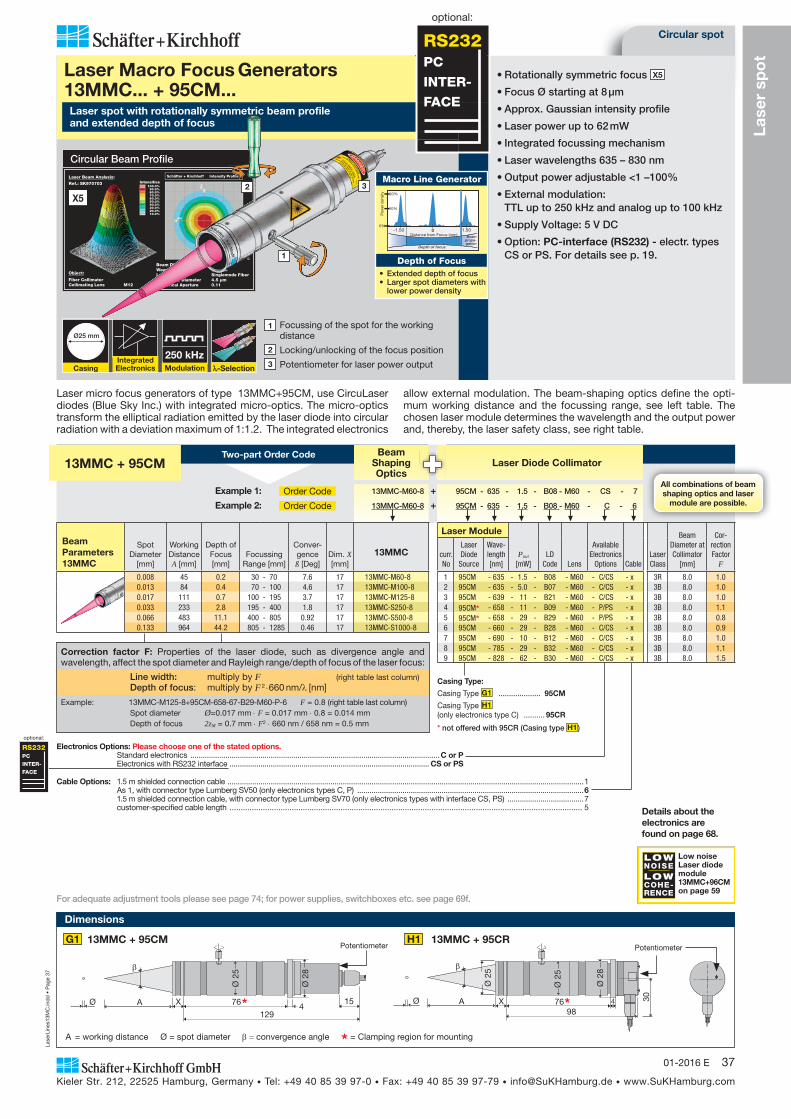
Laser micro focus generators of type 13MC+95CM, use CircuLaser diodes (Blue Sky Inc.) with integrated micro-optics. The micro-optics transform the elliptical radiation emitted by the laser diode into circular radiation with a deviation maximum of 1:1.2. The integrated electronics
allow external modulation. The beam-shaping optics define the opti-mum working distance and the focussing range, see left table. The chosen laser module determines the wavelength and the output power and, thereby, the laser safety class, see right table.
Lase
rLin
es13
MC
.ind
d •
Pag
e 37
Kieler Str. 212, 22525 Hamburg, Germany • Tel: +49 40 85 39 97-0 • Fax: +49 40 85 39 97-79 • [email protected] • www.SuKHamburg.com
3701-2016 E
For adequate adjustment tools please see page 74; for power supplies, switchboxes etc. see page 69f.
Circular spot
Lase
r sp
ot
Cable Options: 1.5 m shielded connection cable .............................................................................................................................................................................1 As 1, with connector type Lumberg SV50 (only electronics types C, P) ..............................................................................................................6 1.5 m shielded connection cable, with connector type Lumberg SV70 (only electronics types with interface CS, PS) .....................................7 customer-specified cable length ............................................................................................................................................................... 5
Casing Type:
Casing Type G1 .................... 95CM
Casing Type H1 (only electronics type C) .......... 95CR
* not offered with 95CR (Casing type H1 )
Electronics Options: Please choose one of the stated options. Standard electronics .........................................................................................................................C or P Electronics with RS232 interface ................................................................................................. CS or PS
All combinations of beamshaping optics and laser
module are possible.
BeamShapingOptics
Laser Diode Collimator 13MMC + 95CMTwo-part Order Code
Example 1: Order Code 13MMC-M60-8 + 95CM - 635 - 1.5 - B08 - M60 - CS - 7
Example 2: Order Code 13MMC-M60-8 + 95CM - 635 - 1.5 - B08 - M60 - C - 6
Correction factor F: Properties of the laser diode, such as divergence angle and wavelength, affect the spot diameter and Rayleigh range/depth of focus of the laser focus:
Line width: multiply by F (right table last column) Depth of focus: multiply by F 2 660 nm/ [nm]
Example: 13MMC-M125-8+95CM-658-67-B29-M60-P-6 F = 0.8 (right table last column) Spot diameter Ø=0.017 mm F = 0.017 mm 0.8 = 0.014 mm Depth of focus 2zM = 0.7 mm F2 660 nm / 658 nm = 0.5 mm
RS232PC
INTER-
FACE
optional:
LOWNOISELOWCOHE-RENCE
Low noise Laser diode module 13MMC+96CM on page 59
BeamParameters13MMC
Spot Diameter
[mm]
Working Distance A [mm]
Depth of Focus
[mm]Focussing
Range [mm]
Conver- gence ß [Deg]
Dim. X [mm]
13MMC
0.008 45 0.2 30 - 70 7.6 17 13MMC-M60-8 0.013 84 0.4 70 - 100 4.6 17 13MMC-M100-8 0.017 111 0.7 100 - 195 3.7 17 13MMC-M125-8 0.033 233 2.8 195 - 400 1.8 17 13MMC-S250-8 0.066 483 11.1 400 - 805 0.92 17 13MMC-S500-8 0.133 964 44.2 805 - 1285 0.46 17 13MMC-S1000-8
Laser Module
Pout [mW]
LD Code Lens
AvailableElectronics
Options CableLaser Class
Beam Diameter at Collimator
[mm]
Cor-rection Factor
Fcurr.No
Laser Diode Source
Wave-length [nm]
1 95CM - 635 - 1.5 - B08 - M60 - C/CS - x 3R 8.0 1.0 2 95CM - 635 - 5.0 - B07 - M60 - C/CS - x 3B 8.0 1.0 3 95CM - 639 - 11 - B21 - M60 - C/CS - x 3B 8.0 1.0 4 95CM* - 658 - 11 - B09 - M60 - P/PS - x 3B 8.0 1.1 5 95CM* - 658 - 29 - B29 - M60 - P/PS - x 3B 8.0 0.8 6 95CM - 660 - 29 - B28 - M60 - C/CS - x 3B 8.0 0.9 7 95CM - 690 - 10 - B12 - M60 - C/CS - x 3B 8.0 1.0 8 95CM - 785 - 29 - B32 - M60 - C/CS - x 3B 8.0 1.1 9 95CM - 828 - 62 - B30 - M60 - C/CS - x 3B 8.0 1.5
Integrated Electronics
100 kHzModulation
Ø25 mm
Casing -Selection
Laser micro focus generators of type 13MMC+95CM, use CircuLaser diodes (Blue Sky Inc.) with integrated micro-optics. The micro-optics transform the elliptical radiation emitted by the laser diode into circular radiation with a deviation maximum of 1:1.2. The integrated electronics
allow external modulation. The beam-shaping optics define the opti-mum working distance and the focussing range, see left table. The chosen laser module determines the wavelength and the output power and, thereby, the laser safety class, see right table.
Laser spot with rotationally symmetric beam profile and extended depth of focus
Laser Macro Focus Generators 13MMC... + 95CM...
• Rotationally symmetric focus X5
• Focus Ø starting at 8 μm
• Approx. Gaussian intensity profile
• Laser power up to 62 mW
• Integrated focussing mechanism
• Laser wavelengths 635 – 830 nm
• Output power adjustable <1 –100%
• External modulation: TTL up to 250 kHz and analog up to 100 kHz
• Supply Voltage: 5 V DC
• Option: PC-interface (RS232) - electr. types CS or PS. For details see p. 19.
1 Focussing of the spot for the working distance
2 Locking/unlocking of the focus position
3 Potentiometer for laser power output250 kHz
Circular Beam ProfileSchäfter + Kirchhoff Intensity ProfileLaser Beam Analysis:
Ref.: SK970703 Intensities100.0%
90.0%80.0%70.0%60.0%50.0%40.0%30.0%20.0%10.0%
Object:
Fiber CollimatorCollimating Lens M12
Beam Diameter (1/e2) 2.18 mmWavelength 635 nmLasersource Singlemode FiberMode Field Diameter 4.5 μmNumerical Aperture 0.11
RS232PC
INTER-
FACE
3
1
2
X5
0%
10%
20%
0 1.50-1.50
Depth of focus
Pow
er d
ensi
ty
Distance from Focus (mm) Beampropa-gation
Macro Line Generator
Depth of Focus• Extended depth of focus• Larger spot diameters with
lower power density
Details about the electronics are found on page 68.
Dimensions
15476
129
XAØ
Ø 2
8
Ø 2
5
Ø 30
47698
X
Ø 2
5
Ø 2
5
Ø 2
8
A
Potentiometer PotentiometerG1 13MMC + 95CM H1 13MMC + 95CR
A = working distance Ø = spot diameter convergence angle * = Clamping region for mounting
optional:

Lase
rLin
es13
MC
.ind
d •
Pag
e 38
Kieler Str. 212, 22525 Hamburg, Germany • Tel: +49 40 85 39 97-0 • Fax: +49 40 85 39 97-79 • [email protected] • www.SuKHamburg.com
38 01-2016 E
All combinations of beamshaping optics and laser
module are possible.
Micro FocusOptics
Laser Diode Collimator 5MC + 29CMTwo-part Order Code
Example 1: Order Code 5MC-A11 + 29CM - 785 - 75 - B32 - M12 - S - 6
Example 2: Order Code 5MC-A11 + 29CM - 635 - 4 - B08 - M12 - S - 6
BeamParameters5MC
Spot Diameter
[mm]
Working Distance A [mm]
Rayleigh Range
2zR [mm]
Focussing Range [mm]
Conver- gence ß [Deg]
Dim. X
[mm]5MC
0.002 3 0.01 2 - 6 25.8 4.5 5MC-A6.2 0.004 7.4 0.02 6 - 15 14.7 4.5 5MC-A11 0.006 16.5 0.06 15 - 35 9.0 4.5 5MC-A18 0.018 46 0.50 35 - 70 3.3 1.2 5MC-S50 0.031 82 1.6 70 - 125 1.9 1.2 5MC-S88 0.051 147 4.5 125 - 260 1.1 1.2 5MC-S150 0.094 317 22 260 - 430 0.5 1.2 5MC-S330
Cable Options:1.5 m shielded connection cable . . . . . . . . . . . 1As 1, with connector type Lumberg SV40 (electronics type B only) . . . . . . 4As 1, with connector type Lumberg SV50 (electronics type S only) . . . . . . 6customer-specified cable length . .5
Laser Module
Pout [mW]
LD Code Lens
Elec-tronics Cable
Laser Class
Beam Diameter at Collimator
[mm]Correction Factor F
curr.No
Laser Diode Source
Wave-length [nm]
1 29CM - 635 - 4 - B08 - M12 - S - x 3R 2.8 1.0 2 29CM - 635 - 11 - B07 - M12 - S - x 3B 2.8 1.0 3 29CM - 639 - 26 - B21 - M12 - S - x 3B 2.8 1.0 4 29CM - 658 - 24 - B09 - M12 - S - x 3B 2.8 1.1 5 29CM - 658 - 89 - B29 - M12 - S - x 3B 3.5 0.8 6 29CM - 660 - 89 - B28 - M12 - S - x 3B 3.5 0.9 7 29CM - 690 - 26 - B12 - M12 - S - x 3B 3.0 1.0 8 29CM - 785 - 75 - B32 - M12 - S - x 3B 3.2 1.1 9 29CM - 828 - 114 - B30 - M12 - S - x 3B 2.5 1.5
Integrated Electronics
100 kHzModulation
Ø12 mm
Casing -Selection
Laser micro focus generators of type 5MC+29CM, use CircuLaser di-odes (Blue Sky Inc.) with integrated micro-optics. The micro-optics transform the elliptical radiation emitted by the laser diode into circular radiation with a deviation maximum of 1:1.2. The integrated electronics
allow external modulation. The beam-shaping optics define the opti-mum working distance and the focussing range, see left table. The chosen laser module determines the wavelength and the output power and, thereby, the laser safety class, see right table.
Compact laser spot generator with rotationally symmetric beam profile and Gaussian intensity profile
Laser Focus Generator5MC-... + 29CM...
Dimensions
Lase
r sp
ot
Compact, circular, small spot
0%
50%
100%
Pow
er d
ensi
ty
Rayleigh Range
Beampropagation
0 1.50-1.50Distance from Focus (mm)
Micro Line Generator
Depth of Focus• Small laser spot diameters • High power density in the
focal plane
• Rotationally symmetric focus
• Focus Ø starting at 2 μm
• Gaussian intensity profile X5
• Integrated focussing mechanism
• Spectral range 635 – 830 nm
• Laser power up to 114 mW
• Output power adjustable <30 –100%
• External modulation: TTL up to 1 MHz and analog up to 100 kHz
• Supply voltage 5 V DC
• Rev. polarity / overvoltage protection
1 Focussing of the spot for the working distance
2 Locking/unlocking of the focus position
3 Potentiometer for laser power output1 MHz
A = working distance Ø = spot diameter convergence angle * = Clamping region for mounting
Schäfter + Kirchhoff Intensity ProfileLaser Beam Analysis:
Ref.: SK970703 Intensities100.0%
90.0%80.0%70.0%60.0%50.0%40.0%30.0%20.0%10.0%
Object:
Fiber CollimatorCollimating Lens M12
Beam Diameter (1/e2) 2.18 mmWavelength 635 nmLasersource Singlemode FiberMode Field Diameter 4.5 μmNumerical Aperture 0.11
Circular Beam Profile
Details about the electronics are found on page 67.For adequate adjustment tools please see page 74; for power supplies, switchboxes etc. see page 69f.
3
2
1
X5
Correction factor F: Properties of the laser diode, such as divergence angle and wavelength, affect the spot diameter and Rayleigh range/depth of focus of the laser focus.
Line width: multiply by F (right table last column) Rayleigh range: multiply by F 2 660 nm/ [nm]
Example: 5MC-A11+29CM-785-75-B32-M12-S-6 F = 1.1 (right table last column) Spot diameter Ø=0.004 mm F = 0.004 mm 1.1 = 0.004 mm Rayleigh range 2zR = 0.02 mm F2 660 nm / 785 nm = 0.02 mm
D1
X 3364
31A
Ø12
Ø
Potentiometer5MC + 29CM
Lase
rLin
es13
M.in
dd
• P
age
40
Kieler Str. 212, 22525 Hamburg, Germany • Tel: +49 40 85 39 97-0 • Fax: +49 40 85 39 97-79 • [email protected] • www.SuKHamburg.com
40 01-2016 E
Elliptical beam profile
X6
Cable Options:1.5 m shielded connection cable .......................................................................................................................................................................................................1As 1, with connector type Lumberg SV50 (only electronics types C, P) ........................................................................................................................................61.5 m shielded connection cable, with connector type Lumberg SV70 (only electronics types with interface CS, PS) ...............................................................7customer-specified cable length ....................................................................................................................................................................................... 5
Casing Type:Casing Type A4 ........................................................................... 55CMCasing Type B4 (only electronics type C) .................................... 55CR
* not offered with 55CR (Casing type B4 )
Electronics Options: Please choose one of the stated options.Standard electronics ................................................................................................................................................... C or PElectronics with RS232 interface ............................................................................................................................... CS or PS
13M
Integrated Electronics
250 kHzModulation
Ø25 mm
Casing -Selection
Laser spot with elliptical Gaussian beam profile
Laser Micro Focus Generator13M-... + 55CM...
1 Focussing of the laser line for the working distance
2 Locking/unlocking of the focus position
3 Potentiometer for laser power output
Sem
i-te
lece
ntri
c la
ser
line
Ellipticalspot
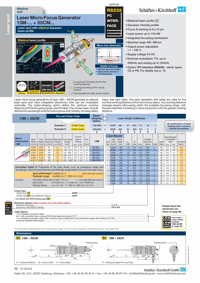
• Elliptical beam profile X6
• Gaussian intensity profile
• Focus Ø starting at 9 x 21 μm
• Laser power up to 114 mW
• Integrated focussing mechanism
• Spectral range 405 – 980 nm
• Output power adjustable < 1 – 100 %
• Supply voltage 5 V DC
• External modulation: TTL up to
250 kHz and analog up to 100 kHz
• Option: PC-interface (RS232) - electr. types CS or PS. For details see p. 19.
0%
50%
100%
Pow
er d
ensi
ty
Rayleigh Range
Beampropagation
0 1.50-1.50Distance from Focus (mm)
Micro Line Generator
Depth of Focus• Narrow laser line widths • High power density in
the focal plane
RS232PC
INTER-
FACE
optional:
Lase
r sp
ot
All combinations of beamshaping optics and laser
module are possible.
BeamShapingOptics
Laser Diode Collimator Two-part Order Code
13M + 55CM
Example 1: Order Code 13M-M60 + 55CM - 660 - 25 - M01 - T12 - CS - 7
Example 2: Order Code 13M-M60 + 55CM - 660 - 25 - M01 - T12 - C - 6
BeamParameters13M
Spot Width
W [mm]
Spot Height H [mm]
Working Distance A [mm]
Rayleigh Range
2zR [mm]
Focussing Range [mm]
Conver-gence ß [Deg]
Dim. X
[mm]13M
perp. par.0.009 0.021 54 0.1 40 - 80 6.9 2.9 8 13M-M60 0.014 0.033 93 0.3 80 - 110 4.1 1.7 8 13M-M100 0.018 0.042 120 0.5 110 - 205 3.3 1.4 8 13M-M125 0.032 0.077 245 2.0 205 - 410 1.6 0.7 8 13M-S250 0.058 0.139 492 8.1 410 - 815 0.8 0.3 8 13M-S500 0.117 0.278 973 33 815 - 1295 0.4 0.2 8 13M-S1000
Laser Module
Pout [mW]
LD Code Lens
AvailableElectronics
Options CableLaser Class
Beam Diameter at Collimator
[mm] Correction Factor F
curr.No
Laser Diode Source
Wave-length [nm] perp. par.
1 55CM* - 405 - 15 - Y07 - A15 - P/PS - x 3B 8.3 3.8 0.6 2 55CM* - 405 - 91 - X15 - A15 - P/PS - x 3B 8.6 4.0 0.6 3 55CM* - 450 - 60 - O06 - A15 - P/PS - x 3B 9.2 3.1 0.8 4 55CM* - 515 - 75 - X17 - A15 - P/PS - x 3B 9.4 3.8 0.7 5 55CM - 635 - 11 - H10 - T12 - C/CS - x 3B 9.7 2.8 1.0 6 55CM - 639 - 22 - H18 - T12 - C/CS - x 3B 10.7 2.8 1.0 7 55CM - 660 - 25 - M01 - T12 - C/CS - x 3B 7.7 3.2 0.9 8 55CM - 660 - 42 - M26 - T12 - C/CS - x 3B 7.2 3.0 1.0 9 55CM* - 660 - 107 - M25 - T12 - P/PS - x 3B 5.8 3.6 0.8
10 55CM - 685 - 38 - H13 - T12 - C/CS - x 3B 7.4 3.0 1.0 11 55CM - 785 - 91 - Q06 - T12 - C/CS - x 3B 5.6 3.2 1.1 12 55CM - 830 - 38 - H19 - T12 - C/CS - x 3B 7.7 3.2 1.2 13 55CM - 830 - 114 - N23 - T12 - C/CS - x 3B 5.6 2.8 1.3 14 55CM - 852 - 38 - H23 - T12 - C/CS - x 3B 7.7 3.2 1.2 15 55CM - 940 - 80 - C04 - T12 - C/CS - x 3B 9.7 2.8 1.5
Laser micro focus generators of type 13M + 95CM generate an ellipical laser spot and have integrated electronics that can be modulated externally. The beam-shaping optics define the optimum work ing distance and the focussing range, see left table. The chosen laser module defines the wavelength and the output power and, thereby, the laser safety
class, see right table. The spot diameters (left table) are valid for the nominal working distance of the micro focus optics. Any working distance changes require refocussing within the available focussing range, with the spot diameter increasing in direct proportion with the greater working distance.
RS232PC
INTER-
FACE
optional:
Correction factor F: Properties of the laser diode, such as divergence angle and wavelength, affect the spot diameter and Rayleigh range/depth of focus of the laser focus.
Spot width/height: multiply by F (right table last column) Rayleigh range: multiply by F 2 660 nm/ [nm]
Example: 13M-M60+55CM-660-25-M01-T12-C-6 F = 0.9 (right table last column) Spot width W=0.009 mm F = 0.009 mm 0.9 = 0.008 mm Rayleigh Range 2zR = 0.1 mm F2 660 nm / 660 nm = 0.1 mm
3052
4 30
XW
H
Ø 2
5
Ø 2
8
AW
H
X83
30 4 4915
9Ø 25
A
Ø 2
8
A4 B413M + 55CM 13M + 55CR
Potentiometer Potentiometer
Dimensions
* = Clamping region for mountingA = working distance W = focus width H = focus height
For adequate adjustment tools please see page 74; for power supplies, switchboxes etc. see page 69f.
Details about the electronics are found on page 68.
LOWNOISELOWCOHE-RENCE
Low noise Laser diode module 13M+56CM on page 60.
2
3
1

Lase
rLin
es13
M.in
dd
• P
age
41
Kieler Str. 212, 22525 Hamburg, Germany • Tel: +49 40 85 39 97-0 • Fax: +49 40 85 39 97-79 • [email protected] • www.SuKHamburg.com
4101-2016 E
Correction factor F: Properties of the laser diode, such as divergence angle and wavelength, affect the spot diameter and Rayleigh range/depth of focus of the laser focus.
Spot diameter: multiply by F (right table last column) Depth of focus: multiply by F 2 660 nm/ [nm]
Example: 13MM-M60-4+55CM-660-16-M01-T12-C-6 F = 0.9 (right table last column) Spot diameter Ø=0.020 mm F = 0.020 mm 0.9 = 0.018 mm Depth of focus 2zM = 0.7 mm F2 660 nm / 660 nm = 0.6 mm
3052
4 30
XW
H
Ø 2
5
Ø 2
8
AW
H
X83
30 4 4915
9Ø 25
A
Ø 2
8
A4 B413MM + 55CM 13MM + 55CR
Potentiometer Potentiometer
Dimensions
* = Clamping region for mountingA = working distance W = focus width H = focus height
Circularspot
Lase
r sp
ot
Schäfter + Kirchhoff Intensity ProfileLaser Beam Analysis:
Ref.: SK970703 Intensities100.0%90.0%80.0%70.0%60.0%50.0%40.0%30.0%20.0%10.0%
Object:
Fiber CollimatorCollimating Lens M12
Beam Diameter (1/e2) 2.18 mmWavelength 635 nmLasersource Singlemode FiberMode Field Diameter 4.5 μmNumerical Aperture 0.11
Circular beam profile
Cable Options:1.5 m shielded connection cable .......................................................................................................................................................................................................1As 1, with connector type Lumberg SV50 (only electronics types C, P) ........................................................................................................................................61.5 m shielded connection cable, with connector type Lumberg SV70 (only electronics types with interface CS, PS) ...............................................................7customer-specified cable length ....................................................................................................................................................................................... 5
Casing Type:Casing Type A4 ........................................................................... 55CMCasing Type B4 (only electronics type C) .................................... 55CR
* not offered with 55CR (Casing type B4 )
Electronics Options: Please choose one of the stated options.Standard electronics ................................................................................................................................................... C or PElectronics with RS232 interface ............................................................................................................................... CS or PS
13MM
Integrated Electronics
250 kHzModulation
Ø25 mm
Casing -Selection
Laser spot with circular beam profile and extended depth of focus
Laser Macro Focus Generator13MM-... + 55CM...
1 Focussing of the laser line for the working distance
2 Locking/unlocking of the focus position
3 Potentiometer for laser power output
• Circular beam profile X5
• Approx. Gaussian intensity profile
• Focus Ø starting at 20 μm
• Laser power up to 89 mW
• Integrated focussing mechanism
• Spectral range 405 – 980 nm
• Output power adjustable < 1 – 100 %
• Supply voltage 5 V DC
• External modulation: TTL up to 250 kHz and analog up to 100 kHz
• Option: PC-interface (RS232) - electr. types CS or PS. For details see p. 19.
RS232PC
INTER-
FACE
optional:
Laser micro focus generators of type 13MM + 95CM generate an ellipical laser spot and have integrated electronics that can be modulated externally. The beam-shaping optics define the optimum work ing distance and the focussing range, see left table. The chosen laser module defines the wavelength and the output power and, thereby, the laser safety
class, see right table. The spot diameters (left table) are valid for the nominal working distance of the micro focus optics. Any working distance changes require refocussing within the available focussing range, with the spot diameter increasing in direct proportion with the greater working distance.
X5
RS232PC
INTER-
FACE
optional:
All combinations of beamshaping optics and laser
module are possible.
BeamShapingOptics
Laser Diode Collimator 13MM + 55CMTwo-part Order Code
Example 1: Order Code 13MM-M60-4 + 55CM - 660 - 16 - M01 - T12 - CS - 7
Example 2: Order Code 13MM-M60-4 + 55CM - 660 - 16 - M01 - T12 - C - 6
BeamParameters13MM
Spot Diameter
[mm]
Working Distance A [mm]
Depth of Focus
[mm]
Focussing Range [mm]
Conver- gence ß [Deg]
Dim. X
[mm]13MM
0.020 45 0.7 40 - 80 2.9 17 13MM-M60-4 0.033 84 1.8 80 - 110 1.7 17 13MM-M100-4 0.041 111 2.9 110 - 205 1.4 17 13MM-M125-4 0.082 233 11 205 - 410 0.7 17 13MM-S250-4 0.165 483 46 410 - 815 0.3 17 13MM-S500-4 0.330 964 184 815 - 1295 0.2 17 13MM-S1000-4
Laser Modules
Pout [mW]
LD Code Lens
AvailableElectronics
Options CableLaser Class
Beam Diameter at Collimator
[mm]Correction Factor F
curr.No.
Laser Diode Source
Wave-length [nm]
1 55CM* - 405 - 8 - Y07 -A15 - P/PS - x 3B 3.8 0.6 2 55CM* - 405 - 49 - X15 -A15 - P/PS - x 3B 4.0 0.6 3 55CM* - 450 - 33 - O06 -A15 - P/PS - x 3B 3.1 0.8 4 55CM* - 515 - 39 - X17 -A15 - P/PS - x 3B 3.8 0.7 5 55CM - 635 - 6 - H10 - T12 - C/CS - x 3B 2.8 1.0 6 55CM - 639 - 11 - H18 - T12 - C/CS - x 3B 2.8 1.0 7 55CM - 660 - 16 - M01 - T12 - C/CS - x 3B 3.2 0.9 8 55CM - 660 - 28 - M26 - T12 - C/CS - x 3B 3.0 1.0 9 55CM* - 660 - 78 - M25 - T12 - P/PS - x 3B 3.6 0.8 10 55CM - 685 - 24 - H13 - T12 - C/CS - x 3B 3.0 1.0 11 55CM - 785 - 70 - Q06 - T12 - C/CS - x 3B 3.2 1.1 12 55CM - 830 - 23 - H19 - T12 - C/CS - x 3B 3.2 1.2 13 55CM - 830 - 89 - N23 - T12 - C/CS - x 3B 2.8 1.3 14 55CM - 852 - 23 - H23 - T12 - C/CS - x 3B 3.2 1.2 15 55CM - 940 - 43 - C04 - T12 - C/CS - x 3B 2.8 1.5
For adequate adjustment tools please see page 74; for power supplies, switchboxes etc. see page 69f.
Details about the electronics are found on page 68.
LOWNOISELOWCOHE-RENCE
Low noise Laser diode module 13MM+56CM on page 61.
3
1
2
0%
10%
20%
0 1.50-1.50
Depth of focus
Pow
er d
ensi
ty
Distance from Focus (mm) Beampropa-gation
Macro Line Generator
Depth of Focus• Extended depth of focus• Larger spot diameters
with lower power density

Lase
rLin
es13
M.in
dd
• P
age
42
Kieler Str. 212, 22525 Hamburg, Germany • Tel: +49 40 85 39 97-0 • Fax: +49 40 85 39 97-79 • [email protected] • www.SuKHamburg.com
42 01-2016 E
Correction factor F: Properties of the laser diode, such as divergence angle and wavelength, affect the spot diameter and Rayleigh range/depth of focus of the laser focus.
Spot width/height: multiply by F (right table last column) Rayleigh range: multiply by F 2 660 nm/ [nm]
Example: 5M-S150+25CM-830-35-H19-A8-S-6 F = 1.2 (right table last column) Spot width W=0.032 mm F = 0.032 mm 1.2 = 0.038 mm Rayleigh Range 2zR = 1.6 mm F2 660 nm / 830 nm = 1.8 mm
Details about the electronics are
found on page 67.
Integrated Electronics
1 MHzModulation
Ø12 mm
Casing -Selection
Compact laser spot with elliptical Gaussian beam profile
Laser Micro Focus Generators 5M... + 25CM...
1 Focussing of the spot for the working distance
2 Locking/unlocking of the focus position
3 Potentiometer for laser power output
Sem
i-te
lece
ntri
c la
ser
line
Compact, elliptical spot
• Elliptical beam profile X6
• Gaussian intensity profile
• Focus Ø starting at 1 x 3 μm
• Laser power up to 90 mW
• Integrated focussing mechanism
• Spectral range 635 – 852nm
• Output power adjustable <30 –100 %
• Supply Voltage: 5V DC
• External modulation: TTL up to 1 Mhz and analog up to 100 kHz
• Rev. polarity/overvoltage protection
0%
50%
100%
Pow
er d
ensi
ty
Rayleigh Range
Beampropagation
0 1.50-1.50Distance from Focus (mm)
Micro Line Generator
Depth of Focus• Small laser spot diameters • High power density in the
focal plane
Lase
r sp
ot
All combinations of beamshaping optics and laser
module are possible.
BeamShapingOptics
Laser Diode Collimator Two-part Order Code
5M + 25CM
Example 1: Order Code 5M-A11 + 25CM - 830 - 35 - H19 - A8 - S - 6
Example 2: Order Code 5M-A11 + 25CM - 660 - 40 - M26 - A8 - S - 6
Laser micro focus generators of type 5M+25CM generate elliptical and Gaussian laser spots. They have integrated electronics and can be modulated externally. The beam-shaping optics define the optimum working distance and the focussing range, see left table. The chosen laser module defines the wavelength and power output and, thereby, the
laser safety class, see right table. The spot diameters (left table) are valid for the nominal working distance of the micro focus optics. Any working distance changes do require refocussing within the available focussing range, with the spot size increasing in direct proportion with greater working distance.
For adequate adjustment tools please see page 74; for power supplies, switchboxes etc. see page 69f.
BeamParameters5M
Spot Width
W [mm]
Spot Height
H [mm]
Working Distance
A [mm]
Rayleigh Range
2zR
[mm]
Focussing Range [mm]
Conver-gence ß [Deg]
Dim. X
[mm]perp. par.0.001 0.003 3 0.003 2 - 6 42 18 4.5 5M-A6.2 0.002 0.006 7.4 0.009 6 - 15 25 10 4.5 5M-A11 0.004 0.009 16.5 0.02 15 - 35 15 6.4 4.5 5M-A18 0.011 0.026 46 0.18 35 - 70 5.5 2.3 1.2 5M-S50 0.019 0.046 82 0.57 70 - 125 3.1 1.3 1.2 5M-S88 0.032 0.075 147 1.6 125 - 260 1.8 0.77 1.2 5M-S150 0.057 0.136 317 7.7 260 - 430 0.84 0.35 1.2 5M-S325
Laser Module
Pout [mW]
LD Code Lens
Elec-tronics Cable
Laser Class
Beam Diameter at Collimator
[mm] Correction Factor F
curr.No.
Laser Diode Source
Wave-length [nm] perp. par.
1 25CM - 405 - 14 - Y07 - A7.5 - B - x 3B 1.9 4.2 0.8 2 25CM - 635 - 6 - H02 - A8 - S - x 3B 1.9 7.1 1.0 3 25CM - 635 - 10 - H10 - A8 - S - x 3B 1.9 6.5 1.0 4 25CM - 640 - 28 - H22 - A8 - S - x 3B 2.1 4.9 0.9 5 25CM - 660 - 23 - M01 - A8 - S - x 3B 2.1 5.1 0.9 6 25CM - 660 - 40 - M26 - A8 - S - x 3B 2.0 4.8 1.0 7 25CM - 685 - 25 - M21 - A8 - S - x 3B 2.5 4.5 0.8 8 25CM - 685 - 36 - H13 - A8 - S - x 3B 2.0 4.9 1.0 9 25CM - 785 - 3 - M10 - A8 - S - x 3B 2.6 6.7 0.9
10 25CM - 785 - 90 - Q06 - A8 - S - x 3B 2.1 3.8 1.1 11 25CM - 830 - 35 - H19 - A8 - S - x 3B 2.1 5.1 1.2 12 25CM - 852 - 35 - H23 - A8 - S - x 3B 2.1 5.1 1.2
Cable Options:1.5 m shielded connection cable . . . . . . . . . . . . . . . . . . . . . . . . . . . . . . . . . . . . . . . . . . . . . . . . . . . . . . . . . . . . . . . . . . . . . . . . . . . . . . . . . . . . . . . . . . 1As 1, with connector type Lumberg SV40 (electronics type B only) . . . . . . . . . . . . . . . . . . . . . . . . . . . . . . . . . . . . . . . . . . . . . . . . . . . . . . . . . . . . . . . . 4As 1, with connector type Lumberg SV50 (electronics type S only) . . . . . . . . . . . . . . . . . . . . . . . . . . . . . . . . . . . . . . . . . . . . . . . . . . . . . . . . . . . . . . . . 6customer-specified cable length . . . . . . . . . . . . . . . . . . . . . . . . . . . . . . . . . . . . . . . . . . . . . . . . . . . . . . . . . . . . . . . . . . . . . . . . . . . . . . . . . . . . . . . . . . . 5
Electronics TypeElectronics specifications differ for electronics type B. Details are found on page 67.
Elliptical beam profile
X6 3
2
1
Dimensions
* = Clamping region for mountingA = working distance W = focus width H = focus height convergence angle
X60
31AW
H Ø12
29 X 2960
31A
Ø12
H
W
C3Potentiometer
5M + 25CM
Please note that all values are typical values and can differ slightly in reality.
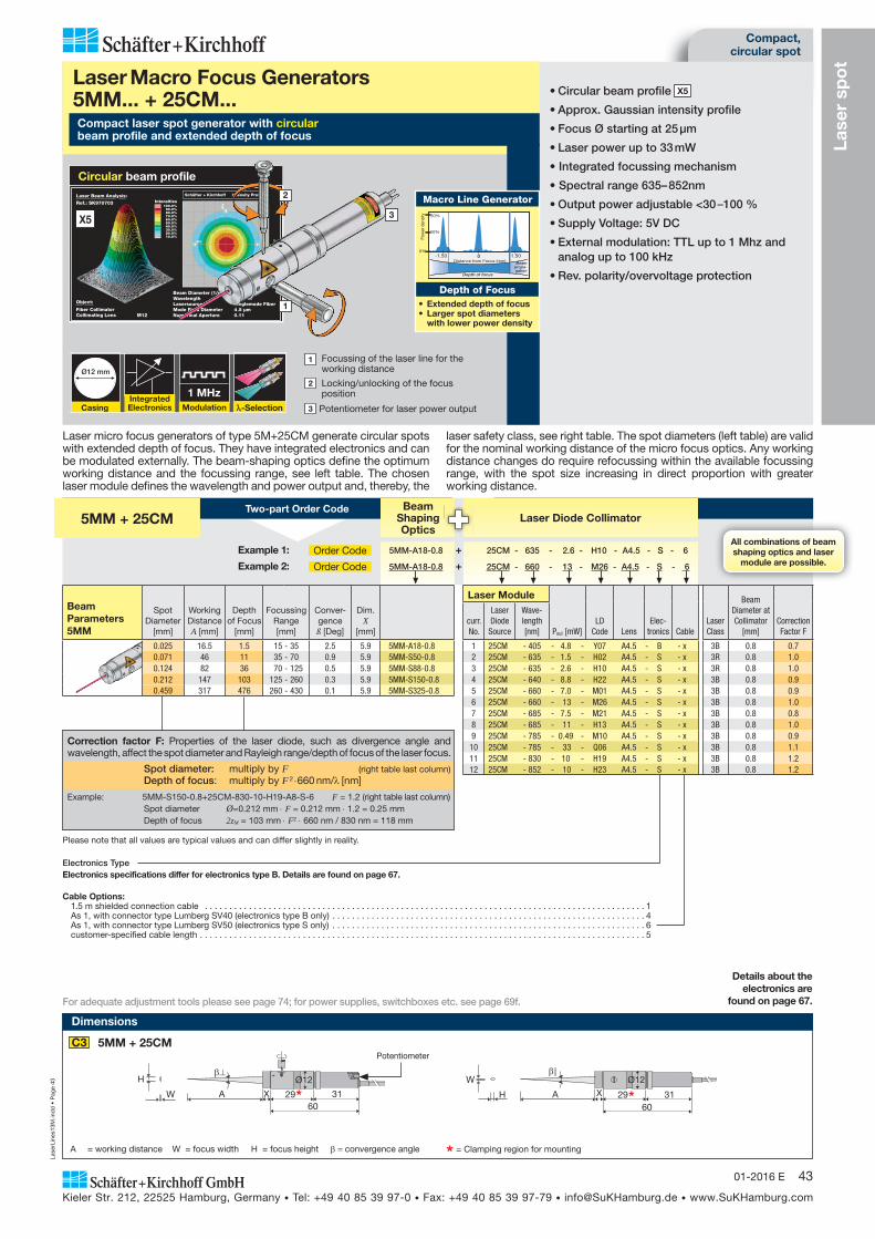
Lase
rLin
es13
M.in
dd
• P
age
43
Kieler Str. 212, 22525 Hamburg, Germany • Tel: +49 40 85 39 97-0 • Fax: +49 40 85 39 97-79 • [email protected] • www.SuKHamburg.com
4301-2016 E
Correction factor F: Properties of the laser diode, such as divergence angle and wavelength, affect the spot diameter and Rayleigh range/depth of focus of the laser focus.
Spot diameter: multiply by F (right table last column) Depth of focus: multiply by F 2 660 nm/ [nm]
Example: 5MM-S150-0.8+25CM-830-10-H19-A8-S-6 F = 1.2 (right table last column) Spot diameter Ø=0.212 mm F = 0.212 mm 1.2 = 0.25 mm Depth of focus 2zM = 103 mm F2 660 nm / 830 nm = 118 mm
Compact, circular spot
Lase
r sp
ot
Schäfter + Kirchhoff Intensity ProfileLaser Beam Analysis:
Ref.: SK970703 Intensities100.0%90.0%80.0%70.0%60.0%50.0%40.0%30.0%20.0%10.0%
Object:
Fiber CollimatorCollimating Lens M12
Beam Diameter (1/e2) 2.18 mmWavelength 635 nmLasersource Singlemode FiberMode Field Diameter 4.5 μmNumerical Aperture 0.11
Circular beam profile
Details about the electronics are
found on page 67.
Integrated Electronics
1 MHzModulation
Ø12 mm
Casing -Selection
Compact laser spot generator with circular beam profile and extended depth of focus
Laser Macro Focus Generators 5MM... + 25CM...
1 Focussing of the laser line for the working distance
2 Locking/unlocking of the focus position
3 Potentiometer for laser power output
• Circular beam profile X5
• Approx. Gaussian intensity profile
• Focus Ø starting at 25 μm
• Laser power up to 33 mW
• Integrated focussing mechanism
• Spectral range 635– 852nm
• Output power adjustable <30 –100 %
• Supply Voltage: 5V DC
• External modulation: TTL up to 1 Mhz and analog up to 100 kHz
• Rev. polarity/overvoltage protection
Laser micro focus generators of type 5M+25CM generate circular spots with extended depth of focus. They have integrated electronics and can be modulated externally. The beam-shaping optics define the optimum working distance and the focussing range, see left table. The chosen laser module defines the wavelength and power output and, thereby, the
laser safety class, see right table. The spot diameters (left table) are valid for the nominal working distance of the micro focus optics. Any working distance changes do require refocussing within the available focussing range, with the spot size increasing in direct proportion with greater working distance.
0%
10%
20%
0 1.50-1.50
Depth of focus
Pow
er d
ensi
ty
Distance from Focus (mm) Beampropa-gation
Macro Line Generator
Depth of Focus• Extended depth of focus• Larger spot diameters
with lower power density
All combinations of beamshaping optics and laser
module are possible.
BeamShapingOptics
Laser Diode Collimator 5MM + 25CMTwo-part Order Code
Example 1: Order Code 5MM-A18-0.8 + 25CM - 635 - 2.6 - H10 - A4.5 - S - 6
Example 2: Order Code 5MM-A18-0.8 + 25CM - 660 - 13 - M26 - A4.5 - S - 6
For adequate adjustment tools please see page 74; for power supplies, switchboxes etc. see page 69f.
BeamParameters5MM
Spot Diameter
[mm]
Working Distance A [mm]
Depth of Focus
[mm]
Focussing Range [mm]
Conver- gence ß [Deg]
Dim. X
[mm]
0.025 16.5 1.5 15 - 35 2.5 5.9 5MM-A18-0.8 0.071 46 11 35 - 70 0.9 5.9 5MM-S50-0.8 0.124 82 36 70 - 125 0.5 5.9 5MM-S88-0.8 0.212 147 103 125 - 260 0.3 5.9 5MM-S150-0.8 0.459 317 476 260 - 430 0.1 5.9 5MM-S325-0.8
Laser Module
Pout [mW]LD
Code LensElec-
tronics CableLaser Class
Beam Diameter at Collimator
[mm]Correction Factor F
curr.No.
Laser Diode Source
Wave-length [nm]
1 25CM - 405 - 4.8 - Y07 A4.5 - B - x 3B 0.8 0.7 2 25CM - 635 - 1.5 - H02 A4.5 - S - x 3R 0.8 1.0 3 25CM - 635 - 2.6 - H10 A4.5 - S - x 3R 0.8 1.0 4 25CM - 640 - 8.8 - H22 A4.5 - S - x 3B 0.8 0.9 5 25CM - 660 - 7.0 - M01 A4.5 - S - x 3B 0.8 0.9 6 25CM - 660 - 13 - M26 A4.5 - S - x 3B 0.8 1.0 7 25CM - 685 - 7.5 - M21 A4.5 - S - x 3B 0.8 0.8 8 25CM - 685 - 11 - H13 A4.5 - S - x 3B 0.8 1.0 9 25CM - 785 - 0.49 - M10 A4.5 - S - x 3B 0.8 0.9
10 25CM - 785 - 33 - Q06 A4.5 - S - x 3B 0.8 1.1 11 25CM - 830 - 10 - H19 A4.5 - S - x 3B 0.8 1.2 12 25CM - 852 - 10 - H23 A4.5 - S - x 3B 0.8 1.2
Cable Options:1.5 m shielded connection cable . . . . . . . . . . . . . . . . . . . . . . . . . . . . . . . . . . . . . . . . . . . . . . . . . . . . . . . . . . . . . . . . . . . . . . . . . . . . . . . . . . . . . . . . . . 1As 1, with connector type Lumberg SV40 (electronics type B only) . . . . . . . . . . . . . . . . . . . . . . . . . . . . . . . . . . . . . . . . . . . . . . . . . . . . . . . . . . . . . . . . 4As 1, with connector type Lumberg SV50 (electronics type S only) . . . . . . . . . . . . . . . . . . . . . . . . . . . . . . . . . . . . . . . . . . . . . . . . . . . . . . . . . . . . . . . . 6customer-specified cable length . . . . . . . . . . . . . . . . . . . . . . . . . . . . . . . . . . . . . . . . . . . . . . . . . . . . . . . . . . . . . . . . . . . . . . . . . . . . . . . . . . . . . . . . . . . 5
Electronics TypeElectronics specifications differ for electronics type B. Details are found on page 67.
3
2
1
X5
Dimensions
* = Clamping region for mountingA = working distance W = focus width H = focus height convergence angle
X60
31AW
H Ø12
29 X 2960
31A
Ø12
H
W
C3Potentiometer
5MM + 25CM
Please note that all values are typical values and can differ slightly in reality.
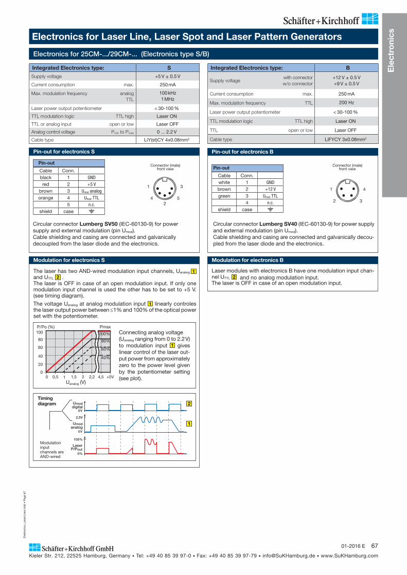
Ele
ktro
nics
_Las
erLi
nes.
ind
d •
Pag
e 67
Kieler Str. 212, 22525 Hamburg, Germany • Tel: +49 40 85 39 97-0 • Fax: +49 40 85 39 97-79 • [email protected] • www.SuKHamburg.com
6701-2016 E
Ele
ctro
nics
Pin-out
Circular connector Lumberg SV50 (IEC-60130-9) for power supply and external modulation (pin Umod).Cable shielding and casing are connected and galvanically decoupled from the laser diode and the electronics.
Cable Conn.black 1 GNDred 2 +5 V
brown 3 Umod analogorange 4 Umod TTL
5 n.c.shield case
Connector (male) front view
Electronics for Laser Line, Laser Spot and Laser Pattern Generators
Integrated Electronics type: S
Supply voltage +5 V ± 0.5 V
Current consumption max. 250 mA
Max. modulation frequency analog TTL
100 kHz1 MHz
Laser power output potentiometer < 30-100 %
TTL modulation logic TTL high Laser ON
TTL or analog input open or low Laser OFF
Analog control voltage Pmin to Pmax 0 ... 2.2 V
Cable type LiY(st)CY 4x0.08mm2
Integrated Electronics type: B
Supply voltage with connectorw/o connector
+12 V ± 0.5 V+9 V ± 0.5 V
Current consumption max. 250 mA
Max. modulation frequency TTL 200 Hz
Laser power output potentiometer < 30-100 %
TTL modulation logic TTL high Laser ON
TTL open or low Laser OFF
Cable type LiFYCY 3x0.08mm2
Pin-out
Circular connector Lumberg SV40 (IEC-60130-9) for power supply and external modulation (pin Umod).Cable shielding and casing are connected and galvanically decou-pled from the laser diode and the electronics.
Cable Conn.white 1 GNDbrown 2 +12 Vgreen 3 Umod TTL
4 n.c.shield case
100
80
60
40
20
0
Uanalog (V)
P/Po (%)
0 0,5 1 1,5 2 2,2 4,5 +5V
Pmax
80%
60%
40%
100% Connecting analog voltage (Uanalog ranging from 0 to 2.2 V) to modulation input 1 gives linear control of the laser out-put power from ap proximately zero to the power level given by the potentiometer setting (see plot).
Umoddigital
0V
Umodanalog
2,5V
0V
LaserP/Pout
100%
0%
Timing diagram 2
1
Modulation input channels are AND-wired
Modulation for electronics S
The laser has two AND-wired modulation input channels, Uanalog 1 and UTTL 2 .The laser is OFF in case of an open modulation input. If only one modulation input channel is used the other has to be set to +5 V. (see timing diagram).
The voltage Uanalog at analog modulation input 1 linearly controles the laser output power between 1% and 100% of the optical power set with the potentiometer.
Modulation for electronics B
Laser modules with electronics B have one modulation input chan-nel UTTL 2 and no analog modulation input.The laser is OFF in case of an open modulation input.
Electronics for 25CM-.../29CM-... (Electronics type S/B)
Pin-out for electronics S Pin-out for electronics B
3
5
1
42
Connector (male) front view
4
3
1
2
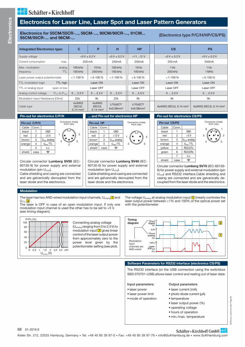
Ele
ktro
nics
_Las
erLi
nes.
ind
d •
Pag
e 68
Kieler Str. 212, 22525 Hamburg, Germany • Tel: +49 40 85 39 97-0 • Fax: +49 40 85 39 97-79 • [email protected] • www.SuKHamburg.com
68 01-2016 E
Ele
ctro
nics
Electronics for 55CM/55CR-..., 56CM-..., 90CM/90CR-..., 91CM...95CM/95CR-... and 96CM-...
Integrated Electronics type: C P H HP CS PS
Supply voltage +5 V ± 0.2 V +5 V ± 0.2 V +11...12 V +5 V ± 0.2 V +5 V ± 0.2 V
Current consumption max. 250 mA 250mA 250mA 250 mA 250mA
Max. modulation frequency
analog TTL
100 kHz 100 kHz
10 Hz 250 kHz
100 kHz 100 kHz
10 Hz 100 kHz
1 Hz 250 kHz
1 Hz 1 MHz
Laser power output potentiometer < 1-100 % < 5-100 % < 1-100 % < 5-100 % < 1-100 % < 5-100 %
TTL modulation logic TTL high Laser ON Laser ON Laser ON Laser ON
TTL or analog input open or low Laser OFF Laser OFF Laser OFF Laser OFF
Analog control voltage Pmin to Pmax 0 ... 2.5 V 0 ... 2.5 V 0 ... 2.5 V 0 ... 2.5 V 0 ... 2.5 V 0 ... 2.5 V
Modulation Input Resistance [Ohm] 22k 9k 22k 9k 9k 9k
Cable type4xAWG 26CUL
0.14 mm2
4xAWG 26CUL
0.14 mm2
LiY(st)CY 4x0.08mm2
LiY(st)CY 4x0.08mm2
6xAWG 26CUL 0.14 mm2 6xAWG 26CUL 0.14 mm2
Pin-out C/P/H
Cable Conn.black 1 GNDred 2 +5 V
brown 3 Umod analogorange 4 Umod TTL
5 n.c.shield case
Circular connector Lumberg SV50 (IEC-60130-9) for power supply and external modulation (pin Umod).Cable shielding and casing are connected and are galvanically decoupled from the laser diode and the electronics.
Pin-out CS/PS
Cable Conn.black 1 GNDred 2 +5 V
brown 3 Umod analogorange 4 Umod TTLyellow 5 RS232Txgreen 6 RS232Rx
7 n.c.shield case
Circular connector Lumberg SV70 (IEC-60130-9) for power supply and external modulation (pin Umod) and RS232 interface.Cable shielding and casing are connected and are galvanically de-coupled from the laser diode and the electronics.
Connecting analog voltage (Uanalog ranging from 0 to 2.5 V) to modulation input 1 gives linear control of the laser output power from ap proximately zero to the power level given by the potentiometer setting (see plot).
The laser has two AND-wired modulation input channels, Uanalog 1 and UTTL 2 .The laser is OFF in case of an open modulation input. If only one modulation input channel is used the other has to be set to +5 V. (see timing diagram).
The voltage Uanalog at analog modulation input 1 linearly controles the laser output power between 1% and 100% of the optical power set with the potentiometer.
100
80
60
40
20
0
Uanalog (V)
P/Po (%)
0 0,5 1 1,5 2 2,5 4,5 +5V
Umoddigital
0V
Umodanalog
2,5V
0V
LaserP/Pout
100%
0%
Timing diagram 2
1
Modulation input channels are AND-wired
Electronics for Laser Line, Laser Spot and Laser Pattern Generators
(Electronics type P/C/H/HP/CS/PS)
Connector (male) front view
3
5
1
42
Connector (male) front view
1
2
34
5
6
7
Input parameters:
• laser power• laser power limit• mode of operation
Output parameters
• laser current (mA)• photo diode current (μA)• temperature• laser output power (%)• operating voltage• hours of operation• min./max. temperature
The RS232 interface (or the USB connection using the switchbox SBS 070701-USB) allows laser control and reating out of laser data:
Pin-out for electronics C/P/H Pin-out for electronics CS/PS
Modulation
Software Parameters for RS232 interface (electronics CS/PS)
Pin-out HP
Cable Conn.black 1 GNDred 2 +12 V
brown 3 Umod analogorange 4 Umod TTLshield case
Circular connector Lumberg SV40 (IEC-60130-9) for power supply and external modulation (pin Umod).Cable shielding and casing are connected and are galvanically decoupled from the laser diode and the electronics.
... and Pin-out for electronics HP
Connector (male) front view
4
3
1
2
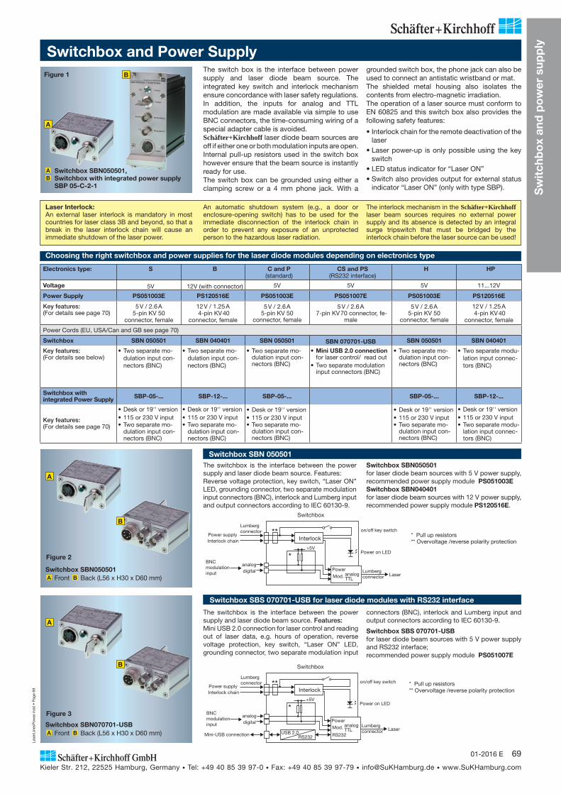
Switchbox SBS 070701-USB for laser diode modules with RS232 interface
The switchbox is the interface between the power supply and laser diode beam source. Features:Mini USB 2.0 connection for laser control and reading out of laser data, e.g. hours of operation, reverse voltage protection, key switch, “Laser ON” LED, grounding connector, two separate modulation input
connectors (BNC), interlock and Lumberg input and output connectors according to IEC 60130-9.
Switchbox SBS 070701-USBfor laser diode beam sources with 5 V power supply and RS232 interface;recommended power supply module PS051007E
* Pull up resistors** Overvoltage /reverse polarity protection
Switchbox SBN070701-USBA Front B Back (L56 x H30 x D60 mm)
Figure 3
A
B
Lase
rLin
esP
ower
.ind
d •
Pag
e 69
Kieler Str. 212, 22525 Hamburg, Germany • Tel: +49 40 85 39 97-0 • Fax: +49 40 85 39 97-79 • [email protected] • www.SuKHamburg.com
6901-2016 E
Switchbox and Power SupplyThe switch box is the interface between power supply and laser diode beam source. The integrated key switch and interlock mechanism ensure concordance with laser safety regulations. In addition, the inputs for analog and TTL modulation are made available via simple to use BNC connectors, the time-consuming wiring of a special adapter cable is avoided.Schäfter+Kirchhoff laser diode beam sources are off if either one or both modulation inputs are open. Internal pull-up resistors used in the switch box however ensure that the beam source is instantly ready for use.The switch box can be grounded using either a clamping screw or a 4 mm phone jack. With a
A Switchbox SBN050501,B Switchbox with integrated power supply
SBP 05-C-2-1
Laser Interlock: An external laser interlock is mandatory in most countries for laser class 3B and beyond, so that a break in the laser interlock chain will cause an immediate shutdown of the laser power.
An automatic shutdown system (e.g., a door or enclosure-opening switch) has to be used for the immediate disconnection of the interlock chain in order to prevent any exposure of an unprotected person to the hazardous laser radiation.
The interlock mechanism in the Schäfter+Kirchhoff laser beam sources requires no external power supply and its absence is detected by an integral surge tripswitch that must be bridged by the interlock chain before the laser source can be used!
Figure 1
A
B
Switchbox SBN 050501The switchbox is the interface between the power supply and laser diode beam source. Features:Reverse voltage protection, key switch, “Laser ON” LED, grounding connector, two separate modulation input connectors (BNC), interlock and Lumberg input and output connectors according to IEC 60130-9.
Switchbox SBN050501A Front B Back (L56 x H30 x D60 mm)
Figure 2
A
B
Switchbox SBN050501 for laser diode beam sources with 5 V power supply, recommended power supply module PS051003ESwitchbox SBN040401for laser diode beam sources with 12 V power supply, recommended power supply module PS120516E.
grounded switch box, the phone jack can also be used to connect an antistatic wristband or mat.The shielded metal housing also isolates the contents from electro-magnetic irradiation. The operation of a laser source must conform to EN 60825 and this switch box also provides the following safety features:
• Interlock chain for the remote deactivation of the laser
• Laser power-up is only possible using the key switch
• LED status indicator for “Laser ON”• Switch also provides output for external status
indicator “Laser ON” (only with type SBP).
BNC modulationinput
on/off key switch
Power on LED
Lumberg connector
Lumberg connector
Power supply
Switchbox
LaserMini-USB connection
Interlock
RS232USB 2.0
Poweranalogdigital
Interlock chain
+5V
*
**
TTLRS232
Mod. analog
BNC modulationinput
on/off key switch
Power on LED
Lumberg connector
Lumberg connector
Power supply
Switchbox
Laser
Interlock
Poweranalogdigital
Interlock chain
+5V
*
**
TTLMod. analog
* Pull up resistors** Overvoltage /reverse polarity protection
Choosing the right switchbox and power supplies for the laser diode modules depending on electronics type
Electronics type: S B C and P(standard)
CS and PS(RS232 interface)
H HP
Voltage 5V 12V (with connector) 5V 5V 5V 11...12V
Power Supply PS051003E PS120516E PS051003E PS051007E PS051003E PS120516E
Key features:(For details see page 70)
5 V / 2.6 A5-pin KV 50
connector, female
12 V / 1.25 A 4-pin KV 40
connector, female
5 V / 2.6 A5-pin KV 50
connector, female
5 V / 2.6 A 7-pin KV 70 connector, fe-
male
5 V / 2.6 A5-pin KV 50
connector, female
12 V / 1.25 A 4-pin KV 40
connector, female
Power Cords (EU, USA/Can and GB see page 70)
Switchbox SBN 050501 SBN 040401 SBN 050501 SBN 070701-USB SBN 050501 SBN 040401
Key features:(For details see below)
• Two separate mo-dulation input con-nectors (BNC)
• Two separate mo-dulation input con-nectors (BNC)
• Two separate mo-dulation input con-nectors (BNC)
• Mini USB 2.0 connection for laser control/ read out
• Two separate modulation input connectors (BNC)
• Two separate mo-dulation input con-nectors (BNC)
• Two separate modu-lation input connec-tors (BNC)
Switchbox with integrated Power Supply SBP-05-... SBP-12-... SBP-05-... SBP-05-... SBP-12-...
Key features:(For details see page 70)
• Desk or 19'' version• 115 or 230 V input• Two separate mo-
dulation input con-nectors (BNC)
• Desk or 19'' version• 115 or 230 V input• Two separate mo-
dulation input con-nectors (BNC)
• Desk or 19'' version• 115 or 230 V input• Two separate mo-
dulation input con-nectors (BNC)
• Desk or 19'' version• 115 or 230 V input• Two separate mo-
dulation input con-nectors (BNC)
• Desk or 19'' version• 115 or 230 V input• Two separate modu-
lation input connec-tors (BNC)
Sw
itch
bo
x an
d p
ow
er s
upp
ly
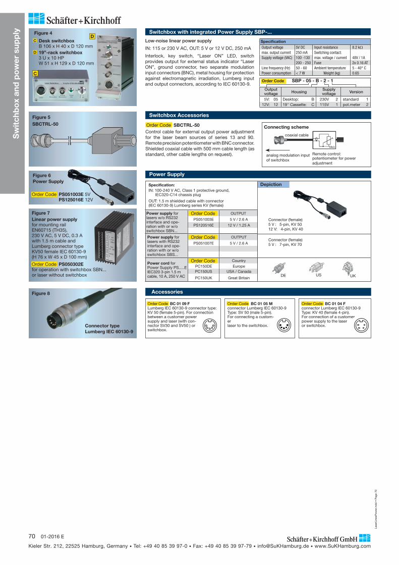
Lase
rLin
esP
ower
.ind
d •
Pag
e 70
Kieler Str. 212, 22525 Hamburg, Germany • Tel: +49 40 85 39 97-0 • Fax: +49 40 85 39 97-79 • [email protected] • www.SuKHamburg.com
70 01-2016 E
Accessories
Order Code BC 01 09 FLumberg IEC 60130-9 connector type: KV 50 (female 5-pin). For connection between a customer power supply and laser (with con-nector SV30 and SV50 ) or switchbox.
Order Code BC 01 04 Fconnector Lumberg IEC 60130-9 Type: KV 40 (female 4-pin). For connection of a customer power supply to the laser or switchbox.
Order Code BC 01 05 Mconnector Lumberg IEC 60130-9 Type: SV 50 (male 5-pin). For connecting a custom-er laser to the switchbox.
Figure 6Power Supply
Figure 7
Figure 8
Linear power supply for mounting rail EN60715 (TH35), 230 V AC, 5 V DC, 0.3 A with 1.5 m cable and Lumberg connector type KV50 female IEC 60130-9 (H 76 x W 45 x D 100 mm)
Connector type Lumberg IEC 60130-9
Specification:IN: 100-240 V AC, Class 1 protective ground, IEC320-C14 chassis plug
OUT: 1.5 m shielded cable with connector (IEC 60130-9) Lumberg series KV (female)
Depiction
Connector (female)5 V : 5-pin, KV 5012 V: 4-pin, KV 40
DE US UK
Power Supply
Order Code PS050302E for operation with switchbox SBN... or laser without switchbox
Order Code PS051003E 5V PS125016E 12V
Connector (female)5 V : 7-pin, KV 70
Power supply for lasers w/o RS232 interface and ope-ration with or w/o switchbox SBN...
Order Code OUTPUT
PS051003E 5 V / 2.6 A
PS120516E 12 V / 1.25 A
Power supply for lasers with RS232 interface and ope-ration with or w/o switchbox SBS...
Order Code OUTPUT
PS051007E 5 V / 2.6 A
Power cord for Power Supply PS.....EIEC320 3-pin 1.5 m cable, 10 A, 250 V AC
Order Code CountryPC150DE EuropePC150US USA / Canada
PC150UK Great Britain
Figure 5SBCTRL-50 Order Code SBCTRL-50
Control cable for external output power adjustment for the laser beam sources of series 13 and 90. Remote precision potentiometer with BNC connector. Shielded coaxial cable with 500 mm cable length (as standard, other cable lengths on request).
Switchbox Accessories
coaxial cable
analog modulation input of switchbox
Remote control: potentiometer for power adjustment
Connecting scheme
10k
Switchbox with integrated Power Supply SBP-...
Low-noise linear power supply
IN: 115 or 230 V AC, OUT: 5 V or 12 V DC, 250 mA
Interlock, key switch, “Laser ON” LED, switch provides out put for external status indicator “Laser ON”, ground connector, two separate modulation input connectors (BNC), metal housing for protection against electromagnetic irradiation, Lumberg input and output connectors, according to IEC 60130-9.
C Desk switchbox B 106 x H 40 x D 120 mm
D 19’’-rack switchbox 3 U x 10 HP W 51 x H 129 x D 120 mm
Figure 4
C
DSpecificationOutput voltage 5V DC Input resistance 8.2 kmax. output current 250 mA Switching contact:Supply voltage (VAC) 100 -130 max. voltage / current 48V / 1A
200 - 250 Fuse 2x 0.16 ATLine frequency (Hz) 50 - 60 Ambient temperature 5 - 40° CPower consumption < 7 W Weight (kg) 0.65
Order Code SBP - 05 - B - 2 - 1
Output voltage Housing
Supply voltage Version
5V: 05 Desktop: B 230V 2 standard 112V: 12 19'' Cassette: C 115V 1 pot.meter 2
Sw
itch
bo
x an
d p
ow
er s
upp
ly
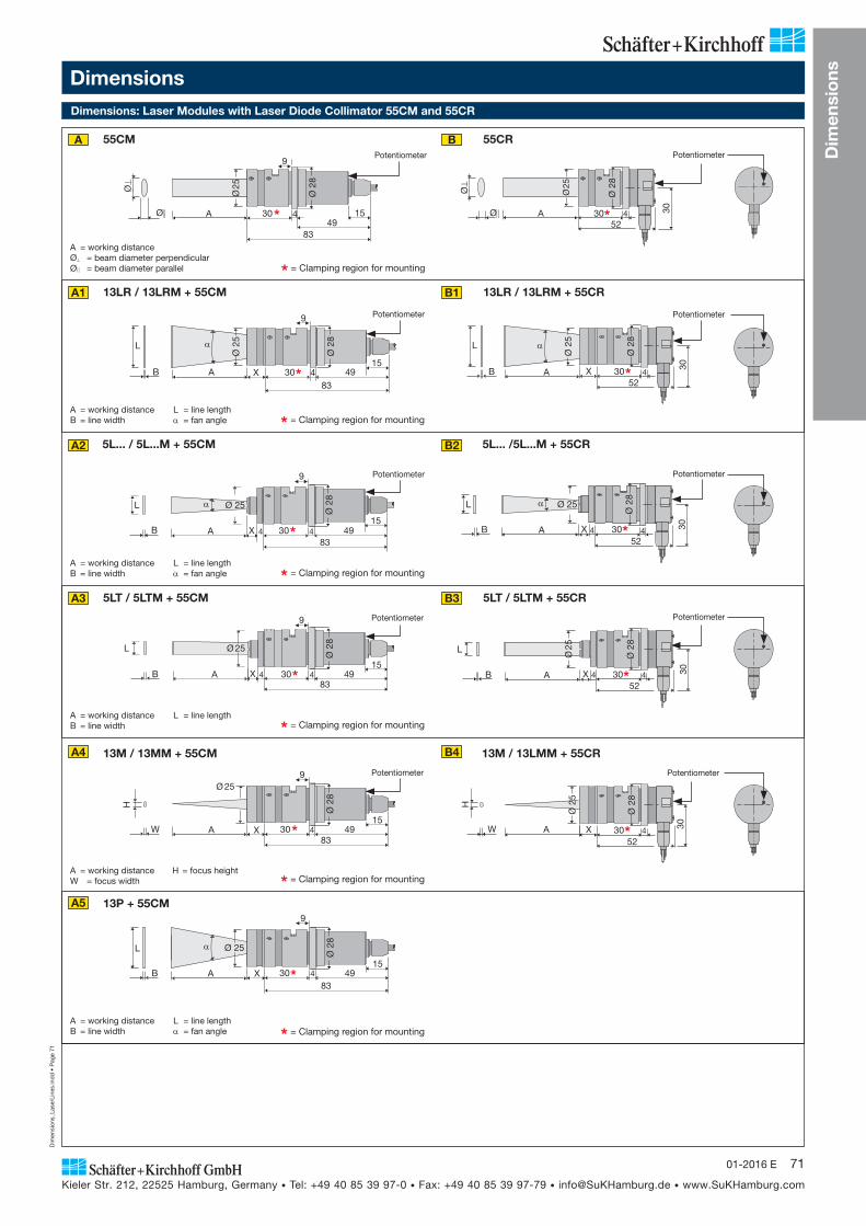
Dim
ensi
ons_
Lase
rLin
es.in
dd
• P
age
71
Kieler Str. 212, 22525 Hamburg, Germany • Tel: +49 40 85 39 97-0 • Fax: +49 40 85 39 97-79 • [email protected] • www.SuKHamburg.com
7101-2016 E
5L... / 5L...M + 55CM 5L... /5L...M + 55CR
Dim
ensi
ons
83
30 449
15
9
Ø
Ø
Ø 2
8
Ø 2
5
A
3052
4 30
X
Ø 2
8
Ø 2
5
AB
L
AB
L
X83
30 4 4915
9Ø
28
Ø 2
5
AB
L
3052
4 30
X 4
Ø 2
8
Ø 25
AB
L
X83
30 4 4915
9
Ø 25
Ø 2
8
4
X83
30 4 4915
9
AB
L
Ø 2
8
Ø 25
3052
4 30
X 4
Ø 2
8
Ø 2
5
AB
L
3052
4 30
XW
H
Ø 2
5
Ø 2
8
AW
H
X83
30 4 4915
9Ø 25
A
Ø 2
8
AB
L
8330 4 49
15
9
X
Ø 25
Ø 2
8
4
Ø 3052
4 30
Ø 2
8
Ø 2
5
A
Ø
13P + 55CM
13LR / 13LRM + 55CM 13LR / 13LRM + 55CR
Dimensions
A = working distanceB = line width
L = line length = fan angle
Dimensions: Laser Modules with Laser Diode Collimator 55CM and 55CR
* = Clamping region for mounting
* = Clamping region for mounting
A = working distanceB = line width
L = line length = fan angle
5LT / 5LTM + 55CM 5LT / 5LTM + 55CR
A = working distanceB = line width
L = line length
* = Clamping region for mounting
A = working distanceW = focus width * = Clamping region for mounting
A = working distanceØ = beam diameter perpendicularØ = beam diameter parallel * = Clamping region for mounting
A = working distanceB = line width
L = line length = fan angle * = Clamping region for mounting
A B
A1 B1
A2 B2
A3 B3
A4 B4
A5
Potentiometer
Potentiometer
Potentiometer
Potentiometer
13M / 13MM + 55CM 13M / 13LMM + 55CR
Potentiometer
Potentiometer
Potentiometer
Potentiometer
Potentiometer Potentiometer
55CM 55CR
H = focus height
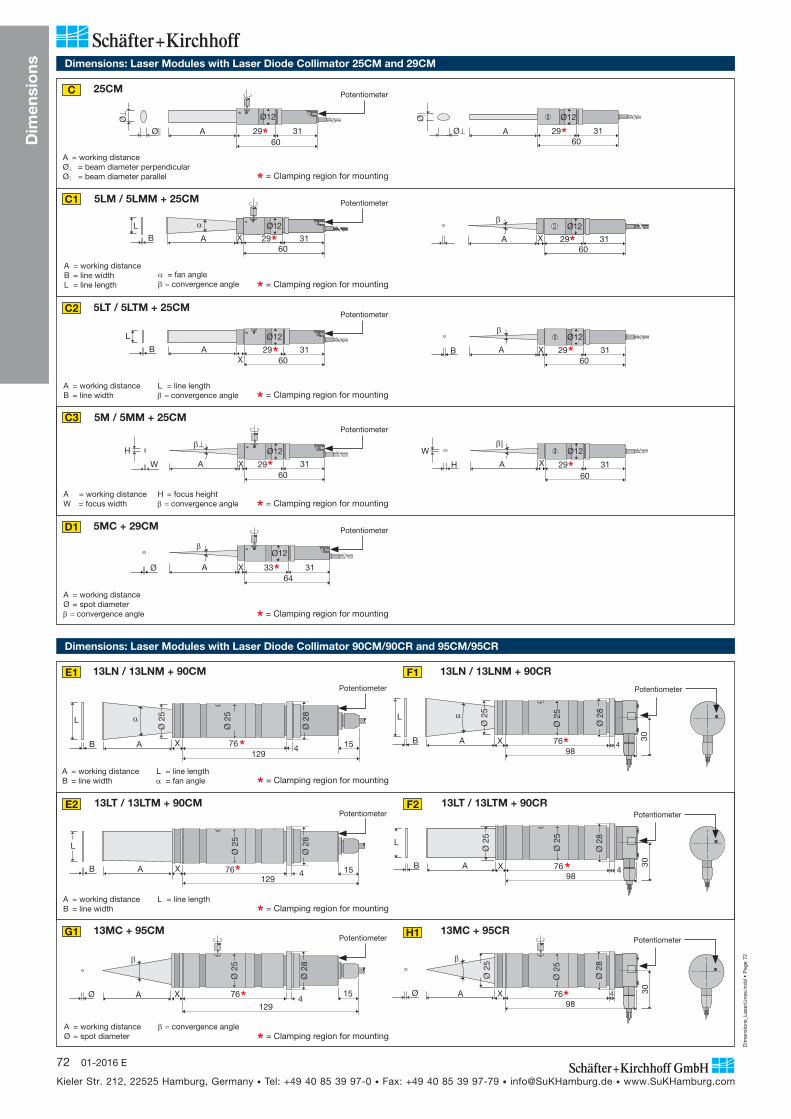
Dim
ensi
ons_
Lase
rLin
es.in
dd
• P
age
72
Kieler Str. 212, 22525 Hamburg, Germany • Tel: +49 40 85 39 97-0 • Fax: +49 40 85 39 97-79 • [email protected] • www.SuKHamburg.com
72 01-2016 E
Dim
ensi
ons
X 2960
31ABL Ø12
2960
31AØ
Ø
Ø12
X60
31AW
H Ø12
29
X 3364
31A
Ø12
Ø
X29
6031AB
Ø12L
X 2960
31A
Ø12
H
W
2960
31AØ
Ø Ø12
X 2960
31A
Ø12
X 2960
31AB
Ø12
5MC + 29CM
A = working distanceØ = spot diameter
convergence angle
5M / 5MM + 25CM
Dimensions: Laser Modules with Laser Diode Collimator 90CM/90CR and 95CM/95CR
Dimensions: Laser Modules with Laser Diode Collimator 25CM and 29CM
5LM / 5LMM + 25CM
25CM
A = working distanceØ = beam diameter perpendicularØ = beam diameter parallel
5LT / 5LTM + 25CM
C
C1
C2
C3
D1
13LN / 13LNM + 90CM 13LN / 13LNM + 90CR
15476
129XAB
L
Ø 2
8
Ø 2
5
Ø 2
5
30
AB
L
47698
X
Ø 2
5
Ø 2
5
Ø 2
8
A = working distanceB = line width
L = line length = fan angle
E1 F1
13MC + 95CM 13MC + 95CR
A = working distanceØ = spot diameter
convergence angle
G1 H1
13LT / 13LTM + 90CM 13LT / 13LTM + 90CR
A = working distanceB = line width
L = line length
E2 F2
* = Clamping region for mounting
A = working distanceB = line width
L = line lengthconvergence angle * = Clamping region for mounting
A = working distanceW = focus width
H = focus heightconvergence angle * = Clamping region for mounting
* = Clamping region for mounting
A = working distanceB = line widthL = line length
= fan angleconvergence angle * = Clamping region for mounting
Potentiometer
Potentiometer
Potentiometer
Potentiometer
Potentiometer
AB
L
47698
X
Ø 2
8
Ø 2
5
30
Ø 2
5
AB
L
15476X129
Ø 2
5
Ø 2
8
15476
129
XAØ
Ø 2
8
Ø 2
5
Ø 30
47698
X
Ø 2
5
Ø 2
5
Ø 2
8
A
Potentiometer
Potentiometer
Potentiometer
Potentiometer
Potentiometer
Potentiometer
* = Clamping region for mounting
* = Clamping region for mounting
* = Clamping region for mounting
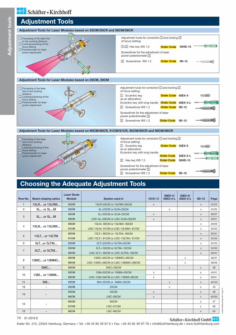
Lase
rLin
esM
ount
ing.
ind
d •
Pag
e 74
Kieler Str. 212, 22525 Hamburg, Germany • Tel: +49 40 85 39 97-0 • Fax: +49 40 85 39 97-79 • [email protected] • www.SuKHamburg.com
74 01-2016 E
Row No. Beam-shaping opticsLaser Diode
Module System used in 50HD-1560EX-4/
60EX-4-L55EX-5/
55EX-5-L 9D-12 Page
1 13LR... or 13LRM... 55CM 13LR+55CM or 13LRM+55CM x x 22/23
2 5L... or 5L...M 25CM 5L+25CM or 5LM+25CM x x 24/25
3 5L... or 5L...M55CM 5L+55CM or 5LM+55CM x x 26/27
56CM LNC-5L+56CM or LNC-5LM+56CM x x 50/51
4 13LN... or 13LNM...90CM 13LN+ 90CM or 13LNM+ 90CM x 28/29
91CM LNC-13LN+ 91CM or LNC-13LNM+ 91CM x 52/53
5 13LT... or 13LTM90CM 13LT+ 90CM or 13LTM+ 90CM x 30/31
91CM LNC-13LT+ 91CM or LNC-13LTM+ 91CM x 54/55
6 5LT...or 5LTM... 25CM 5LT+25CM or 5LTM+25CM x 32/33
7 5LT... or 5LTM...55CM 5LT+ 55CM or 5LTM+ 55CM x 34/35
56CM LNC-5LT+ 56CM or LNC-5LTM+ 56CM x 56/57
8 13MC... or 13MMC...95CM 13MC+95CM or 13MMC+95CM x 36/37
96CM LNC-13MC+96CM or LNC-13MMC+96CM x 58/59
9 5MC... 29CM 5MC+29CM x x 38
10 13M... or 13MM...55CM 13M+55CM or 13MM+55CM x x 40/41
56CM LNC-13M+56CM or LNC-13MM+56CM x x 60/61
11 5M... 25CM 5M+25CM or 5MM+25CM x x 42/43
12 - 25CM 25CM x x 45
13 -55CM 55CM x x 46
56CM LNC-56CM x x 62/63
14 -90CM 90CM x 47
91CM LNC-91CM x 66
15 - 96CM LNC-96CM x 64
Ad
just
men
t to
ols
Adjustment Tools
Adjustment tools for correction 1 and locking 2 of focus setting:
1 + 2 Hex key WS 1.5 Order Code 50HD-15
Screwdriver for the adjustment of laser power potentiometer 3
3 Screwdriver WS 1.2 Order Code 9D-12
1 Focussing of the laser line to the working distance
2 Locking/unlocking of the focus setting 3 Potentiometer for laser
power adjustment
Adjustment Tools for Laser Modules based on 55CM/55CR and 56CM/56CR
Adjustment Tools for Laser Modules based on 25CM, 29CM
Adjustment tools for correction 1 and locking 2 of focus setting:
1 Eccentric key Order Code 60EX-4as an alternative:Eccentric key with long handle Order Code 60EX-4-L
2 Screwdriver WS 1.2 Order Code 9D-12
Screwdriver for the adjustment of laser power potentiometer 3
3 Screwdriver WS 1.2 Order Code 9D-12
1 Focussing of the laser line to the working distance
2 Locking/unlocking of the focus setting
3 Potentiometer for laser power adjustment
Adjustment tools for correction 1 and locking 2 of focus setting:1 Eccentric key Order Code 55EX-5as an alternative:Eccentric key with long handle Order Code 55EX-5-L
2 Hex key WS 1.5 Order Code 50HD-15
Screwdriver for the adjustment of laser power potentiometer 3
3 Screwdriver WS 1.2 Order Code 9D-12
1 Focussing of the laser line to the working distance
2 Locking/unlocking of the focus setting
3 Potentiometer for laser power adjustment
Adjustment Tools for Laser Modules based on 90CM/90CR, 91CM/91CR, 95CM/95CR and 96CM/96CR
2
1
3
2
1
1
2
3
3
Choosing the Adequate Adjustment Tools