

automated physics demonstrations controlled using visual basic

Physics Demonstrations Anveshika
National Anveshika Network of India (NANI)
Version 0.03, January 1, 2015

+ c©NOTICE: “This material is protected by copyright and has been copiedsolely for the non-commercial educational purposes. You may not sell, alter orfurther reproduce or distribute any part of this material to any other person.Where provided to you in electronic format, you may only print from it foryour own private study and research. Failure to comply with the terms ofthis warning may expose you to legal action for copyright infringement and/ordisciplinary action by the copyright holders of original work.”
+ ACKNOWLEDGMENT: Our sincere gratitude to,
(a) Dr H C Verma, Coordinator, National Anveshika Network of India(NANI). He is the driving force for Anveshika activities.
(b) Shiksha Sopan, IIT Kanpur
(c) Utsahi Physics Teachers, www.utsahiphysicsteachers.com
(d) Dr Ajay Mahajan, Dayanand Science College, Latur, Maharashtra
(e) Anveshika Coordinators and their team members:
Kanpur SGM Amit Kumar BajpayiAgra Raman R K AwasthiSiwan Siwan Mr. Rajeev RanjanKolkata TAXXILA Dr. Amit Kumar JanaLucknow Mitra Dr. R. K MitraPatna Patna Dr Amarendra NarayanOraiya Go&go Brajesh DixitMunger VSS Dr. K N RaiKolhapur GCG Dr S A MastiBhilkwadi SSB Dr Gajanan PatilPilibhit Samadhan Dr Laxmi Kant SharmaPilani BPS Mr Manoranjan K SinghHissar OPJS Lalit Mohan SinghDelhi BVN Pragya NopaniUdhampur Happy MineeshVizianagram Focus Chandrasekhar JogaChandigarh SGGSC Dr M S MarwahaDhanbad Vidya Arvind Kumar PathakHyderabad ViBha Jitender Singh
+ DISCLAIMER: Although most of the science activities presented here are re-garded as low hazard, we disclaim all liability for any occurrence, including,but not limited to, damage, injury or death which might arise as consequencesof the use of any experiment(s) listed or described here. Therefore, you assumeall the liability and use these science activities at your own risk!

Dedicated to those who appreciate Physics
and the work of Dr. H. C. Verma

Contents
Contents iii
I Mechanics 1
1 Measure Speed of the Ant 3
2 Reaction Time 4
3 How Much is One Newton? 5
4 Pull the Paper under the Tumbler 6
5 Balancing the Nails 7
6 A drop of Water Makes Slides Stick Together 8
7 Get Going Mug 9
8 Action-Reaction forces in Newtons Third Law 10
9 Check Newton’s Law for interaction between two RingMagnets 11
10 Resonance and Sound Waves 12
11 The Physics of Lever and Mechanical Advantage 13
12 Weightlessness with slinky 14
13 Which thread breaks first? 15
14 A Magical Coin 16
15 Lift a Weight by Moving another Weight in a Circle 17
16 Key-bottle experiment 18
17 Spring Potential Energy 19
18 Calibrating a Non-Linear Spring 20
Corrections/Suggestions to: [email protected] iii

iv Contents
19 Linear Momentum of the Ball 21
20 Why Does it Goes Up? 22
21 Counter-intutive Centre of Mass with Bottle 23
22 Balancing the Scale on Fingers 24
23 To find Centre of Mass of a Rectangular Shape 25
24 To Find the Coefficient of Restitution 26
25 It is not Easy to Do Simple Movements! 27
26 Win a 100 Rs Note 28
27 Self Balancing Toy 29
28 Rolling and Kinetic Friction 30
29 Gyroscope from cycle wheel 31
30 To study the theorem of perpendicular axes in Momentof Inertia 33
31 Paper Helicopter 34
32 Gyroscope Using Toy Motor 35
33 Coupled Pendulum 36
34 SHM Phase and Phase Difference 37
35 Resonance in pendulum by hand 39
36 To Study Torsional Oscillation of a Rectangular Body 40
37 Why Balloons come Closer? 41
38 Why the fluid does not comes out? 42
39 Suspending a Cup by a Balloon 43
40 Keep the Paper Dry in Water 44
41 Push Water in a pair of Connected Syringes 45
42 Blow Air in a Long Air Bag 46

Contents v
43 To find the atmospheric pressure using a syringe andweights 47
44 To measure the viscosity of water 48
45 Archimedes Principle 49
46 Effect of Soap on Surface Tension 50
47 Rise of Paper (Welcome) due to surface tension 51
48 Pressure in Two Balloons connected by transparent pipe 52
49 The Fun of Three Bottles 53
50 Rising of water due to centrifugal force! 54
51 To study the extension-load characteristics of bicyclevalve tube 55
52 To study torsional oscillations of a wire 56
II Waves 57
53 Vibrations, Rerefaction and Compression in a Long Spring! 59
54 Visualize Wave Motion 60
55 Compression and Rarefaction in Longitudinal Waves 61
56 Sound is Produced by Vibrations 62
57 Reflection of Sound 63
58 Visualize your Sound! 64
59 The Phenomenon of Beats! 65
60 The Optics of Waves on Water Surface 66
61 Interference with thread! 67
62 Diffraction of light from a thin wire! 68
63 Interference in Ripple Tank! 69

vi Contents
IIIOptics 71
64 Multiple Images with Plane Mirrors 73
65 Scattering of Lights of Different Colours 74
66 Scattering of Light 75
67 Dispersion of Light by a Prism 76
68 Tracing the Ray of Light through a Prism? 77
69 Advantage of having Two Eyes? 78
70 Image formed by a Convex Lens 79
71 Reflection from Curved Surface 80
72 Focal Length of a Concave Mirror 81
73 Nature of the Image formed by a Concave Mirror 82
74 Rising of the Coin due to Refraction 83
75 Refraction through a Glass Slab 84
76 Trace the Path of a Ray through Glass Slab 85
77 Refraction Through a Glass of Water 86
78 Measuring the Focal Length of a Convex Lens 87
79 Total Internal Reflection in a Dettol Bottle 88
80 Focal Length of a Parabolic Reflector! 90
81 Laws of Reflection of Light! 91
82 To Deduce Refractive Index of a Glass Slab 92
83 To Visualize a Light Ray 93
84 To Find Focal Length of a Concave Lens 94
85 To Find Refractive Index of a Liquid 95
86 To study the variation of image position for object atinfinity with incident angle 96

Contents vii
87 Where did the Coin come from? 97
88 Polarization of Light! 98
89 Variation of refractive index with wavelength 99
90 Variation of Intensity with Distance! 100
IVThermodynamics 101
91 Burning Candle in Limited Air 103
92 Why Does Water not Fall? 104
93 Own Thermometer 106
94 Saturated Salt Solution 107
95 Why does Water rise in Burning Candle Experiment? 108
96 Boyles law using a syringe and weights 110
97 Boil Water with Hands! 111
98 Cloud in a Bottle! 113
99 Measure dew point in your room 114
100 Coffee cup calorimetry 115
101 See Convection Current in Air 116
102 Conduction of Heat 117
103 Solar Heating 118
104 Boiling Water in Paper Cup 119
V Electromagnetism 121
105 The Rotating Straw 123
106 Bending of Water Stream due to Electrostatic Charges 125
107 Electrostatics of Hanging Balloons 126
108 Which Direction is Electric Field? 127

viii Contents
109 Direction of electric field 128
110 Electric potential in a capacitor 129
111 Playing with capacitors made from kitchen Utensils 130
112 Charging and discharging capacitors 132
113 Verification of Ohm’s Law 134
114 Series Connection of Resistors 135
115 Parallel Connection of Resistors 136
116 Wheatstone bridge using electric bulbs! 137
117 Measure the Resistance of an Electric Bulb 138
118 Magnetic Line of Forces 139
119 Motion of Charged Particles in Magnetic Field 140
120 Magnetic Effect of Current 142
121 Magnetic Field due to a Straight Conductor 143
122 Making of an Electromagnet 144
123 Magical Swing 145
124 Attraction and Repulsion between Current Carrying Con-ductors! 146
125 Current detector 147
126 Poles of a Ring Magnet 148
127 Magnetic Shielding 149
128 Magnetic field lines for a given magnet 150
129 Force law between two magnets as a function of theirseparation 151
130 Effect of Temperature on Magnetic Materials 152
131 Faraday’s Law of Electromagnetic Induction 153
132 Inducing Current without a Magnet 154

Contents ix
133 Make a Galvanoscope 155
134 Generating Energy with a Turbine 156
135 Three Pole Magnet 157
136 Put Me Off! 158
137 The Mother Coil! 160
138 Force due to eddy currents 161
139 A Magnet Falling Through Conducting Tube 162
140 How to slow a Rotating Conducting Disk? 164
141 Naughty Coil! 165
142 Visualize Alternating Current 166
143 To Study Effect of Core on RL Circuit 167


Part I
Mechanics
1


Demonstration 1
Measure Speed of the Ant
cbaThe theme of this activity is motion and mea-surement of distance. The distance of a straightline is usually measured with a scale. This ac-tivity train students on how to measure distanceof a curved line.
Watch an ant moving on the floor. Keepmarking ant position as it moves. Measure thedistance it travels and the time it takes to travelthis distance. Calculate the speed of the ant.
References
[1] Source: H.C. Verma, Foundation SciencePhysics for Class 9, 3rd Edition (2006), Page 39, Bharati Bhawan
Corrections/Suggestions to: [email protected] 3

Demonstration 2
Reaction Time
jdaThe distance an object falls in the gravitationalfield of the earth can be used as a sensitivemeasure of short time intervals. This demo isbased on kinematic equation s = ut + 1
2at2.
The usual demonstration consists of holding ameter stick vertically from the top while a vol-unteer stands poised ready to catch it betweenthe thumb and forefinger. If the fingers are op-posite the 50 cm mark, for example, when themeter stick is dropped, the position of the fingers when the meter stickis caught gives a measure of the distance the meter stick fell before thevolunteer could react. The time is then calculated from t =
√2s/g, where
g = 9.8 m/s2 and s is the distance dropped (in meters).If s = 20 cm then we get t = 0.2 s = 200 ms.
References
[1] Source: http://sprott.physics.wisc.edu/demobook/CHAPTER1.
HTM
4 Corrections/Suggestions to: [email protected]

Demonstration 3
How Much is One Newton?
aaaTake a weighing machine where the object isplaced on the platform and the mass is displayedon a dial or on a digital display. See the read-ing, if it has any zero error, remove it. Withoutseeing the reading, press the pan of the weigh-ing machine by a force which you think is 1 N.Now, see the reading and adjust the push till thedial reading shows 100 g which is approximately1 N. What is the maximum force you can pusha balance kept on the ground?
References
[1] Source: http://www.vigyanprasar.gov.in/activity_based_
science/Expm1.htm
[2] Source: H.C. Verma, Foundation Science Physics for Class 9 (3rd ed.),Page 72, Bharati Bhawan, 2006
Corrections/Suggestions to: [email protected] 5

Demonstration 4
Pull the Paper under the Tumbler
kbaNewtons three law of motion are taught in school from quite early times.Though students know the statements of the three laws but when it comesto application, quite often the laws are wrongly interpreted. The experi-ment described is quite common and is shown to dramatize the concept ofNewtons 1st law of motion or inertia. However, a detailed analysis revealsgreater insight into the laws.
Near the edge of a table, place a glass tum-bler filled with water. Now hold the part ofthe paper overhanging from the table using bothhands. Give a sharp jerk to the paper and pull itquickly. What you find is that the paper comesout from below the glass and the glass just stays on the table with no wa-ter spilling out. Try pulling the paper with different speeds and see whathappens.
The common explanation is that because of inertia, the glass remainsat its place and the paper comes. But is it the explanation? Where doesthis inertia go, when the paper is pulled slowly? Does inertia dependon velocity? It is friction, acceleration and distance moved under thisacceleration that have to be roped in for proper understanding.
Variants: A coin placed on the playing card kept above the glass. Whenplaying card is pushed, the coin fall into the glass. Another variant By DrAjay Mahajan is “Jiddi Sikka” demo.
References
[1] Source: http://utsahiphysicsteachers.com/resourcematerial/
experiments/Mechanics/Pullpaper.htm
[2] Video: http://youtu.be/CSfqk9BIb5k?list=
PLjVcSEe2pNnZiJpmGp9-iGmjkJzf4QGrX
6 Corrections/Suggestions to: [email protected]

Demonstration 5
Balancing the Nails
lbaCan you balance 14 nails on a nailhead? Fixa nail on a piece of wood or some lid so that itremains vertical with its flat top up. We will callthis arrangement stand. Now, ask your friendsto balance the remaining 14 nails on the nailfixed to the stand. Your friends will be a realfix attempting to put so many nails in a very small space. But, you cometo their rescue by demonstrating how this can be done.
In this experiment the principle of centre of gravity plays its role. Ac-cording to this principle, due to the weight of the inclined nails on bothsides of the base nail the weight of the entire set-up acts below the bal-ancing point. Thus, the entire set of nails balances comfortably. You maygently lower the nails on one side and then remove your hand. This makesthe entire set-up quiver but it does not fall down.
Puzzle/Concepts: Ask students to pin-point centre of mass of the struc-ture when Nail are horizontal/slanted. Generally, students points at geo-metrical centre in first case. In second case, they do not give a thoughtabout third direction. The CM is out of the structure. Also, we can ex-plain about concept of stable/unstable equilibrium, torqe, potential energyetc.
References
[1] Source: http://www.vigyanprasar.gov.in/activity_based_
science/Exp11.htm
[2] Arvind Gupta Video in Hindi, http://www.youtube.com/watch?v=
lGMq460lRpY
Corrections/Suggestions to: [email protected] 7

Demonstration 6
A drop of Water Makes Slides Stick Together
obaWe have read in books about cohesive and adhesive forces. When twoobjects made of the same material are in contact with each other, the forceacting between the molecules of the surfaces in contact is called cohesiveforce. However, when two objects of different materials remain in contact,the force between molecules of the surfaces in contact is called adhesiveforce. How strong are these forces? Sometimes they are so strong thatthey may appear to challenge even persons of great physical strength. Inthis experiment we shall use a drop of water to make two thin slides stickto each other, and study these forces.
In biology labs or diagnostic shops meantfor blood test, thin rectangular glass plates areused. These plates are called slides. Take twosuch slides. Place a drop of water on any of the slides. Keep the secondslide on the first moving the slides over each other, spread the water dropbetween them. Now by putting the slides with your hands try to separatethem out from each other. Remember you are not supposed to move theslides against each other in a sliding manner. Are you able to pull the slidesapart? You will not be able to do it as both the slides very strongly stickto each other.
Can we make a numerical example out of this? What is the typicalvalue of force given layer thickness, surface tension, area of slide etc?
References
[1] Source: http://www.vigyanprasar.gov.in/activity_based_
science/Exp14.htm
[2] Video http://youtu.be/GlKYCnwFOPM?list=
PLjVcSEe2pNnZiJpmGp9-iGmjkJzf4QGrX
8 Corrections/Suggestions to: [email protected]

Demonstration 7
Get Going Mug
zbaTie a cup and a matchbox to the two ends ofa 1.5 m long thread. Place a pencil at the cen-tre point of the thread, such that mug is at thelower end. Now bend the threadover the pencilso that both the objects are suspended. In aswift motion, release the matchbox. Somethingsurprising happens. The mug does not fall andbreak. Instead, the matchbox rotates and the thread winds itself aroundthe pencil a few times. This experiment is based on friction and angularmomentum.
Corrections/Suggestions to: [email protected] 9

Demonstration 8
Action-Reaction forces in Newtons Third Law
ebaDo this activity to study action reaction forces.You will need two spring balances. When hookof a spring balance is pulled by a force, thespring inside it gets stretched. A pointer attached to the spring readsthe force on the scale of the spring balance.
Attach the ring of a spring balance (A) to a fixed support on a table.Pass the hook of the second spring balance (B) through the hook of A.Now, pull B by its ring. Keep applying the same amount of pull while youtake readings.
Note the readings of A and B. These are equal. What do these readingsshow? The reading on A gives the magnitude of the force exerted on itshook, i.e., the force exerted by A. The fact that the readings are the sameshows that the force exerted by A on B and that exerted by B on A havethe same magnitude.
Can you say that these forces have opposite directions? Both the springsare stretched. To stretch the spring, the hook must be pulled away from thebalance. So B is exerting a force on A towards the right, and A is exertinga force on B towards the left. So, the forces have opposite direction.
References
[1] Source: H.C. Verma, Foundation Science Physics for Class 9 (3rd ed.),Page 53, Bharati Bhawan, 2006
10 Corrections/Suggestions to: [email protected]

Demonstration 9
Check Newton’s Law for interaction between two Ring Magnets
jbaA common statement for Newtons 3rd law reads as “for every action thereis always an equal and opposite reaction”. The important part which isgenerally missed out that it concerns the forces exerted by two bodies oneach other. This demo shows that forces exerted by two ring magnets areequal and opposite.
Take a PVC stand and two ring magnets.Weigh the two ring magnets, say A and B, andthe stand separately. Let the weights be W1,W2 and W3. Put the first ring magnet A in thestand and place this stand on weighing machinepan, display of the weighing machine will showW3 +W1. After this put the other magnet B inthe same stand in such a way that it will be inthe repulsive mode with magnet A. The magnetB will be floating in the air having no verticalcontact force with anything. Still the dial reading will be W1 +W2 +W3.Although the magnet B is floating in air i.e., it is not on weighing pan andis stationary in air (i.e. net vertical force acting on B is zero), but the scalereading has increased by W2. That means B is pushing A downwards bythe force W2. Now, B is not falling so some force acts on it upwards tohold it there. This force is from magnet A only. So, magnet A is pushingB by a force W2 upwards. Thus the two forces exerted by the two magnetson each other are equal and opposite.
References
[1] Source: http://www.vigyanprasar.gov.in/activity_based_
science/Expm2.htm
[2] Video: http://youtu.be/gQvflRy43Pk?list=
PLjVcSEe2pNnZiJpmGp9-iGmjkJzf4QGrX
Corrections/Suggestions to: [email protected] 11

Demonstration 10
Resonance and Sound Waves
gcaThis experiment demonstrates forced vibrationsand resonance. Apparatus consists of a set ofthree pair of thin steel strips (e.g., hacksawblade) of different lengths fixed to a woodenblock. Metal strips of a pair are similar in colourand dimensions.
When a strip of a one colour is plucked, onlythe other strip of the same colour starts vibrating where as the strips ofthe other colours remain stationary showing that maximum energy is trans-ferred when resonance occurs.
The natural frequency of metal strip is given by ν = 2π√
km , where k
is stiffness (it is a material property, equivalent of spring constant) and mis mass. The masses of strips of same length is equal and that of differentlength is unequal. Thus, natural frequency of strips of same length is equalbut that of different length is unequal.
This can also be used to demonstrate that waves (sound) moves throughsolid base.
References
[1] Source: http://www.tarangscientificinstruments.com/
products-mechanics.html
12 Corrections/Suggestions to: [email protected]

Demonstration 11
The Physics of Lever and Mechanical Advantage
hcaThis is a simple model to explain concept oflever arm (arm length), force, torque etc. Asmaller force applied at a greater distance fromthe axis of rotation can lift a larger weight.
References
[1] Source: http://www.
tarangscientificinstruments.com/
products-mechanics.html
Corrections/Suggestions to: [email protected] 13

Demonstration 12
Weightlessness with slinky
ldaThe objective of this demo is to get a feeling ofthe phenomena of weightlessness.
An effect of acceleration due to gravity (g) isthe extension in a slinky. As you must have ex-perienced, a slinky is like a spring but the turnsare very flexible and even without a load, itcan extend to several times of its natural lengthunder its own weight. If you hold few turnsof a slinky in your hand and let the rest of ithang from there, the hanging part also extendsthrough large distances. This extension againis because of g. If the effect of g can be reduced to zero, the slinky in avertical position will not extend.
Hold some of the turns of a slinky in one hand holding some of theturns in one hand. Let rest of it hang vertically. The hanging part will beextended. By holding appropriate number of turns make this part about10 cm. Now leave the slinky and let it fall. You may catch the falling slinkyat some lower level. The extended turns all shrink. You may do it severaltimes to show the effect clearly. The slinky shrinks because in the frameof the falling slinky, there is no effect of gravity. The slinky has becomeweightless as all measurable effects of weight have vanished.
You can also perform this demo with a spring-mass system. The springshould have small spring constant so that there is a large visible extensionwhen you hang a load. Dropping it will shrink the spring
References
[1] Source: http://www.vigyanprasar.gov.in/activity_based_
science/Expm3.htm
[2] Youtube Slow Motion: http://youtu.be/eCMmmEEyOO0
14 Corrections/Suggestions to: [email protected]

Demonstration 13
Which thread breaks first?
kfaIntroduction: To pluck a mango from a tree, we have to hold the mangoand give a jerk. If we pull gradually it may not get detached from the tree.We can also detach fruits from a tree giving a jerk to the branch on whichfruits have grown. This demonstration is similar to the above situation.What do you need: A stand, A long thread and a bookWhat to do:
1. Tie a book to a thread such that some portion of the thread hangsfrom below the book.
2. Hang this arrangement from a support.
3. Pull the thread with a jerk from the lower end.
4. The lower portion of the thread below the book breaks. Why?
5. Now tie the thread back.
6. Again pull the thread from below but pull it slowly this time.
7. The thread above the book breaks from the upper support. Why?
Why does it happen: A sudden jerk on the thread from below increases thetension in the thread locally. The stress produced by the jerk exceeds thebreaking limit and the thread breaks from below. The book and the threadabove the book are not affected because the time duration of the jerk isso small that before the disturbance produced due to it reaches the upperend of thread, the lower thread breaks.
When the pull is gradual there is enough time for the disturbance totravel the entire length of the thread. Due to the weight of the book thethread above the book now experiences a greater tension as compared tothe thread below the book. Hence the thread breaks from its upper end.
Similarly when we hold a mango growing on a tree and give it a jerk wemanage to increase the tension locally to the twig with which it is attachedto the main branch. Hence we can enjoy a mango!
Corrections/Suggestions to: [email protected] 15

Demonstration 14
A Magical Coin
jfaIntroduction: In most of the popular sciencebooks studied by the students we come acrossa concept of inertia of rest in relation to theNewton’s first law of motion. A body at restmaintains its state of rest if the net force on itis zero. This unwillingness to change its state ofrest is described as the inertia of rest.
To demonstrate the inertia of rest there are many experiments whichare done. But do these experiments really achieve the condition in whicha body can exhibit inertia of rest?
We attempt to analyze it by this demonstration.What do you need: A match box and a coinWhat to do:
1. Insert the coin between the match box case and its drawer till it isnot visible.
2. Tap the match box with your finger sharply.
3. See the coin emerging out of the box.
Point of discussion: It seems as if the sharp taps given to the matchbox are making it go down. The coin on the other hand seems to be atrest, as instead of going down with the match box, it emerges up.
So is the coin really at rest? Is the force experienced by the coin zero?Why does it happen: When the coin is inserted vertically in the match
box drawer, its weight acts downward. This is balanced by the force offriction on it acting upward. The force of friction on the coin is due to itscontact with the inner surface of the match box drawer. So the coin is inequilibrium.
On tapping, the match box gets a large impulse which accelerates itdownwards. The coin in contact with the drawer now experiences a forceof friction downwards. The acceleration of the match box is large, so theforce of friction on the coin tries to attain this acceleration and shoots upto its maximum possible value. But the maximum force of friction onlymanages to move the coin down with acceleration much smaller than thematch box. So relative to the match box, the coin moves a much smallerdistance downwards and hence it emerges out of the match box.
If the force applied on the match box is small, the coin will not emergefrom the match box. In this case the force of friction on the coin will besufficient to produce acceleration equal to the match box. So both of themwill now move the same distance down together.
16 Corrections/Suggestions to: [email protected]
Demonstration 15
Lift a Weight by Moving another Weight in a Circle
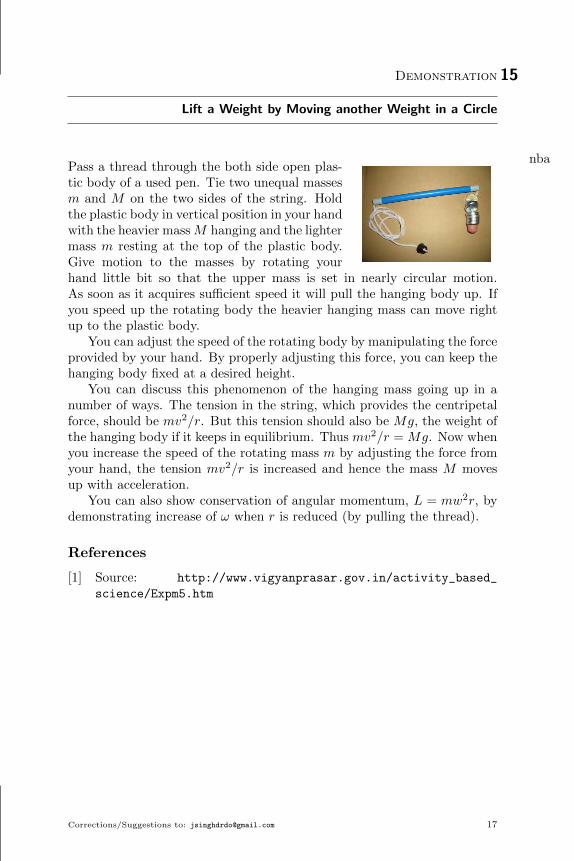
nbaPass a thread through the both side open plas-tic body of a used pen. Tie two unequal massesm and M on the two sides of the string. Holdthe plastic body in vertical position in your handwith the heavier massM hanging and the lightermass m resting at the top of the plastic body.Give motion to the masses by rotating yourhand little bit so that the upper mass is set in nearly circular motion.As soon as it acquires sufficient speed it will pull the hanging body up. Ifyou speed up the rotating body the heavier hanging mass can move rightup to the plastic body.
You can adjust the speed of the rotating body by manipulating the forceprovided by your hand. By properly adjusting this force, you can keep thehanging body fixed at a desired height.
You can discuss this phenomenon of the hanging mass going up in anumber of ways. The tension in the string, which provides the centripetalforce, should be mv2/r. But this tension should also be Mg, the weight ofthe hanging body if it keeps in equilibrium. Thus mv2/r = Mg. Now whenyou increase the speed of the rotating mass m by adjusting the force fromyour hand, the tension mv2/r is increased and hence the mass M movesup with acceleration.
You can also show conservation of angular momentum, L = mw2r, bydemonstrating increase of ω when r is reduced (by pulling the thread).
References
[1] Source: http://www.vigyanprasar.gov.in/activity_based_
science/Expm5.htm
Corrections/Suggestions to: [email protected] 17

Demonstration 16
Key-bottle experiment
ifaIntroduction: This is an eye catching demonstration which gives an insightinto many concepts of physics like friction, connected motion, vertical circle
What do you need: 200 ml plastic bottle filled with water, key, 1msturdy thread, a used pen
What to do:
1. Tie the plastic bottle to one end of the thread and tie a small key tothe other end of the thread.
2. Pass the thread over the body of the pen which acts as a pulley.
3. Now hold the pen in one hand and the key tied to the thread in yourother hand such that it makes an angle of around 45 degree with thehorizontal.
4. Keep the length of the thread on the side of the bottle hanging overthe pulley much smaller than the length of portion of the thread tiedto the key over the other side of pulley
5. Now release the key.
6. The audience hold their breath as they expect the heavier bottle toslide and crash to the ground
7. But amazingly the bottles downward journey is halted as the threadtied to the key curls many times around the pen and stops any furthermovement.
Why does it happen: When we release the key, the bottle being heavierstarts accelerating down and the key tied to the thread falls down likea pendulum released from its extreme position. But as it falls down thelength of the thread goes on decreasing and its velocity goes on increasing.By the time the key reaches the bottom of the circle it acquires the velocityrequired for completing a vertical circle. So the thread loops around thepen. The bottle still accelerates down so the thread keeps looping aroundthe pen till it stops the motion of the bottle.
As number of loops increase, the friction on the thread increases. Theincrease in the contact area of the thread with the pen increases the normalreaction of the pen on the thread which in turn causes the friction toincrease.
To be merged with Get Going Mug on page 9.
18 Corrections/Suggestions to: [email protected]

Demonstration 17
Spring Potential Energy
gbaTake a toy car with spring mechanism. Makea mark on a uniform floor with a chalk. Windthe key of the car through half a turn, and placethe toy at the mark on the floor. Make anotherchalk mark at the point where the car stops.Measure the distance x between the two marks.This is the distance moved by the car. Rub outthe second mark.
Now, wind the key through a full turn andplace it at the first mark. Measure the distance the car moves beforestopping. Repeat the experiment for one and a half turns of the key andtwo turns of the key. Measure the value of x in each case.
The greater the number of turns, the larger is the distance travelled bythe car. This is because when the spring is compressed more, it stores moreenergy. The distance x is roughly proportional to the energy stored in thespring. Try to get the relation between the energy stored and the numberof turns of the key.
References
[1] Source: H.C. Verma, Foundation Science Physics for Class 9 (3rd ed.),Page 110, Bharati Bhawan, 2006
Corrections/Suggestions to: [email protected] 19

Demonstration 18
Calibrating a Non-Linear Spring
leaObjective: To calibrate a spring and get the mass of a given object.
Apparatus: A spring, A hanger of 100g and 4 separate weights of 100geach, Meter Scale fixed with a nail for hanging the spring , clamp, Objectof unknown mass, Graph paper, 6” plastic scale
Instructions: You have to clamp the given meter scale vertically with thenail /rod on the upper side. It is a nonlinear spring and hence you cannothave a unique spring constant. To measure the mass of the given object youmust first calibrate the spring with the given standard masses, that is toknow the extension of the spring for each of these masses. You should drawa calibration graph with the standard masses and then obtain the mass ofthe given object from the extension corresponding to it. Actual extensionis not needed for this calibration. Do your experiments as accurately onyou can and mentions the possible errors and your efforts to reduce it.
20 Corrections/Suggestions to: [email protected]

Demonstration 19
Linear Momentum of the Ball
dbaTake two identical plastic balls. Make a hole inone of them and fill it with sand. Seal the holewith tape. Now you have two balls of differentmasses. Make a pile of sand on the floor anddrop the lighter ball on it from a height. Theball will penetrate into the send to some depth.Make the pile again and drop the heavier ball onit from the same height. This ball will penetratedeeper into the sand. Dropping from the sameheight ensures that balls strike the sand with thesame velocity. So, increasing the mass increases the depth of penetrationwhen the velocity remains the same.
Now drop one of the balls from different heights on the pile. Droppingfrom a larger height means the ball strikes the pile with larger velocity. So,increasing the velocity increases the depth of penetration when the massremains the same.
If you drop the lighter ball from a greater height and the heavier ballfrom a lower height, it may happen that the depths of penetration becomethe same. This will happen when the product mv is the same.
References
[1] Source: H.C. Verma, Foundation Science Physics for Class 9 (3rd ed.),Page 47, Bharati Bhawan, 2006
Corrections/Suggestions to: [email protected] 21

Demonstration 20
Why Does it Goes Up?
mbaBodies put on an inclined plane come down theplane. This can be understood in terms of po-tential energy. By coming down, the gravita-tional potential energy decreases. A system un-der given conservative forces moves in such away that the potential energy decreases. Thisdemonstration emphasizes this principle in a dramatic way.
Join two plastic funnels at the rim with the help of an adhesive. Thismakes a double-cone. Arrange to make a rail by two spokes in such a waythat the height of the rail as well as the separation between the spokesgradually increases. You can take two pieces of thermocol and push thespokes properly in them to make the structure. The plane of the spokesbecomes an inclined plane. You will have to adjust the geometry by trialfor the demo to work. The height of the rail increases from A to B.
Place a cylindrical object like a pencil near the top of the rail and seethat it comes down as expected. Now place the double cone near the topand it won’t come down. Place it near the bottom. It goes up and settlesnear the top of the rail.
Because of the geometry, as the double cone goes from A to B, suppos-edly up the rail, more and more portion of the middle bulge goes betweenthe spokes and the cone actually dips. You can measure the height of thestraight tube part of the funnel above the table when the double-cone isnear the bottom of the rail and when it is near the top of the rail. It isless in the later case showing that the double cone is actually going downwhile it seems to go up.
Quantification: Ask students to measure change in potential energy intwo cases. Need to give a scale and balance.
References
[1] Source: http://www.vigyanprasar.gov.in/activity_based_
science/Expm4.htm
[2] Arvind Gupta Video: https://www.youtube.com/watch?v=
EXOs38T-HV4
22 Corrections/Suggestions to: [email protected]

Demonstration 21
Counter-intutive Centre of Mass with Bottle
tcaReferences
[1] Arvind Gupta Video: http://youtu.be/
qJQPjFevfws
Corrections/Suggestions to: [email protected] 23

Demonstration 22
Balancing the Scale on Fingers
mdaThis demonstrate the concept of centre of mass.Support a meter stick horizontally with two fin-gers (of two hands). Slide your fingers in andthey will both meet at the center of mass. Toexplain this, you need to understand friction and equilibrium. In staticequilibrium, net force and net torque on the scale is zero.
Give scale to a volunteer. Hold the scale horizontal by placing finger ofone hand below one end of metre scale and finger of another hand belowthe mid point of scale. Ask him to move the finger at the end of the scale.It is easy do so. Now ask him to move the finger at the mid-point. He isunable to do so. Why?
References
[1] Source: https://www.lhup.edu/~dsimanek/scenario/demos.htm
24 Corrections/Suggestions to: [email protected]

Demonstration 23
To find Centre of Mass of a Rectangular Shape
meaObjective: To find the Center of Mass (C.M.) of the given rectangular plate.
Apparatus: Clamp with nail fixed, Plumb Line, 30 cm Plastic Scale, Rect-angular Plate
Instructions: You are given a rectangular cardboard plate and are supposedto find out its Center of Mass. You can think of your method with the givenapparatus, but one way is to hang the board from the fixed nail and with thehelp of the plumb line you can locate vertical lines through the holes. If youdecide for that, mark two or three points on the surface, along the plumbline for each hole. Dont draw lines till you finish with all the holes.Only atthe end, put the plate on the table and draw all the lines using scale andpencil. Write your name and roll number on the sheet before submittingto the evaluators.
Corrections/Suggestions to: [email protected] 25

Demonstration 24
To Find the Coefficient of Restitution
reaObjective: To find the coefficient of restitution in an inelastic collision.Apparatus: An wooden block with a trench, a sun mica board, a caromstriker, powder, scale, pencil, eraser.Introduction: When an object hits a wall obliquely, it reflects. If frictionduring the collision can be neglected, the parallel component of velocityremains unchanged but perpendicular component changes. If the collisionis elastic, the net speed remains the same and hence the perpendicularcomponent also remains the same. As a result, angle of incidence is equalto angle of reflection. However, if the collision is partially inelastic theperpendicular component decreases and the angle of reflection will exceedangle of incidence. The coefficient of restitution is obtained by e = tan θ1
tan θ2,
where θ1 and θ2 are the angles of incidence and reflection. In the experimentyou will use this equation.Experiment: Look at the wooden block and the sunmica board. The boardcan be fitted to the block just by inserting it in the trench. You can keepthe whole thing on a horizontal surface, the board making an inclined planeof a small angle. This inclination has no role in the experiment.
Half the wall of the block is wood and the other half is foam. By justflipping the block you get the other kind of wall on the top. Sprinkle somepowder on the board very gently, so that a thin layer is formed. Put strikeron the board at some distance from the wall and flick it so as to hit thewall obliquely. The angle should be large enough to give you significantdifference between the angles of incidence and reflection if any. As thestriker moves through the powder, it makes a trail which you can see. Verycarefully draw pencil lines to mark the incident and reflected directions ofthe center of the striker. Draw perpendicular to the wall that goes throughthe point of intersection of these two directions.
Now you can get e from the equation. Repeat at least 3 times withwooden surface and 3 times with foam surface.Hazards: No hazardsAcknowledgement: Designed by Shiksha Sopan.
26 Corrections/Suggestions to: [email protected]

Demonstration 25
It is not Easy to Do Simple Movements!
ndaSit on chair with legs and backbone vertical. Tryto stand up without moving the upper portion ofyour body forward or lower portion of your bodybackward. Can be used to explain concepts likecentre of mass, torque etc.
Variant: Turn your right side to the wall.Turn your right foot and cheek against the wall.Now try to lift your left foot off the floor.
Both of these stunts require you to shift yourcenter of gravity away from the support base.The body maintains balance with little adjust-ments so automatic that we never think about them.
References
[1] Source: http://www.arvindguptatoys.com/arvindgupta/
betyoucant.pdf
Corrections/Suggestions to: [email protected] 27

Demonstration 26
Win a 100 Rs Note
odaStand with your heels against a wall and yourfeet together. Place a 100 Rs note on the floorabout a foot in front of your feet. Now, try topick up the 100 Rs note without moving yourfeet or bending your knees. You cant pick it up.This demo explains concept like centre of mass,static equilibrium, torque etc.
When you stand straight against the wall, your center of gravity is overyour feet (base) as it should be. When you bend forward, you move yourcenter of gravity forward. In order to keep your balance, you must moveyour feet forward too. This maintains the base under the center of gravityneeded for stability. If you persist in trying to pick it up, you’ll fall flat onyour face!
References
[1] Source: http://www.arvindguptatoys.com/arvindgupta/
betyoucant.pdf
28 Corrections/Suggestions to: [email protected]

Demonstration 27
Self Balancing Toy
pdaThis toy is in the form of question mark. It balances itself.
Corrections/Suggestions to: [email protected] 29

Demonstration 28
Rolling and Kinetic Friction
qdaKeep a pen (cylinder) between your palms.When you move the palms, observe the trans-lation motion of the pen and your hand. Thisdemo can be used to show rolling without slip-ping, translation and rotational motion etc.
30 Corrections/Suggestions to: [email protected]

Demonstration 29
Gyroscope from cycle wheel
heaIntroduction: It is a common experience thata bicycle can be parked only when we supportit with a stand otherwise it will fall down. Butthe same bicycle when moving on the road canbe balanced very well on its two wheels. Wheelsof a moving bicycle have a very large spin angu-lar momentum which helps in maintaining thebalance of the bicycle. This is the basic prin-ciple of a gyroscope. In this demonstration wewill see how a spinning cycle wheel is affectedby external torque.
Equipments:A cycle wheel with an axle, rope
Procedure
1. Attach a rope to the axle of the cycle wheel.2. Hold the cycle wheel by the rope. See that the wheel topples down.3. Hold the cycle wheel from its axle and give it a spin in clockwise
direction.4. When the wheel acquires a large angular velocity, leave the axle and
hold the wheel by the rope attached to the axle.5. See that the wheel instead of toppling this time starts prcising around
the rope in the anticlockwise direction when seen from above.6. Now hold the cycle wheel from the axle, spin it in anticlockwise di-
rection, and again hold it with the rope but this time see that thewheel prciss in a clockwise direction around the rope.
7. When the wheel is held by the rope, (i) why does it topple when it isnot spinning and (ii) why does it start prcising when it is spinning?
Discussion: When we hold the cycle wheel by the rope attached to theaxle, the tension in the rope and the weight of cycle wheel acting throughthe centre of mass of the wheel cause a torque which topples the wheel. Aspinning wheel has a spin angular momentum L, whose direction is givenby the right hand thumb rule. If you spin it in clockwise direction, the spinangular momentum L is away from you and perpendicular to the plane ofthe wheel. If you spin it in anticlockwise direction, L is towards you. Ifthe angular velocity is large, L is also very large.
Now, when a torque is applied by holding the rope, the torque acts in adirection perpendicular to L. This causes an additional very small angularmomentum dL in the direction of the torque. The net angular momentumis now the vector sum of L and dL which is no more perpendicular to theplane of the wheel but is slightly tilted towards the applied torque. This
Corrections/Suggestions to: [email protected] 31

32 Demonstration 29. Gyroscope from cycle wheel
causes the angular momentum L to follow the torque and the wheel startsprcessing about the rope.
Reversing the direction of angular momentum L causes the wheel toprcess in an opposite sense.
Variant: This demo can be done with Toy Gyroscope on page 35.

Demonstration 30
To study the theorem of perpendicular axes in Moment of Inertia
xeaObjective:To study the theorem of perpendicular axes in Moment of Inertia.Introduction: For planer bodies, the sum of the moments of inertia abouttwo axes, perpendicular to each other but in the plane of the body, equalsthe moment of inertia of the body about the axis through the same pointperpendicular to the plane. The moment of inertia of an object can befound by suspending it from a support and allowing it to oscillate aboutthe suspension. The time period happens to be proportional to the squareroot of the moment of inertia. T = k
√I.
Apparatus: An wooden plate with two bolts fixed on the sides and one atthe center, a wire fixed with a nut, clamp-stand, stop watchInformation for the students: Suspend the plate by fixing the bolt in a nuton a side. Let the plate be suspended . Now twist the plate about thevertical axis and measure time period using stop watch. Make sufficientno. of readings to be sure of the value. This gives moment of inertia Ix upto the proportionality constant.
Open the nut and screw it in the bolt on other side. Get the timeperiod of twist oscillations. From this find the moment of inertia Iy up tothe proportionality constant.
Again open the nut and screw it in the bolt at the center of the plate.Get the time period of twist oscillations. From this find the moment ofinertia Iz up to the proportionality constant.
Find the value ofIx+IyIz
.Acknowledgement: Developed at SGM-IAPT Anveshika
Corrections/Suggestions to: [email protected] 33

Demonstration 31
Paper Helicopter
ccaThe paper helicopter is very easy to make. Cutout a rectangular piece of paper approximately4 cm× 15 cm. Fold the paper (along length) inequal halves and then unfold it. Cut along thefold crease upto half of the length. Now, cutabout 1/3 through the paper laterally a littlebelow your first cut on both sides and fold these parts along length. Makefolds as shown in paper. Don’t forget to add a paper clip at the bottom.The helicopter rotates when you drop it from a height of 2 m or above. Whythe blades rotates? If you fold the blades in opposite direction then direc-tion of rotation changes! This simple toy can be used to explain conceptof centre of pressure, torque, angular momentum etc.
References
[1] Web Source: http://www.wikihow.com/
Create-a-Paper-Helicopter
34 Corrections/Suggestions to: [email protected]

Demonstration 32
Gyroscope Using Toy Motor
dcaThe equipment consists of a toy motor poweredby two AA batteries.Making: Take a toy motor. Take two CD andan alminium sheet of the size of CD. Place thealuminium sheet between two CD. Fix this as-sembly to the axle of motor. Paste/draw Net-won’s disc on outer CD. This equipment can beused for three concepts as discussed below.Newton Disc: When connected to battery, the motor start rotating andyou get a low cost Newton’s disc.Magnetic Brake: Bring a magnet close to the disc. The speed reduces. Youcan explain about eddy currents and magnetic brake. See also page 164.Gyroscope: Suspend entire assembly was from a thread which does notpass through centre of mass. When motor is switched on, the CD rotatesproviding angular momentum to the system. The torque due to weightabout centre of mass causes angular momentum (direction) to change andthe system precesses about vertical axis. Changing the polarity on battery
change direction of rotation. Physical law is ~τ = d~Ldt . This set up seems to
be good for classroom demo as carrying bicycle wheel in classroom is littlebit cumbersome. See also page 31.
Corrections/Suggestions to: [email protected] 35

Demonstration 33
Coupled Pendulum
kcaCoupled Pendulum to show energy transfer.Similar to what Masti Ji shown in KolkataSRP.
36 Corrections/Suggestions to: [email protected]

Demonstration 34
SHM Phase and Phase Difference
feaIntroduction: An oscillating pendulum, a corkbobbing up and down in water or the periodicmotion of the mass attached to a spring have onething in common. They are all executing sim-ple harmonic motion (SHM). Simple harmonicmotion is a special type of oscillation. The con-cept of phase and phase difference associatedwith SHM is generally difficult to comprehend.In this demonstration this concept of phase andphase difference can be understood easily.Equipments:A stand, two pendulums made by attaching two similar plas-tic balls with two threadsProcedure:
1. Hang the two threads attached to the plastic balls to the stand tomake the two pendulums.
2. Make the length of the threads same.3. Take both the balls to one extreme and release them together.4. Both the balls oscillate in a similar manner i.e. they have same time
period, reach the other extreme in the same time and are at sameposition at any instant of time.
5. We say that both are in the same phase and their phase difference iszero.
6. Now take one ball to one extreme and the other ball to the otherextreme and release them simultaneously.
7. See that the balls move opposite to one another at all times i.e. if onemoves right the other moves left. Also if one is at the right extreme,the other is at the left extreme.
8. We say that both are in opposite phase and their phase difference isπ.
9. Now make the length of one of the pendulums slightly less than theother
10. Again release both of them simultaneously from the extreme position.11. This time the two do not move together, one with the smaller length
reaches the other extreme earlier, so we say that they are not in phase.12. But the phase difference between them does not remain constant,
first it increases with time and becomes equal to , then the phasedifference starts decreasing and becomes equal to zero and again itincreases to and then goes to zero. This process repeats itself and iscalled beats.
Discussion: SHM is an oscillation in which a particle moving in a straight
Corrections/Suggestions to: [email protected] 37
38 Demonstration 34. SHM Phase and Phase Difference
line experiences a force which directs it towards its mean position and themagnitude of the force is proportional to the displacement from the meanposition. It can be represented by a sine or cosine function. The argumentof the sine or cosine function is called the phase of the particle executingSHM. Phase tells about the state of the particle at any instant.
In the above case the SHM of the pendulums which are released fromtheir extreme position can be represented by the equationsX1 = A1 cos(ω1t+θ) and X2 = A2 cos(ω2t+ φ), where A1 and A2 are the amplitudes, θ andφ are the initial phases, ω1 and ω2 are the angular frequencies and thearguments (ω1t+ θ), (ω2t+φ) are the phases of the two pendulums at anyinstant.
Since the frequency of the pendulum is dependent on its length, whenthe length of the threads is kept same ω1 = ω2. Now if the balls are releasedtogether from
1. Same extreme, initial phases θ = φ = 0 and phase difference = 02. Opposite extremes, θ = 0 and φ = π and phase difference = φ−θ = π.
Also the amplitudes A1 = A2.
When the length of the threads is different ω1 6= ω2. Now if the ballsare released together initial phases θ = φ = 0 but the phase difference is(ω1t−ω2t) which changes with time and oscillates between the value 0 andπ causing beats.

Demonstration 35
Resonance in pendulum by hand
geaIntroduction: Some times in a movie we seethat when an opera singer sings, the glass inher hand shatters. Also at times when we closethe door, the window panes in the room startrattling. The phenomenon governing the aboveevents is resonance. When the frequency of theopera singer (or closing door) matches with thefrequency of the glass (or window), resonance occurs. In this demonstrationwe show this phenomenon of resonance.Equipments:A pencil, a thread, a nutProcedure:
1. Tie a nut to one end of a thread.2. Wrap the other end of the thread on a pencil to make a simple pen-
dulum.3. Apply a small force on the pendulum to make it oscillate.4. Leave it free so that it starts oscillating with its natural frequency.5. Now rotate the pencil in clockwise and anticlockwise direction peri-
odically with your fingers.6. Do it very slowly(at frequency much less than natural frequency of
pendulum).7. See that the amplitude of the oscillations becomes very less.8. Again give a rotation to the pencil in a similar manner, but this time
do it very fast.(at frequency much more than the natural frequencyof pendulum)
9. The amplitude of oscillation is still very less.10. Now rotate the pencil in such a manner that frequency of the peri-
odic rotation given to the pencil matches with the frequency of thependulum. This will require some practice.
11. See that the amplitude of oscillation of the pendulum becomes verylarge.
Discussion: Every body oscillates with its natural frequency when it isleft free.This natural frequency depends on the shape, size and materialof the body. If the body is subjected to a periodic force the body startsoscillating with the frequency of this periodic force after some time. Butthe amplitude of these oscillations is very small if the forced frequency isdifferent from the natural frequency. If the forced frequency happens tomatch with the natural frequency, the body gains a lot of energy and itsamplitude become very large. We call this the resonant frequency.
Corrections/Suggestions to: [email protected] 39

Demonstration 36
To Study Torsional Oscillation of a Rectangular Body
oeaObjective:To study the torsional oscillation of a rectangular body suspendedby two non parallel threads.
Apparatus: Clamp, Suspension plate with nails fixed, Oscillating plate withhooks and threads fixed, Meter Scale, Stop Watch, Graph Paper
Instructions: Suspend the oscillating plate using the threads and the innerpair of nails on the suspension plate. The upper edges of the plate shouldbe horizontal.
Rotate the plate about the vertical bisector through a small angle andrelease. The plate should start oscillating.
Let the height of the nails over the upper edge of the plate be H andtime period of oscillation be T . You are suppose to find the relation betweenT and H. So measure T and H at appropriate length and draw a graphbetween T and H. From this, guess whether T ∝ H2, T ∝ H or T ∝√H.
40 Corrections/Suggestions to: [email protected]

Demonstration 37
Why Balloons come Closer?
acaThe Bernoulli principle enables aircraft to fly.This experiment demonstrate Bernoulli’s prin-ciple in a simple way. Hang two balloons a fewinches apart. Blow air between them. Whathappens? Whether balloons come closer or goesfarther away? Why? You can also do this ex-periment by blowing air above a strip of paper.
Electrostatic Variant: Same setup can be used to show electrostaticattraction and repulsion between balloons when they are charged.
Corrections/Suggestions to: [email protected] 41

Demonstration 38
Why the fluid does not comes out?
kdaUse the scissors to make a small hole on the sideof the water bottle, closer to the bottom.
The water starts coming out in a parabolicpath.
Fill the water bottle and put your finger overthe hole. Take your finger off the hole and letthe water bottle drop. What happened duringthe drop? Did the bottle leak?
When the cup is at rest, the force of gravitypulls downward upon the water. At the locationof the holes, there is nothing to balance gravity’s force and prevent waterfrom spilling out of the cup.
However, when the cup is in free fall, the water will not leak, making itseem as though the water is not experiencing the downward pull of gravity.It is merely falling to the ground at the same rate as its surroundings (thecup).
References
[1] Source: http://www.physicscentral.com/experiment/
physicsathome/free-fall.cfm
42 Corrections/Suggestions to: [email protected]

Demonstration 39
Suspending a Cup by a Balloon
rdaThis demo explains the concept of air pressureand Boyle’s law, PV = constant.
Blow up a balloon to less than half its poten-tial size and close off the opening. Then placethe mouth of a paper cup against the side of the balloon and hold it therewhile you blow up the balloon the rest of the way. You will find the cupbecomes “fastened” to the surface of the balloon and will actually hold onfairly tightly until you force the cup to “let loose” of the balloon. Becauseof the curvature of the surface of the balloon, when it is not blown up allthe way, you place the mouth of the cup against its surface, and the balloonextends a small distance into the cup. Then, as you blow up the balloonfarther, its curvature becomes such that the volume of the air trappedinside the cup becomes larger, thus lowering the pressure inside the cup.The pressure inside the cup is now less than atmospheric pressure, and theatmosphere outside the cup “pushes the cup” onto the balloon.
References
[1] Source: https://www.physics.umn.edu/outreach/pforce/circus/airpressure.html
Corrections/Suggestions to: [email protected] 43

Demonstration 40
Keep the Paper Dry in Water
sdaStuff a large handkerchief or some crumpled-newspaper into an empty glass or jar. Makesurethe handkerchief wont fall out when youturn theglass upside down.Then, fill a pot withwater. Holding the glass sothat its mouth isdown, put the glass deep into thepot of waterand hold it there. After a minute ortwo, pull the glass out of the water andremove thehandkerchief.
Water cannot fill the glass because the glass is already filled with air.The “empty” glass is full of air. So, air takes up space. Air is a gas. It hasno size or shape of its own butwill fill every space it can.
References
[1] Source: arvindguptatoys.com http://goo.gl/pqaj2C
44 Corrections/Suggestions to: [email protected]

Demonstration 41
Push Water in a pair of Connected Syringes
tdaThis simple experiment is often taken as an ex-ample of Pascal’s law of transmission of Pressureor a demonstration of F = PA. However thispopular belief does not pass the test of deeperanalysis. Equipments needed are two syringesof different sizes connected by a small flexibleplastic tube. Some water is filled in one of thesyringes. The procedure is,
1. Suppose you have water in the bigger syringe and the piston of thesmaller syringe is staying against the end. Hold the bigger syringebetween the two fingers and a thumb. The thumb is on the circularbase of the piston while the fingers are on the two extrusions of thebarrel.
2. Push on the base by the thumb so that water goes from the biggersyringe to smaller one. Feel the amount of force.
3. Now water is in the smaller syringe. Holding the this syringe as usualbetween two fingers and one thumb, push the water back to biggersyringe. Feel the force you have to apply.
4. Compare, in which case you had a apply a larger force.
As you are comparing forces in two different experiments (Step 2 and 3above), you should not use Pascal’s law which talks about increase in pres-sure everywhere in the liquid, but at the same instant. For the same reasonyou cannot equate pressure in two cases and make force proportional to thearea of the base. Then what is it?
References
[1] Source: Utsahi Physics Teachers Website http://goo.gl/4uFmTu
Corrections/Suggestions to: [email protected] 45

Demonstration 42
Blow Air in a Long Air Bag
udaHere’s the challenge. How many breaths wouldit take to blow up a 2 meter (8 ft) long bag? De-pending on the size of the person, it may takeanywhere from 10 to 50 breaths of air. However,with a little practice and some scientific knowl-edge of air... you will be able to inflate the bagusing only one breath!
46 Corrections/Suggestions to: [email protected]

Demonstration 43
To find the atmospheric pressure using a syringe and weights
seaObjective:To find the atmospheric pressure using a syringe and weights.Apparatus: A syringe with one end closed and very little air trapped in it.An identical extra syringe, Support system for keeping the syringe fixedin vertical position. A pan suspended from the lower end of the syringebarrel, known weights.Introduction: Suppose there is no air trapped in the syringe. When youput small amount of weight on the pan, the piston stays in its position.If you pull the piston down and release, it will be pushed up because theforce by the atmosphere is more than the weight put. But if the weight isequal to the force by the atmosphere, and you pull the piston little bit andrelease, the piston will stay wherever it is released. By measuring the innerarea of cross section of the syringe, you can get the atmospheric pressureby Atmospheric Pressure = Weight/Area.Experiment: Find the inner cross sectional area of the syringe. The weightrequired is definitely more than 1/2 kg.wt. So put 1/2 kg weight on thepan. Because of little air trapped the piston might come down little bit.From here pull the barrel little bit and release. If it goes up, you need toput more weight. Use smaller weights to find the position where the pistonstays wherever it is left. Try to get this situation correctly.
You might find that even if you make small variation in weight the pistonbehaves similarly and stays wherever it is left. This is due to friction. Findthe range of weights for which this situation occurs. Use the mean weightand calculate the atmospheric pressure.Questions: Due to the trapped air in the syringe do you expect the mea-sured atmospheric pressure to be more or less than the actual value? Canyou estimate this error in percentage.
Repeat at least 3 times to check for consistency.Hazards: Be careful to handle weights, they should not fall on your feet.Acknowledgement: Designed by Shiksha Sopan
Corrections/Suggestions to: [email protected] 47

Demonstration 44
To measure the viscosity of water
veaObjective: To measure the viscosity of water.Introduction: Viscosity is counterpart of friction in liquids. When one layerof a liquid attempts to slip over the adjacent layer, there are forces by thelayers on each other to oppose the relative possible velocity. Essentially itopposes the velocity gradient in a liquid (or a gas). The effect is measuredby “Coefficient of Viscosity”. One standard way to get the viscosity ofwater is to let it flow through a narrow tube, and use Poiseuille equationdVdt = ∆Pπr4
8ηL , where dVdt is the volume of water coming out of the tube, ∆P
is the pressure difference across the tube, r is the radius of the tube, L isthe length of the tube and η is the coefficient of viscosity.Apparatus: A bottle with a plastic tube fixed at bottom, a syringe barrelclosed at its tip, a stop watch, a screw gauge, scale.Information for the students: The tube fixed in the bottle is the plasticsleeve over electric wires. We are giving you the wire removed from thesleeve. Assume that the inner diameter of the tube is equal to the diameterof the wire. Measure the diameter of the wire to get the radius of the tuber.
Measure the length L of the tube using a plastic scale. We have put amark near the neck of the bottle. Measure the height of this mark abovethe tube. You will be putting water in the bottle up to this height andthen ∆P will be equal to hρg.
Close the tube with one hand and pour water in the bottle up to themark. Release the tube. Water will start coming out from the tube. Startcollecting the water in the syringe and at the same time start the stopwatch. Collect water up to say 3/4 of the syringe and stop the stop watch.Note down the time and the volume of water collected. This gives dV
dt .Now you can put everything in Poiseuille equation to get the coefficient ofviscosity η. Repeat at least 4-5 times to get the average and variation inη
48 Corrections/Suggestions to: [email protected]

Demonstration 45
Archimedes Principle
fbaFill a 1-litre plastic bottle with water and screwon its cap. Hold the bottle by the cap. You willfeel some strain in your fingers because you haveto apply an upward force to hold the bottle atrest.
Now dip the bottle in a bucket of water,putting about half the bottle inside water. Thestrain on your fingers will now be less. This means that you are applyinga lesser upward force to hold the bottle at rest. This is because the waterexerts an upward force on the bottle.
Gradually immerse more of the bottle inside the water. As you do so,the strain on your fingers reduces further. This means that the upwardforce exerted by the water increases as more of the bottle gets into thewater. So, when the bottle is completely immersed in water, you have toapply a very small force to hold the bottle.
Take a thick, long rubber band and cut it so that you have two free ends.Tie a stone at one end, and tie the other end to a fix support. The rubberband will get stretched. Because of this it will pull the stone upwards. Thispull balances the weight of the stone.
Now, what do you think will happen if you immerse the hanging stonein water? To check whether your answer is correct, put a jug of waterbelow the stone so that the stone gets immersed in water. You will findthat the rubber band is now stretched by a smaller amount. Why?
References
[1] Source: H.C. Verma, Foundation Science Physics for Class 9 (3rd ed.),Page 58, Bharati Bhawan, 2006
Corrections/Suggestions to: [email protected] 49

Demonstration 46
Effect of Soap on Surface Tension
lcaTake a bowl of water. Spray talcum powder on it. The powder is uniformlydistributed. Why? Now, slowly drop a drop of soap solution in it. Whathappens? Shown by Patil Ji in Kolkata SRP.
50 Corrections/Suggestions to: [email protected]

Demonstration 47
Rise of Paper (Welcome) due to surface tension
mcaTake Newspaper. Fold/cut it in such a way that welcome is written on it.Take a tub/bucket of water. Slowly Welcom rises. Describe by Amit Janain Kolkata SRP.
Corrections/Suggestions to: [email protected] 51

Demonstration 48
Pressure in Two Balloons connected by transparent pipe
rcaNWUPT14. NEST 2014.
References
[1] http://youtu.be/RCiHE3JO6aQ?list=
PLjVcSEe2pNnZiJpmGp9-iGmjkJzf4QGrX
52 Corrections/Suggestions to: [email protected]

Demonstration 49
The Fun of Three Bottles
bdaPressure of atmosphere is all pervading in oursurrounding. Also it shows up in various ways.Liquid columns have their own pressure. Whileatmospheric pressure is almost uniform overheights of tens of meters, liquid pressure variessignificantly with depth of the column. We aregiving a fun-filled way to understand and prac-tice these phenomena.
Suppose you have water in the bigger syringe while, the piston of thesmaller syringe is staying against the end. Hold the bigger syringe betweenthe two fingers and a thumb. The thumb is on the circular base of thepiston while the fingers are on the two extrusions of the barrel. Pushon the base by the thumb so that water goes from the bigger syringe tosmaller one. Feel the amount of force you have to exert. Now water is inthe smaller syringe. Holding the this syringe as usual between two fingersand one thumb, push the water back to bigger syringe. Feel the force youhave to apply.
Three bottles give enough room for discussion of air and water pressure.Flow direction in a tube is decided by the pressure difference at the twoends. Calculation of pressure at end of the tube involves air expansion orcontraction if the cap is closed and any water column above that end.
References
[1] Source: UPT: http://goo.gl/GEPvxk
Corrections/Suggestions to: [email protected] 53

Demonstration 50
Rising of water due to centrifugal force!
cdaJoga Chandrasekhar!
54 Corrections/Suggestions to: [email protected]

Demonstration 51
To study the extension-load characteristics of bicycle valve tube
weaObjective:To study the extension-load characteristics of bicycle valve tube.Introduction: For a linear spring described in textbooks, the extensionis proportional to the applied force. But most materials are linear for asmall extension range only. In this experiment you will study the relationbetween the load applied on a hanging bicycle valve tube and its extension.Also rubber shows hysteresis so the extension depends not only on the forcebut also on the history of stretching.Apparatus: bicycle valve tube with knots at the ends, a stand to suspendthe tube, a hanger weight, weights, meter scale vertically fixed, graph paperetc.Information for the students: Measure the natural length of the tube. Sus-pend the tube in the stand and the hanger weight from its lower end. Putthe weights one by one and note the reading of appropriate point on thescale. Each time write the load and the scale reading in a table. Calculatethe extension. Once you have gone up to say 1 kg, remove the weights oneby one and each time note the extension. Write in the same table. Makesure you monotonically increase the load and the monotonically decreasethe load. Also you have to give sufficient time after putting or removingthe load for the tube to settle down.
Draw a graph with load on the x-axis and extension on the other. Thearea under the curve gives the work done by the load, Calculate the workdone in the increasing load cycle and also on the decreasing load cycle.Your answer should be in joules. Is any of the two positive? Is any of thetwo negative? What is the total energy dissipated in the whole process?Acknowledgement: Developed at SGM-IAPT Anveshika
Corrections/Suggestions to: [email protected] 55

Demonstration 52
To study torsional oscillations of a wire
bfa
56 Corrections/Suggestions to: [email protected]

Part II
Waves
57


Demonstration 53
Vibrations, Rerefaction and Compression in a Long Spring!
ada
Corrections/Suggestions to: [email protected] 59

Demonstration 54
Visualize Wave Motion
ydaThe live model is made up of straws and beads.This model is used to explain concept of wavemotion, reflection of wave from denser medium,wavelength etc. The movement of disturbace(wave) can be easily seen. Also, it shows howspeed of sound increases with increase in ten-sion.
References
[1] Arvind Gupta Youtube Video http://youtu.be/IlF8sdHTqaU
60 Corrections/Suggestions to: [email protected]

Demonstration 55
Compression and Rarefaction in Longitudinal Waves
zdaThis experiment uses a slinky to show compres-sion and rarefaction in a longitudinal wave.
References
[1] Arvind Gupta Youtube Video http://www.
tarangscientificinstruments.com/manuals/Slinky-Spring.pdf
Corrections/Suggestions to: [email protected] 61

Demonstration 56
Sound is Produced by Vibrations
hbaUse tape to fix a string to a small plastic ball.Suspend the ball from a support. Now, strike aprong of a tuning fork against a pad, and touchthe ball with the prong. The ball will move awaywith a jerk. This shows that the prongs arevibrating. When they vibrate, they move backand forth. So, when a vibrating prong touchesthe ball, the ball moves.
Gently touch the surface of the water kept invessel with a prong of a tuning fork, after strik-ing it against a pad. Since the prong vibrates,it creates ripple in water.
References
[1] Source: H.C. Verma, Foundation Science Physics for Class 9 (3rd ed.),Page 111, Bharati Bhawan, 2006
62 Corrections/Suggestions to: [email protected]

Demonstration 57
Reflection of Sound
ibaTake two long, identical tubes and place themon a table near a wall. Ask your friend to speaksoftly into one tube while you use the othertube to listen. You will find that you hear yourfriend’s voice best when the tubes make equalangles with the wall, i.e., when 6 i = 6 r. Also,if you lift your tube off the table, you will not be able to hear your friend’svoice clearly. This is because your tube, the incident sound and the normalare no longer in the same plane.
Repeat the experiment by placing flat objects of different materials(steel and plastic trays, a cardboard, a tray draped with cloth, etc.) againstthe wall. You will find that hard surfaces reflect sound better than softones.
References
[1] Source: H.C. Verma, Foundation Science Physics for Class 9 (3rd ed.),Page 121, Bharati Bhawan, 2006
Corrections/Suggestions to: [email protected] 63

Demonstration 58
Visualize your Sound!
ncaThis was shown in NWUPT14. Take a pipe of approx 4 inch dia and6 inch length. Tie a rubber sheet (balloon) on one side. Fix a small planemirror/reflector on the sheet. Incident a laser on reflector and producesound of different letter from other side of the pipe. The light is reflectedand produce different pattern for different letters.
64 Corrections/Suggestions to: [email protected]

Demonstration 59
The Phenomenon of Beats!
ycaDemonstrate phenomenon of beat using a light source fitted on hacksawblade. Saw first time at SGM Kanpur.
Corrections/Suggestions to: [email protected] 65

Demonstration 60
The Optics of Waves on Water Surface
icaThis experiment is based on HC Verma video https://www.facebook.
com/photo.php?v=449997568411615&set=vb.100002041261681&type=3&theater
References
[1] HC Verma Video: https://www.facebook.com/photo.php?v=
454642061280499&set=vb.100002041261681&type=3&theater
66 Corrections/Suggestions to: [email protected]

Demonstration 61
Interference with thread!
scaA model to show variation of phase differencebetween two waves interfering in two slits exper-iment. Use thread and sleeve (equally spaced)for demo. Shown in NWUPT 14
Corrections/Suggestions to: [email protected] 67

Demonstration 62
Diffraction of light from a thin wire!
hdaJCR! This demo shows diffraction pattern pro-duced by a thin wire.
References
[1] Source: http://www.optics.rochester.
edu/workgroups/berger/EDay/
EDay2008_Diffraction.pdf
68 Corrections/Suggestions to: [email protected]

Demonstration 63
Interference in Ripple Tank!
gdaJCR!
Corrections/Suggestions to: [email protected] 69


Part III
Optics
71


Demonstration 64
Multiple Images with Plane Mirrors
ubaTake two plane mirrors (without frame). Placeboth the mirrors side by side and fix the junctionwhere they meet with a cello tape. Now youwill be able to open and close the mirrors like abook. Place both the mirrors at a small angleapart in the upright position on the floor. Placea lighted candle in the space between the two mirrors. You will observemany images of the candle which makes a very beautiful scene. Now bygradually decreasing the angle between the mirrors observe the imagesbeing formed. You will now observe more and more images of the candlebeing formed. Similarly, if the angle between the mirrors is increased thenumber of images decreases and when this angle is 180, only one imagewill be visible.
When the angle between the two mirrors is 180 they together act likea single mirror so that only one image is visible. As the angle between themirrors gradually decreased, not only the candle but the mirrors themselvesget imaged in one another. That is why when the angle between the mirrorsis decreased one observe image within image, and image within that image,and so on. In this way one observes a lot many images. If the angle betweenthe mirrors is finally decreased to zero, infinite images are expected to beformed. The situation is similar to the hair dresser saloon where we seemultitude of images.
Fill a transparent glass tray with water and fix two similar mirrors atits opposite ends. See the image being formed. What you see is a very longwater canal. Think how this happens?
References
[1] Source: http://www.vigyanprasar.gov.in/activity_based_
science/Exp15.htm
Corrections/Suggestions to: [email protected] 73

Demonstration 65
Scattering of Lights of Different Colours
oaaTake water in a transparent container which isat least 18− 20 cm long (or wide). Add two orthree drops of milk to the water and shine apowerful torch through the water. Look froma side of the container. You will see that thecolour of the milk-water mixture changes withdistance from the torch. Near the torch, the colour is milky blue. And atthe other end, the colour is orange or red. If you add a few more drops ofthe milk, the colours become darker. Look at the face of the torch throughthe liquid. It will look reddish.
74 Corrections/Suggestions to: [email protected]

Demonstration 66
Scattering of Light
naaPlace a glass of tap water in front of a paperscreen or wall. Shine a laser pointer (or a pow-erful torch) through the water. You will only seespots of light on the screen and on the wall ofthe glass. Now, put a drop of milk in the waterand shine light through the water. You will beable to see the path of the light through the water.
References
[1] Related Video NEST 2014: http://youtu.be/nMFrIjpMxu4?list=
PLjVcSEe2pNnZiJpmGp9-iGmjkJzf4QGrX
Corrections/Suggestions to: [email protected] 75

Demonstration 67
Dispersion of Light by a Prism
maaMake a narrow slit on a stiff piece of paperand make it stand vertically. Allow sunlight ortorchlight to fall on the slit, to create a narrowbeam of light. Let this beam fall on a rectan-gular face of a prism placed near a wall. Lightwill pass through the prism and fall on the wall.Rotate the prism till you see a band of colourson the wall.
76 Corrections/Suggestions to: [email protected]

Demonstration 68
Tracing the Ray of Light through a Prism?
laa
A
C
B
Q
P
R
S
D
T
KL M
N
i1 r1 i2r2
δ
Let us trace a ray of light through aprism. Fix a sheet of white paper ona board. Place the prism on it anddraw its outline ABC. Draw a linePQ that meets AC at Q, at an angleof about 30 to AC. Fix two pins Kand L vertically on this line, about10 cm apart. Now look at the imageof the pins from the side BC of the prism. Fix a pin M such that it appearsto be in a straight line, the other pins will disappear behind M. Fix anotherpin N (at least 10 cm from M ) such that all four pins appear to be in astraight line.
Remove the prism and the pins. Join by a straight line the points wherethe pins M and N were inserted. This line, SR, meet BC at R. Join Q andR by a straight line. The lines PQ, QR and RS represent the directions ofthe incident ray, the ray within prism and the emergent ray respectively.
Draw perpendiculars to AC and BC at Q and R respectively. Measurethe angles i1, r1, i2 and r2. Also, measure the angle of deviation, i.e., theangle between PQ and RS.
Corrections/Suggestions to: [email protected] 77

Demonstration 69
Advantage of having Two Eyes?
kaaKeep a glass of water on a table. Ask yourfriends to sit about 5− 6 m from the table. Holda coin in your hand and move it slowly nearthe glass. One by one your friends should coverone eye and say when the coin is just above theglass. When they say so, drop the coin. Youwill find that in most cases your friends judgethe position of the coin wrongly, and the coinfalls outside the glass. But if they look throughboth the eyes, they will be able to judge the po-sition of the coin correctly most of the time, andthe coin will drop into the glass. This happensbecause we are unable to judge depth, or therelative distance between objects, with one eye, especially when the ob-jects are at some distance from the eye. Two eyes are required to perceivedepth. Also, we can see a wider area with two eyes than with one eye.
References
[1] Source: H.C. Verma, Foundation Science Physics for Class 10,Page 37, Bharati Bhawan
78 Corrections/Suggestions to: [email protected]

Demonstration 70
Image formed by a Convex Lens
jaaIn this activity we will use the convex lens ofa magnifying glass. First find the approximatefocal length (f) of the lens. Then fix it verticallyon a stand. Draw a long straight line on a tableand place the lens stand on it. The principalaxis of the lens should be parallel to and exactly above the line on thetable. On one side of the stand mark the points F1 and 2F1 on the line, atdistance f and 2f respectively from the lens. Similarly, mark F2 and 2F2
on the other side of the stand.Make a small screen of stiff paper and fix it on the stand. The screen
should be vertical, with its centre at about the same height as the principalaxis of the lens. Place the screen stand on the line drawn on the table.
Light a candle and place it on the line such that the lens is betweenthe candle and the screen. The flame of the candle should be at about thesame height as the principal axis of the lens. Move the screen back andforth till you see a sharp image of the flame on the screen. Repeat this byplacing the candle at different positions. In each case note the size of theimage. Try to see the image properties for different locations of the object.In which cases are the image not formed on the screen?
References
[1] Source: H.C. Verma, Foundation Science Physics for Class 10,Page 32, Bharati Bhawan
Corrections/Suggestions to: [email protected] 79

Demonstration 71
Reflection from Curved Surface
baaPlace a lighted candle in front of a large, shinyspoon. For each side of the spoon, check thefollowing.
(a) Is the image formed erect or inverted?(b) What is the size of the image compared to
that of the candle (large/ smaller/ same-sized)?
(c) Change the distance between the spoon andthe candle. Does the size of image change?
(d) As you bring the spoon close to the candle,does the image of the candle disappear at acertain distance?
References
[1] Source: H.C. Verma, Foundation Science Physics for Class 10, Page 3,Bharati Bhawan
80 Corrections/Suggestions to: [email protected]

Demonstration 72
Focal Length of a Concave Mirror
caaLet us find focal length of a concave mirror.Face the concave mirror towards the sun. Takea small piece of paper and fix it to the thin stick.Using the stick as a handle, hold the paper veryclose to the mirror. Now gradually take the pa-per away from the mirror, towards the sun. Atall times hold the paper at a small angle to the mirror to allow sunlight tofall on the mirror.
After a certain distance you will see an oval spot on the paper. Adjustthe position and the angle of the paper till you get a very small, almostround, bright spot. At this position measure the distance between the poleof the mirror and the paper. This distance is approximate focal length ofthe mirror. If you keep the paper there for some time, the paper will startburning because sunlight gets concentrated at one spot, producing a lot ofheat.
References
[1] Source: H.C. Verma, Foundation Science Physics for Class 10, Page 5,Bharati Bhawan
Corrections/Suggestions to: [email protected] 81

Demonstration 73
Nature of the Image formed by a Concave Mirror
daaLet us study the nature of the image formed bya concave mirror. First find the approximatefocal length (f) of a concave mirror. Then fix itvertically on a stand. Draw a long straight lineon a table and place the mirror stand on it. Thepole of the mirror should be exactly above the line. Now mark the pointF and C on the line, at distances f and 2f respectively from the mirror.
Make a small screen of stiff paper and fix it on another stand. Thescreen should be vertical, with its centre at above the same height as thepole of the mirror. Place the screen stand on the line drawn on the table.
Light a candle and place it between F and C. The flame of the candleshould be at about the same height as the pole of the mirror. Move thescreen back and forth till you see an inverted image of the flame on thescreen. What is the location of image and is it real, enlarged, and inverted.Keep the candle at different positions and try to get its image on the screen.What are the positions and characteristics of the image?
References
[1] Source: H.C. Verma, Foundation Science Physics for Class 10,Page 11, Bharati Bhawan
82 Corrections/Suggestions to: [email protected]

Demonstration 74
Rising of the Coin due to Refraction
eaaPut a coin in an opaque vessel placed on a table.Looking at the coin, move back your head tillthe coin just disappear from the view. Thenask someone to pour water into the vessel gently,without displacing the coin. As the vessel fillswith water, the coin will rise into view.
Explain why this happens. Initially, the rays starting from the coin donot fall on the eye. However, when the coin is below water, the rays bendat the surface of the water and fall on the eye.
Variant: Place a pencil in glass of water. Why does the pencil lookbend? Drawing rays, explain why the pencil appears more sharply bentwhen viewed at an angle? Because of refraction parts of the pencil in waterappear to rise up. When viewed from a side, apparent rise of the bottomof the pencil is more and hence the pencil looks more bent.
References
[1] Source: H.C. Verma, Foundation Science Physics for Class 10,Page 24, Bharati Bhawan
Corrections/Suggestions to: [email protected] 83

Demonstration 75
Refraction through a Glass Slab
faaDraw a thick, long line on sheet of paper. Placea transparent rectangular glass or plastic slabon the line in such a way that the longer edgesof the slab makes an angle of about 45 with theline.
From different positions, look at the linethrough the slab. First look at it vertically fromthe top. The line below the slab will appearraised. Now look along the line from one side ofthe slab, with your eyes about the same level asslab. The line on the other side of the slab willappear displaced. This happens because the rays from the line get shiftedsideways on passing through the slab.
Try to see path of the ray through glass slab by using a laser torch.
References
[1] Source: H.C. Verma, Foundation Science Physics for Class 10,Page 25, Bharati Bhawan
84 Corrections/Suggestions to: [email protected]

Demonstration 76
Trace the Path of a Ray through Glass Slab
gaa
PB
AR
Q
C
D
Let us trace the path of a ray of light througha transparent glass slab. Fix a sheet of whitepaper on a board. Place the slab at its middle.Draw the boundary of the slab, and draw a lineRP to meet one of the longer boundaries at P,at an angle. Fix two pins A, B vertically onthis line about 10 cm apart. Look at the imageof the pins from other side of the slab. Now fixa pin C such that it appears to be in a straight line with the image of Aand B. Fix another pin D (at least 10 cm from C ) such that all four pinsappear to be in straight line.
Remove the pins and join by a straight line the points where the pinsC and D were inserted. Extend this line to meet the boundary of the slabat Q. Join PQ. The lines RP, PQ, and QD represent the directions of theincident ray, the refracted ray within the slab and the emergent ray afterthe second refraction respectively.
You will find that the QD is parallel to RP. Also, it is shifted sidewaysfrom the direction of RP. Note that the incident ray bent towards thenormal at P, as it moved from the optically rarer medium (air) to theoptically denser medium (glass). At Q, the ray going from the opticallydenser medium (glass) to the optically rarer medium (air), bent away fromthe normal at Q.
You can repeat the experiment, once for the rays passing through thelength of the slab and once, through the height. Verify that the lateralshift of the ray is proportional to the thickness of the material of the slabthrough which the ray passes.
References
[1] Source: H.C. Verma, Foundation Science Physics for Class 10,Page 25, Bharati Bhawan
Corrections/Suggestions to: [email protected] 85

Demonstration 77
Refraction Through a Glass of Water
haaCut two slits on a stiff piece of paper. Make itstand by fixing it over a window on one side ofa cardboard box. Remove the opposite side ofthe box and let sunlight or torchlight fall on theslits to create ‘rays’. Place a cylindrical tumblerfilled with water in the path of the rays. Youwill find that the direction of the rays changeafter refraction. We use the refraction at a curved surface to make lenses.
References
[1] Source: H.C. Verma, Foundation Science Physics for Class 10,Page 27, Bharati Bhawan
86 Corrections/Suggestions to: [email protected]

Demonstration 78
Measuring the Focal Length of a Convex Lens
iaaTake a convex lens. You can also use a magni-fying glass. Face the lens towards the sun. Takea small block of wood and place it close to thelens such that the lens is between the sun andthe block. Slowly move the lens away from theblock. At one stage, a very small, bright imagewill be formed on the block. The distance between the lens and the blockin this position is the focal length of the convex lens.
This method does not work for concave lenses. A concave lens forms avirtual image which cannot be captured on a screen such as your woodenblock. Other methods are used to find its focal length.
References
[1] Source: H.C. Verma, Foundation Science Physics for Class 10,Page 29, Bharati Bhawan
Corrections/Suggestions to: [email protected] 87

Demonstration 79
Total Internal Reflection in a Dettol Bottle
tba
When light goes from a denser medium to ararer medium, and the angle of incidence islarger than a critical value, called critical an-gle, whole of the light will get reflected at thesurface. If the angle of incidence is smaller thanthe critical angle, part of the light is reflectedand part of it is refracted. In this inexpensivedemo we show the light paths as the medium changes and hence all phe-nomena on refraction can be visually seen. It is very simple and has beenwidely appreciated wherever we have shown it.
Take a dettol bottle and fill water in it up to say three fourths of itsheight. Put some common salt in it. Tighten the cap. Put on a laser torchand send light from outside into the water obliquely. The front end of thetorch should be in contact with the thinner side of the bottle at a heightcovered by water, and the incline of the torch should be adjusted by tiltingthe torch with your hand. Adjust the orientation so that the light goesparallel to the flat faces of the bottle, but at an angle to the surface of thewater. You should be able to see the path of the laser beam in the water.If it is not clearly visible, invert the bottle for a second. This will bring thesalt sitting at the bottom in the whole water and make the path visible.Slowly change the orientation of the laser torch and you very clearly seethe total internal reflection. If you make the torch closer to vertical, thusdecreasing the angle of incidence, the reflected beam will loose its intensity.A spot will form on the opposite wall of the bottle above the water surface.This tells that a part of the beam is getting transmitted. Now you putsmoke of an incense stick into the bottle. It will collect above the watersurface. Now when you send laser beam and if it gets transmitted to air sidethe transmitted beam will also be clearly seen, though it will be hazy. Sofor angles less than the critical angle you see both reflected and transmittedbeams, and for angles larger than the critical angle, only reflected beam isobserved.
Dettol bottle suites this demo because the walls are flat. This democan be extended to informal lab, by encouraging students to adjust thetorch for grazing angle refraction and measuring the inclination angle fromvertical which is also the normal to the surface. This angle is the criticalangle.
88 Corrections/Suggestions to: [email protected]

References 89
References
[1] Source: http://www.vigyanprasar.gov.in/activity_based_
science/Exp1.htm

Demonstration 80
Focal Length of a Parabolic Reflector!
zcaNWUPT 2014, Chandrasekhar Rao
90 Corrections/Suggestions to: [email protected]

Demonstration 81
Laws of Reflection of Light!
edaIntroduction: The Laws of reflection are (1)The incident ray, reflected ray and normal re-mains in a plane (2) The angle of incidence andangle of reflection are equal. These laws are in-troduced at middle school level. Students findit difficult to comprehend involved three dimen-sional geometry.Procedure: Place the plane mirror vertically on the table. Place a lasertorch at some height h1 in front of the mirror so that light falls on themirror traversing a path in horizontal plane. Locate the spot made by thereflected beam and measure its height h2.Discussion: Check that h1 = h2. Since the source is at height h1 andincident ray is in horizontal plane, the point of reflection should be at thatsame height. As the mirror is vertical, the normal lies in the horizontalplane at height h1. This shows that incident ray, reflected ray and normallies in same plane (horizontal plane in this case).
Variant: Take a transparent plastic box of approximate size approx12 in by 18 in by 6 in. Paste a plane mirror on one of the vertical face(from inside the box) with the help of adhesive (quickfix etc). Make asmall hole to push a incense stick (dhoop, agarbatti). A big protectorplaced on the top can be used to measure angle. You can mark horizontallines on the mirror so that height of the spot where incident ray strikes isknown. This setup can be used to show both laws of reflection.
Corrections/Suggestions to: [email protected] 91

Demonstration 82
To Deduce Refractive Index of a Glass Slab
ieaEquipments: Transparent glass slab, playing cards.
Parallax: If two objects A and B are separated from each other and wesee from a position C along line AB, it appears to us that two are touchingeach other and we are not able to see them as separate object. However,if we shift our eyes towards left, the two will look separated. If we do nothave depth perception, object A will look towards left and B towrads right.Similarly, if we shift the eye towards right, the object appears separated, Atowards right and B towards left. If the two objects A and B are actuallyat same place then they always appear in contact wherever you move youreyes.Procedure: Draw a line on a sheet of paper. Place it on a table and puta transparent glass slab over it. The longest side of the slab should bevertical. Mark similar line on another paper sheet. Put some blank cards(sheets) on the table adjacent to the slab and on the top of this stack putthe marked sheet. Looking from the above, the two lines should be in thesame line. Insert or remove sheets from the stack to adjust the height sothat no PARALLEX remains between the two lines, one as seen throughthe slab and other on top of the stack. In this situation, the depth of thestack is same as the image of the line formed by the slab. Thus, you canmeasure the apparent depth (ha) and real depth hr of the line. Calculatethe refractive index of the glass by using µ = hr
ha.
Variant: You can find refractive index of water by using a glass filledwith water instead of glass slab.
92 Corrections/Suggestions to: [email protected]

Demonstration 83
To Visualize a Light Ray
jeaIntroduction: The phenomenon of light are discussed at school level.Entire discussion is mostly indirect. Students never sees the light ray.Equipments: Transparent plastic box, laser torch, incense stick.Procedure: Take a plastic box with its lid open. Put some smoke in thebox using an incense stick. Close the lid. Keep a laser torch just outsidethe box. Send laser light into the box from one side. You see the lightbeam very clearly. This also shows that light travels in straight line.
Variant: You can sprinkle the dust from the duster used on blackboard.
Corrections/Suggestions to: [email protected] 93

Demonstration 84
To Find Focal Length of a Concave Lens
neaObjective: To measure the focal length of a concave lens.
Apparatus: Arrangement to fix the lens, Arrangement to fix the laser, 30cm plastic scale, 5 ft tape.
Instructions: You are given a Laser and you can assure that it sends aparallel beam of light.
If this light goes through the concave lens it will diverge, if you placethe screen at two different distances from the lens and measure a lineardimension such as height or diameter or something else, you can get similartriangle properties.
r2
r1=IB
IA=
IP + PB
IP + PA
r2, r1, PA and PB should be measured in the experiment. From this youcan calculate IP which is the focal length. Do it as accurately as you can.
94 Corrections/Suggestions to: [email protected]

Demonstration 85
To Find Refractive Index of a Liquid
peaObjective:To find the refractive index of water and saturated salt solution.
Apparatus: The hollow prism, A glass tumbler, Chalk piece, Laser torch,Clamp in which laser can be fixed horizontally, Measuring steel tape, Salt,spoon and beaker, sin and tan table
Instructions: Glass tumbler is to be used as a stand for placing the prismand the wall as the screen. Clamp the laser at an appropriate height so thatthe beam can go through the prism placed on inverted glass tumbler. Makearrangement so that the laser, without the prism, falls perpendicularly onthe wall. Prism may be placed about 1.5 m away from the wall.
With the laser switch pressed, and putting the hollow prism on the tumbler,mark the spot on the wall. Put water in the prism so that the laser beamgoes through water. The spot will shift. Rotate the tumbler about itsaxis to get the position of minimum deviation. Measure different distancesand calculate the angle of minimum deviation. From this calculate therefractive index of water.
Make saturated salt solution and find its refractive index.Write all the approximations that you have made and the estimate the
errors that could result from the approximations.
Corrections/Suggestions to: [email protected] 95

Demonstration 86
To study the variation of image position for object at infinity withincident angle
ueaObjective: To study the variation of image position for object at infinitywith incident angle.Apparatus: A Light box giving two parallel narrow light beams, a concavemirror, scale, graph paper, pencil.Introduction: A parallel beam going parallel to the principal axis of aconcave mirror meets after reflection at the focus of the mirror. What willhappen if the parallel beam is not parallel to the principal axis?Experiment: On a plane paper draw the position of concave mirror and itsaxis. From the pole draw lines making angles θ = 10, 20, 30, 40, 50, 60, 70degrees with the axis. Place the light box on the platform showing the twolight beams. Treat this as a pair of rays. Put the concave mirror and letthe rays fall on it such that one of the rays goes along the line at 10 deg.On the sides the rays will meet and then diverge. You have to accuratelylocate this point of intersection. Normally the intersection is not sharp. Toget it we suggest the following. Put a graph paper and let the reflected lightgo on it. Mark two positions on the either side of the intersection wherethe gap between the two rays are equal, say 8 mm or so. The mid-pointbetween these marks should be the intersection point
Measure the distance v between the pole of the mirror and the inter-section point using a scale. Repeat for other angles and make a table ofv and θ. Calculate the projection on the principal axis v cos θ and put insame table. Draw a graph of v versus θ.
Write your observations from this table.Acknowledgement: Based on SGM-IAPT Optics set
96 Corrections/Suggestions to: [email protected]

Demonstration 87
Where did the Coin come from?
fdaRefraction of light shows up in many waysin daily life. When light traveling in onemedium falls on the surface separating it fromanother transparent medium, it bends accord-ing to Snells Law. This shows up in variousways in daily life. In this experiment we giveone interesting way to feel this.
Place an empty steel glass on the table and place a coin at the bottomof the glass at the center. Stand close to the table. You can see the coin.Now go back to a position from where the coin just becomes invisible. Askyour friend to put water in the glass. As the water is filled, at some stagecoin becomes visible.
As the light from the coin comes to water surface, it bends away fromthe normal. Thus light which was earlier going from above the eye nowreaches the eye after refraction. This makes the coin visible.
References
[1] UPT http://goo.gl/ENEyFb
Corrections/Suggestions to: [email protected] 97

Demonstration 89
Variation of refractive index with wavelength
yeaObjective:To find the variation of refractive index with wavelength.Introduction: Refractive index of a material varies with wavelength. Therelation is approximately given as µ = µ0 + A
λ . The goal of this experimentis to find µ0 and A for water. To get the refractive index you will use awater prism and get angle of minimum deviation. The relation between
refractive index and minimum deviation is µ =sin A+δ
2
sin A2
.
Apparatus: A hollow acrylic prism, Red and green Laser torches, a plasticbox, Clamp in which laser can be fixed horizontally, Measuring steel tape,Sine and tan tablesInformation for the students: The glass tumbler is to be used as a standfor placing the prism. And a wall is used as the screen. Clamp the Redlaser at an appropriate height so that the beam can go through the prismplaced on inverted glass tumbler.
Make arrangement so that the laser, without the prism, falls perpendicu-larly on the wall. Prism may be placed about 1.5 m away from the wall.
With the laser switch pressed by the clamp, and putting the hollowprism on the tumbler, mark the spot on the wall. Put water in the prismso that the laser beam goes through water. The spot will shift.
Rotate the tumbler about its axis to get the position of minimum de-viation. Measure different distances and calculate the angle of minimumdeviation. From this, calculate the refractive index of water.
Repeat the same with green laser. Using wavelengths 525 nm and672 nm get µ0 and A.Acknowledgement: Developed at Shiksha Sopan
Corrections/Suggestions to: [email protected] 99

Demonstration 90
Variation of Intensity with Distance!
ocaThis was demonstrated by Ms Smita Fangaria at Kolkata SRP. Take twobulbs, of different power, say 60 W and 100 W. Take sheet of paper. Applysome oil/butter at a spot. This spot becomes translucent. Put two bulbs atsome distance, say 1 m. Move the paper between two sources till intensityon opaque and translucent part of the paper looks same. Measure thedistance. See whether I ∝ 1
r2 .
100 Corrections/Suggestions to: [email protected]

Part IV
Thermodynamics
101


Demonstration 91
Burning Candle in Limited Air
qbaPut a candle vertically in a plate. Light thecandle. The candle keeps on burning. Cover theburning candle by an inverted glass. The candlegoes off. Now explain that the glass originallyhad air in it and when covered only that muchof air was made available to the candle. Thisair had some amount of oxygen and when that was consumed, the candlewent off. Now use two plates and put one candle each in them. Light them.Take two glasses of quite different sizes (one may be a glass and the othermay be a glass jug), in the two hands and cover the candles with thesesimultaneously. The candle in the smaller glass goes off earlier than theone in the bigger glass. Explain that the bigger glass contains more air andhence more oxygen. Now put one candle in one plate and two candles inthe other plate. Light all of them. Take two glasses of the same size in thetwo hands and simultaneously cover the burning candles in the two plates.The single candle lasts longer than the double candle. Explain that sameamount of oxygen was available in the two glasses but two candles togetherwas consuming oxygen faster than a single candle.
This is a slight modification of the famous experiment given in most ofthe science textbooks for lower classes to demonstrate that there is 21%oxygen in air. We haven’t put water in the plate in this experiment.
References
[1] Source: http://www.vigyanprasar.gov.in/activity_based_
science/Exph5.htm
Corrections/Suggestions to: [email protected] 103
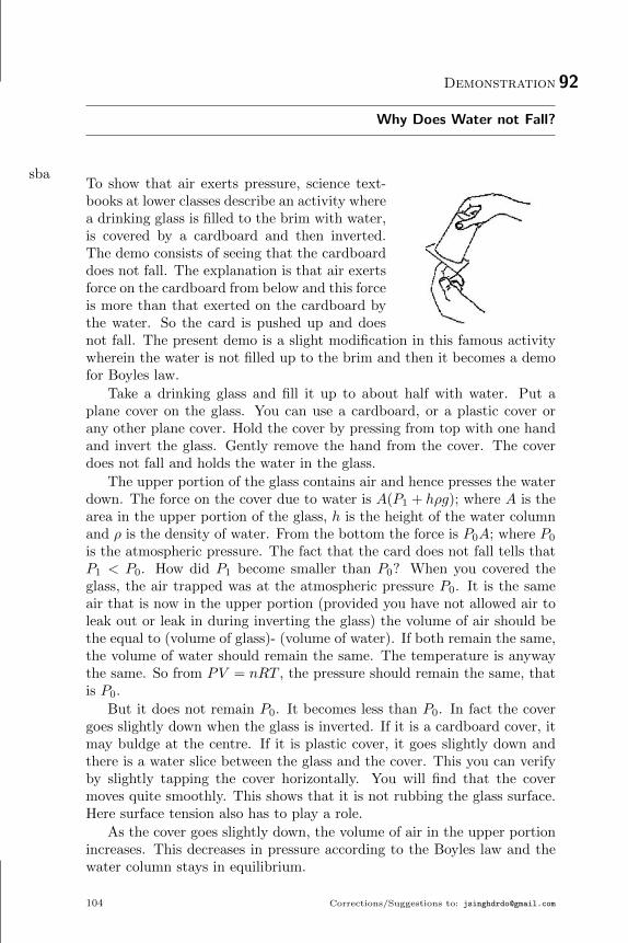
Demonstration 92
Why Does Water not Fall?
sbaTo show that air exerts pressure, science text-books at lower classes describe an activity wherea drinking glass is filled to the brim with water,is covered by a cardboard and then inverted.The demo consists of seeing that the cardboarddoes not fall. The explanation is that air exertsforce on the cardboard from below and this forceis more than that exerted on the cardboard bythe water. So the card is pushed up and doesnot fall. The present demo is a slight modification in this famous activitywherein the water is not filled up to the brim and then it becomes a demofor Boyles law.
Take a drinking glass and fill it up to about half with water. Put aplane cover on the glass. You can use a cardboard, or a plastic cover orany other plane cover. Hold the cover by pressing from top with one handand invert the glass. Gently remove the hand from the cover. The coverdoes not fall and holds the water in the glass.
The upper portion of the glass contains air and hence presses the waterdown. The force on the cover due to water is A(P1 + hρg); where A is thearea in the upper portion of the glass, h is the height of the water columnand ρ is the density of water. From the bottom the force is P0A; where P0
is the atmospheric pressure. The fact that the card does not fall tells thatP1 < P0. How did P1 become smaller than P0? When you covered theglass, the air trapped was at the atmospheric pressure P0. It is the sameair that is now in the upper portion (provided you have not allowed air toleak out or leak in during inverting the glass) the volume of air should bethe equal to (volume of glass)- (volume of water). If both remain the same,the volume of water should remain the same. The temperature is anywaythe same. So from PV = nRT , the pressure should remain the same, thatis P0.
But it does not remain P0. It becomes less than P0. In fact the covergoes slightly down when the glass is inverted. If it is a cardboard cover, itmay buldge at the centre. If it is plastic cover, it goes slightly down andthere is a water slice between the glass and the cover. This you can verifyby slightly tapping the cover horizontally. You will find that the covermoves quite smoothly. This shows that it is not rubbing the glass surface.Here surface tension also has to play a role.
As the cover goes slightly down, the volume of air in the upper portionincreases. This decreases in pressure according to the Boyles law and thewater column stays in equilibrium.
104 Corrections/Suggestions to: [email protected]

References 105
Sometimes few drops of water may go out while inverting. If air hasnot gotten into the glass in this period, the volume of air will increase andhence the pressure will decrease. Sometimes few bubbles of air also getsin. This happens when somewhat larger mass of water comes out duringinversion. In such a case right amount of air will go in which can maintainthe cardboard in equilibrium.
Variant: Do the same with holes in the card. Water does not come outthrough the holes.
References
[1] Source: http://www.vigyanprasar.gov.in/activity_based_
science/Exp6.htm
[2] Video: http://youtu.be/rkfIarmyzmY?list=
PLjVcSEe2pNnZiJpmGp9-iGmjkJzf4QGrX

Demonstration 93
Own Thermometer
pcaShown by Brajesh Dixit ji in Kolkata Meet.
106 Corrections/Suggestions to: [email protected]

Demonstration 94
Saturated Salt Solution
keaObjective: Make concentrated salt solution with 10 g of salt, and calculatethe concentration in g/ml of the solution at the existing temperature of thesolution.
Apparatus: Packet of 10 g salt, 500 ml of water, Beaker of glass, Stirrer,Measuring Cylinder, Thermometer, Syringe
Instructions: The amount of salt is fixed and you have to put minimumneeded water to dissolved it. In case you fail at certain stage you may askfor another packet of 10 g salt only once. Make as accurate measurementsas you can. Write the approximations, you have taken, errors that couldhave gone, your efforts to reduce the error. Write the final value obtainedfor concentration in gram/milliliter of solution. Estimate the uncertainty/error in the measurement. Write the temperature of the solution. Presen-tation is yours. You have to plan for tables, headings, etc.
Corrections/Suggestions to: [email protected] 107

Demonstration 95
Why does Water rise in Burning Candle Experiment?
rbaThe experiment described in the first part isvery famous and is used by many teachers andstudents to show that there is 21% oxygen inair. In this demo experiment I will show thatthe real physics of rising water is very different.
Put a candle vertically in a plate. Light thecandle. Put some water in the plate so thata small lower portion of the candle is in water.The candle keeps on burning. Cover the burningcandle by an inverted glass. The candle goes off and water rises in the glass.How much water will rise in glass depends on the thickness of the candleand how much time you allowed the candle to burn before you covered it.Use a candle and cover it quickly after burning. As the candle goes off,very small amount of water rises in the glass. It could be hardly 5% of thevolume of the glass. Leave this set up as it is and take another plate, puta similar candle, pour water, light the candle and wait for some time. If afan is running nearby put it off. Now cover it with a glass of the same size.This time water rise will be much more.
Now take the third plate and put two candles in it. Pour water in theplate and light all the candles. Wait for some time and then cover both bya glass of the same size as used in the previous trials. This time the waterrise will be very high, may be 40-50%.
What is the Physics of this rising water? When candle burns the airsurrounding the flame becomes hot. The flame itself is very hot gases. Thepressure of this surrounding air is the same as the atmospheric pressure asall air is connected. As pressure remains the same and the temperaturerises the density goes down from the gas law PV = nRT . For a givenvolume n will decrease if T increases. When you cover the candle(s) youtrap this less dense air. As the oxygen is consumed and the candle goesoff, the air (gases in fact) inside the glass cools down. As the number ofmoles n is now fixed, decreasing the temperature will decrease the pressureand this will suck water in the glass. In equilibrium the temperature inthe glass will be the same as the room temperature, the pressure will beP = P0 − hρg, where P0 is the atmospheric pressure and h is the heightwater rises.
If you cover the candle just after the burning, the air trapped is notthat hot. The density is thus not much lowered and hence on candle goingoff the water rise is not much. On the other hand if you burn two contentin air. In fact for each oxygen molecule consumed, you produce a moleculeof CO2 among other products. Also the solubility of CO2 is lower than
108 Corrections/Suggestions to: [email protected]

References 109
that of O2. So there is no question of decrease in pressure inside due toconsuming oxygen.
There is another factor that contributes in rising water in the glass. Athigher temperature the saturation vapour pressure of water is also high. Asthe air in the inverted glass is in contact with water, it will contain saturatedvapour. When the candle goes off and the temperature falls, saturationvapour pressure also decreases and some of the vapour condenses. Thisalso decreases pressure inside and helps in rise of water.
Note that water starts rising only after the candle goes off.
References
[1] Source: http://www.vigyanprasar.gov.in/activity_based_
science/Exph2.htm

Demonstration 96
Boyles law using a syringe and weights
cfaObjective:To study Boyles law using a syringe and weightsIntroduction: Everyone is familiar with Boyle’s law PV = nRT . You willmeasure and vary P and V for a trapped mass of air and see how goodyour system follow Boyles law.Apparatus: A syringe with one end closed and some air trapped in it.An identical extra syringe, Support system for keeping the syringe fixedin vertical position. A pan suspended from the lower end of the syringebarrel, known weights.Information for the students: Suppose, you put a weight W in the pan.The piston will slide down and will stay at some position. Suppose, thepressure inside is P , area of inner cross section is A, Let the weight of thepiston plus the pan is W0. Atmospheric Pressure = P0. For equilibrium,PA+W+W0 = P0A or P = (P0A−W−W0)/A or nRTA
V = (P0A−W0)−W .Thus if you plot 1/V versus W , it should be a straight line.
So, look at the volume with zero weight. Then increase the weight insteps and every time measure the volume. Make a table and calculate 1/Vfor each value. Plot a graph 1/V versus W .
The piston and the barrel will have some friction. The piston can stay atdifferent positions for the same weight. So you have to carefully determinethe volume corresponding to a given weight. One way is to pull the pistona little and release, see where it stays while going up. Then push it a littleand release, see where it stays while coming down. Take the average.Acknowledgement: Developed at Shiksha Sopan
110 Corrections/Suggestions to: [email protected]

Demonstration 97
Boil Water with Hands!
vdaThe objective is to realize that boiling point de-creases with decreasing pressure above the liq-uid surface. Equipment needed are a heater, aconical flask with tightly fitting stopper.
Boiling point of a liquid depends on the pres-sure above its surface. Lower the pressure, loweris the boiling point. Thus you can boil water ata temperature much below the normal boilingpoint if the pressure above its surface is reduced.In this demo we do precisely this. The demo isvery interesting and catches attention of every-one around.
Take some water in a conical flask (say half the volume). The flaskshould be of good quality. I have done the experiment with Borosil flasks.Put the flask on a heater. Let it boil for about 5 minutes. Put off theheater. Now carefully hold the flask from its neck by using a handkerchiefand put stopper in it as early as possible.
The water stops boiling because it is no more on heater. Put somecold water on the flask, especially on the empty portion. The water startsboiling in the flask. Wait for about a minute and the boiling stops. Againput cold water on the flask. The water in the flask again starts boiling.You can repeat this several times.
Why does water boil when cold water is poured on the flask? Wheninitially you boiled the water on the heater, there was no stopper. Vapourgenerated during boiling replaced air and there was largely only the vapourabove the water in the flask. At this stage you fitted the stopper tightlywhich closed any possibility of air entering the flask.
The water has cooled down a little by this time and there is no questionof boiling. Even at the boiling temperature it boils only when heat issupplied to it which is used in conversion of water to vapour. You pouredcold water at this stage. The vapour condensed to water as a result ofcooling due to cold water. This greatly reduced the pressure inside theflask. At such a low pressure, the boiling point of water is quite low and theexisting temperature of water is much larger than this new boiling point.Thus water starts boiling and coverts to vapour. The pressure inside againincreases due to this vapour. Correspondingly the boiling point increasesand the water stops boiling at a certain stage. Then you put cold wateragain. The same process repeats and water boils.
Please take care of accidents. The heater must be a good quality andyou should check that there is no current in the body when the heater is put
Corrections/Suggestions to: [email protected] 111

112 References
on. Handling hot water should be done with extreme care. Hold the flaskfrom the neck only using sufficiently thick layer of cloth (handkerchief).While putting the stopper, the flask should rest on a firm surface. Thoughyou put cold water several times, the lower portion of the flask remainshot. Dont try to hold it from there without checking.
Once the demo is over you may like to open the stopper. This seemsto be the most difficult task. Since the pressure inside remains much lowerthan the atmospheric pressure, it does not come out easily. Heat the flaska little and then take it out if it does not come with mechanical effort.
References
[1] Source: http://www.vigyanprasar.gov.in/activity_based_
science/Exp4.htm

Demonstration 98
Cloud in a Bottle!
xdaPlace a splash (1 teaspoon) of water into theplastic bottle. Light the match and make sureit is burning well, then drop it into the bottle.Quickly screw the cap on, and squeeze the bot-tle with your hand five or six times (for largerbottles you may have to do it slightly more). You should see a cloud formin the bottle, then magically disappear when you squeeze it. Pass thebottle around the audience to give everyone a chance to experience it forthemselves.
Clouds are formed when water droplets in the air cool and then collecton dust particles. In this demonstration, the dust particles were providedby the smoke from the match. The air inside the bottle was cooled byreleasing the pressure after the bottle was squeezed. The temperature ischanged by squeezing the bottle: the amount of air within the bottle isconstant, but squeezing the plastic bottle changes the volume of the gas.Expanding the bottle causes a lowering of the air temperature in this case,enough to cause the water gas to form a liquid the cloud.
Try adding a small amount of food colouring to the water it can helpto increase the visibility of the effect.
References
[1] Related Source: http://www.physics.org/interact/
physics-to-go/cloud-in-a-bottle/
Corrections/Suggestions to: [email protected] 113

Demonstration 99
Measure dew point in your room
efaIntroduction: In the winter nights and early morning the grass feels wetwhen we touch it. As the temperatures dip at this time, the amount ofwater vapour present in the air saturates the air and further cooling resultsin some of the water vapour to condense as a liquid to form the “Dew”.The temperature at which the water vapour is just able to saturate the airis called the dew point.
Once the dew point is known the relative humidity can also be easilycalculated by the relation:
Relative humidity = Saturation vapour pressure at dew point/ Satura-tion vapour pressure at the room temperature.
(Here saturation vapour pressure is the pressure exerted by the vapourwhen the air is saturated by the vapour. Saturation vapour pressure hasbeen measured for various temperatures and tables are available which cangive us its value at the required temperature.)What do you need: Two new steel glasses, cold water bottle, thermometerWhat to do: Put the two glasses side by side.
1. Take out a cold water bottle from the refrigerator. See that waterhas condensed on the surface of the bottle after you take it out of therefrigerator.
2. Now fill one fourth of one glass with normal tap water and put athermometer in the glass.
3. Gradually pour some cold water in the glass and stir. See if there isa difference in the shine of the surfaces of the two glasses.
4. If yes, note the temperature of water in the thermometer.
5. If not, pour some more cold water till you start noticing a differencein the shine of the surface of the glasses. Note the temperature of thewater.
6. This is the “Dew point” of your room.
Why does it happen: Steel is a good conductor of heat. So the temperatureof the water inside the glass and the outer surface of the thin steel glass upto the height of water quickly become same. The air in contact with thesurface cools down as it also attains the temperature of the surface. Whenthe temperature falls just below the dew point, vapour starts condensingand small droplets of water collect on the glass surface making it look alittle foggy. So a careful comparison of the shininess of the two glasses, onewith the cold water and the other empty, gives a fair measure of the dewpoint.
114 Corrections/Suggestions to: [email protected]

Demonstration 100
Coffee cup calorimetry
ffaIntroduction: According to the laws of nature heat is transferred from ahot body to a cold body when they are brought in contact. The transferof heat continues till they attain same temperature . The amount of heatloss incurred by the hot body is equal to the amount of heat gained by thecolder body. This is also referred to as the Principle of Calorimetry.
Here a thermocol cup is used as a container to do the calorimetery andestimate the specific heat capacity of aluminium.What do you need: Coffee heater, thermocol cup, thermocol lid, aluminiumblock , water, weighing balance, thermometerWhat to do:
1. Measure the mass of the aluminium block using the weighing balanceand note its mass as MAl.
2. Put the small aluminium block in normal tap water.
3. Measure its temperature and note it as T1.
4. Now fill the coffee cup with 100 ml of water and put the coffee heaterin it and cover it.
5. Put the thermometer in the cup from the hole in the thermocol lid.
6. Switch on the heater.
7. When the thermometer shows 70 C (T2), switch off the heater andremove it.
8. Quickly take out the aluminium block from the normal tap water,wipe it and put it in the thermocol cup.
9. Close the lid and stir the water with the thermometer.
10. See the temperature of the thermometer falling till it becomes con-stant after some time. Note this temperature as T .
11. Using the formula of calorimetery find the specific heat capacity ofaluminium
MAlSAl(T − T1) = MwSw(T2 − T )
Here Mw = Mass of 100 ml of water is 100 g (density 1 g/ml) andSw = Specific heat of water is 1 cal/g/C
Discussion: The specific heat capacity of Aluminium estimated by thismethod is close to the actual value. This is because thermocol is a poorconductor of heat and also it is very light (less mass) so the heat transferoccurs mainly between the water and the aluminium block.
Corrections/Suggestions to: [email protected] 115

Demonstration 101
See Convection Current in Air
pbaTake a kerosene lamp with some kerosene andwick in place or a candle. Take a cardboardbox, like a shoe box. Place it in a way thatthe opening side is vertical and is towards you.Cut two holes on the top cover of the box sothat the glass covers of the lamp can be fittedin these. Put a lamp inside the box below oneof the holes. One of the glass covers should gothrough the hole and fit with the lamp. Let mecall this Cover-1. Put another glass cover in theother hole. I will call it cover-2. Close any gap remaining between the glasscovers and the cardboard top cover.
Light the lamp, put it in place and close the box. Light an incensestick. Where is the smoke going? It goes up. That is the natural tendencyof smoke. Put the stick near the glass cover-1. The smoke goes up. Nowput the stick near the glass cover-2. Here is the real climax. The smoke ispulled down into the glass cover-2 and it come out from the glass cover-1.
Why is the smoke dragged into the glass cover against its natural ten-dency to go up? This is because the burning wick of the lamp producedhot gases which rose up and went out through the glass cover-1. To fill thevoid, air should rush in. The only path available for fresh air is through theglass cover-2. So convection current is set up where air from outside goesinto cover-2, goes into the box, and then to the wick area. The hot gasesformed there go up and come out of cover-1. When the stick is placed nearthe cover-2, smoke is dragged by the air current that already exist there.The flow path of smoke is just the path of convection current.
References
[1] Source: http://www.vigyanprasar.gov.in/activity_based_
science/Exph5.htm
[2] Video: http://youtu.be/5ntWE73Dcuc?list=
PLjVcSEe2pNnZiJpmGp9-iGmjkJzf4QGrX
116 Corrections/Suggestions to: [email protected]

Demonstration 102
Conduction of Heat
bcaTake a rod or flat strip of a metal, say of alu-minium or iron. Fix a few small nails on thestrip with the help of wax. These pieces shallbe at nearly equal distances. Clamp the rod toa stand. If you do not find a stand, you can putone end of the rod in between bricks. Now, heatthe other end of the rod and observe.
What happens to the nails? Do these begin to fall? Which nail fallfirst? Do you think that heat is transferred from the end nearest to theflame to the other end?
References
[1] Video: http://youtu.be/7Wv40DH7nQ0?list=
PLjVcSEe2pNnZiJpmGp9-iGmjkJzf4QGrX
Corrections/Suggestions to: [email protected] 117

Demonstration 103
Solar Heating
bbaTake two cardboard boxes of the same size.Paint the inner walls of one white and paintthe other black. Cover the top of the box withglass and keep the boxes in the sun. The glasstops will allow sunlight to enter the boxes. Af-ter 15 minutes or so, check the temperature ofeach box. You will find the box with black innerwalls is at a higher temperature.
Alternate: You can do this activity by paint-ing outer walls of cold drink cans.
References
[1] Source: H.C. Verma, Foundation Science Physics for Class 10 (4thed.), Page 115, Bharati Bhawan, 2011
118 Corrections/Suggestions to: [email protected]

Demonstration 104
Boiling Water in Paper Cup
wdaYou can boil water in a cup made of paper.Make a paper cup and fill it with water. Placethis cup on the flame carefully. You will be sur-prised that paper does not burn. Slowly watertemperature increases and it may start boiling.This demo explain conduction of heat.
References
[1] Related Source: PDF File http://goo.gl/QjSbmM
Corrections/Suggestions to: [email protected] 119


Part V
Electromagnetism
121


Demonstration 105
The Rotating Straw
vba
As we know, by rubbing or induction electriccharge can be produced. By combing your hairyou must have tried to attract small pieces ofpaper. You must also be knowing that chargesare of two types - positive charge and negativecharge. Like charges repel while unlike chargesattract each other. We shall see this with thehelp of an interesting experiment.
Take a plastic bottle whose cap is plane.Take two drinking straws and by holding themfrom one end rub them well two or three times with the help of a handker-chief. Now, place one of the straws on the top of the bottle cap in such amanner that it remains parallel to the ground and its middle portion sitson the top of the cap. Now take the other straw, holding it from one endbring it near the first straw. As soon as the second straw is brought nearthe straw resting on the bottle, the latter moves away from the former byrotating on its resting point. If we keep moving the hand held straw in acircular manner towards the straw on the bottle cap, the latter also con-tinuously keeps getting away. While doing so it also rotates presenting avery interesting view of repulsion. Now, instead of the second straw bringthe handkerchief which was used for rubbing the straws, towards the firststraw. The first straw now starts getting attracted towards the handker-chief. Moving the handkerchief away from the straw in a circular manner,the straw also keeps moving towards the handkerchief while making a cir-cular rotation.
When both the straws are rubbed with a handkerchief, the same kindof charge is developed in them while the opposite charge is produced in thehandkerchief. In the first case, as both the straws hold the same kind ofcharge they repel each other and so the straw resting on the bottle movesaway from the hand held straw. In the second case as the charge on thehandkerchief has a sign opposite to that on the straw, the handkerchiefand the straw attract each other, therefore, the straw on the bottle movestowards the handkerchief.
The place where the straw rests on the bottle the friction between thecap and the straw should be least there, so that the straw is free to rotateon the cap.
Corrections/Suggestions to: [email protected] 123

124 References
References
[1] Source: http://www.vigyanprasar.gov.in/activity_based_
science/Exp7.htm
[2] Video: http://youtu.be/BC-FR3lO6UY?list=
PLjVcSEe2pNnZiJpmGp9-iGmjkJzf4QGrX

Demonstration 106
Bending of Water Stream due to Electrostatic Charges
aeaThis is an excellent demonstration for electro-static charges. Make a small hole at the bottomof a water bottle. Make sure that a clear streamof water comes out when bottle is filled withwater. The hole should not be too small or toobig. Rub a plastic scale with cloth and bringit close to the stream (near the top portion).You will observe that stream bends towards thescale. This demo shows the concept on inducedcharges (water is a polar molecule) and electrostatic attraction.
References
[1] Youtube Video https://www.youtube.com/watch?v=VhWQ-r1LYXY
Corrections/Suggestions to: [email protected] 125

Demonstration 107
Electrostatics of Hanging Balloons
ceaThis demo shows Coulomb attraction/repulsionand concept of induced charges.
126 Corrections/Suggestions to: [email protected]

Demonstration 108
Which Direction is Electric Field?
fcaThis experiment is based on this video of Dr. HC Verma: https://www.
facebook.com/photo.php?v=454642061280499&set=vb.100002041261681&type=
3&theater
References
[1] HC Verma Video: https://www.facebook.com/photo.php?v=
454642061280499&set=vb.100002041261681&type=3&theater
Corrections/Suggestions to: [email protected] 127

Demonstration 110
Electric potential in a capacitor
teaObjective: To study the variation of electric potential in a capacitor.Apparatus: A plastic box with two aluminium plates which can be held at adistance and parallel to each other, a battery or power supply, multimeter,graph paper etc.Introduction: The textbook talks of large parallel plate capacitors in whichthe electric field is uniform in the space between the plates and is zerooutside. In finite capacitor, fringing of field makes the field look differentnear the ends. In this experiment you study the potential variation in andaround the capacitor,Experiment: Place the plates in the box and fill the box with water up toabout half the height. Connect the battery to the plates though a switch.Connect the common of multimeter to the plate with battery negative.Make the mode to be DC Voltage. Now wherever you put the other probeof the multimeter, you will get the potential of that point with respect tothe negative of the capacitor.
Measure the potential Perpendicular to the plates in three regions (a)near the middle, near of the length of a plate, (c) at the edge. Eachtime measure it at a regular interval of say 5 mm and present the data ondistance from the negative plate and the potential there.
Measure the potential parallel to the plates in three regions (a) near themiddle, near of the width of a plate, (c) close to a plate. Each time measureit at a regular interval of say 5 mm and present the data on distance fromthe negative plate and the potential there.
Make closer observations close to the plates as there could be sharpervariation.
Draw graphs for these variations.Questions:
1. Is the electric field components perpendicular to the plates constanteverywhere in the capacitor?
2. Is the electric field components parallel to the plates zero everywherein the capacitor?
Acknowledgement: Idea from textbook, verified by Dr. Sudeep Bhattachar-jee, IITK
Corrections/Suggestions to: [email protected] 129

Demonstration 111
Playing with capacitors made from kitchen Utensils
gfaIntroduction: A capacitor is a combination of two conductors separatedby a thin insulating material (called the dielectric). It can be charged byconnecting the two conductors to a battery. The charge required to createa potential difference of 1 Volt between its conducting plates is called thecapacitance of the capacitor. In this demonstration we will make capacitorswith kitchen utensils and measure their capacitance in many combinations.What do you need: Two similar flat bottomed steel thalis, wooden caromboard coins, three similar steel glasses, polythene sheet, newspaperWhat to do: Thali capacitor:
1. Invert a steel thali and keep it on a table such that a small portionof it is over the edge of the table.
2. Attach a crocodile clip from below to the protruding portion of thethali and connect a copper wire to the clip.
3. Now put three carom board coins on the thali and place another thaliover it (face up).
4. Attach another crocodile clip to the upper thali and connect a copperwire to the clip.
5. Connect the two copper wires to an LCR meter.
6. Measure its capacitance.
7. Put a newspaper in the gap between the two thalis and again measureits capacitance.
The capacitance shows a value in picofarads which increases when anewspaper is inserted in the air gap
Glass capacitor:
1. Wrap a steel glass (glass 2) with a polythene sheet and put it insideanother steel glass(glass 1)
2. Attach crocodile clips with copper wires connected to them to therims of the two glasses.
3. Connect the two copper wires to the LCR meter and measure thecapacitance(call it C1)
4. Wrap another glass(glass 3) in a polythene sheet and put it insideglass 2
5. Attach crocodile clip with copper wire connected to it to the rim ofglass 3
6. Now connect the wires of glass 1 and glass 3 to the LCR meter. Leavethe wire of glass 2 free.
130 Corrections/Suggestions to: [email protected]

131
7. Measure the capacitance(call it C2)
8. Connect the wires of glass 1 and 3 and measure the capacitance be-tween this common terminal and glass 2(call it C3)
See that the capacitance C2 is almost half the capacitance C1 and thecapacitance C3 is almost double the capacitance C1. All the capacitancesmeasured are in picofarads.Why does it happen: In the arrangement made with the thalies, the steelthalis are the two conductors and placing carom board coins creates an airgap which acts as the dielectric. Hence the arrangement acts as a capacitor.Putting paper in the air gap increases the capacitance as the dielectricconstant of paper is bigger than air. Capacitance C of the capacitor isgiven by the expression
C = Kε0A/d
Where ε0 is the permittivity of free space, A is the area of the conductors,d is the distance between the two plates and K is the dielectric constant ofthe dielectric between the conductors. For air K = 1 and for paper K > 1.
In the arrangement made with steel glasses, the steel glasses are thetwo conductors and the polythene acts as a dielectric. Hence it becomesa capacitor. The capacitance C2 is almost half of C1 as the arrangementmakes it a series combination of two almost identical capacitors. The capac-itance C3 is double of C1 as the arrangement this time makes it a parallelcombination of two capacitors.
The equivalent capacitance Ceq of N identical capacitors each of capac-itance C is given by, Ceq = NC in series combination and Ceq = C/N inparallel combination.

Demonstration 112
Charging and discharging capacitors
hfaIntroduction: Capacitor is a very important component of many devices.When connected to a battery, the capacitor stores electrostatic energy.This energy is in the form of charge on its plates which raises the potentialdifference between the plates. When required, this capacitor can releasethis stored energy and gets discharged.
What do you need: Two capacitors of high capacitance say 1000 µF, ahigh value resistor say 30 kΩ, a LED, a 9 V battery.
What to do:
1. Connect the capacitor to the battery through the resistor.
2. Since the capacitor is electrolytic capacitor, see that the positive ofthe capacitor is connected to the positive of the battery.
3. Allow it to charge for more than a minute.
4. Now remove the battery and connect the capacitor to an LED throughthe resistor. Again remember to put the positive of the capacitor tothe longer lead of the LED.
5. See that the LED glows very brightly, but gradually the brightnessbecomes less. Note the time for which the LED glows quite brightly.This gives a rough estimate of the time constant. See how much itdiffers from the product of RC.
6. Now repeat the whole process with two capacitors in series.
7. Note the time constant for this. See that the measured time constantis less
8. Again repeat the process with two capacitors in parallel
9. Note the time constant. See that the time constant has increased.
Why does it happen: When a capacitor in series with a resistor is con-nected to a dc source, opposite charges get accumulated on the two platesof the capacitor. We say the capacitor gets charged. The time taken tocharge it to 63% of the maximum charge is called the time constant of thecapacitor. It is equal to the product of capacitance and resistance. If thevalue of the capacitance and resistance is large, the time constant is largeenough to be measurable easily without the use sophisticated instruments.
If this capacitor is now disconnected from the power supply and itsplates are connected to a LED through the resistor, the capacitor will getdischarged. In this process a current flows through the LED and it glows.In one time constant t = RC, 63% of the total charge of the capacitor isneutralized and the current drops to 37% of the maximum. The intensityof the glow of the LED is maximum in the beginning and then gradually
132 Corrections/Suggestions to: [email protected]

133
decreases. In one time constant the glow decreases significantly. This timecan be roughly estimated by us and it gives a fair idea of the time constant.
When two capacitors are put in series, capacitance decreases so the timeconstant decreases. When two capacitors are put in parallel, capacitanceincreases so the time constant increases.

Demonstration 113
Verification of Ohm’s Law
paa
AA B
VTake four or five dry cells, a thin wire (AB),a voltmeter, an ammeter, a plug key and somethick connecting wires. Connect the circuit asshown in figure, using one cell. The plug keyallows you to switch off the current when notrequired. The wire becomes quite hot when current passes through it forsome time. This drains the cell as well. Therefore, insert the key into theplug to switch on the current only when taking measurements.
The ammeter measures the current i through the circuit, and the volt-meter measures the potential difference V between the ends A and B ofthe wire. Note these values. Now, connect two cells in series in the circuit.You will find that the reading of the voltmeter increases, indicating thefact that a larger potential difference has been applied across the wire AB.You will also find that the reading of the ammeter increases as well. Notedown the new values of V and i. Repeat the experiment by connecting inseries three cells, four cells, and so on. In each case measure the potentialdifference and the current. If you calculate V/i for each case, you will findthat it is almost the same. So, V/i = R is a constant, which is anotherway of stating Ohm’s law. Here, R is resistance of the wire AB. If you plota graph of the current of the current i against the potential difference V ,it will be a straight. This shows that the current is proportional to thepotential difference.
References
[1] Source: H.C. Verma, Foundation Science Physics for Class 10,Page 63, Bharati Bhawan
134 Corrections/Suggestions to: [email protected]

Demonstration 114
Series Connection of Resistors
qaa
AR1 R2 R3
VYou can use different kind of bulbs as resistorsin this activity. Connect three resistors of re-sistances R1, R2 and R3 to an ammeter, a celland a plug key, as shown in figure. The threeresistors are connected in series. Close the keyand note the ammeter reading. Now connectthe ammeter between R1 and R2 and note the reading. Similarly, placethe ammeter between the other circuit elements and measure the current.You will find that the value of the current is the same everywhere in thecircuit. So, the same current passes through the three resistors.
Now, connect a voltmeter in the circuit, as shown in figure. Close thekey and note the potential difference V across the series combination ofresistors. Then connect the voltmeter across R1 and note the reading V1.Similarly, connect the voltmeter across R2 and R3, one at a time, andmeasure the potential difference V2 and V3 across them. You will find thatV = V1 + V2 + V3.
References
[1] Source: H.C. Verma, Foundation Science Physics for Class 10,Page 65, Bharati Bhawan
Corrections/Suggestions to: [email protected] 135

Demonstration 115
Parallel Connection of Resistors
raa
Ai2 R2
i1 R1
i3 R3
VConnect three resistors (R1, R2 and R3), an am-meter, a cell and a plug key, as shown in figure.Close the key and note the ammeter reading.This gives the current i in the circuit. Now,connect the ammeter in the branch of the circuitthat has R1 and note the reading. This gives thecurrent i1 through the branch. Similarly, placethe ammeter in the branches containing R2 andR3, and measure the current i2 and i3 respec-tively. You will find that the current i gets divided into the branches suchthat i = i1 + i2 + i3.
References
[1] Source: H.C. Verma, Foundation Science Physics for Class 10,Page 66, Bharati Bhawan
136 Corrections/Suggestions to: [email protected]

Demonstration 116
Wheatstone bridge using electric bulbs!
ucaA wheatstone bridge is constructed using lightbulbs. When plugged in, the four outer lightbulbs light while the central bulb doesn’t. Thesame setup may be used to series and paral-lel combinations of bulb. This is a good demo
to eliminate misconception regarding P = V 2
Rand/or P = I2R.
Hazard: Be careful while working with 220 V.
References
[1] Video: http://youtu.be/dQmC2PF9KhE?list=
PLjVcSEe2pNnZiJpmGp9-iGmjkJzf4QGrX
Corrections/Suggestions to: [email protected] 137

Demonstration 117
Measure the Resistance of an Electric Bulb
deaIntroduction: An ordinary bulb has a thintungsten filament. The power rating P and volt-age rating V of a bulb is quoted above the bulb.The resistance of the bulb is found theoreticallyusing the formula R = V 2/P . In this demon-stration we find the resistance of such a bulbusing a multimeter and compare it with the the-oretically calculated value. The results give aninsight into the temperature dependence of re-sistance.Equipment: A 220 V AC source, 100 W bulb,a bulb holder, a multimeter and connectingwires.Procedure:
1. Put the bulb in the bulb holder.2. The two terminals of the bulb are now connected to the wires of the
holder.3. Connect these two wires to the multimeter and measure the resistance
of the bulb. Note this reading.4. Now calculate the resistance of the bulb using the specifications of
the power and voltage rating given on the bulb. Again note thisreading. Do you notice a difference in the two readings. Why? Isthe multimeter defective? Is the formula used for calculation of theresistance wrong?
Discussion: The resistance of the bulb comes out to be 484 Ω after calcu-lations. But the multimeter reading shows a value of less than 50 Ω. Well,the multimeter is not defective which we prove by measuring a known resis-tance. The formula used is also perfectly right. But there is one thing wemiss in this whole exercise. Resistance of a conductor increases with tem-perature. When we measure the resistance of the bulb with the multimeter,the filament is at the room temperature(about 30 C). But using the for-mula, the obtained resistance is the resistance of the bulb in full glow i.e.when it is connected to a 220 V and has attained a temperature at which itstarts giving light. This temperature is around 3000 C. So the calculatedresistance is much higher than the resistance shown in multimeter.
The resistance of a conductor varies with temperature which can beexpressed as RT = R0[1 + α(T − T0)], Where RT is the resistance at thetemperature T and R0 is the resistance at the temperature T0 (generallythe room temperature), α is called the temperature coefficient. The tem-perature coefficient of tungsten is 4.5× 10⁻³ /C.
138 Corrections/Suggestions to: [email protected]

Demonstration 118
Magnetic Line of Forces
saaFix a white sheet of paper on a horizontal sur-face and keep a strong bar magnet on it. Placea small magnetic compass at various points nearthe magnet, and note the direction in which itsneedle comes to rest at these points. Figureshows these directions at points such as A, B, C, D, E and F. The di-rection of the needle at a point gives the direction of the magnetic field atthat point.
Place the compass close to the north pole of the magnet. Once theneedle comes to rest, look from above, and with a pencil, mark the positionof the north pole of the needle on the sheet (i.e., mark the point closest tothe north pole). Now, shift the compass ahead in such a way that after theneedle comes to rest, its south pole is at the point marked for the previousposition of the north pole. Mark the position of the north pole of the needleat the new location. Keep moving the compass ahead in this way till youreach the south pole of the magnet. Then join all the points marked onthe paper with a smooth curve.
Repeat the whole process to get some more curved lines. Each timestart from a new position near the north pole of the magnet. If you drawtangent at any point on these lines, the magnetic field at that point will bealong the tangent.
A line such that the tangent at any point on it gives direction of themagnetic field at that point is called magnetic field line or magnetic lineof force. Figure shows some magnetic field lines due to a bar magnet. Anarrow showing the direction of the field at a point has been drawn on eachfield lines. Remember that the field lines are imaginary. They just help usvisualize magnetic field.
You can see magnetic field lines with the help of iron fillings too. Placea glass or clear plastic sheet over a bar magnet. Sprinkle some iron fillingsover the sheet, and gently tap the sheet. The iron fillings will arrangethemselves to show the magnetic field lines.
References
[1] Source: H.C. Verma, Foundation Science Physics for Class 10,Page 86, Bharati Bhawan
Corrections/Suggestions to: [email protected] 139

Demonstration 119
Motion of Charged Particles in Magnetic Field
eeaIntroduction: When charged particles movein a magnetic field they experience a force.Thisforce is referred to as the magnetic Lorentz forceand acts perpendicular to the motion of the par-ticle. When this topic is taught, the above men-tioned charged particles are taken to be elec-trons, protons or alpha particles and the students have to visualize theirmotion when they are projected in the magnetic field. In this demonstra-tion ions of an electrolyte are made to move in the magnetic field of apermanent magnet. The design allows the whole liquid mass to move incircular motions which can be seen.Equipments:A flat bottomed round plastic/glass cap of around 2 inchdiameter or a petri dish, crocodile clips, salt water, battery eliminator,ring magnet, copper wires.Procedure:
1. Keep the plastic cap on the ring magnet.2. Then remove the enameling of around 7 inch copper wire and put it
just inside the periphery of the cap.3. Connect the copper wire to the negative terminal of the battery elim-
inator with the help of a crocodile clip. Pour salt water in the plasticcap so that the copper wire gets immersed in it.
4. Now connect the positive terminal of the battery eliminator to acrocodile clip with the help of a copper wire.
5. Hold this crocodile clip vertically in the centre of the plastic cap suchthat a small metal portion of the clip is inside the salt water.
6. Switch on the battery eliminator and apply a voltage of 6 V.
See that the salt water in the plastic cap gradually starts rotating in clock-wise direction. After a while the water becomes dark and the rotation ismuch more visible. Interchange the terminals of the battery eliminator.See that the water now starts rotating anticlockwise direction. Now invertthe ring magnet under the cap, water starts rotating again in clockwisedirection.Discussion: The arrangement made in the plastic cap makes it a voltame-ter. The salt water acts as the electrolyte. Copper wire which is at theperiphery and the metal portion of the crocodile clip, act as the two elec-trodes. The sodium chloride in water becomes ionized. When the poweris switched on, a radial electric field is set up and the sodium and chlorideions start drifting in the influence of this field. The ring magnet belowthe cap produces a magnetic field in the vertical direction. The ions aremoving in the horizontal plane of water. So their motion is perpendicular
140 Corrections/Suggestions to: [email protected]

141
to the magnetic field. They experience a force which causes them to movein a circular path. This tendency of the ions to move in a circular pathcauses the whole water mass to rotate with it.
Magnitude of the magnetic Lorentz force F on charged particles movingperpendicular to the magnetic field is given by F = qvB, where q, v andB are the magnitudes of charge, velocity and magnetic field respectively.This force provides the centripetal force to make the charged particle movein circular path.

Demonstration 120
Magnetic Effect of Current
taaPlace a magnetic compass on a plastic orwooden block, away from all magnetic material.When the compass needle comes to rest, fix awire over the compass, parallel to the needle.Connect the wire to a battery through a switch,as shown in figure. Close the switch to pass acurrent through the wire. The compass needlewill get deflected, and comes to rest at right angles to its original position.If the direction of the current is from south to north, the north pole of theneedle will come to rest pointing west.
Now, hold the compass above the wire. The needle will get deflected inthe opposite direction. The direction of deflection will also change if youreverse the direction of the current in the wire by interchanging the batteryconnections. If you switch off the current in the wire, the needle will goback to its original position.
Make sure that you pass a current through the wire only for short periodof time (say, 5 seconds). Allowing current to pass through the wire for longwill heat the wire considerable and also drain the battery rapidly.
References
[1] Source: H.C. Verma, Foundation Science Physics for Class 10,Page 87, Bharati Bhawan
142 Corrections/Suggestions to: [email protected]

Demonstration 121
Magnetic Field due to a Straight Conductor
uaaFix a long stiff wire AB upright in a piece ofcardboard kept horizontally. Connect the wireto a battery through a switch, as shown in fig-ure. Use long connecting wires to keep the bat-tery and the switch away from the cardboard.Now, place a compass on the cardboard. Start the current by closing theswitch. The compass needle will get deflected, and its direction will showthe direction of the magnetic field at that point.
Mark the position of the north pole of the needle on the cardboard.Shift the compass ahead so that south pole of the needle lies at the pointmarked for the previous position of the north pole. Mark the new positionof the north pole. Repeat the procedure till you reach the point fromwhere you started. Join all the points by a smooth curve to give a fieldline. Similarly, draw other field lines at different distances from the wire.Draw arrows on the lines to show the direction of the magnetic field. If thecurrent is strong, say about 2 A, the lines will be nearly circular. If thecurrent is weak, it will produce a weak magnetic field. Then the earth’smagnetic field will have greater effect on the field lines, and they will notbe circular.
If the direction of the current is reversed, the field lines will still becircular, but the directions of the field lines will be reversed. This means,the north pole of the needle will point in the opposite direction.
You can also sprinkle some iron fillings on the cardboard to see howthe field lines are arranged. While a current is passing through the wire,gently tap the cardboard. The iron fillings will get arranges in concentriccircles, suggesting that the field lines due to a current passing through astraight wire are circular.
References
[1] Source: H.C. Verma, Foundation Science Physics for Class 10,Page 88, Bharati Bhawan
Corrections/Suggestions to: [email protected] 143

Demonstration 122
Making of an Electromagnet
vaaWind a solenoid directly over an iron bolt ornail, using 5− 8 feet of thick enamelled copperwire. (In these wires, the enamel coating actsas an insulator.) Use adhesive tape to keep theturns in place. Scrape off the enamel from thefree ends of the wire, and connect them to abattery through a switch. Now, close the switch.The bolt will attract iron and steel objects placed near it. If you turn thecurrent off, the bolt will no longer attract these objects.
References
[1] Source: H.C. Verma, Foundation Science Physics for Class 10,Page 90, Bharati Bhawan
144 Corrections/Suggestions to: [email protected]

Demonstration 123
Magical Swing
waaConnect the ends of a small, thick aluminium orcopper wire to two long, thin wires. Use thesewires to hang the aluminium wire from a sup-port. Connect the wires to a battery and switch,as shown in figure. Place a horseshoe magnet asshown. The aluminium wire should swing freelybetween the poles.
Turn on the switch to pass a current. The aluminium wire will move,showing that the magnetic field exerts a force on it. Note the directionin which the wire moves. Turn the magnet upside down to change thedirection of the magnetic field. Now, when a current is passed throughthe wire, the wire moves in the opposite direction. The direction in whichthe wire moves also changes if you change the direction of the current byinterchanging the connections to the battery.
(In this activity you can also use a disc or ring magnet kept below thewire. And if you have a bar magnet, place it vertically, below the wire.)
Puzzle: This set-up can be used as an interesting puzzle. Ask thestudents to find poles (north/south) of ring magnet by using this set-up.This will eliminate very confusing Fleming’s right hand rule/ left handrule/ screw rule etc.
References
[1] Source: H.C. Verma, Foundation Science Physics for Class 10,Page 91, Bharati Bhawan
Corrections/Suggestions to: [email protected] 145

Demonstration 124
Attraction and Repulsion between Current Carrying Conductors!
vcaTwo parallel wire carrying current in same di-rection attracts each other and in opposite di-rection repels each other. Make two coils (ra-dius 2 cm, number of turns 100). Hang thesewith plane of coils parallel to each other. Con-nect both to a battery/power supply. See at-traction/repulsion between them by changing direction of current.
146 Corrections/Suggestions to: [email protected]

Demonstration 125
Current detector
mfaIntroduction: If a magnet is kept near a currentcarrying wire, it tries to align itself in the direc-tion of the magnetic field produced by the cur-rent. This fact is used to make a device whichcan detect currents. In this demonstration wemake one such current detector.What do you need: A coil made of about 30turns of enameled copper wire fixed on a plastic stand using amcil, Amagnetized needle, connecting wires and a battery (1.5 V).What to do:
1. Suspend the magnetized needle in the middle of the coil with a thread.
2. See that, in equilibrium position, the needle, points in the north southdirection. Why?
3. Now connect the two ends of the coil to the battery.
4. The needle swings and comes to rest in a direction perpendicular tothe plane of the coil. Why?
Why does it happen: When current passes through a coil it establishes astrong magnetic field which points in a direction perpendicular to the planeof the coil at the center of the coil. So the needle swings in the directionof the magnetic field.Point of discussion: In the absence of the current in the coil, the needleis visibly affected by the earths magnetic field but when current flows inthe coil, the magnetic field of the coil is so strong that the effect of earthsmagnetic field on the needle is not visible.
Corrections/Suggestions to: [email protected] 147

Demonstration 126
Poles of a Ring Magnet
ybaTake a ring magnet. Hang it with a thread.Find and mark the north pole and the southpole of this magnet. Take another ring magnetand do the same. Verify by observing attractionbetween opposite poles and repulsion betweensame poles.
148 Corrections/Suggestions to: [email protected]

Demonstration 127
Magnetic Shielding
beaHang a needle vertically by using a magnet withphysical separation between two. Place non-magnetic material between the needle and mag-net. Nothing happens. Now place magneticmaterail like iron plate. The needle falls down.This demonstarte the magnetic shielding causedby the iron plate.
Corrections/Suggestions to: [email protected] 149

Demonstration 128
Magnetic field lines for a given magnet
zeaObjective:To draw magnetic field lines for a given magnet.Introduction: Magnetic field line gives the direction of magnetic field atthe points from which these lines are drawn. To get the magnetic fielddirection, one can use a small compass which rests in the direction of theresultant magnetic field (horizontal component). To get the field line dueto magnet only, one should ensure that the compass needle rests alongnorth-south direction. In this case, the torque due to the earths field iszero.Apparatus: A magnet, A drawing board or any board of size about 12 inchby 18 inch A compass, Two A4 size paper sheets or an A3 paper sheet,Two wooden stands with a long thread tying both, Cellophane tapeInformation for the students: You have to draw magnetic field lines for thegiven magnet. Place the paper sheet on the board and fix the corners usingthe tape. Put the two wooden stands with thread stretched between themat sufficient distance between them so that the drawing board can easilyrotate under the thread. Place the magnet in the middle and tape it.
Draw 8 field lines starting from one end of the magnet, 4 on each sideof it. Make sure, you make the compass in north south direction beforemarking the end positions to avoid torques from earth’s magnetic field.Acknowledgement: Developed at Shiksha Sopan
150 Corrections/Suggestions to: [email protected]
Demonstration 129
Force law between two magnets as a function of their separation
afaObjective:To explore force law between two magnets as a function of theirseparation.Introduction: The force between two magnets does not have a simple rela-tion with distance. This is because both the magnets have two poles andso four forces are involved for each magnet. And this depends on the geom-etry of the magnets. You will investigate the force between two cylindricalmagnets in a particular geometry.Apparatus: A sensitive spring balance, a suspension rod, a hook with along cylindrical magnet A attached to it, a long plastic rectangular tube,a magnet B attached to a long rod.Information for the students: The spring balance is calibrated in newtons.On this scale 0.1 Newton has a physical length of 1 cm. Fix up the suspen-sion rod horizontally and suspend the spring balance from it. At the lowerend suspend the magnet A.
Fix the plastic tube around the lower part of the spring balance. Themagnet A goes into the tube.
Read the pointer on the balance. This actually gives the weight of themagnet A. Take this position as X (force between the magnet B is zero).Insert the magnet B in the plastic tube from below by holding the longrod.
Gradually raise the rod and see when the sping balance pointer movesup by say 1 division so that you can read it. The plastic tube has a graphstrip attached to it. Measure the facing ends of A and B on this scale. Thisgives separation between the magnets. Note the reading x1 of the balancepointer. X − x1 gives the force between the magnets.
Make table to note the readings of magnet B on the graph strip andthe corresponding balance reading. From these two readings you can findthe decrease in separation between the magnets. Remember 0.1 newton ofgraduation on the balance has physical length of 1 cm. The balance reading(with X) gives the force. Make 8 to 10 readings till the balance readinggoes out of scale.
Draw a graph between the force between the magnets versus separationbetween their facing poles. Can you suggest an algebraic relation betweenthe two.Acknowledgement: Developed at Shiksha Sopan
Corrections/Suggestions to: [email protected] 151

Demonstration 130
Effect of Temperature on Magnetic Materials
ddaA Magnet. Heater Coil. Attraction. Pass cur-rent through heater coil. The temperature ofheater coil increases and it looses its ferromag-netic properties. At this time, the magnet fallsdown.
ViBha, Hyderabad developed this set up tooperate at 6− 12 V. Made stand using a 4 in by6 in piece of plywood. A 30 cm scale was fixedon one end to hold thread attached to the mag-net. A 15 cm scale was cut into two pieces andthese pieces are attached on the side of stand.This become holder for heating element. Theheating element is a 3 cm piece of 1000 watt heater coil. Other things canbe fine tuned.
Hazard: Do not touch heating element when connected to powersource. It becomes red hot and may harm you.
Note: Dr Ajay Mahajan demonstration. Place a needle (paper clip)close to the magnet with a little horizontal separation between them. Heatthe needle. The needle fall after when it become hot.
152 Corrections/Suggestions to: [email protected]

Demonstration 131
Faraday’s Law of Electromagnetic Induction
xaaConnect the ends of a coil to a galvanometer.Since there is no current in the coil, the needleof the galvanometer will be at the zero mark.Now, bring a bar or rod magnet sharply towardsthe coil. The galvanometer needle will get de-flected in a particular direction. When the mag-net comes to rest, the needle comes back to its zero position, showing thatthe current in the coil has stopped. Now, move the magnet away from thecoil. The needle will get deflected again, but this time, in the oppositedirection. This shows that the direction of the current has reversed. Youwill also find that the direction of the current depends on the pole of themagnet facing the coil while the magnet is moving.
What happens if we move the coil instead of the magnet? Fix the coilto a wooden block, and move it sharply towards the magnet. You will findthat as long as the coil moves, there is a current in the coil, as indicatedby the deflection of the needle of the galvanometer. And if you move thecoil away from the magnet, the needle of the galvanometer gets deflected inthe opposite direction. There is no deflection, i.e., no current, when bothof them are at rest.
References
[1] Source: H.C. Verma, Foundation Science Physics for Class 10,Page 93, Bharati Bhawan
Corrections/Suggestions to: [email protected] 153

Demonstration 132
Inducing Current without a Magnet
yaaTake a long nail and wind two coils side by sideover it, as shown in figure. The coils should haveabout 100 turns of thick enamelled copper wire.Connect one coil to a battery through a switch.This coil is called the first coil or the primarycoil. Connect the other coil to a galvanometer or galvanoscope. This coilis called the second coil or the secondary coil.
Turn on the switch while looking at the galvanometer. You will seethat the needle of the galvanometer gets deflected and then immediatelyreturn to the zero mark, even while the switch is on. Now, turn off theswitch. This time, the needle will get deflected in the opposite directionand then it will immediately return to the zero mark. The deflections inthe galvanometer show that a current flows for a short while through thesecondary.
References
[1] Source: H.C. Verma, Foundation Science Physics for Class 10,Page 95, Bharati Bhawan
154 Corrections/Suggestions to: [email protected]

Demonstration 133
Make a Galvanoscope
zaaAn ammeter is used to measure an electric current. You can make a gal-vanoscope to detect currents and also to compare two currents.
Take a magnetic compass and wind about 40turns of enamelled copper wire around it. Usetape to keep the turns in place, keeping the endsof the wire free. The galvanoscope is ready. Totest it, connect the free ends of the wire to thetwo terminals of a cell. You will see that theneedle gets deflected. The deflection of the nee-dle tells you that a current is passing through the wire. Test an old celland a new cell, and note the deflections of the needle in each case. Youwill see that the deflection is more with the new cell and less with the oldcell.
References
[1] Source: H.C. Verma, Foundation Science Physics for Class 10,Page 107, Bharati Bhawan
Corrections/Suggestions to: [email protected] 155

Demonstration 134
Generating Energy with a Turbine
abaCut small rectangular strip from a can to makeblades of a turbine. Make cuts on the edge ofa round plastic lid (cover) and fix the blades inthem with a glue, as shown. Fix a small lengthof tube (from the refill of a pen) at the centreof the lid. Slide its free end over the shaft of amotor from a toy. If you blow on the blades ofyour turbine, it will rotate, and so will the shaft of the motor. The turbinewill also rotate when steam from a kettle or a jet of water falls on its blades.
Since DC motors and generators are similar in construction, your motoracts as a generator when its shaft is rotated. You will detect a current byconnecting its wires to a sensitive galvanoscope or milliammeter. With apowerful motor, you will be able to light an LED.
References
[1] Source: H.C. Verma, Foundation Science Physics for Class 10 (4thed.), Page 110, Bharati Bhawan, 2011
156 Corrections/Suggestions to: [email protected]

Demonstration 135
Three Pole Magnet
ecaA magnet has two poles, north and south. The“three pole magnet” is an assembly of two barmagnets with similar poles connected end-to-end. The two sides of assembly have same pole but middle one has dif-ferent. This can be used to dramatize the things. Take two strong magnets(preferably cylindrical) and tight-fit them inside a rubber/PVC pipe. Aska student to find location and type of poles of this assembly.
NEST 2014:Objective:To draw magnetic field lines for a given magnet.
Apparatus: A drawing board , A compass, Two A4 size paper sheets or anA3 paper sheet, Pencil, Eraser, Sharpner
Instructions: You have to draw magnetic field lines for the given magnet.Place the paper sheet on the board and fix the corners using the tape.Draw 8 field lines starting from one end of the magnet, 4 on each side of it.
Similarly, a mono-pole magnet assembly can be constructed by using astrong and a week magnet. (Joga Chandrasekhar Rao)
Corrections/Suggestions to: [email protected] 157

Demonstration 136
Put Me Off!
jcaIntroduction: Current in an AC circuit depends on the circuit elementsof the circuit. These circuit elements may be the inductor, resistor orcapacitor or a combination of two or more of them. This demonstrationshows the dependence of this current on the inductance of the inductor.What do you need: Inductor (Contactor coil), ordinary torch bulb, powersource (ac mains), cycle spokes and connecting wiresWhat to do:
1. Connect one end of the coil of the inductor to the bulb.
2. Connect the other end of the coil to one terminal of the ac mains
3. Similarly connect the other end of bulb to the other terminal of theac mains.
4. Now the inductor and bulb are connected in series with the ac mains.
5. Same current will flow through both of them. Why?
6. Switch on the power source and see the bulb glow.
7. Now your task is to put the bulb off without switching off the circuitoff.
8. Put one cycle spoke in the space of the plastic frame of the coil.
9. Do you see a decrease in the glow of bulb?
10. Put more cycle spokes till you do not see the bulb glowing anymore.
Why does it happen: We have made a series LR circuit connected to anAC source. The impedance (obstruction to the current) offered by thecircuit is given by Z = [(ωL)2 + (R)2]1/2, where L is self inductance of theinductor, R is the resistance of mainly the bulb(neglecting the resistance ofthe windings of the inductor coil) and ω is the angular frequency of the ACmains. Increase in this impedance will decrease the current in the circuitand hence decrease the glow of the bulb.
When we put cycle spokes inside the inductor core, the self inductanceL of the coil, which is dependent on the geometry of the coil and thematerial inside it, increases. Relative permeability of material in the coredecides the self inductance. Earlier it was an air core inductor but puttingcycle spokes in the space makes it air plus iron core inductor. Relativepermeability of iron is much higher so the inductance increases. Increasein this inductance leads to a greater impedance and a smaller current tillthe bulb stops glowing.
An alternative experiment: If a capacitor (say 1000 µF) is also includedin the series circuit making it an LCR circuit, there is an increase in theglow of the bulb when cycle spokes are put in the core of the inductor coil.Why?
158 Corrections/Suggestions to: [email protected]

References 159
References
[1] HC Verma Video: https://www.facebook.com/photo.php?v=
442174952527210&set=vb.100002041261681&type=3&theater

Demonstration 137
The Mother Coil!
xcaThe mother coil can be used to show manythings. Some of these are (1) feel the presenceof strong magnetic field by bring a nail closeto back of coil (ii) Lifting of aluminium/copperring due to eddy current produced by electro-magnetic induction (iii) the heating of alum-nium/copper ring explaining losses due to eddycurrent (iv) transformer (v) the AC motor when a magnet is placed in thevicinity.
Adding a pinch of salt: We can ask students to measure voltage withdifferent number of turns in secondary. Also, how voltage changes whensecondary coil is lifted.
Extension: Connect a 100 Ω and 1000 Ω resistance in series and form aloop by using a connector of appropriate size. Place the loop on the mothercoil. Use a multimeter to measure the AC voltage across one of the resistor.Now take multimeter to other side and measure the voltage again. Whythere is a difference in measured voltage?
References
[1] Arvind Gupta Video: http://youtu.be/C2MdEypP2L8
160 Corrections/Suggestions to: [email protected]
Demonstration 138
Force due to eddy currents
dfaObjective:To find the force due to eddy currentsIntroduction: When a magnet moves neat a conductor, eddy currents areproduced in the conductor. This current exerts a force on the magnet tooppose the relative motion. In the given set up, you will be able to measurethis force in newton and find its dependence on the velocity.Apparatus: An aluminum plate and a mica board both pasted with similarpaper, a strong magnet, glass slides to increase inclination, stop watch,scale.Information for the students: Suppose the aluminum plate is kept at aninclination θ and a cylindrical magnet is allowed to slide down this incline.Because of eddy currents, the magnet soon acquires a terminal velocity v.As there is no more acceleration, Newtons second law gives, mg sin θ =µmg cos θ + Fe, where m is the mass of the magnet (given 6 grams) andµ is the friction coefficient between the magnet surface and the paper onwhich it slides. From this equation you can get the force Fe due to eddycurrent.
(a) Find the friction coefficient: Use the mica board given. Put the mag-net on it, and increase the inclination till the magnet starts sliding.Determine the friction coefficient from µ = tan θ. Repeat at severalplaces and several time to get an average value. Remember you needkinetic friction coefficient.
(b) Finding force of eddy current: Use the aluminum plate and keep it ata certain inclination θ. Check that the magnet slides. If it does not,friction is balancing the gravity. Increase the inclination.Once it slides, measure the angle θ and the velocity v of the magnet.Calculate the force Fe due to eddy current. Repeat for various valuesof θ and plot a graph of Fe versus v. Can you suggest an equation forthis relation.
Acknowledgement: Developed at Shiksha Sopan
Corrections/Suggestions to: [email protected] 161

Demonstration 139
A Magnet Falling Through Conducting Tube
wbaWhen a magnet falls through a conducting tube,changing magnetic field is produced in the vol-ume of the tube. Not only field is different atdifferent places in the tube, it is also changingwith time at any given place. Taking the longaxis of the tube along the z axis, the field changeis largely in z direction. A field changing in z di-rection produces electric field in the circumfer-ential direction. The electric field lines are cir-cular, coaxial with the z axis. This field drivesan electric current in the circumferential direction. The energy is lost injoule heating and this comes from the mechanical energy of the falling mag-net. The magnet thus experiences an upward force slowing it down. Themagnet takes an extraordinarily long time to fall through the tube.
Take a strong, short, cylindrical magnet. These are made of certainmagnetic alloys like Niobium-iron-boron alloy. The size should be suchthat it can easily go through the aluminum tube you will be using. Takea similar looking piece of unmagnetized iron such as a nut or bolt and twoor three more small objects made of different materials.
Keep the aluminum tube vertical and hold it in one hand. Drop differentobjects in the tube at the upper end and ask the students to estimate thetime it takes for them to emerge from the other end. If your tube is 1 mlong, it will take only a fraction of second and estimates will be difficult tomake. But they will have in mind that it is much less than a second.
Now drop the magnet in the same way. Students will be amazed to seethat the magnet is not coming out. It takes very long time as compared toother objects. The time depends on the wall thickness of the tube and thestrength of the tube. For the tube that I use it is about 7 seconds, morethan 25 times longer than the other objects.
It is instructive to understand where does the upward force come onthe falling magnet. To the advanced students you can discuss the directionof current in the tube. The current goes in circular paths on the tube.Above the magnet it is in one sense and below the magnet it is in the othersense. Suppose the north pole of the magnet is up and the south pole isdown. The current above the magnet is anticlockwise as seen from the topand that below is clockwise. The axial component of the magnetic field isoutward in the portion above the magnet and inward below the magnet.Use to check that in both cases the force is upwards. Is it possible to designthis experiment for balancing magnet in air? The answer is no!
Variant: Take a PVC pipe of approximately 1 m length. Make 1000
162 Corrections/Suggestions to: [email protected]

References 163
turns of insulated copper wire (SWG 36 is good enough) at multiple placesalong its length and connect a LED (1.5 V) at these points. Drop a strongmagnet through the pipe. The LED will glow one after another as magnetmoves. Now place a copper/aluminium pipe inside the PVC pipe anddrop the magnet. The LED may not glow or become dimmer. Why?This experiment may be further extended but requires some expertise inelectronics. Can we measure time interval (electronically) between glow ofsuccessive LED. This can be used to measure variation of magnet speedinside the tube. It can be given as project to electronics students.
Extension: Use solenoid in place of copper tube. Try with open andclose ends of the solenoid.
References
[1] Source: http://www.vigyanprasar.gov.in/activity_based_
science/Exp5.htm

Demonstration 140
How to slow a Rotating Conducting Disk?
xbaThere are many experiments demonstratingFaraday’s law of electromagnetic induction.Whenever a conductor is placed in a varyingmagnetic field or it moves under a magneticfield, emf is induced. If there are conductingpaths available, currents start in the conductorwhich we call Eddy current. This experiment is one nice way to demon-strate eddy currents.
Mount the disc on the spindle of the motor. Connect the motor tothe power source. Switch on the power so that the motor along with theconnected aluminum disc starts rotating. Soon it will pick up a good speed.Now bring a magnet very close to the rotating disc. A pole should face thedisc surface. The disc gradually slows down to almost a halt. Take themagnet a bit away. The disc again picks up speed.
The free electrons of the disc also move with the disc. When the magnetis kept near the rotating aluminum disc, the free electrons of the aluminumdisc below the magnet experience magnetic force causing a motional emfin the conductor. This produces eddy currents in the disc. Energy isconsumed in these currents putting more load on the motor. So the discslows down.
This experiment can be done by placing a conducting plate below asimple pendulum having a strong magnet as bob.
Variant: See also page 35.
References
[1] Source: http://utsahiphysicsteachers.com/resourcematerial/
experiments/Electromagnetism/Slowing%20Al%20disk.htm
[2] Arvind Gupta Video in Hindi: https://www.youtube.com/watch?v=DaRR740y8UM
164 Corrections/Suggestions to: [email protected]

Demonstration 141
Naughty Coil!
wcaI saw this at SGM Kanpur. This can be used to demonstrate electromag-netic induction. This is also an interesting puzzle. Make two coils. Thesecoils are exactly same except that flux through one of the coil is zero (bygiving equal number of turn clock wise and anticlockwise). Connect thesecoils in series and connect a galvanometer/galvanoscope. Moving a magnetinside one of the coil shows deflection in galvanometer (electromagneticinduction) but there is no deflection when magnet is moved in second coil.
This is a good puzzle.
Corrections/Suggestions to: [email protected] 165

Demonstration 142
Visualize Alternating Current
qcaShown by Amit Bajpayi in Kolkata SRP. Function generator with low fre-quency say 1 Hz. Connect galvanometer. The needle alternates.
166 Corrections/Suggestions to: [email protected]

Demonstration 143
To Study Effect of Core on RL Circuit
qeaObjective:To atudy the effect of core on the R-L circuit voltages.
Apparatus: A solenoid, Bicycle spokes, a known resistor, A 12 volt trans-former with center tapping, Connecting wires with clips, Graph paper, 5-Apower socket with a switch
Instructions: In L-R AC circuit, the current is given by i = V√R2+ω2L2
.
This assumes an AC source giving voltage of fixed rms voltage V. Howevertransformer has more complex working and the voltage supplied dependson resistance and inductance in the circuit.
Make a series L-R AC circuit joining solenoid and the known resistancewith the transformer. Using multimeter you can measure the solenoidresistor and also the AC RMS voltage on different parts of this series circuit.The value of ω can be calculated from line frequency 50 Hz. You can alsomeasure the current i using the multimeter. Your multimeter may nothave AC current measuring option. But you can measure the AC voltageacross the given resistance and divide by the resistance get the current inthe circuit.
Connect the circuit and put the power on. Measure voltages acrossthe solenoid, resistor and the transformer secondary. Do it without anycore and then after putting some cycle spokes in the solenoid. Do it withdifferent number of spokes and give your data on how the three voltagesand the current in the circuit varies with number of spokes put in.
Make a graph to show the variation of transformer output voltage as afunction of number of spokes.
With no spoke in the solenoid, calculate the inductance of the solenoidusing the current equation given above. (This may not be the true induc-tance as you are using an ideal AC source equation.) The multimeter oftenhas display up to one decimal place. If it reads 2.2, the actual value maybe anywhere between 2.15 to 2.25. Calculate the range of uncertainty in Lvalue calculated.
IMPORTANT: Make sure you do not touch 220 V power points. Keepthe switch off when not making the measurements.
Corrections/Suggestions to: [email protected] 167

168 Demonstration 143. To Study Effect of Core on RL Circuit
About IATPThe Indian Association of Physics Teachers (IAPT) was established in theyear 1984 by the great visionary, (Late) Dr. D. P. Khandelwal, with activesupport from some Physics teachers, with the aim of upgrading the qualityof Physics teaching and Physics teachers at all levels. It has now growninto a major organisation with about 5000 life members spread over 1500organisations throughout the country. All IAPT work is voluntary, noremunaration is paid to its members for any IAPT activity. Visit www.
iapt.org.in for more details.
About AnveshikaAnveshika is an IAPT initiative to create centers across India where stu-dent and teachers can learn experiment-based physics and try out theirown ideas. Anveshika centres are established at different places withinthe country under National Anveshika Network of India (NANI) initiative.Anveshika is essentially an open ended laboratory where uncommon exper-iments are set up without constraints of any board syllabus or examination.New experiments are continuously evolved as and when any idea strikes thestudents or the teachers.
Sending Feedback/Suggestions/CorrectionDear readers/authors, we need your support for completeness and cor-rectness of this book. You may send the suggestions/correction to Ji-tender Singh, via Email: [email protected] or by post: ViBha-IAPT-Anveshika, H.No. 116, Nakshatra Colony, Balapur, PO Keshavgiri,Hyderabad-500005. This book is in evolutionary phase. We are planningto have new release on 1st day of each month. Please mention the versionfor which you are sending the feed back.