Physics-Based Modeling of Hydrodynamics around Surface … · Physics-Based Modeling of...
38
Physics-Based Modeling of Hydrodynamics around Surface Ships Drs. Bong Rhee, Sung-Eun Kim, Hua Shan and Joseph Gorski Computational R & D Branch (Code 572) Hydromechanics Department Naval Surface Warfare Center, Carderock
Transcript of Physics-Based Modeling of Hydrodynamics around Surface … · Physics-Based Modeling of...
Physics-Based Modeling of Hydrodynamics around Surface
Ships
Drs. Bong Rhee, Sung-Eun Kim,
Hua Shan and Joseph Gorski
Computational R & D Branch (Code 572)
Hydromechanics Department
Naval Surface Warfare Center, Carderock
NDIA Conference, Nov13 -17, 2011 2
Acknowledgement
• CREATE-SHIPS Program - Dr. Doug Post, Mr. Myles Hurwitz
• Computational Hydromechanics Division (Code 5700) at NSWCCD
NDIA Conference, Nov13 -17, 2011 3
• Background
• Overview of NavyFOAM
• Validations
– Canonical problems
– Gothenburg 2010 workshop
• Applications
– JHSS
– DDG-1000
• Conclusions
Outline
NDIA Conference, Nov13 -17, 2011 4
Background
• The ultimate goal is to simulate powering, maneuvering and seakeeping performance of surface ships in real seaways
• Among the challenges are:
– Numerically capturing air-water interface with a large jump in density often involving liquid sheets, droplets, and bubbles
– Environment (e.g., sea states, winds)
– Very large ship motions involving 6-DOF
– Tracking ship motion for a long time to predict “rare events” like capsizing
– Many parameters and their combinations defining a “safe operating envelop”
• A long shot, yet can be tackled in a staged manner…
– Surface ships cruising on calm water (resistance and powering)
– Hydrodynamic force/moment due to incident waves (“diffraction” problem)
– Forced oscillations (radiation problem) to provide “hydrodynamic coefficients” for 6-DOF motion solver.
4
NDIA Conference, Nov13 -17, 2011 5
NavyFOAM Technical Specification
• Three top-level solvers – sRansFoam, sRansSRFFoam, turbFSFoam, turbSRFFSFoam, turbWaveFoam
• Second-order FVM-based spatial discretization for arbitrary polyhedral elements
• Projection method for velocity-pressure coupling • Solution-adaptive mesh refinement • Second-order temporal discretization schemes • Fully implicit solution algorithms • A suite of RANS turbulence models including k-e and k-w families
of EVMs and Reynolds-stress models • LES and hybrid RANS/LES models • Interface-capturing using volume-of-fluid (VOF) method • GCL-compliant ALE approach with moving/deforming mesh • Body-force model for propulsors • 6-DOF solver with option for users to constrain modes of choice • Domain decomposition and message passing (MPI) based
parallelism
5-Dec-11 5
NDIA Conference, Nov13 -17, 2011 6
• Background
• Overview of NavyFOAM
• Validations
– Canonical problems
– Gothenburg 2010 workshop
• Applications – JHSS
– DDG-1000
• Conclusions
Outline
NDIA Conference, Nov13 -17, 2011 7
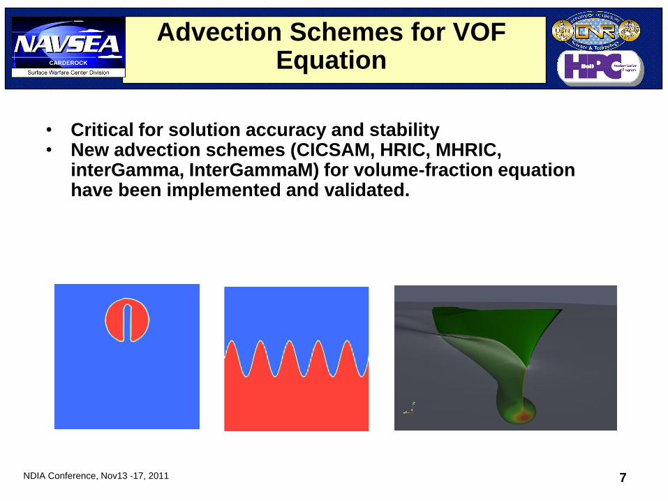
Advection Schemes for VOF Equation
• Critical for solution accuracy and stability • New advection schemes (CICSAM, HRIC, MHRIC,
interGamma, InterGammaM) for volume-fraction equation have been implemented and validated.
5-Dec-11 7
NDIA Conference, Nov13 -17, 2011 8
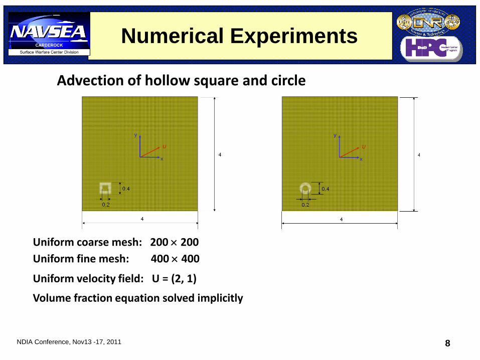
Advection of hollow square and circle
Uniform coarse mesh: 200 200
Uniform fine mesh: 400 400
Uniform velocity field: U = (2, 1)
Volume fraction equation solved implicitly
Numerical Experiments
NDIA Conference, Nov13 -17, 2011 9
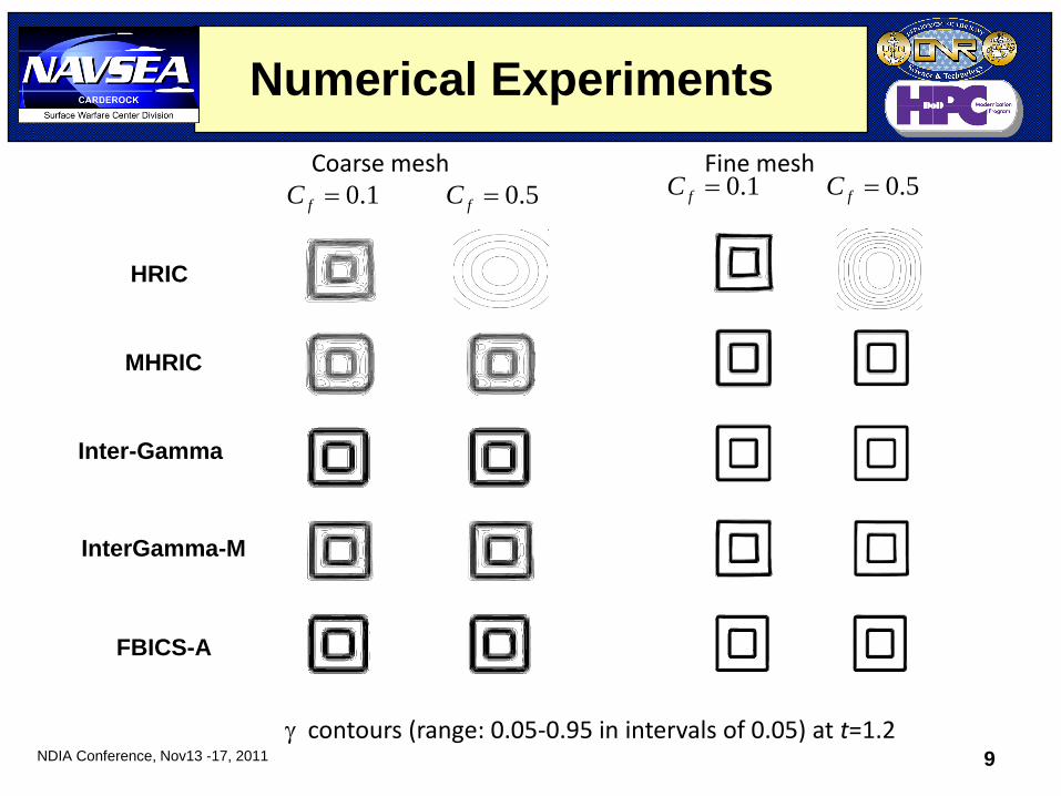
Numerical Experiments
1.0fC 5.0fC 1.0fC 5.0fC
contours (range: 0.05-0.95 in intervals of 0.05) at t=1.2
Coarse mesh Fine mesh
HRIC
MHRIC
Inter-Gamma
InterGamma-M
FBICS-A
NDIA Conference, Nov13 -17, 2011 10
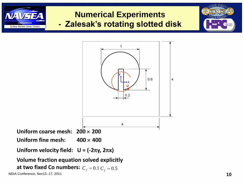
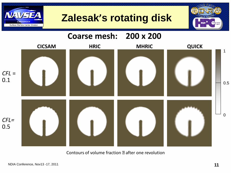
Numerical Experiments - Zalesak’s rotating slotted disk
Uniform coarse mesh: 200 200
Uniform fine mesh: 400 400
Uniform velocity field: U = (-2y, 2x)
Volume fraction equation solved explicitly at two fixed Co numbers: 1.0fC 5.0fC
NDIA Conference, Nov13 -17, 2011 11
Zalesak’s rotating disk
1 0.5 0
Contours of volume fraction after one revolution
CFL = 0.1
CFL= 0.5
CICSAM HRIC MHRIC QUICK
Coarse mesh: 200 x 200
5-Dec-11 11
NDIA Conference, Nov13 -17, 2011 12
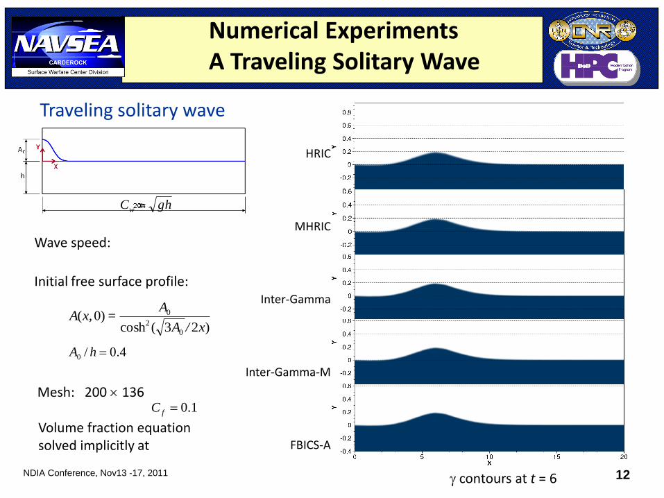
Numerical Experiments A Traveling Solitary Wave
Traveling solitary wave
HRIC
MHRIC
Inter-Gamma
Inter-Gamma-M
FBICS-A
contours at t = 6
ghCw
Wave speed:
Initial free surface profile:
)23(cosh)0(
0
2
0
x/A
A=x,A
Mesh: 200 136
4.0/0 hA
Volume fraction equation solved implicitly at
1.0fC
NDIA Conference, Nov13 -17, 2011 13
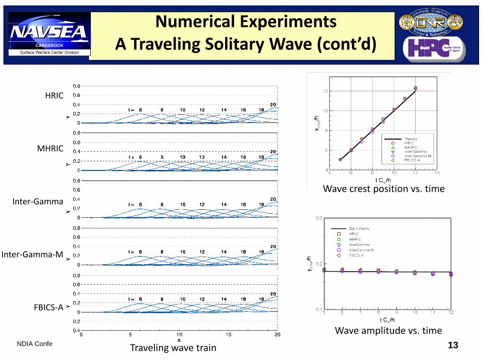
Numerical Experiments A Traveling Solitary Wave (cont’d)
HRIC
MHRIC
Inter-Gamma
Inter-Gamma-M
FBICS-A
Traveling wave train
Wave crest position vs. time
Wave amplitude vs. time
NDIA Conference, Nov13 -17, 2011 14
• An international workshop series started in 1990 to evaluate the state of the art in CFD for ship hydrodynamics
• Held in Gothenburg, Sweden in December 2010.
• For G2.01K, three ships have been selected for test case – KVLCC2 (tanker)
– DTMB 5415 (destroyer)
– KCS (container ship)
• A total of 82 entries from roughly 40 organizations worldwide – the largest ever
• Our entries with NavyFoam – KVLCC2 (case 1.1 – double-body)
– DTMB 5415 (cases – 3.1a, 3.1b, 3-5, fixed and free sinkage and trim)
Gothenburg 2010 Workshop
NDIA Conference, Nov13 -17, 2011 15
• Three hull forms
– U.S. Navy Combatant DTMB 5415
– The Korean VLCC KVLCC2
– The Korean container ship KCS
• Types of test cases – Local flow at fixed sinkage and trim
– Local flow at dynamic sinkage and trim
Gothenburg 2010 Workshop
NDIA Conference, Nov13 -17, 2011 16
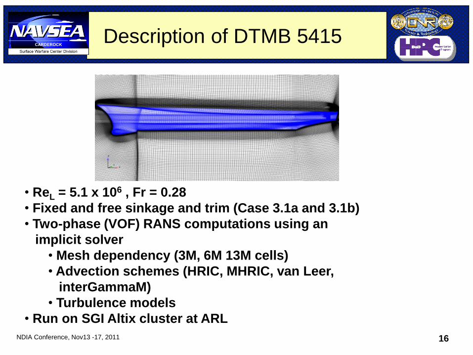
Description of DTMB 5415
• ReL = 5.1 x 10⁶ , Fr = 0.28
• Fixed and free sinkage and trim (Case 3.1a and 3.1b)
• Two-phase (VOF) RANS computations using an
implicit solver
• Mesh dependency (3M, 6M 13M cells)
• Advection schemes (HRIC, MHRIC, van Leer,
interGammaM)
• Turbulence models
• Run on SGI Altix cluster at ARL
NDIA Conference, Nov13 -17, 2011 17
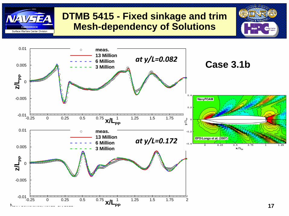
DTMB 5415 - Fixed sinkage and trim Mesh-dependency of Solutions
x/LPP
z/L
PP
-0.25 0 0.25 0.5 0.75 1 1.25 1.5 1.75 2-0.01
-0.005
0
0.005
0.01 meas.
13 Million
6 Million
3 Million
x/LPP
z/L
PP
-0.25 0 0.25 0.5 0.75 1 1.25 1.5 1.75 2-0.01
-0.005
0
0.005
0.01 meas.
13 Million
6 Million
3 Million
at y/L=0.082
at y/L=0.172
Case 3.1b
NDIA Conference, Nov13 -17, 2011 18
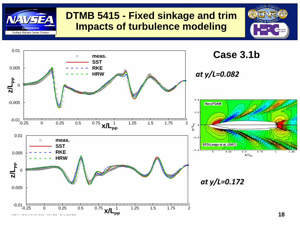
DTMB 5415 - Fixed sinkage and trim Impacts of turbulence modeling
at y/L=0.082
at y/L=0.172
x/LPP
z/L
PP
-0.25 0 0.25 0.5 0.75 1 1.25 1.5 1.75 2-0.01
-0.005
0
0.005
0.01
meas.
SST
RKE
HRW
x/LPP
z/L
PP
-0.25 0 0.25 0.5 0.75 1 1.25 1.5 1.75 2-0.01
-0.005
0
0.005
0.01meas.
SST
RKE
HRW
Case 3.1b
NDIA Conference, Nov13 -17, 2011 19
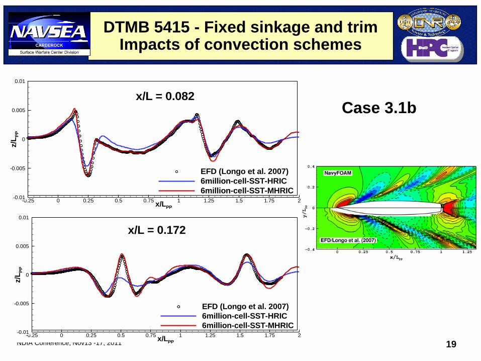
DTMB 5415 - Fixed sinkage and trim Impacts of convection schemes
x/LPP
z/L
PP
-0.25 0 0.25 0.5 0.75 1 1.25 1.5 1.75 2-0.01
-0.005
0
0.005
0.01
EFD (Longo et al. 2007)
6million-cell-SST-HRIC
6million-cell-SST-MHRIC
x/L = 0.082
x/LPP
z/L
PP
-0.25 0 0.25 0.5 0.75 1 1.25 1.5 1.75 2-0.01
-0.005
0
0.005
0.01
EFD (Longo et al. 2007)
6million-cell-SST-HRIC
6million-cell-SST-MHRIC
x/L = 0.172
Case 3.1b
NDIA Conference, Nov13 -17, 2011 20
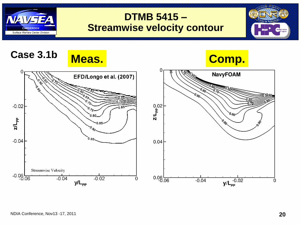
DTMB 5415 – Streamwise velocity contour
Meas. Comp. Case 3.1b
NDIA Conference, Nov13 -17, 2011 21
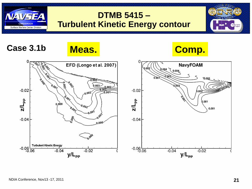
DTMB 5415 – Turbulent Kinetic Energy contour
Meas. Comp. Case 3.1b
NDIA Conference, Nov13 -17, 2011 22
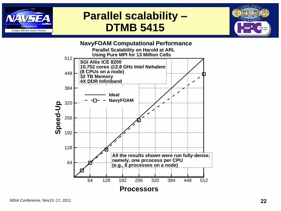
Parallel scalability – DTMB 5415
Processors
Sp
ee
d-U
p
64 128 192 256 320 384 448 512
64
128
192
256
320
384
448
512
Ideal
NavyFOAM
NavyFOAM Computational PerformanceParallel Scalability on Harold at ARLUsing Pure MPI for 13 Million Cells
SGI Altix ICE 820010,752 cores @2.8 GHz Intel Nehalem(8 CPUs on a node)32 TB Memory4X DDR Infiniband
All the results shown were run fully-dense;namely, one prcocess per CPU(e.g., 8 processes on a node)
NDIA Conference, Nov13 -17, 2011 23
DTMB 5415 – Fixed sinkage and trim
Case 3.1a -
Calm water conditions
Fixed sinkage: -1.82x10⁻³, trim: -0.108o
ReL = 1.19x10⁷, Fr = 0.28
NDIA Conference, Nov13 -17, 2011 24
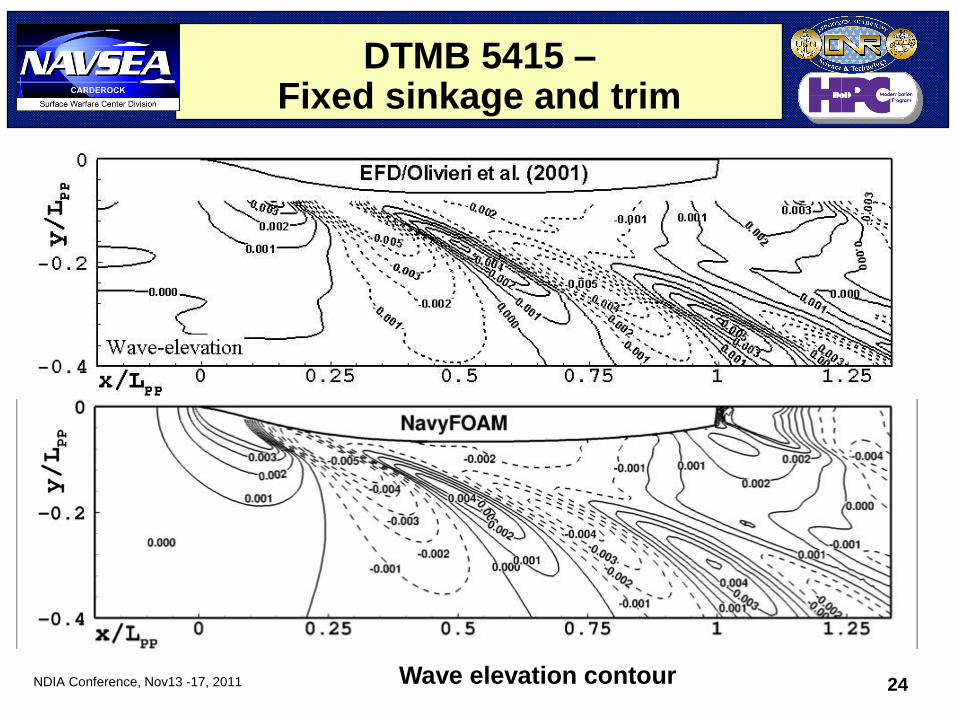
DTMB 5415 – Fixed sinkage and trim
Wave elevation contour
NDIA Conference, Nov13 -17, 2011 25
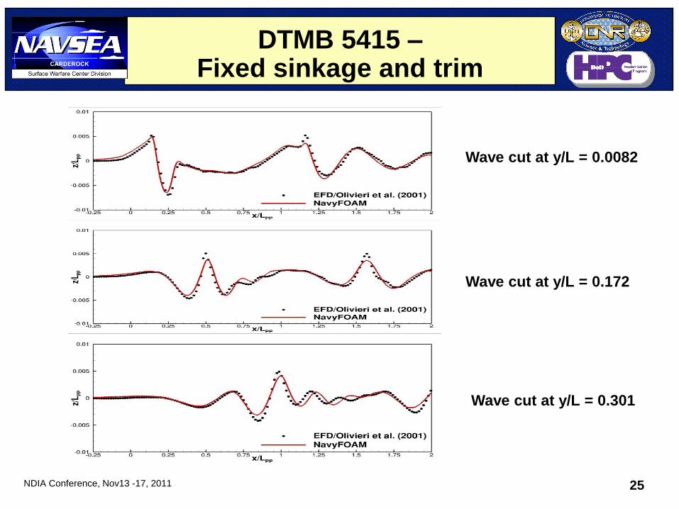
DTMB 5415 – Fixed sinkage and trim
Wave cut at y/L = 0.0082
Wave cut at y/L = 0.172
Wave cut at y/L = 0.301
NDIA Conference, Nov13 -17, 2011 26
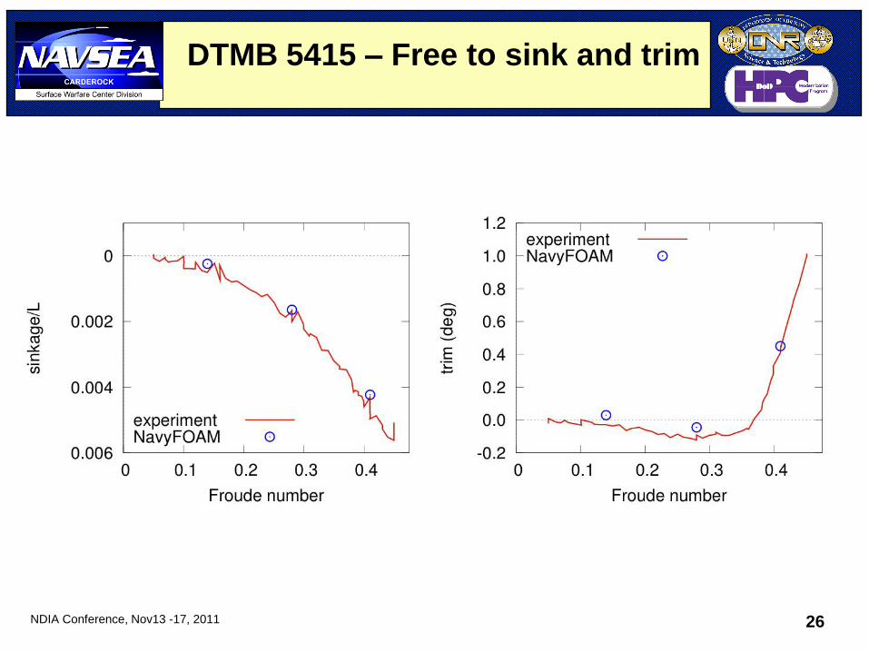
DTMB 5415 – Free to sink and trim
NDIA Conference, Nov13 -17, 2011 27
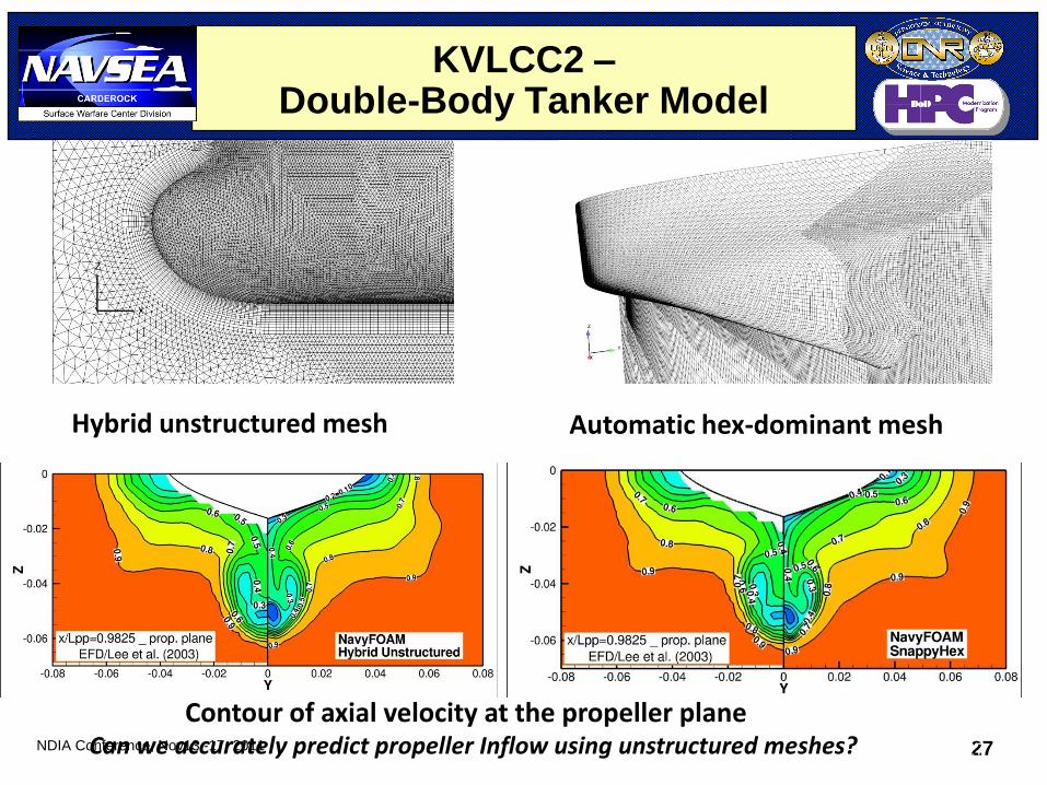
KVLCC2 – Double-Body Tanker Model
27
Hybrid unstructured mesh Automatic hex-dominant mesh
Contour of axial velocity at the propeller plane Can we accurately predict propeller Inflow using unstructured meshes?
NDIA Conference, Nov13 -17, 2011 28
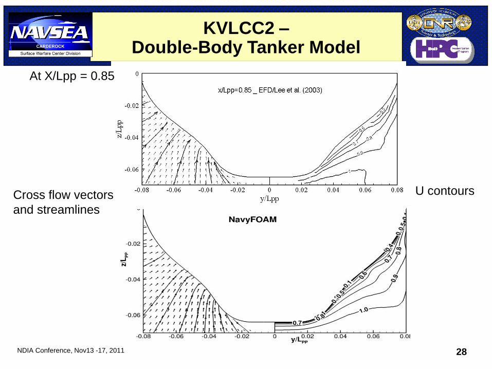
U contours Cross flow vectors
and streamlines
At X/Lpp = 0.85
KVLCC2 – Double-Body Tanker Model
NDIA Conference, Nov13 -17, 2011 29
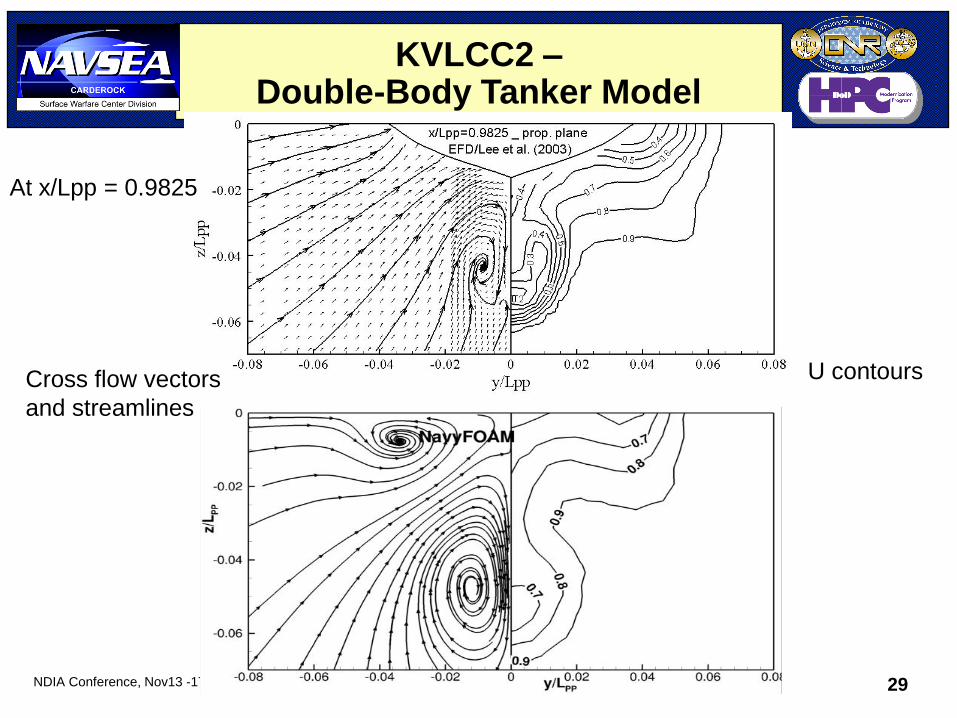
At x/Lpp = 0.9825
Cross flow vectors
and streamlines
U contours
KVLCC2 – Double-Body Tanker Model
NDIA Conference, Nov13 -17, 2011 30
• Background
• Overview of NavyFOAM
• Validations
– Canonical problems
– Gothenburg 2010 workshop
• Applications
– JHSS
– DDG-1000
• Conclusions
Outline
NDIA Conference, Nov13 -17, 2011 31
JHSS –
Description of experiment
• Joint High Speed Sealift (JHSS) is a naval concept vehicle with axial-flow waterjets.
• Detailed flow measurements were conducted in the towing basins at NSWCCD (Jessup et al., 2008).
• The model configurations were tested: – Bare hull with four propellers and strut appendages
– Bare hull with axial-flow waterjets
– Bare hull with mixed-flow waterjets
• Three hull variants were designed with a gooseneck bow and different transoms
NDIA Conference, Nov13 -17, 2011 32
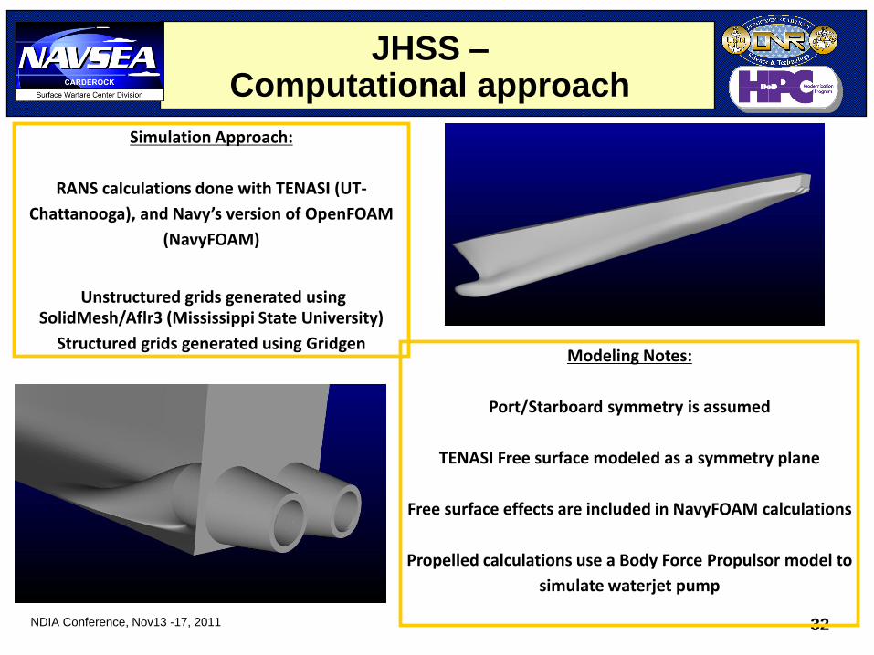
Simulation Approach:
RANS calculations done with TENASI (UT-
Chattanooga), and Navy’s version of OpenFOAM
(NavyFOAM)
Unstructured grids generated using SolidMesh/Aflr3 (Mississippi State University)
Structured grids generated using Gridgen Modeling Notes:
Port/Starboard symmetry is assumed
TENASI Free surface modeled as a symmetry plane
Free surface effects are included in NavyFOAM calculations
Propelled calculations use a Body Force Propulsor model to
simulate waterjet pump
JHSS – Computational approach
NDIA Conference, Nov13 -17, 2011 33
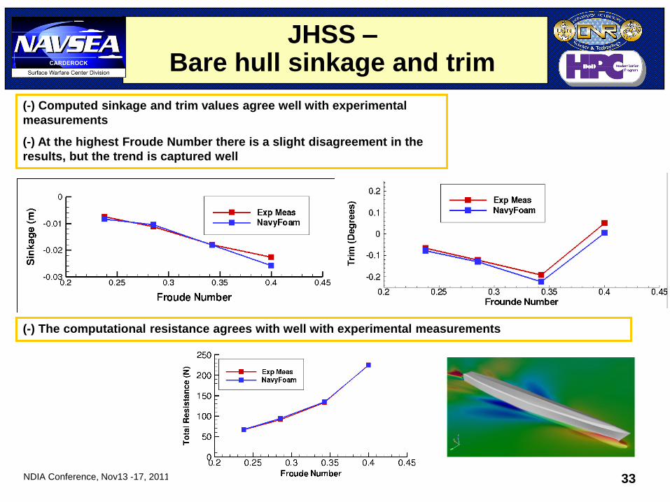
(-) The computational resistance agrees with well with experimental measurements
(-) Computed sinkage and trim values agree well with experimental
measurements
(-) At the highest Froude Number there is a slight disagreement in the
results, but the trend is captured well
JHSS – Bare hull sinkage and trim
NDIA Conference, Nov13 -17, 2011 34
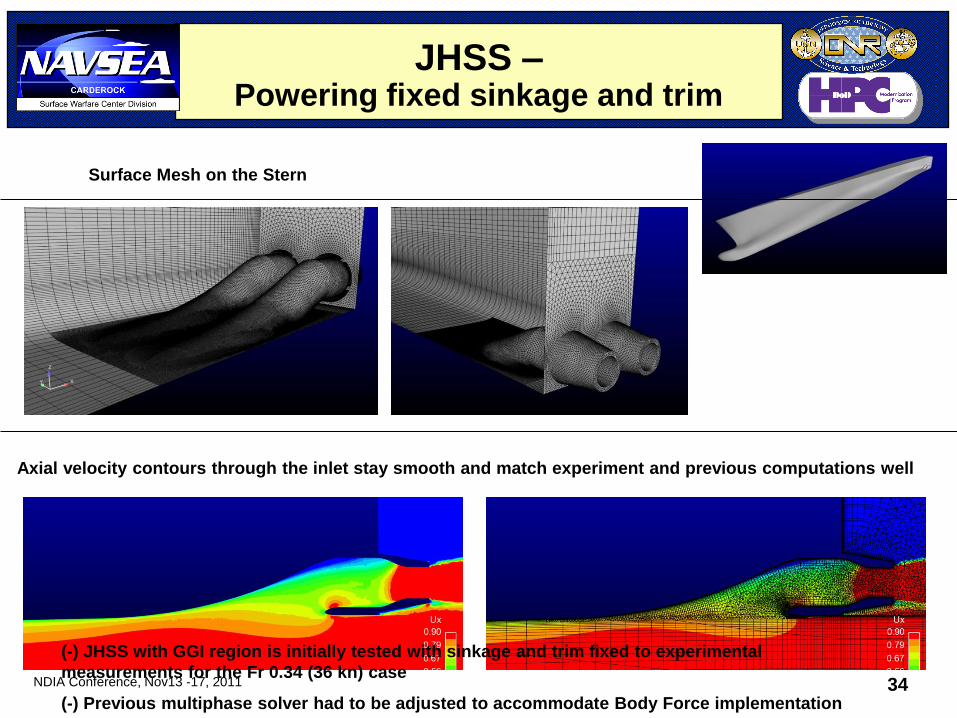
(-) JHSS with GGI region is initially tested with sinkage and trim fixed to experimental
measurements for the Fr 0.34 (36 kn) case
(-) Previous multiphase solver had to be adjusted to accommodate Body Force implementation
Surface Mesh on the Stern
Axial velocity contours through the inlet stay smooth and match experiment and previous computations well
JHSS – Powering fixed sinkage and trim
NDIA Conference, Nov13 -17, 2011 35
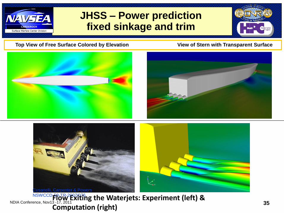
Cusanelli, Carpenter & Powers
NSWCCD-50-TR-2007/076
Top View of Free Surface Colored by Elevation View of Stern with Transparent Surface
Flow Exiting the Waterjets: Experiment (left) & Computation (right)
JHSS – Power prediction fixed sinkage and trim
NDIA Conference, Nov13 -17, 2011 36
Fully Appended DDG-1000
• Fully appended configuration includes bilge keels, skeg, shafts, struts, and rudders.
• Forces and moments from RANS simulations were used to provide hydrodynamic coefficients for TEMPEST.
• RANS run matrix: – Straight ahead case: different speeds with various drift angles
– Constant turning case: turning radius = 3*body length (L), 4L, 5L, 10L
• Grids used: unstructured 18 million cells including prism layers and tetrahedra.
NDIA Conference, Nov13 -17, 2011 37
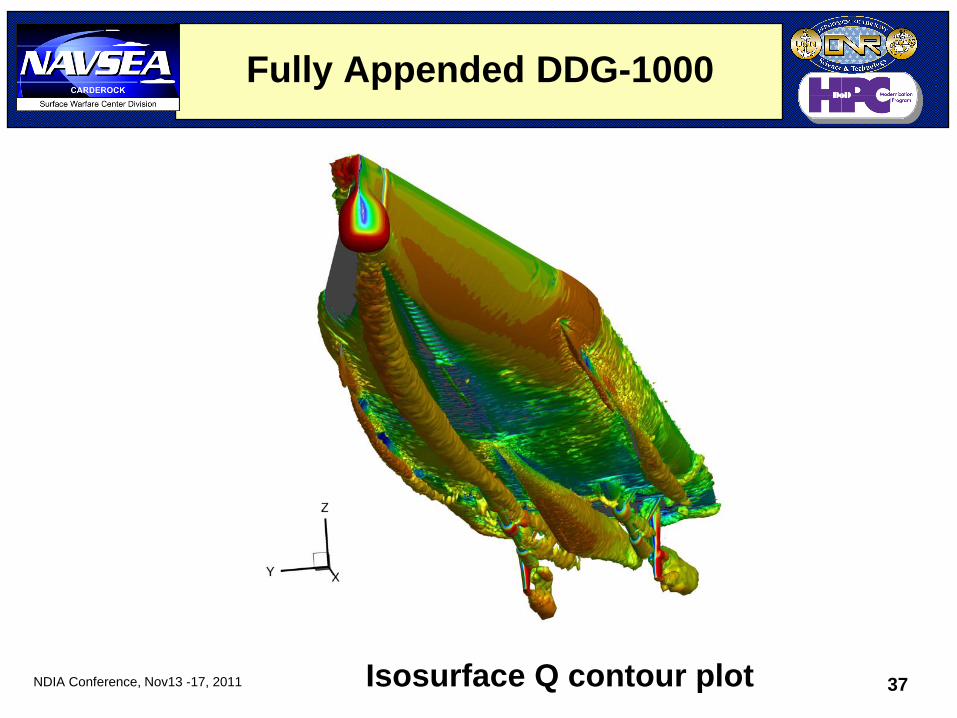
Fully Appended DDG-1000
Isosurface Q contour plot
NDIA Conference, Nov13 -17, 2011 38
Summary & Conclusions
• Surface ship applications involve complex flow physics such as turbulence, two-phase flow phenomena near the air-water interface, 6-DOF motion, and environments.
• NavyFOAM has been validated for free-surface problems ranging from canonical problems to model ships.
• NavyFOAM was among the best performing RANS solvers to accurately predict resistance, wave profiles, and local flow at Gothenburg 2010 Workshop.
• We’ve also developed best practices in numerical algorithms, discretization schemes, and turbulence modeling for surface ship applications. – Fully implicit solution algorithm
– RANS turbulence modeling
– Advection schemes for VOF equation


![Lecture [3] : Surface Modeling€¦ · Lecture [3] : Surface Modeling. Surface model ... Therefore, this type of surface representation is called nonparametric representation. The](https://static.fdocuments.in/doc/165x107/5eb5ad6f8eb1025587244fa4/lecture-3-surface-modeling-lecture-3-surface-modeling-surface-model-.jpg)