Physics 862 Accelerator System Introduction to RF and ...ostroumo/MSU/Lectures...o Linear-beam tubes...
58
Physics 862 Accelerator System Introduction to RF and Microwave Alireza Nassiri Adjunct Professor of ECE
Transcript of Physics 862 Accelerator System Introduction to RF and ...ostroumo/MSU/Lectures...o Linear-beam tubes...
Physics 862
Accelerator System
Introduction to RF and Microwave
Alireza Nassiri
Adjunct Professor of ECE

Outline
• Three lectures:
• Lecture 1 – today
o Introduction
o Overview of RF power generation
• Lecture 2 – Wednesday, November 7
o Power transport – part one
• Lecture 3 – Wednesday, November 7
o Power transport – part two
o Introduction to low-level rf and controls
• Homework
A. Nassiri PHY 862 Accelerator Systems 2
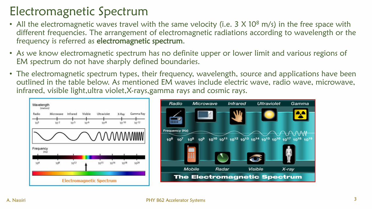
Electromagnetic Spectrum
• All the electromagnetic waves travel with the same velocity (i.e. 3 X 10⁸
m/s) in the free space with
different frequencies. The arrangement of electromagnetic radiations according to wavelength or the
frequency is referred as electromagnetic spectrum.
• As we know electromagnetic spectrum has no definite upper or lower limit and various regions of
EM spectrum do not have sharply defined boundaries.
• The electromagnetic spectrum types, their frequency, wavelength, source and applications have been
outlined in the table below. As mentioned EM waves include electric wave, radio wave, microwave,
infrared, visible light,ultra violet,X-rays,gamma rays and cosmic rays.
A. Nassiri PHY 862 Accelerator Systems 3
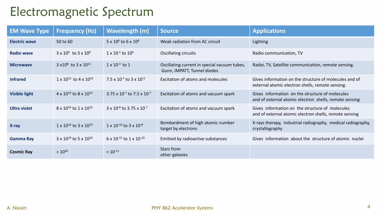
Electromagnetic Spectrum
EM Wave Type Frequency (Hz) Wavelength (m) Source Applications
Electric wave 50 to 60 5 x 10⁶ to 6 x 10⁶ Weak radiation from AC circuit Lighting
Radio wave 3 x 10⁴ to 3 x 10⁹ 1 x 10⁻¹ to 104 Oscillating circuits Radio communication, TV
Microwave 3 x10⁸ to 3 x 10¹¹ 1 x 10⁻³ to 1 Oscillating current in special vacuum tubes,Gunn, IMPATT, Tunnel diodes
Radar, TV, Satellite communication, remote sensing.
Infrared 1 x 10¹³ to 4 x 10¹⁴ 7.5 x 10⁻⁷ to 3 x 10⁻⁵ Excitation of atoms and molecules Gives information on the structure of molecules and of external atomic electron shells, remote sensing.
Visible light 4 x 10¹⁴ to 8 x 10¹⁴ 3.75 x 10⁻⁷ to 7.5 x 10⁻⁷ Excitation of atoms and vacuum spark Gives information on the structure of molecules and of external atomic electron shells, remote sensing
Ultra violet 8 x 10¹⁴ to 1 x 10¹⁶ 3 x 10⁻⁸ to 3.75 x 10⁻⁷ Excitation of atoms and vacuum spark Gives information on the structure of molecules and of external atomic electron shells, remote sensing
X-ray 1 x 10¹⁶ to 3 x 10¹⁹ 1 x 10⁻¹⁰ to 3 x 10⁻⁸ Bombardment of high atomic number target by electrons
X-rays therapy, industrial radiography, medical radiography,crystallography
Gamma Ray 3 x 10¹⁹ to 5 x 10²⁰ 6 x 10-15 to 1 x 10⁻¹⁰ Emitted by radioactive substances Gives information about the structure of atomic nuclei
Cosmic Ray > 1020 < 10-11 Stars from other galaxies
A. Nassiri PHY 862 Accelerator Systems 4
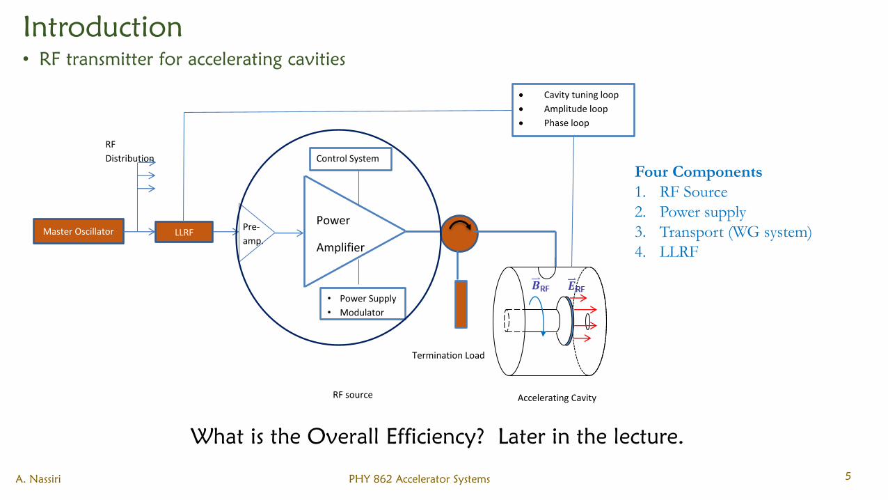
Introduction
• RF transmitter for accelerating cavities
Master Oscillator LLRF
RF
Distribution
Pre-
amp.
Power
Amplifier
Control System
• Power Supply
• Modulator
Cavity tuning loop
Amplitude loop
Phase loop
Termination Load
Accelerating CavityRF source
A. Nassiri PHY 862 Accelerator Systems 5
Four Components
1. RF Source
2. Power supply
3. Transport (WG system)
4. LLRF
What is the Overall Efficiency? Later in the lecture.
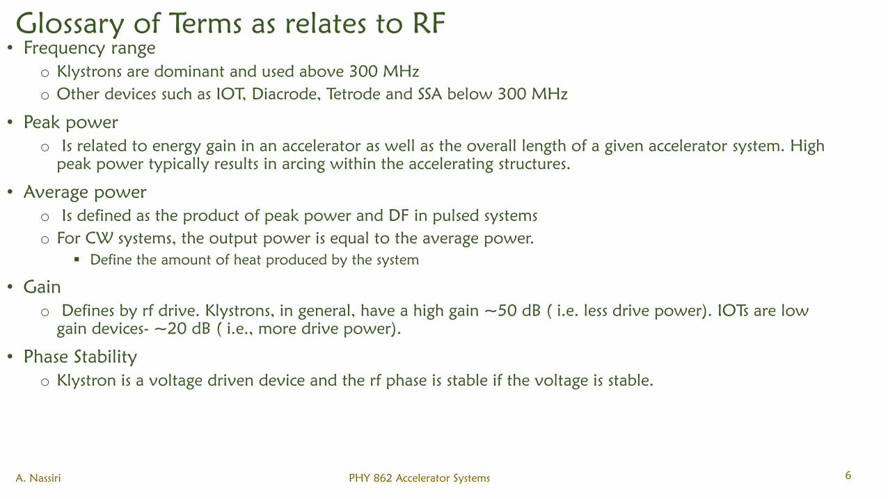
Glossary of Terms as relates to RF
• Frequency range
o Klystrons are dominant and used above 300 MHz
o Other devices such as IOT, Diacrode, Tetrode and SSA below 300 MHz
• Peak power
o Is related to energy gain in an accelerator as well as the overall length of a given accelerator system. High
peak power typically results in arcing within the accelerating structures.
• Average power
o Is defined as the product of peak power and DF in pulsed systems
o For CW systems, the output power is equal to the average power.
Define the amount of heat produced by the system
• Gain
o Defines by rf drive. Klystrons, in general, have a high gain ~50 dB ( i.e. less drive power). IOTs are low
gain devices- ~20 dB ( i.e., more drive power).
• Phase Stability
o Klystron is a voltage driven device and the rf phase is stable if the voltage is stable.
A. Nassiri PHY 862 Accelerator Systems 6
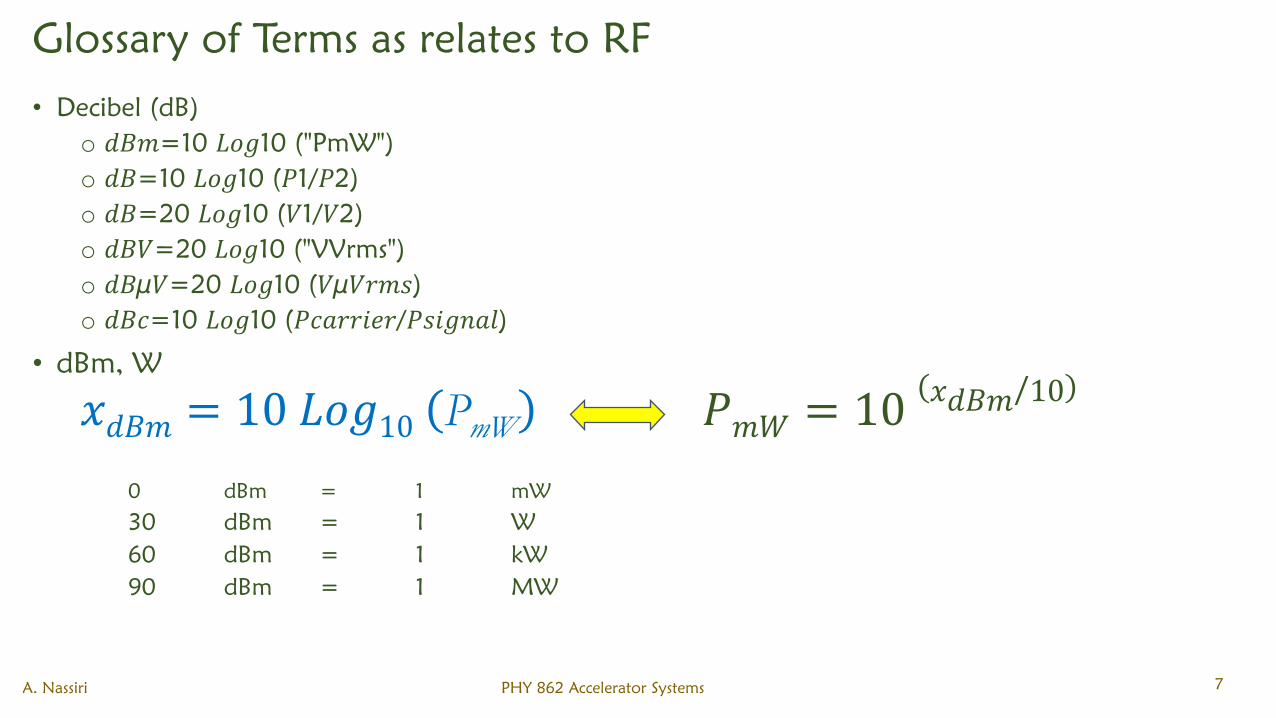
Glossary of Terms as relates to RF
• Decibel (dB)
o 𝑑𝐵𝑚=10 𝐿𝑜𝑔10 ("PmW")
o 𝑑𝐵=10 𝐿𝑜𝑔10 (𝑃1/𝑃2)
o 𝑑𝐵=20 𝐿𝑜𝑔10 (𝑉1/𝑉2)
o 𝑑𝐵𝑉=20 𝐿𝑜𝑔10 ("VVrms")
o 𝑑𝐵µ𝑉=20 𝐿𝑜𝑔10 (𝑉µ𝑉𝑟𝑚𝑠)
o 𝑑𝐵𝑐=10 𝐿𝑜𝑔10 (𝑃𝑐𝑎𝑟𝑟𝑖𝑒𝑟/𝑃𝑠𝑖𝑔𝑛𝑎𝑙)
• dBm, W
𝑥𝑑𝐵𝑚 = 10 𝐿𝑜𝑔10 PmW 𝑃𝑚𝑊 = 10(𝑥𝑑𝐵𝑚/10)
0 dBm = 1 mW
30 dBm = 1 W
60 dBm = 1 kW
90 dBm = 1 MW
A. Nassiri PHY 862 Accelerator Systems 7
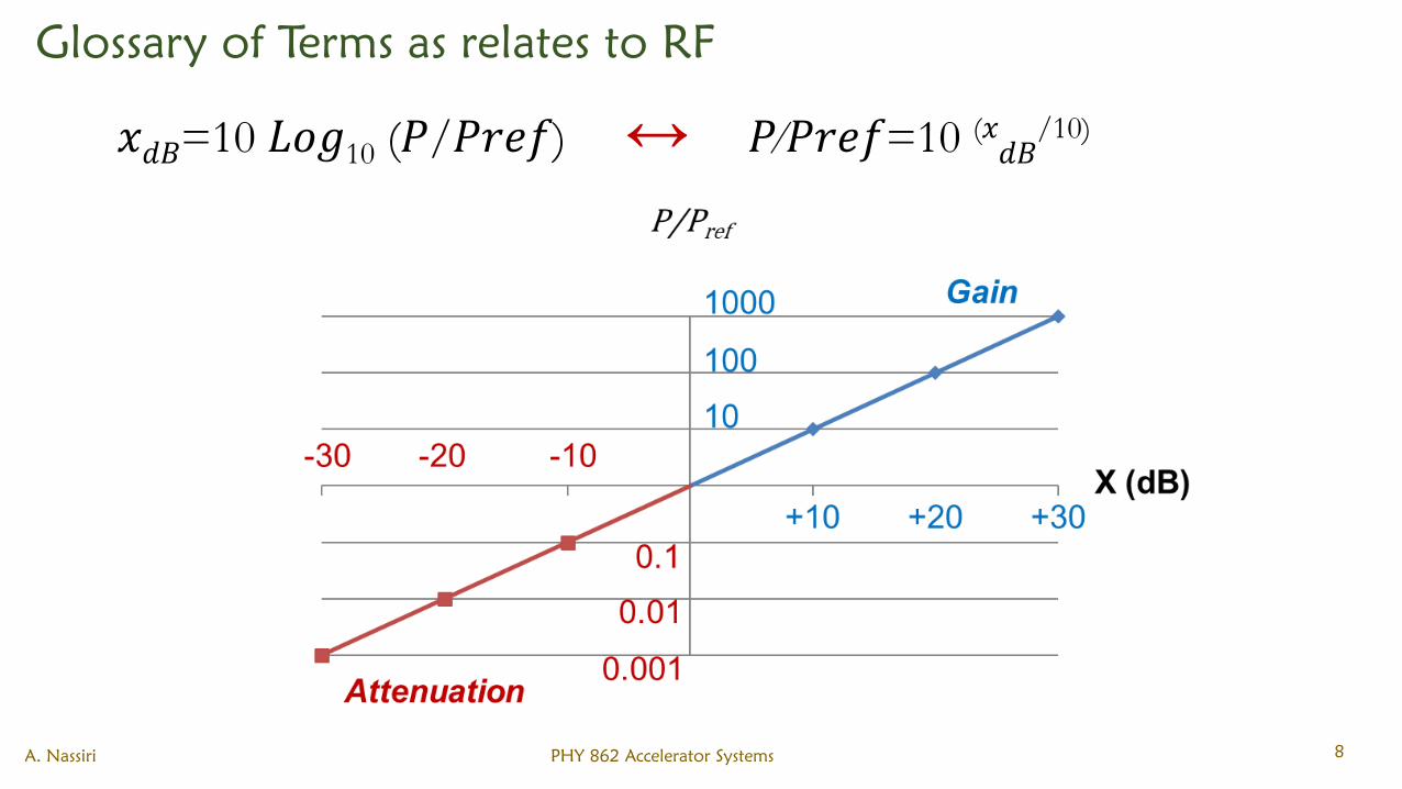
Glossary of Terms as relates to RF
A. Nassiri PHY 862 Accelerator Systems 8
𝑥𝑑𝐵=10 𝐿𝑜𝑔10 (𝑃/𝑃𝑟𝑒𝑓) ↔ 𝑃∕𝑃𝑟𝑒𝑓=10 (𝑥𝑑𝐵/10)
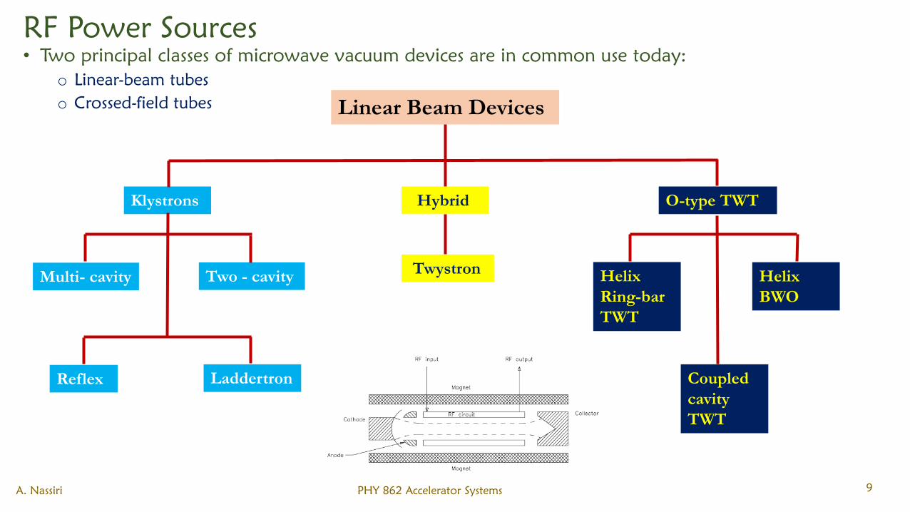
RF Power Sources
• Two principal classes of microwave vacuum devices are in common use today:
o Linear-beam tubes
o Crossed-field tubes
A. Nassiri PHY 862 Accelerator Systems 9
Linear Beam Devices
Klystrons Hybrid O-type TWT
Twystron Two - cavityMulti- cavity
Reflex Laddertron
Helix
Ring-bar
TWT
Helix
BWO
Coupled
cavity
TWT
Linear Beam Devices
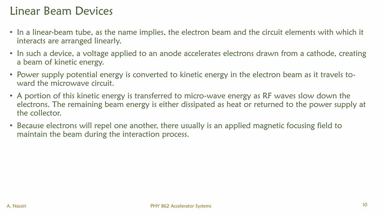
• In a linear-beam tube, as the name implies, the electron beam and the circuit elements with which it
interacts are arranged linearly.
• In such a device, a voltage applied to an anode accelerates electrons drawn from a cathode, creating
a beam of kinetic energy.
• Power supply potential energy is converted to kinetic energy in the electron beam as it travels to-
ward the microwave circuit.
• A portion of this kinetic energy is transferred to micro-wave energy as RF waves slow down the
electrons. The remaining beam energy is either dissipated as heat or returned to the power supply at
the collector.
• Because electrons will repel one another, there usually is an applied magnetic focusing field to
maintain the beam during the interaction process.
A. Nassiri PHY 862 Accelerator Systems 10
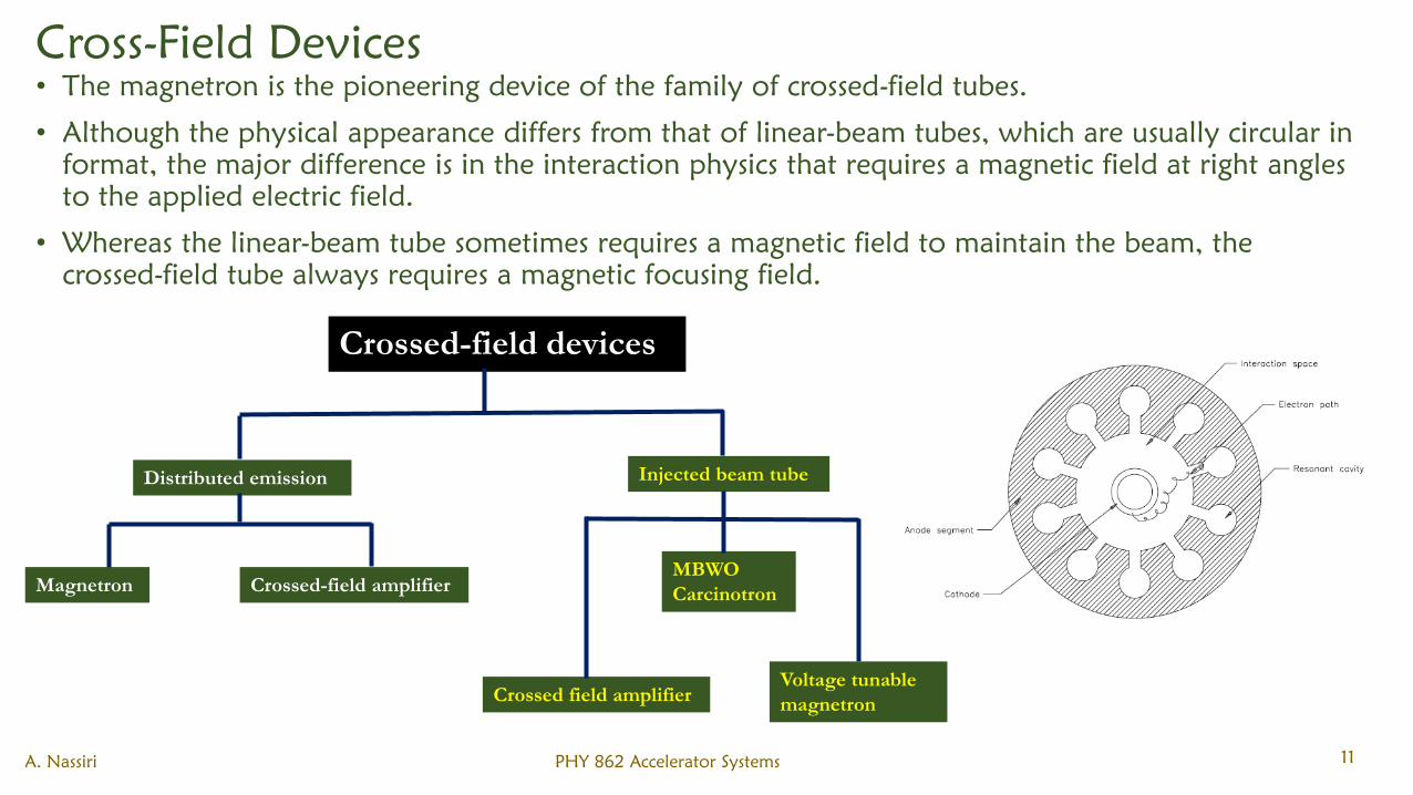
Cross-Field Devices
• The magnetron is the pioneering device of the family of crossed-field tubes.
• Although the physical appearance differs from that of linear-beam tubes, which are usually circular in
format, the major difference is in the interaction physics that requires a magnetic field at right angles
to the applied electric field.
• Whereas the linear-beam tube sometimes requires a magnetic field to maintain the beam, the
crossed-field tube always requires a magnetic focusing field.
A. Nassiri PHY 862 Accelerator Systems 11
Crossed-field devices
Distributed emission Injected beam tube
Crossed-field amplifierMagnetron
Crossed field amplifier
MBWO
Carcinotron
Voltage tunable
magnetron
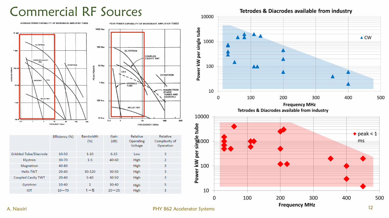
Commercial RF Sources
A. Nassiri PHY 862 Accelerator Systems 12
10
100
1000
10000
0 100 200 300 400 500P
ow
er
kW p
er
sin
gle
tu
be
Frequency MHz
Tetrodes & Diacrodes available from industry
peak < 1ms
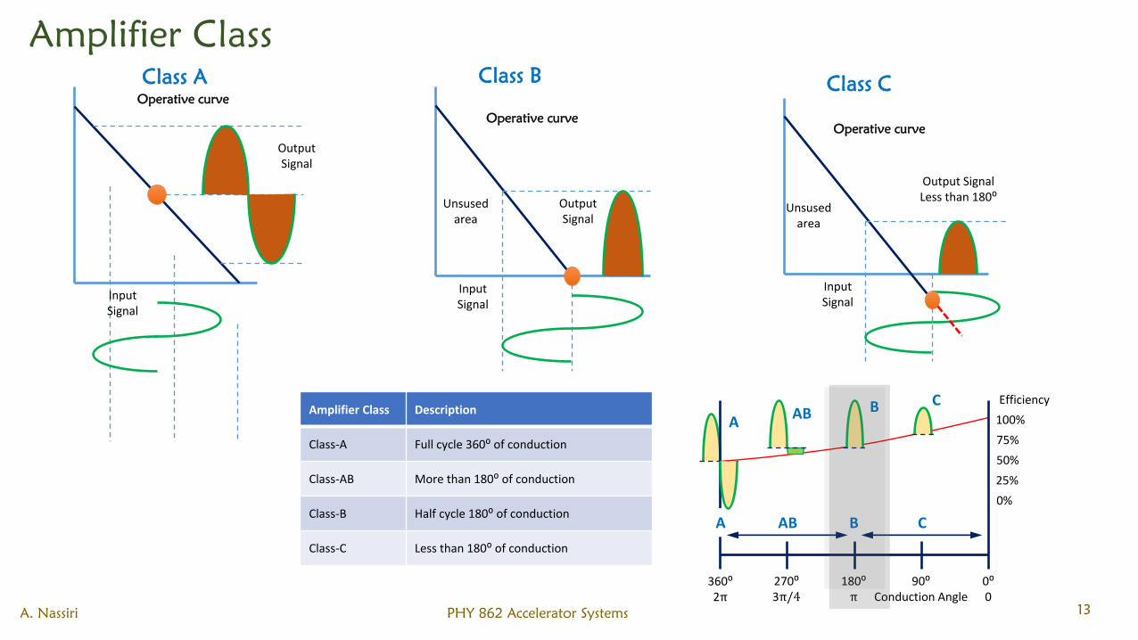
Amplifier Class
A. Nassiri PHY 862 Accelerator Systems 13
InputSignal
OutputSignal
Operative curve
InputSignal
OutputSignal
Operative curve
Unsusedarea
InputSignal
Output SignalLess than 180⁰
Operative curve
Unsusedarea
CBABA
360⁰2π
270⁰3π/4
180⁰π
90⁰Conduction Angle
0⁰0
A AB B C
0%
25%
50%
75%
100%
EfficiencyAmplifier Class Description
Class-A Full cycle 360⁰ of conduction
Class-AB More than 180⁰ of conduction
Class-B Half cycle 180⁰ of conduction
Class-C Less than 180⁰ of conduction
Class BClass AClass C
Grid Vacuum Tubes
• The physical construction of a vacuum tube causes the output power and available gain to decrease
with increasing frequency. The principal limitations faced by grid-based devices include the
following:
o Physical size. Ideally, the RF voltages between electrodes should be uniform, but this condition cannot be
realized unless the major electrode dimensions are significantly less than 1/4 wavelength at the operating
frequency. This restriction presents no problems at VHF, but as the operating frequency increases into the
microwave range, severe restrictions are placed on the physical size of individual tube elements.
o Electron transit time. Inter electrode spacing, principally between the grid and the cathode, must be scaled
inversely with frequency to avoid problems associated with electron transit time. Possible adverse
conditions include: 1) excessive loading of the drive source, 2) reduction in power gain, 3) back-heating of
the cathode as a result of electron bombardment, and 4) reduced conversion efficiency.
o Voltage standoff. High-power tubes operate at high voltages. This presents significant problems for
microwave vacuum tubes. For example, at 1 GHz the grid-cathode spacing must not exceed a few mils. This
places restrictions on the operating voltages that may be applied to the individual elements.
o Circulating currents. Substantial RF currents may develop as a result of the inherent inter electrode
capacitances and stray inductances/capacitances of the device. Significant heating of the grid, connecting
leads, and vacuum seals may result.
o Heat dissipation. Because the elements of a microwave grid tube must be kept small, power dissipation is
limited.
A. Nassiri PHY 862 Accelerator Systems 14
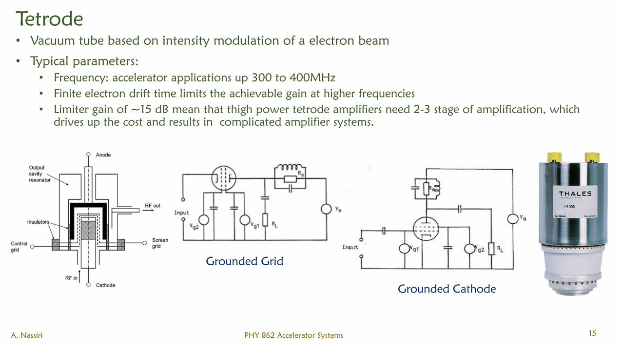
Tetrode
• Vacuum tube based on intensity modulation of a electron beam
• Typical parameters:
• Frequency: accelerator applications up 300 to 400MHz
• Finite electron drift time limits the achievable gain at higher frequencies
• Limiter gain of ~15 dB mean that thigh power tetrode amplifiers need 2-3 stage of amplification, which
drives up the cost and results in complicated amplifier systems.
A. Nassiri PHY 862 Accelerator Systems 15
Grounded Grid
Grounded Cathode
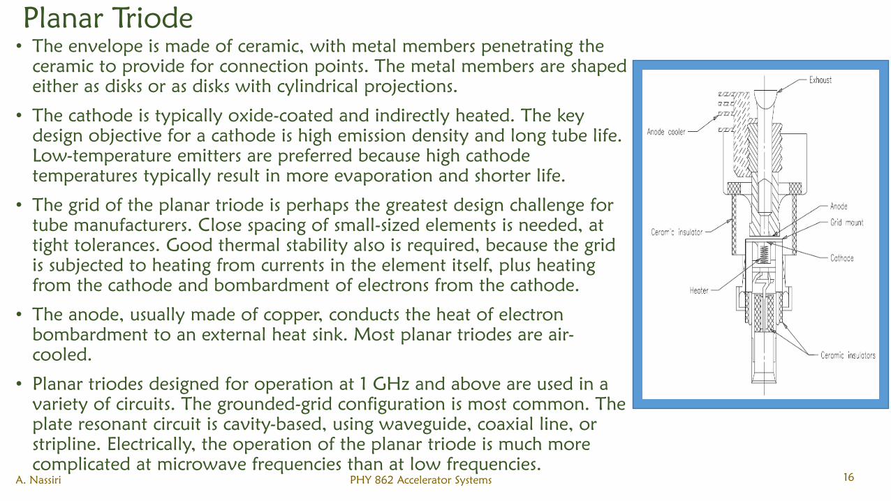
Planar Triode
• The envelope is made of ceramic, with metal members penetrating the
ceramic to provide for connection points. The metal members are shaped
either as disks or as disks with cylindrical projections.
• The cathode is typically oxide-coated and indirectly heated. The key
design objective for a cathode is high emission density and long tube life.
Low-temperature emitters are preferred because high cathode
temperatures typically result in more evaporation and shorter life.
• The grid of the planar triode is perhaps the greatest design challenge for
tube manufacturers. Close spacing of small-sized elements is needed, at
tight tolerances. Good thermal stability also is required, because the grid
is subjected to heating from currents in the element itself, plus heating
from the cathode and bombardment of electrons from the cathode.
• The anode, usually made of copper, conducts the heat of electron
bombardment to an external heat sink. Most planar triodes are air-
cooled.
• Planar triodes designed for operation at 1 GHz and above are used in a
variety of circuits. The grounded-grid configuration is most common. The
plate resonant circuit is cavity-based, using waveguide, coaxial line, or
stripline. Electrically, the operation of the planar triode is much more
complicated at microwave frequencies than at low frequencies.
A. Nassiri PHY 862 Accelerator Systems 16
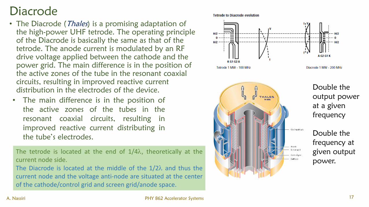
Diacrode
• The Diacrode (Thales) is a promising adaptation of
the high-power UHF tetrode. The operating principle
of the Diacrode is basically the same as that of the
tetrode. The anode current is modulated by an RF
drive voltage applied between the cathode and the
power grid. The main difference is in the position of
the active zones of the tube in the resonant coaxial
circuits, resulting in improved reactive current
distribution in the electrodes of the device.
A. Nassiri PHY 862 Accelerator Systems 17
The tetrode is located at the end of 1/4, theoretically at thecurrent node side.The Diacrode is located at the middle of the 1/2 and thus thecurrent node and the voltage anti-node are situated at the centerof the cathode/control grid and screen grid/anode space.
• The main difference is in the position of
the active zones of the tubes in the
resonant coaxial circuits, resulting in
improved reactive current distributing in
the tube’s electrodes.
Double the
output power
at a given
frequency
Double the
frequency at
given output
power.
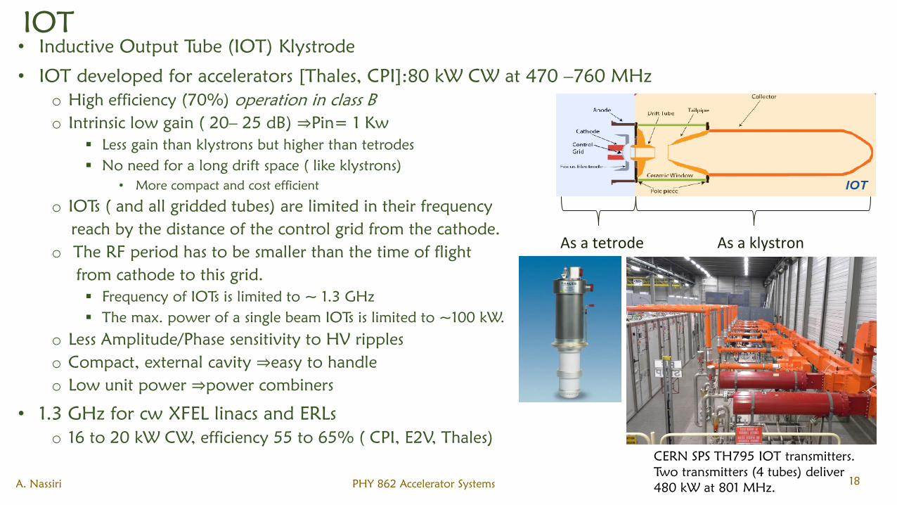
IOT
• Inductive Output Tube (IOT) Klystrode
• IOT developed for accelerators [Thales, CPI]:80 kW CW at 470 –760 MHz
o High efficiency (70%) operation in class B
o Intrinsic low gain ( 20– 25 dB) ⇒Pin= 1 Kw
Less gain than klystrons but higher than tetrodes
No need for a long drift space ( like klystrons)
• More compact and cost efficient
o IOTs ( and all gridded tubes) are limited in their frequency
reach by the distance of the control grid from the cathode.
o The RF period has to be smaller than the time of flight
from cathode to this grid.
Frequency of IOTs is limited to ~ 1.3 GHz
The max. power of a single beam IOTs is limited to ~100 kW.
o Less Amplitude/Phase sensitivity to HV ripples
o Compact, external cavity ⇒easy to handle
o Low unit power ⇒power combiners
• 1.3 GHz for cw XFEL linacs and ERLs
o 16 to 20 kW CW, efficiency 55 to 65% ( CPI, E2V, Thales)
As a tetrode As a klystron
A. Nassiri PHY 862 Accelerator Systems 18
CERN SPS TH795 IOT transmitters.
Two transmitters (4 tubes) deliver
480 kW at 801 MHz.
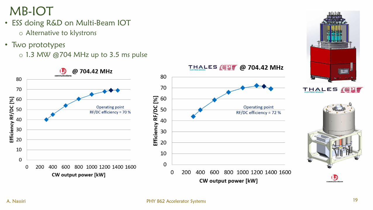
MB-IOT
• ESS doing R&D on Multi-Beam IOT
o Alternative to klystrons
• Two prototypes
o 1.3 MW @704 MHz up to 3.5 ms pulse
A. Nassiri PHY 862 Accelerator Systems 19
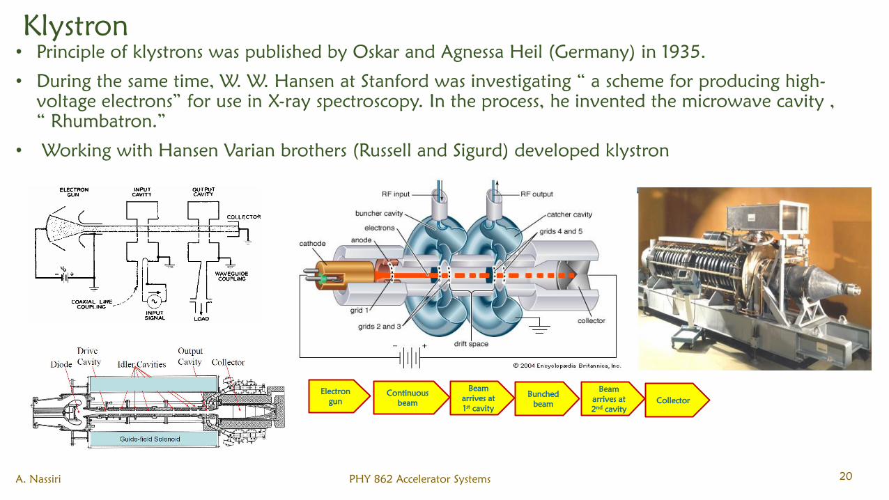
Klystron
• Principle of klystrons was published by Oskar and Agnessa Heil (Germany) in 1935.
• During the same time, W. W. Hansen at Stanford was investigating “ a scheme for producing high-
voltage electrons” for use in X-ray spectroscopy. In the process, he invented the microwave cavity ,
“ Rhumbatron.”
• Working with Hansen Varian brothers (Russell and Sigurd) developed klystron
A. Nassiri PHY 862 Accelerator Systems 20
Beam
arrives at
2nd
cavity
Beam
arrives at
1st
cavity
Bunched
beam
Electron
gun
Continuous
beamCollector
RF and Microwave
• Both RF and Microwave are used to represent frequency ranges in the electromagnetic spectrum.
Both are used for many similar as well as different applications. RF is the short form for 'Radio
Frequency' signal.
• RF (Radio Frequency)
o EM spectrum has been classified into eight regions based on radiation intensity. The major divisions are into radio
spectrum and optical spectrum. Radio spectrum covers radio waves, microwaves and terahertz radiations. Optical
spectrum covers infrared, visible, ultra violet, X-rays and gamma radiations. Radio waves range from 3 KHz to 300
GHz. Hence RF. starts from much lower than the microwave starting range.
o In radio waves antenna wavelength varies from hundreds of meters to about 1 millimeter.
• Microwave
o The term "micro" means very small. It is basically millionth part of a unit. The term Microwave is used to identify EM
waves above 1GHz in frequency because of short physical wavelength of these frequencies. Microwaves are basically
radio frequency(RF) waves. However there is difference between RF and microwave as far as operating range and
applications are concerned. Microwaves range starts from 300MHz to 300GHz.
o Most of the microwave applications range up to 100 GHz. Following are the unique features of the microwaves:
• High antenna gain and directivity
• Large Bandwidth
• It travels by LOS(Line Of Sight)
• In 1-10GHz range Microwaves noise level is very low and hence very low signal can also be easily detected at receiver
• Microwaves penetrate ionosphere with less attenuation as well as less distortion.
A. Nassiri PHY 862 Accelerator Systems 21
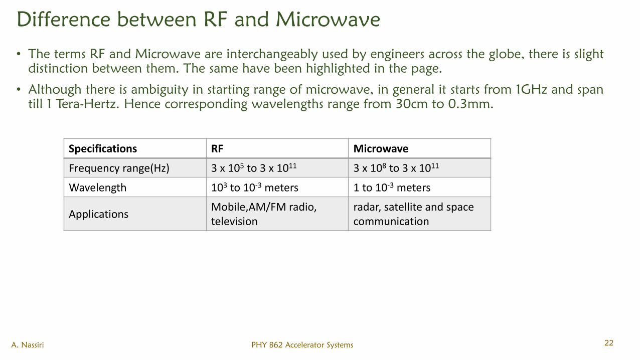
Difference between RF and Microwave
• The terms RF and Microwave are interchangeably used by engineers across the globe, there is slight
distinction between them. The same have been highlighted in the page.
• Although there is ambiguity in starting range of microwave, in general it starts from 1GHz and span
till 1 Tera-Hertz. Hence corresponding wavelengths range from 30cm to 0.3mm.
Specifications RF Microwave
Frequency range(Hz) 3 x 10⁵ to 3 x 10¹¹ 3 x 10⁸ to 3 x 10¹¹
Wavelength 103 to 10-3 meters 1 to 10-3 meters
ApplicationsMobile,AM/FM radio, television
radar, satellite and space communication
A. Nassiri PHY 862 Accelerator Systems 22
Properties of Microwaves
1. Microwave is an electromagnetic radiation of short wavelength.
2. They can reflect by conducting surfaces just like optical waves since they travel in straight line.
3. Microwave currents flow through a thin outer layer of an ordinary cable.
4. Microwaves are easily attenuated within short distances.
5. They are not reflected by ionosphere
A. Nassiri PHY 862 Accelerator Systems 23
Advantages and Limitations
• Increased bandwidth availability
o Microwaves have large bandwidths compared to the common bands like short waves (SW), ultrahigh
frequency (UHF) waves, etc.
o For example, the microwaves extending from = 1 cm - = 10 cm (i.e) from 30,000 MHz – 3000 MHz,
this region has a bandwidth of 27,000 MHz.
• Improved directive properties
o The second advantage of microwaves is their ability to use high gain directive antennas, any EM wave can
be focused in a specified direction (Just as the focusing of light rays with lenses or reflectors)
• Fading effect and reliability
o Fading effect due to the variation in the transmission medium is more effective at low frequency.
o Due to the Line of Sight (LOS) propagation and high frequencies, there is less fading effect and hence
microwave communication is more reliable.
• Power requirements
o Transmitter / receiver power requirements are pretty low at microwave frequencies compared to that at
short wave band.
A. Nassiri PHY 862 Accelerator Systems 24
Advantages and Limitations
• Transparency property
o Microwave frequency band ranging from 300 MHz – 10 GHz are capable of freely propagating through
the atmosphere.
o The presence of such a transparent window in a microwave band facilitates the study of microwave
radiation from the sun and stars in radio astronomical research of space.
• Applications
o Scientific – Accelerators
o Telecommunication: Intercontinental Telephone and TV, space communication (Earth – to – space and
space – to – Earth), telemetry communication link for railways etc.
o Radars: detect aircraft, track / guide supersonic missiles, observe and track weather patterns, air traffic
control (ATC), burglar alarms, garage door openers, police speed detectors etc.
A. Nassiri PHY 862 Accelerator Systems 25
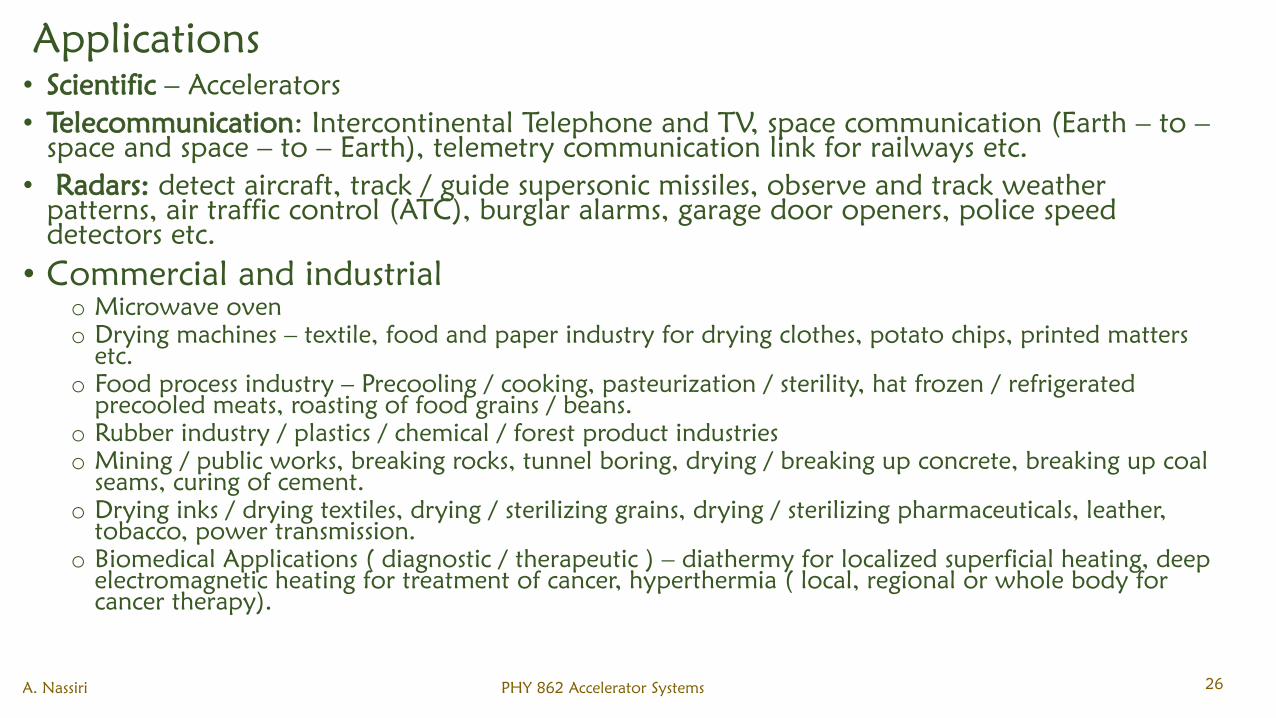
Applications
• Scientific – Accelerators
• Telecommunication: Intercontinental Telephone and TV, space communication (Earth – to –
space and space – to – Earth), telemetry communication link for railways etc.
• Radars: detect aircraft, track / guide supersonic missiles, observe and track weather
patterns, air traffic control (ATC), burglar alarms, garage door openers, police speed
detectors etc.
• Commercial and industrial
o Microwave oven
o Drying machines – textile, food and paper industry for drying clothes, potato chips, printed matters
etc.
o Food process industry – Precooling / cooking, pasteurization / sterility, hat frozen / refrigerated
precooled meats, roasting of food grains / beans.
o Rubber industry / plastics / chemical / forest product industries
o Mining / public works, breaking rocks, tunnel boring, drying / breaking up concrete, breaking up coal
seams, curing of cement.
o Drying inks / drying textiles, drying / sterilizing grains, drying / sterilizing pharmaceuticals, leather,
tobacco, power transmission.
o Biomedical Applications ( diagnostic / therapeutic ) – diathermy for localized superficial heating, deep
electromagnetic heating for treatment of cancer, hyperthermia ( local, regional or whole body for
cancer therapy).
A. Nassiri PHY 862 Accelerator Systems 26
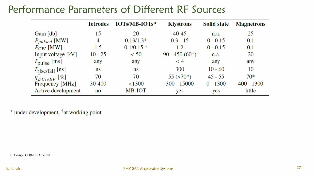
Performance Parameters of Different RF Sources
A. Nassiri PHY 862 Accelerator Systems 27
F. Gerigk, CERN, IPAC2018
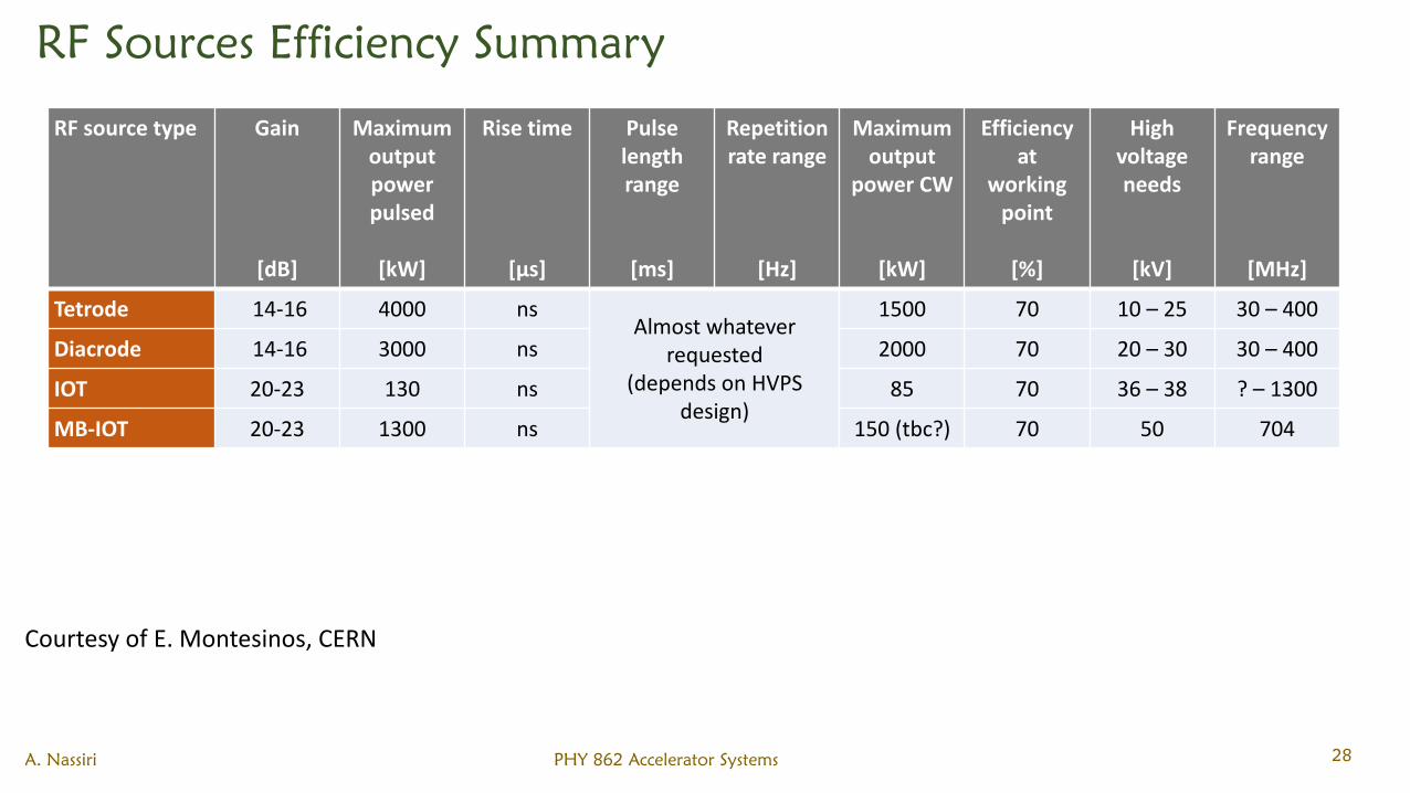
RF Sources Efficiency Summary
A. Nassiri PHY 862 Accelerator Systems 28
RF source type Gain
[dB]
Maximum output power pulsed
[kW]
Rise time
[µs]
Pulse length range
[ms]
Repetition rate range
[Hz]
Maximumoutput
power CW
[kW]
Efficiency at
working point
[%]
High voltage needs
[kV]
Frequency range
[MHz]
Tetrode 14-16 4000 nsAlmost whatever
requested(depends on HVPS
design)
1500 70 10 – 25 30 – 400
Diacrode 14-16 3000 ns 2000 70 20 – 30 30 – 400
IOT 20-23 130 ns 85 70 36 – 38 ? – 1300
MB-IOT 20-23 1300 ns 150 (tbc?) 70 50 704
Courtesy of E. Montesinos, CERN
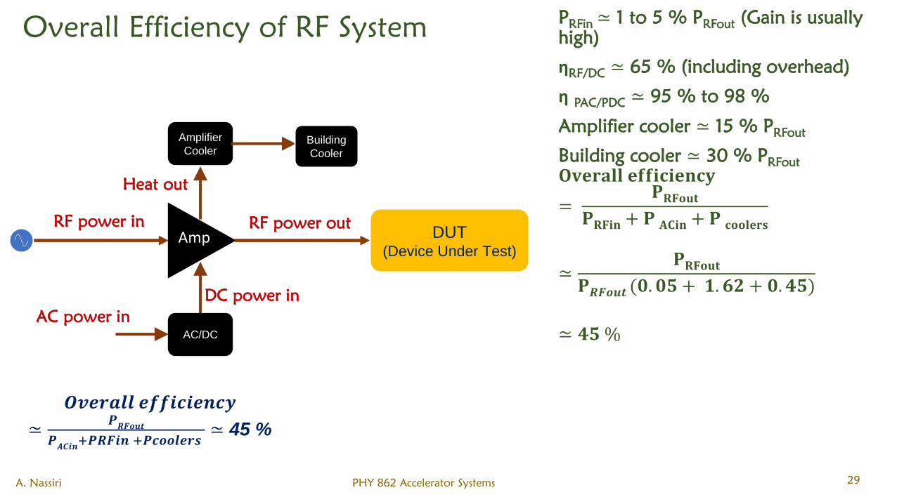
Overall Efficiency of RF System
A. Nassiri PHY 862 Accelerator Systems 29
RF power in
DC power in
Heat out
RF power out
AC/DC
AC power in
Amplifier
CoolerBuilding
Cooler
DUT(Device Under Test)
𝑶𝒗𝒆𝒓𝒂𝒍𝒍 𝒆𝒇𝒇𝒊𝒄𝒊𝒆𝒏𝒄𝒚
≃𝑷𝑹𝑭𝒐𝒖𝒕
𝑷𝑨𝑪𝒊𝒏
+𝑷𝑹𝑭𝒊𝒏 +𝑷𝒄𝒐𝒐𝒍𝒆𝒓𝒔≃ 45 %
PRFin
≃ 1 to 5 % PRFout
(Gain is usually
high)
ηRF/DC
≃ 65 % (including overhead)
ηPAC/PDC
≃ 95 % to 98 %
Amplifier cooler ≃ 15 % PRFout
Building cooler ≃ 30 % PRFout
𝐎𝐯𝐞𝐫𝐚𝐥𝐥 𝐞𝐟𝐟𝐢𝐜𝐢𝐞𝐧𝐜𝐲
=𝐏𝐑𝐅𝐨𝐮𝐭
𝐏𝐑𝐅𝐢𝐧 + 𝐏 𝐀𝐂𝐢𝐧+ 𝐏 𝐜𝐨𝐨𝐥𝐞𝐫𝐬
≃𝐏𝐑𝐅𝐨𝐮𝐭
𝐏𝑹𝑭𝒐𝒖𝒕 (𝟎. 𝟎𝟓 + 𝟏. 𝟔𝟐 + 𝟎. 𝟒𝟓)
≃ 𝟒𝟓 %
Amp
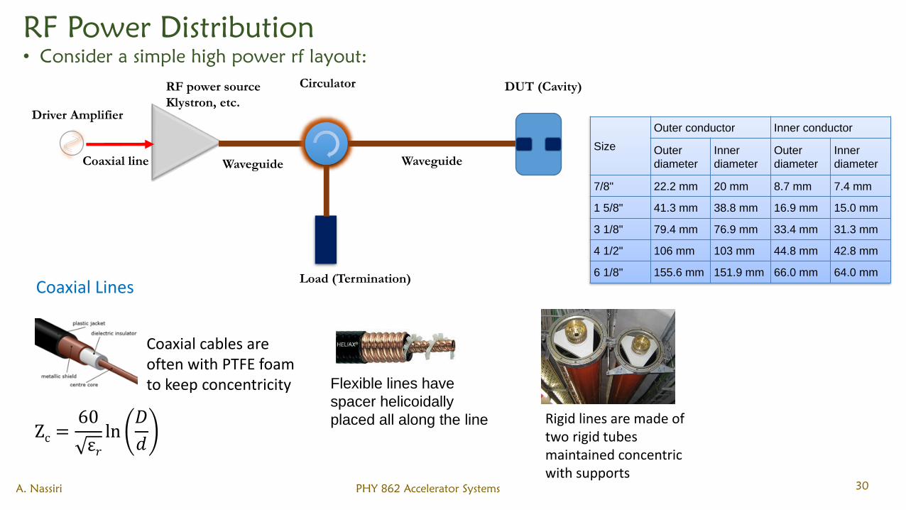
RF Power Distribution
• Consider a simple high power rf layout:
A. Nassiri PHY 862 Accelerator Systems 30
Driver Amplifier
CirculatorRF power source
Klystron, etc.
DUT (Cavity)
Load (Termination)
Coaxial line Waveguide Waveguide
Coaxial Lines
Zc =60
ε𝑟ln
𝐷
𝑑
Coaxial cables are often with PTFE foam to keep concentricity Flexible lines have
spacer helicoidally
placed all along the line Rigid lines are made of two rigid tubes maintained concentric with supports
Size
Outer conductor Inner conductor
Outer
diameter
Inner
diameter
Outer
diameter
Inner
diameter
7/8" 22.2 mm 20 mm 8.7 mm 7.4 mm
1 5/8" 41.3 mm 38.8 mm 16.9 mm 15.0 mm
3 1/8" 79.4 mm 76.9 mm 33.4 mm 31.3 mm
4 1/2" 106 mm 103 mm 44.8 mm 42.8 mm
6 1/8" 155.6 mm 151.9 mm 66.0 mm 64.0 mm
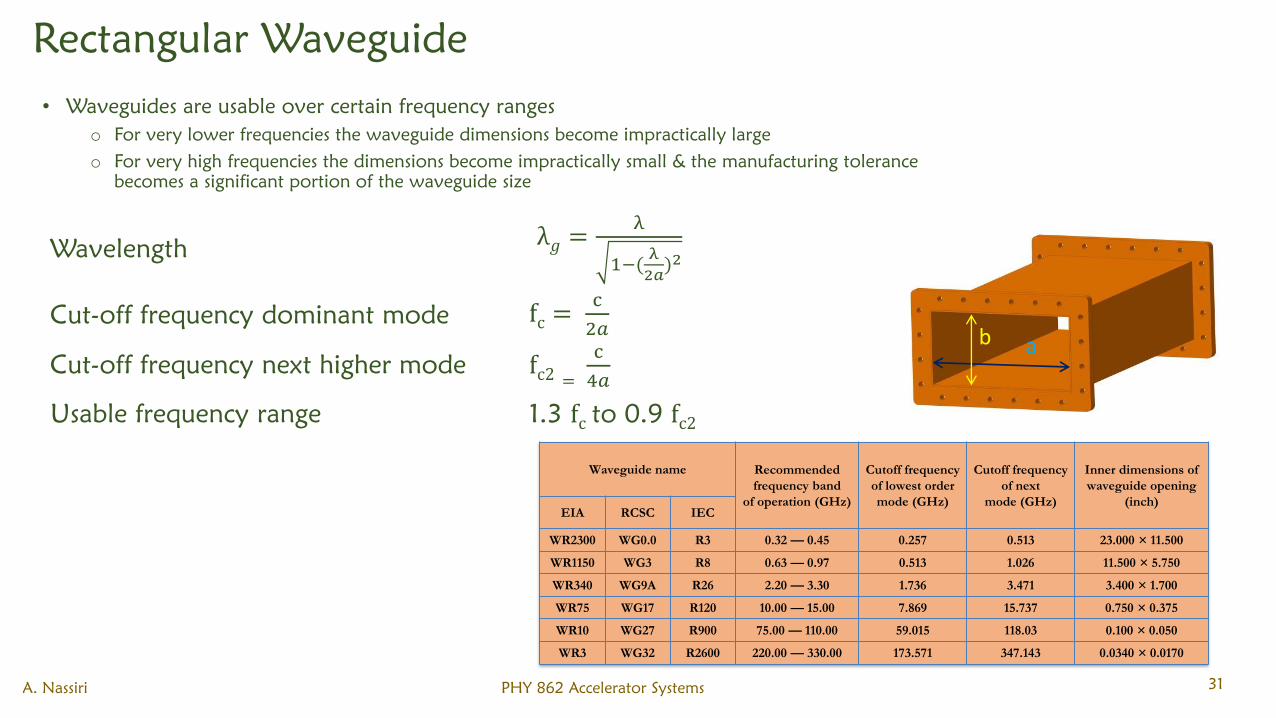
Rectangular Waveguide
A. Nassiri PHY 862 Accelerator Systems 31
b a
• Waveguides are usable over certain frequency ranges
o For very lower frequencies the waveguide dimensions become impractically large
o For very high frequencies the dimensions become impractically small & the manufacturing tolerance
becomes a significant portion of the waveguide size
Wavelengthλ𝑔 =
λ
1−(λ
2𝑎)2
Cut-off frequency dominant mode fc =c
2𝑎
Cut-off frequency next higher mode fc2 =
c
4𝑎
Usable frequency range 1.3 fc to 0.9 fc2
Waveguide name Recommended
frequency band
of operation (GHz)
Cutoff frequency
of lowest order
mode (GHz)
Cutoff frequency
of next
mode (GHz)
Inner dimensions of
waveguide opening
(inch)EIA RCSC IEC
WR2300 WG0.0 R3 0.32 — 0.45 0.257 0.513 23.000 × 11.500
WR1150 WG3 R8 0.63 — 0.97 0.513 1.026 11.500 × 5.750
WR340 WG9A R26 2.20 — 3.30 1.736 3.471 3.400 × 1.700
WR75 WG17 R120 10.00 — 15.00 7.869 15.737 0.750 × 0.375
WR10 WG27 R900 75.00 — 110.00 59.015 118.03 0.100 × 0.050
WR3 WG32 R2600 220.00 — 330.00 173.571 347.143 0.0340 × 0.0170
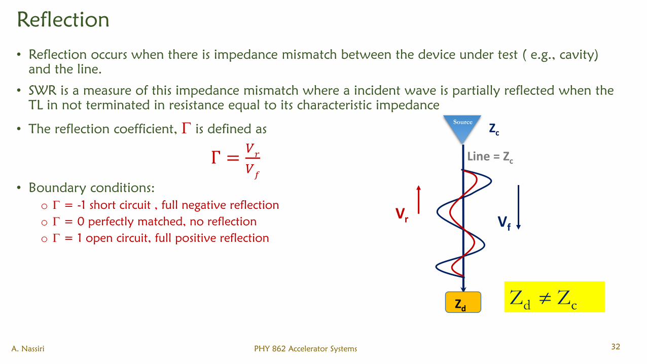
Reflection
• Reflection occurs when there is impedance mismatch between the device under test ( e.g., cavity)
and the line.
• SWR is a measure of this impedance mismatch where a incident wave is partially reflected when the
TL in not terminated in resistance equal to its characteristic impedance
• The reflection coefficient, is defined as
Г =𝑉𝑟
𝑉𝑓
• Boundary conditions:
o = -1 short circuit , full negative reflection
o = 0 perfectly matched, no reflection
o = 1 open circuit, full positive reflection
A. Nassiri PHY 862 Accelerator Systems 32
Zc
Line = Zc
Zd
VfVr
Zd Zc
Source
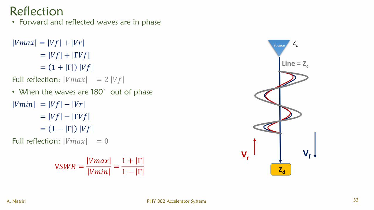
Reflection
• Forward and reflected waves are in phase
𝑉𝑚𝑎𝑥 = 𝑉𝑓 + 𝑉𝑟
= 𝑉𝑓 + Г𝑉𝑓
= 1 + Г 𝑉𝑓
Full reflection: 𝑉𝑚𝑎𝑥 = 2 𝑉𝑓
• When the waves are 180
out of phase
𝑉𝑚𝑖𝑛 = 𝑉𝑓 − 𝑉𝑟
= 𝑉𝑓 − Г𝑉𝑓
= 1 − Г 𝑉𝑓
Full reflection: 𝑉𝑚𝑎𝑥 = 0
V𝑆𝑊𝑅 =𝑉𝑚𝑎𝑥
𝑉𝑚𝑖𝑛=1 + Г
1 − Г
A. Nassiri PHY 862 Accelerator Systems 33
Line = Zc
Zd
VfVr
Source Zc
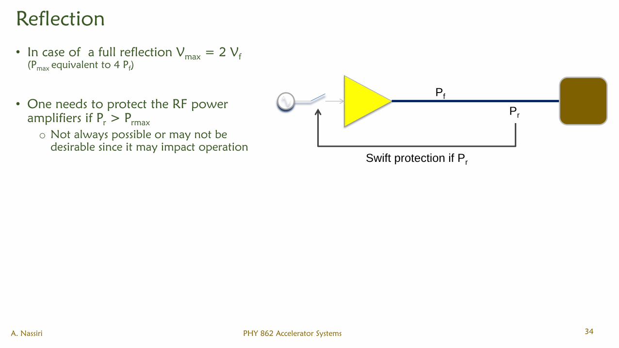
Reflection
• In case of a full reflection Vmax
= 2 Vf
(Pmax
equivalent to 4 Pf)
• One needs to protect the RF power
amplifiers if Pr> P
rmax
o Not always possible or may not be
desirable since it may impact operation
A. Nassiri PHY 862 Accelerator Systems 34
Pf
Pr
Swift protection if Pr
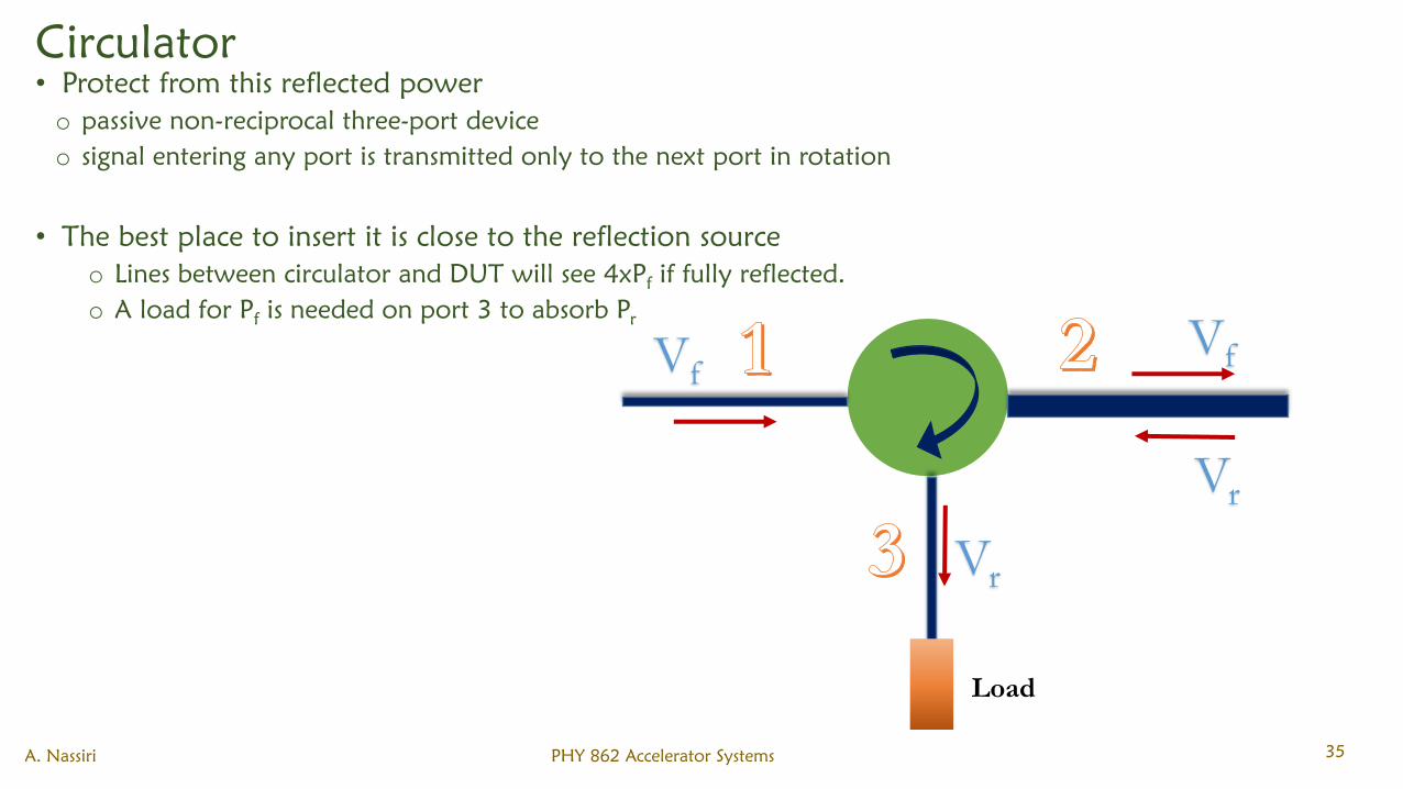
Circulator
• Protect from this reflected power
o passive non-reciprocal three-port device
o signal entering any port is transmitted only to the next port in rotation
• The best place to insert it is close to the reflection source
o Lines between circulator and DUT will see 4xPfif fully reflected.
o A load for Pfis needed on port 3 to absorb P
r
A. Nassiri PHY 862 Accelerator Systems 35
Vr
Vf
Vr
Vf
Load
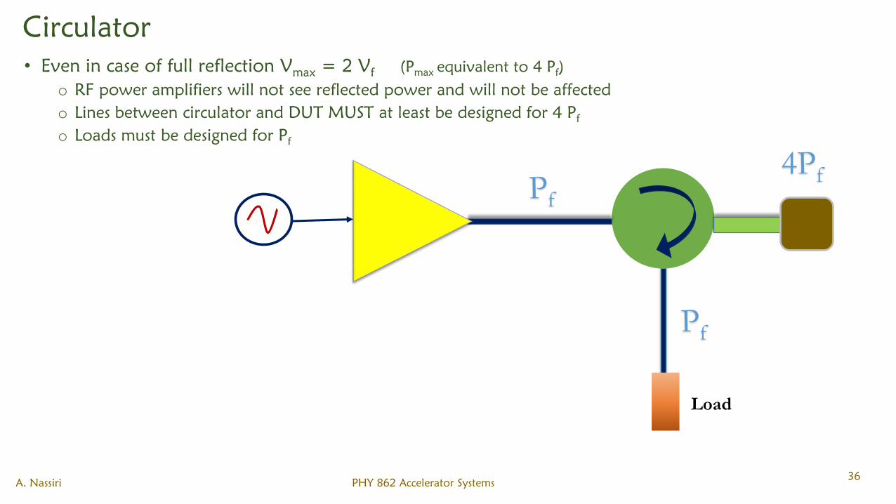
Circulator
• Even in case of full reflection Vmax
= 2 Vf
(Pmax
equivalent to 4 Pf)
o RF power amplifiers will not see reflected power and will not be affected
o Lines between circulator and DUT MUST at least be designed for 4 Pf
o Loads must be designed for Pf
A. Nassiri PHY 862 Accelerator Systems36
Pf
4PfPf
Load
Limitations of Microwave Tubes
• Performance is limited by a number of factors including:
o Heat dissipation
o Voltage breakdown
o Output window failure
o Multipactor discharge
• The RF structures and the windows of microwave tubes generally scale inversely with frequency.
• The maximum CW or average power that can be handled by a particular type of tube depends
upon the maximum temperature that the internal surfaces can be allowed to reach.
• This temperature is independent of the frequency, so the power that can be dissipated varies
inversely with the frequency.
• Gyrotrons can handle a higher power of the same frequency than klystrons because they have
simpler structures and, if operated in a higher order mode, their structures are larger for a given
frequency.
• The power is also limited by the power that can be generated by an electron gun and formed into a
beam. The beam diameter scales inversely with frequency and the beam current density is
determined by the maximum attainable magnetic focusing field.
• Since the field is independent of frequency the beam current scales inversely with the square of the
frequency
A. Nassiri PHY 862 Accelerator Systems 37
Limitations of Microwave Tubes
• The beam voltage is related to the current by the gun perveance ൗ𝑰 𝑽𝟏.𝟓which typically in the
range of 1.0 to 2.0 for power tubes.
• The maximum gun voltage is limited by the breakdown field in the gun and therefore varies inversely
with frequency for constant perveance.
• The maximum power obtainable from a tube is 𝑓−2.5 𝑡𝑜 −3.0 depending on the assumptions made.
• The efficiencies of tubes tend to fall with increasing frequency. This is partly because the RF losses
increase with frequency and partly because of the design compromises that must be made at higher
frequencies.
• The maximum power obtainable from a pulsed tube is often determined by the power-handling
capability of the output window. The output window of an external cavity klystron is in the form of a
cylinder within the cavity and close to the output gap. This arrangement is limited to powers of about
70 kW. At higher power levels integral cavities are used and the power is brought out through
waveguide or coaxial line windows.
• Very high power klystrons commonly have two windows in parallel to handle the full output power.
• Windows can be destroyed by excessive reflected power, by arcs in the output waveguide, by X-ray
bombardment, and by the multipactor discharges described in the next Section. The basic cause of
failure is overheating and it is usual to monitor the window temperature and to provide reverse
power and waveguide and cavity arc detectors.
A. Nassiri PHY 862 Accelerator Systems 38
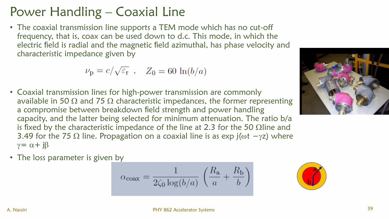
Power Handling – Coaxial Line
• The coaxial transmission line supports a TEM mode which has no cut-off
frequency, that is, coax can be used down to d.c. This mode, in which the
electric field is radial and the magnetic field azimuthal, has phase velocity and
characteristic impedance given by
• Coaxial transmission lines for high-power transmission are commonly
available in 50 and 75 characteristic impedances, the former representing
a compromise between breakdown field strength and power handling
capacity, and the latter being selected for minimum attenuation. The ratio b/a
is fixed by the characteristic impedance of the line at 2.3 for the 50 line and
3.49 for the 75 line. Propagation on a coaxial line is as exp j(t −z) where
= + j
• The loss parameter is given by
A. Nassiri PHY 862 Accelerator Systems 39
a
b
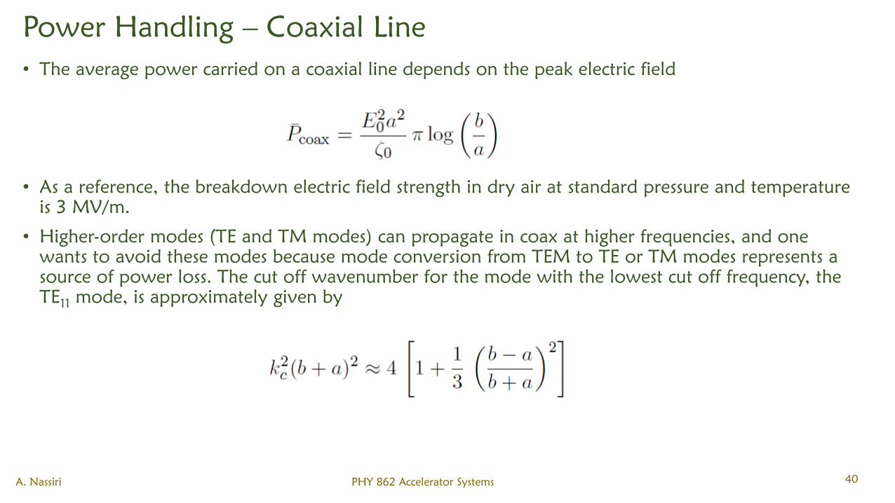
Power Handling – Coaxial Line
• The average power carried on a coaxial line depends on the peak electric field
• As a reference, the breakdown electric field strength in dry air at standard pressure and temperature
is 3 MV/m.
• Higher-order modes (TE and TM modes) can propagate in coax at higher frequencies, and one
wants to avoid these modes because mode conversion from TEM to TE or TM modes represents a
source of power loss. The cut off wavenumber for the mode with the lowest cut off frequency, the
TE11
mode, is approximately given by
A. Nassiri PHY 862 Accelerator Systems 40
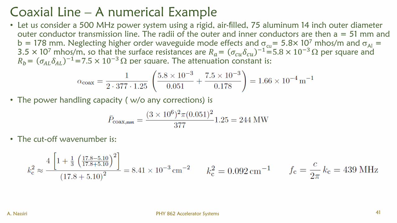
Coaxial Line – A numerical Example
• Let us consider a 500 MHz power system using a rigid, air-filled, 75 aluminum 14 inch outer diameter
outer conductor transmission line. The radii of the outer and inner conductors are then a = 51 mm and
b = 178 mm. Neglecting higher order waveguide mode effects and cu
= 5.8× 10⁷
mhos/m and Al
=
3.5 × 10⁷
mhos/m, so that the surface resistances are 𝑅𝑎= 𝜎𝑐𝑢𝛿𝑐𝑢−1
=5.8 × 10⁻³ per square and
𝑅𝑏= 𝜎𝐴𝐿𝛿𝐴𝐿−1
=7.5 × 10⁻³ per square. The attenuation constant is:
• The power handling capacity ( w/o any corrections) is
• The cut-off wavenumber is:
A. Nassiri PHY 862 Accelerator Systems 41
Coaxial Line – A numerical Example
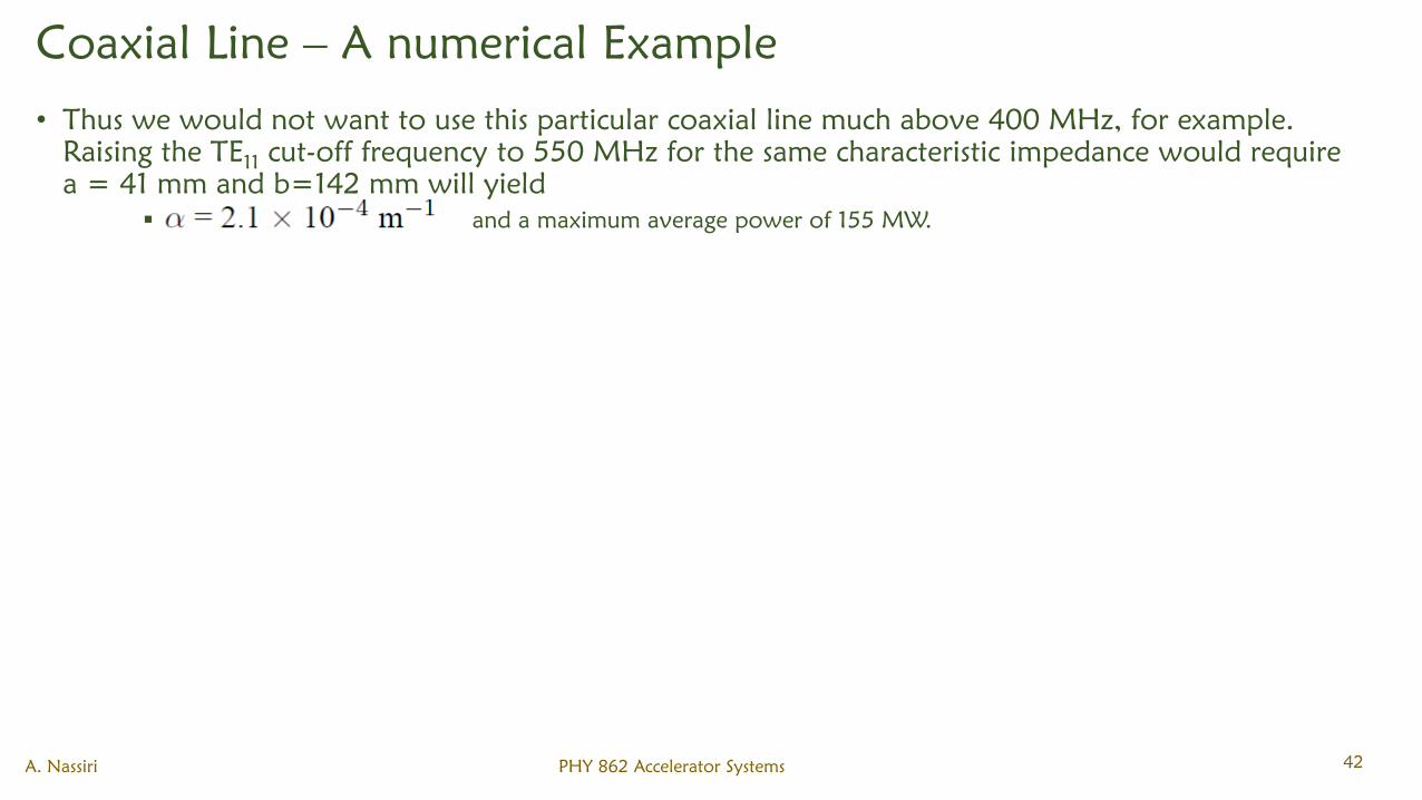
• Thus we would not want to use this particular coaxial line much above 400 MHz, for example.
Raising the TE11
cut-off frequency to 550 MHz for the same characteristic impedance would require
a = 41 mm and b=142 mm will yield
and a maximum average power of 155 MW.
A. Nassiri PHY 862 Accelerator Systems 42
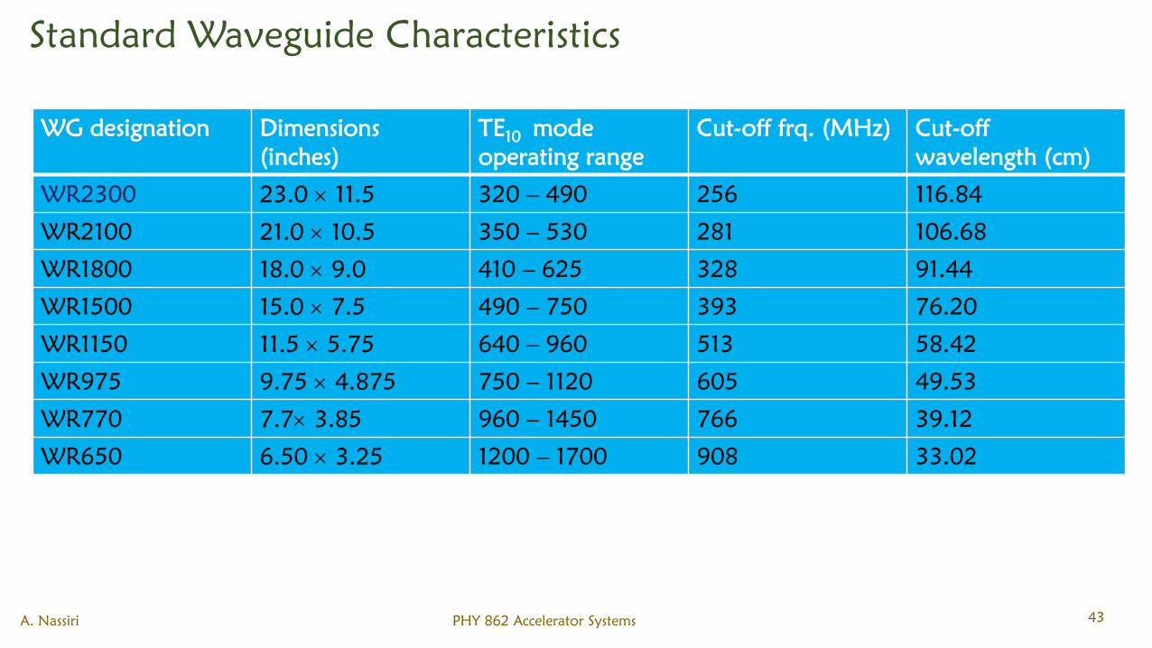
Standard Waveguide Characteristics
A. Nassiri PHY 862 Accelerator Systems 43
WG designation Dimensions
(inches)
TE10
mode
operating range
Cut-off frq. (MHz) Cut-off
wavelength (cm)
WR2300 23.0 11.5 320 – 490 256 116.84
WR2100 21.0 10.5 350 – 530 281 106.68
WR1800 18.0 9.0 410 – 625 328 91.44
WR1500 15.0 7.5 490 – 750 393 76.20
WR1150 11.5 5.75 640 – 960 513 58.42
WR975 9.75 4.875 750 – 1120 605 49.53
WR770 7.7 3.85 960 – 1450 766 39.12
WR650 6.50 3.25 1200 – 1700 908 33.02
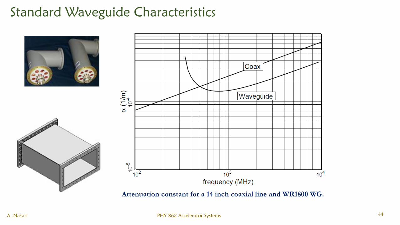
Standard Waveguide Characteristics
A. Nassiri PHY 862 Accelerator Systems 44
Attenuation constant for a 14 inch coaxial line and WR1800 WG.
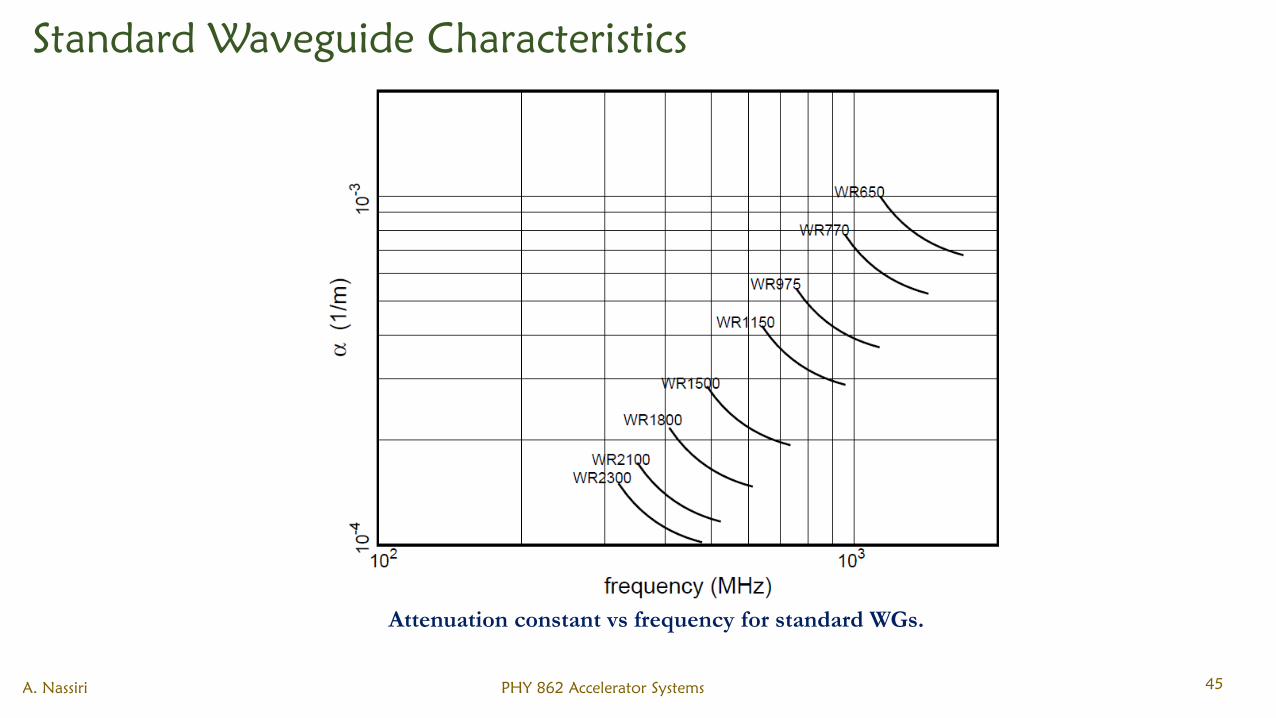
Standard Waveguide Characteristics
A. Nassiri PHY 862 Accelerator Systems 45
Attenuation constant vs frequency for standard WGs.
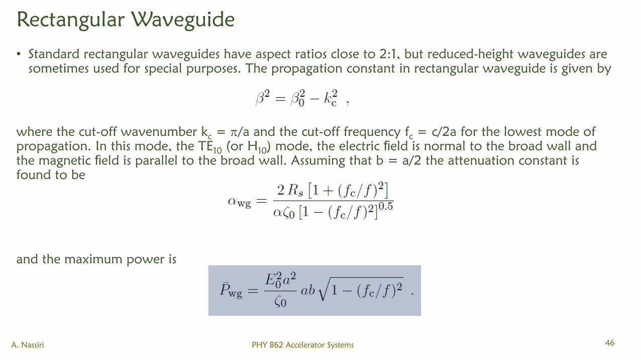
Rectangular Waveguide
• Standard rectangular waveguides have aspect ratios close to 2:1, but reduced-height waveguides are
sometimes used for special purposes. The propagation constant in rectangular waveguide is given by
where the cut-off wavenumber kc= /a and the cut-off frequency f
c= c/2a for the lowest mode of
propagation. In this mode, the TE10
(or H10
) mode, the electric field is normal to the broad wall and
the magnetic field is parallel to the broad wall. Assuming that b = a/2 the attenuation constant is
found to be
and the maximum power is
A. Nassiri PHY 862 Accelerator Systems 46
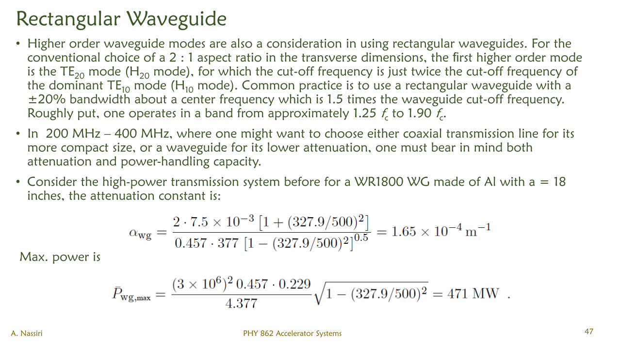
Rectangular Waveguide
• Higher order waveguide modes are also a consideration in using rectangular waveguides. For the
conventional choice of a 2 : 1 aspect ratio in the transverse dimensions, the first higher order mode
is the TE20
mode (H20
mode), for which the cut-off frequency is just twice the cut-off frequency of
the dominant TE10
mode (H10
mode). Common practice is to use a rectangular waveguide with a
±20% bandwidth about a center frequency which is 1.5 times the waveguide cut-off frequency.
Roughly put, one operates in a band from approximately 1.25 fcto 1.90 f
c.
• In 200 MHz – 400 MHz, where one might want to choose either coaxial transmission line for its
more compact size, or a waveguide for its lower attenuation, one must bear in mind both
attenuation and power-handling capacity.
• Consider the high-power transmission system before for a WR1800 WG made of Al with a = 18
inches, the attenuation constant is:
Max. power is
A. Nassiri PHY 862 Accelerator Systems 47
Rectangular Waveguide
• So operating at 500 MHz, choosing a waveguide over a coax is obvious.
• In order to avoid higher order waveguide mode losses, the diameter of the coax must be reduced,
leading to higher attenuation and lower power-handling capacity as shown above. For short
distances of transmission, however, the higher losses of coaxial transmission lines may be acceptable.
A. Nassiri PHY 862 Accelerator Systems 48
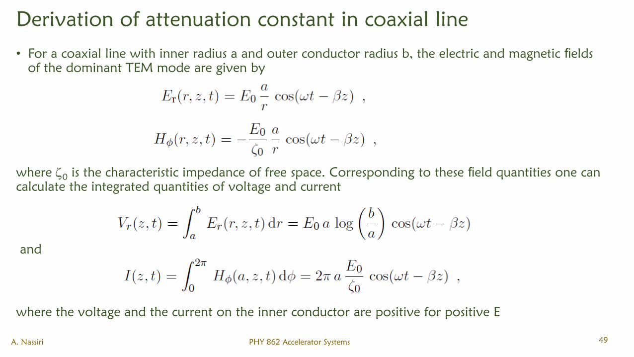
Derivation of attenuation constant in coaxial line
• For a coaxial line with inner radius a and outer conductor radius b, the electric and magnetic fields
of the dominant TEM mode are given by
where 0
is the characteristic impedance of free space. Corresponding to these field quantities one can
calculate the integrated quantities of voltage and current
and
where the voltage and the current on the inner conductor are positive for positive E
A. Nassiri PHY 862 Accelerator Systems 49
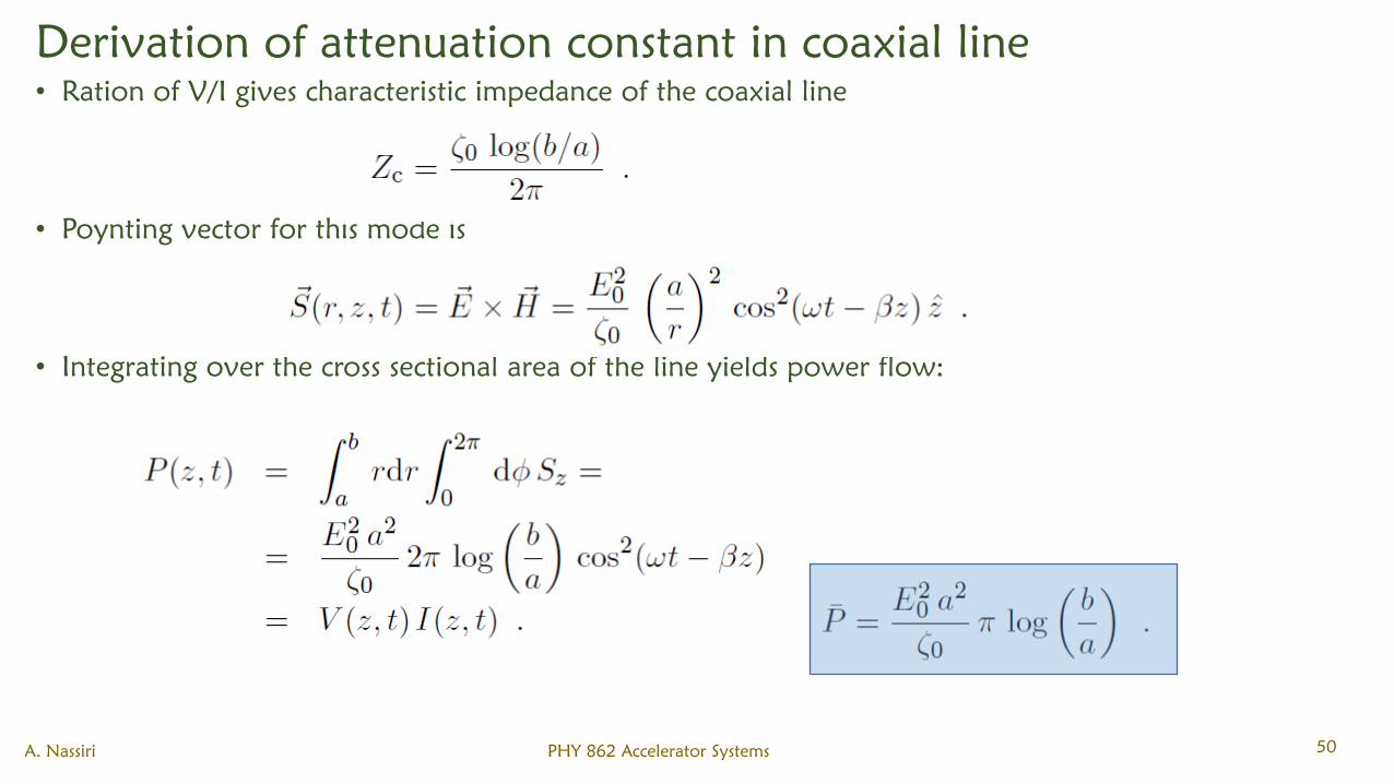
Derivation of attenuation constant in coaxial line
• Ration of V/I gives characteristic impedance of the coaxial line
• Poynting vector for this mode is
• Integrating over the cross sectional area of the line yields power flow:
A. Nassiri PHY 862 Accelerator Systems 50
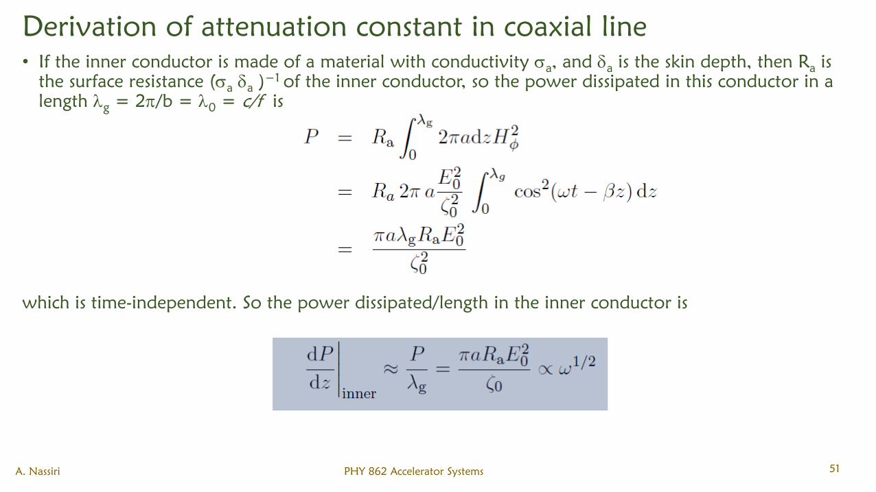
Derivation of attenuation constant in coaxial line
• If the inner conductor is made of a material with conductivity a, and
ais the skin depth, then R
ais
the surface resistance (a
a)−1
of the inner conductor, so the power dissipated in this conductor in a
length g
= 2/b = 0
= c/f is
which is time-independent. So the power dissipated/length in the inner conductor is
A. Nassiri PHY 862 Accelerator Systems 51
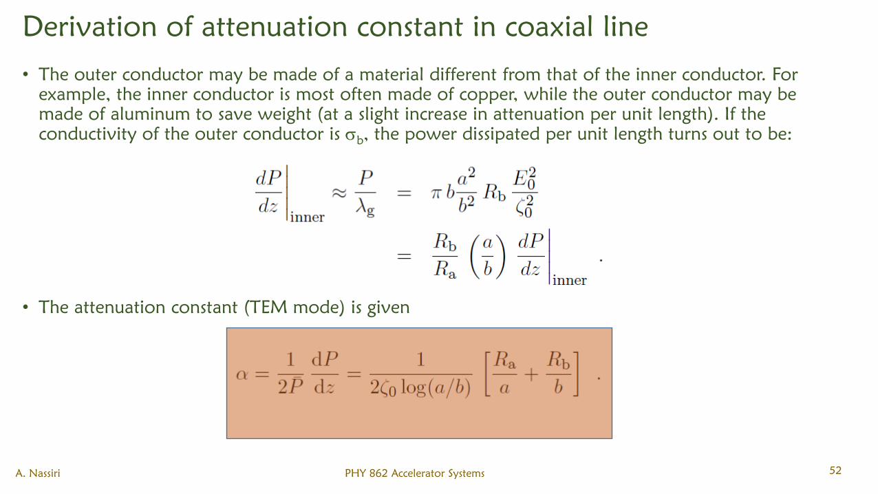
Derivation of attenuation constant in coaxial line
• The outer conductor may be made of a material different from that of the inner conductor. For
example, the inner conductor is most often made of copper, while the outer conductor may be
made of aluminum to save weight (at a slight increase in attenuation per unit length). If the
conductivity of the outer conductor is b, the power dissipated per unit length turns out to be:
• The attenuation constant (TEM mode) is given
A. Nassiri PHY 862 Accelerator Systems 52
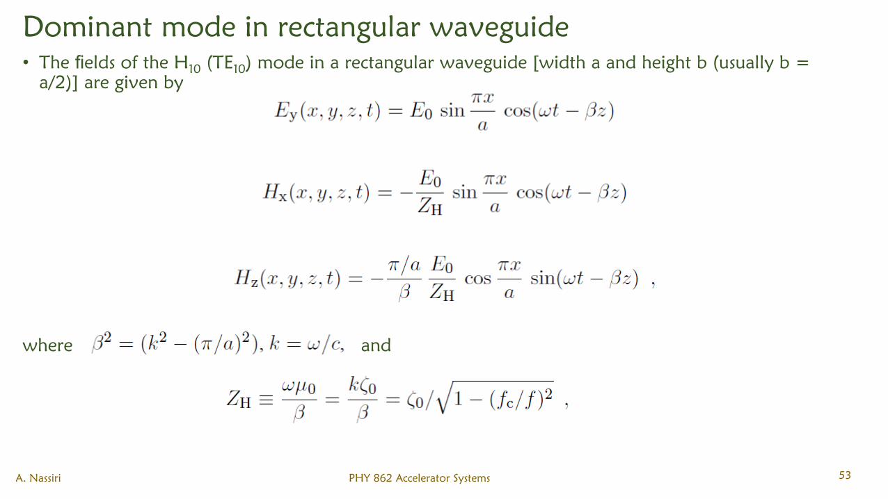
Dominant mode in rectangular waveguide
• The fields of the H10
(TE10
) mode in a rectangular waveguide [width a and height b (usually b =
a/2)] are given by
where and
A. Nassiri PHY 862 Accelerator Systems 53
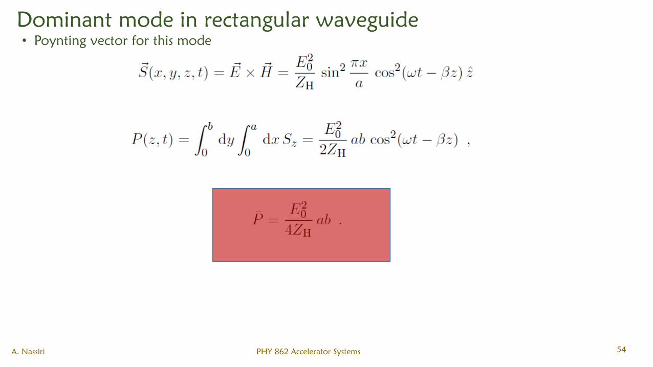
Dominant mode in rectangular waveguide
• Poynting vector for this mode
A. Nassiri PHY 862 Accelerator Systems 54
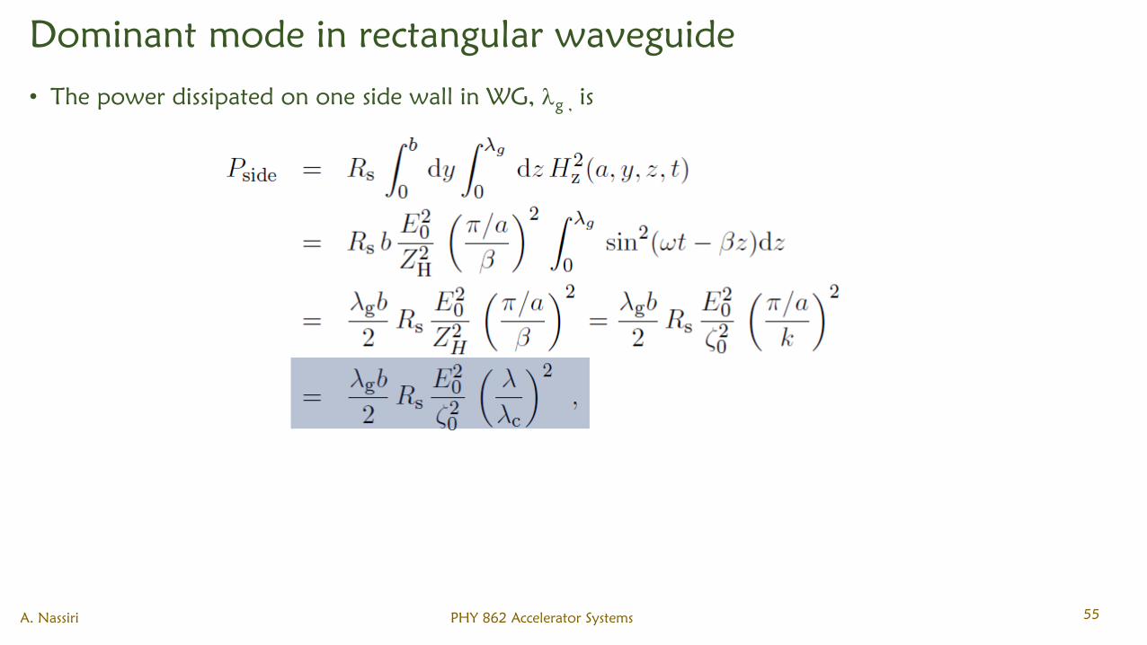
Dominant mode in rectangular waveguide
• The power dissipated on one side wall in WG, g ,
is
A. Nassiri PHY 862 Accelerator Systems 55
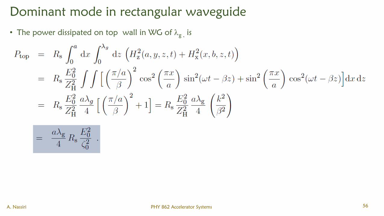
Dominant mode in rectangular waveguide
• The power dissipated on top wall in WG of g ,
is
A. Nassiri PHY 862 Accelerator Systems 56
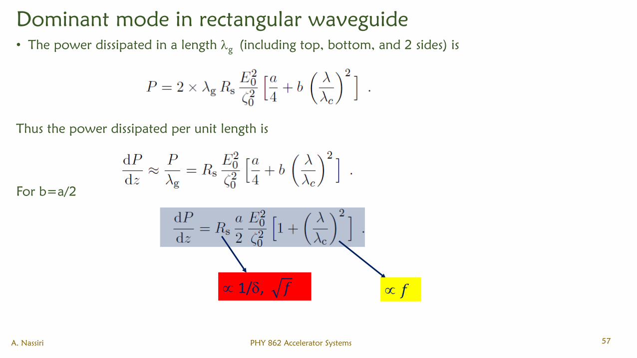
Dominant mode in rectangular waveguide
• The power dissipated in a length g
(including top, bottom, and 2 sides) is
Thus the power dissipated per unit length is
For b=a/2
A. Nassiri PHY 862 Accelerator Systems 57
1/, 𝑓 𝑓
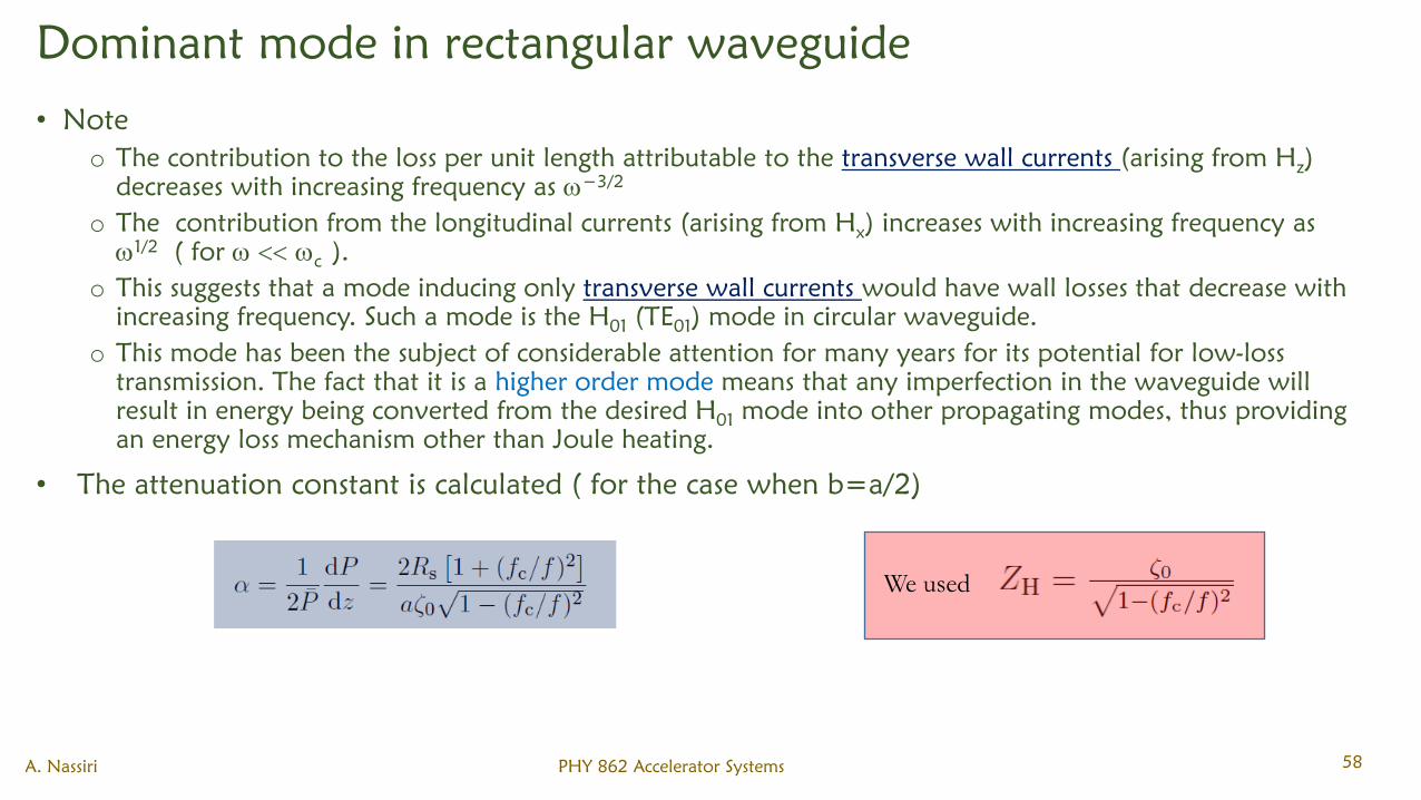
Dominant mode in rectangular waveguide
• Note
o The contribution to the loss per unit length attributable to the transverse wall currents (arising from Hz)
decreases with increasing frequency as −3/2
o The contribution from the longitudinal currents (arising from Hx) increases with increasing frequency as
1/2( for
c ).
o This suggests that a mode inducing only transverse wall currents would have wall losses that decrease with
increasing frequency. Such a mode is the H01
(TE01
) mode in circular waveguide.
o This mode has been the subject of considerable attention for many years for its potential for low-loss
transmission. The fact that it is a higher order mode means that any imperfection in the waveguide will
result in energy being converted from the desired H01
mode into other propagating modes, thus providing
an energy loss mechanism other than Joule heating.
• The attenuation constant is calculated ( for the case when b=a/2)
A. Nassiri PHY 862 Accelerator Systems 58
We used