Physically Based Engineering Models for NCF Composites10046/FULLTEXT01.pdf · Physically Based...
39
Physically Based Engineering Models for NCF Composites Fredrik Edgren Department of Aeronautical and Vehicle Engineering School of Engineering Sciences Kungliga Tekniska Högskolan SE-100 44 Stockholm Stockholm 2006 TRITA-AVE 2006:17 ISBN 91-7178-316-4
-
Upload
doannguyet -
Category
Documents
-
view
224 -
download
2
Transcript of Physically Based Engineering Models for NCF Composites10046/FULLTEXT01.pdf · Physically Based...
Physically Based Engineering Models for NCF Composites
Fredrik Edgren
Department of Aeronautical and Vehicle Engineering School of Engineering Sciences Kungliga Tekniska Högskolan
SE-100 44 Stockholm
Stockholm 2006
TRITA-AVE 2006:17 ISBN 91-7178-316-4

Physically Based Engineering Models for NCF Composites
i
Preface
The work presented in this thesis has been carried at SICOMP AB, Mölndal, and at the Department of Aeronautical and Vehicle Engineering at the Royal Institute of Technology (KTH), Stockholm, during the period September 2001 to March 2006. The major part of this work has been performed within the research projects SaNDI (THALES JP3.23), with funding from the Swedish Defence Materiel Administration (FMV), and FALCOM, with funding from the CEC through contract No. G4RD-CT-2001-00694. The financial support through these projects is gratefully acknowledged. Coming from the world of large steel and concrete structures, it proved to be quite a challenge understanding the small scale mechanisms governing the behaviour of composite materials. Because of this, my supervisor, Professor Leif Asp – SICOMP, has been forced to endure many and long discussions where I have questioned both my own and his ideas about what needs to be done, how and why. Luckily, thanks to Leif's impressive patience during these discussions this is probably where I learned the most. The support and guidance from Leif has been invaluable and for this I am very grateful. I also want to thank Professor Dan Zenkert, KTH, for excellent guidance, support and helpful discussions. My colleagues at SICOMP, present and former, are acknowledged for their help and support. A special thanks goes to Professor Anders Sjögren for being very helpful in general and for his excellent help and advice on fractographic investigations in particular. Finally I wish to express my sincere thanks to my family and friends for their support and encouragement. Göteborg, March 2006 Fredrik Edgren

Physically Based Engineering Models for NCF Composites
iii
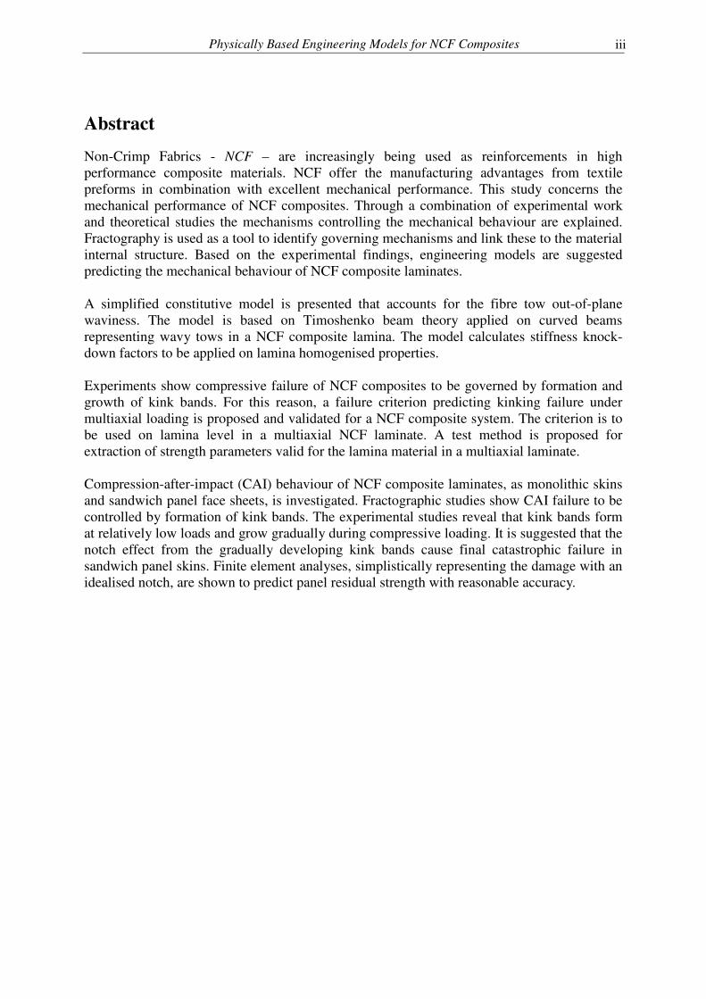
Abstract
Non-Crimp Fabrics - NCF – are increasingly being used as reinforcements in high performance composite materials. NCF offer the manufacturing advantages from textile preforms in combination with excellent mechanical performance. This study concerns the mechanical performance of NCF composites. Through a combination of experimental work and theoretical studies the mechanisms controlling the mechanical behaviour are explained. Fractography is used as a tool to identify governing mechanisms and link these to the material internal structure. Based on the experimental findings, engineering models are suggested predicting the mechanical behaviour of NCF composite laminates. A simplified constitutive model is presented that accounts for the fibre tow out-of-plane waviness. The model is based on Timoshenko beam theory applied on curved beams representing wavy tows in a NCF composite lamina. The model calculates stiffness knock-down factors to be applied on lamina homogenised properties. Experiments show compressive failure of NCF composites to be governed by formation and growth of kink bands. For this reason, a failure criterion predicting kinking failure under multiaxial loading is proposed and validated for a NCF composite system. The criterion is to be used on lamina level in a multiaxial NCF laminate. A test method is proposed for extraction of strength parameters valid for the lamina material in a multiaxial laminate. Compression-after-impact (CAI) behaviour of NCF composite laminates, as monolithic skins and sandwich panel face sheets, is investigated. Fractographic studies show CAI failure to be controlled by formation of kink bands. The experimental studies reveal that kink bands form at relatively low loads and grow gradually during compressive loading. It is suggested that the notch effect from the gradually developing kink bands cause final catastrophic failure in sandwich panel skins. Finite element analyses, simplistically representing the damage with an idealised notch, are shown to predict panel residual strength with reasonable accuracy.

Physically Based Engineering Models for NCF Composites
v
Dissertation
This thesis contains a brief introduction to the research area and the following appended papers: Paper A F. Edgren and L. E. Asp. Approximate Analytical Constitutive Model for Non-Crimp Fabric Composites. Composites Part A: applied science and manufacturing, Vol. 36, 2005. Paper B F. Edgren, L. E. Asp and R. Joffe, Failure of NCF Composites Subjected to Combined Compression and Shear Loading. Accepted for publication in Composites Science and Technology. Paper C F. Edgren, L. E. Asp and P. H. Bull. Compressive Failure of Impacted NCF Composite Sandwich Panels – Characterisation of the Failure Process. Journal of Composite Materials, Vol. 38, No. 6, 2004 Paper D F. Edgren, Compressive Failure NCF Composites. In: Proceedings of the American Society for Composites Twentieth Technical Conference, 2005, Drexel University, Philadelphia, USA. Paper E F. Edgren and L. E. Asp, Compression After Impact Strength of NCF Composite Sandwich Panels, To be submitted.

Physically Based Engineering Models for NCF Composites
vii
Division of work between authors
Paper A Edgren suggested the approach and performed the calculations. The authors jointly wrote the paper. Paper B Edgren and Joffe performed the mechanical tests. Edgren performed the fractography and the theoretical work. Edgren and Asp wrote the paper. Paper C Edgren, Bull and Asp jointly performed the mechanical tests. Edgren performed the fractography and wrote the paper. Asp proof-read the paper and contributed with suggestions and comments. Paper E Asp suggested the approach. Edgren performed the theoretical work and wrote the paper. Asp proof-read the paper and contributed with suggestions and comments.

Physically Based Engineering Models for NCF Composites
ix
Contents
Preface i Abstract iii Dissertation v Division of work between authors vii 1. Background 1 2. Non-Crimp fabric composites 4 2.1. Non-Crimp Fabrics 4 2.2. Manufacturing of NCF composites 7 2.3. Structure of NCF composite 7 3. Basic mechanical properties and theoretical treatment 9 3.1. Stiffness 10 3.2. Damage formation and failure mechanisms 11 3.2.1. Tension 11 3.2.2. Compression 12 4. Damage tolerance 15 4.1. Characteristics of impact damage 16 4.2. Compression after impact 18 5. Future work 22 6. References 23 Paper A A1-A18
Paper B B1-B26
Paper C C1-C22
Paper D D1-D16
Paper E E1-E19

Physically Based Engineering Models for NCF Composites
1
1. Background
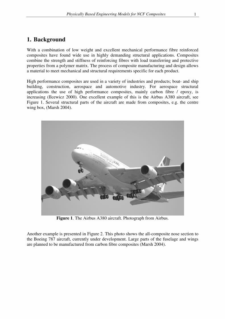
With a combination of low weight and excellent mechanical performance fibre reinforced composites have found wide use in highly demanding structural applications. Composites combine the strength and stiffness of reinforcing fibres with load transferring and protective properties from a polymer matrix. The process of composite manufacturing and design allows a material to meet mechanical and structural requirements specific for each product. High performance composites are used in a variety of industries and products; boat- and ship building, construction, aerospace and automotive industry. For aerospace structural applications the use of high performance composites, mainly carbon fibre / epoxy, is increasing (Ilcewicz 2000). One excellent example of this is the Airbus A380 aircraft, see Figure 1. Several structural parts of the aircraft are made from composites, e.g. the centre wing box, (Marsh 2004).
Figure 1. The Airbus A380 aircraft. Photograph from Airbus.
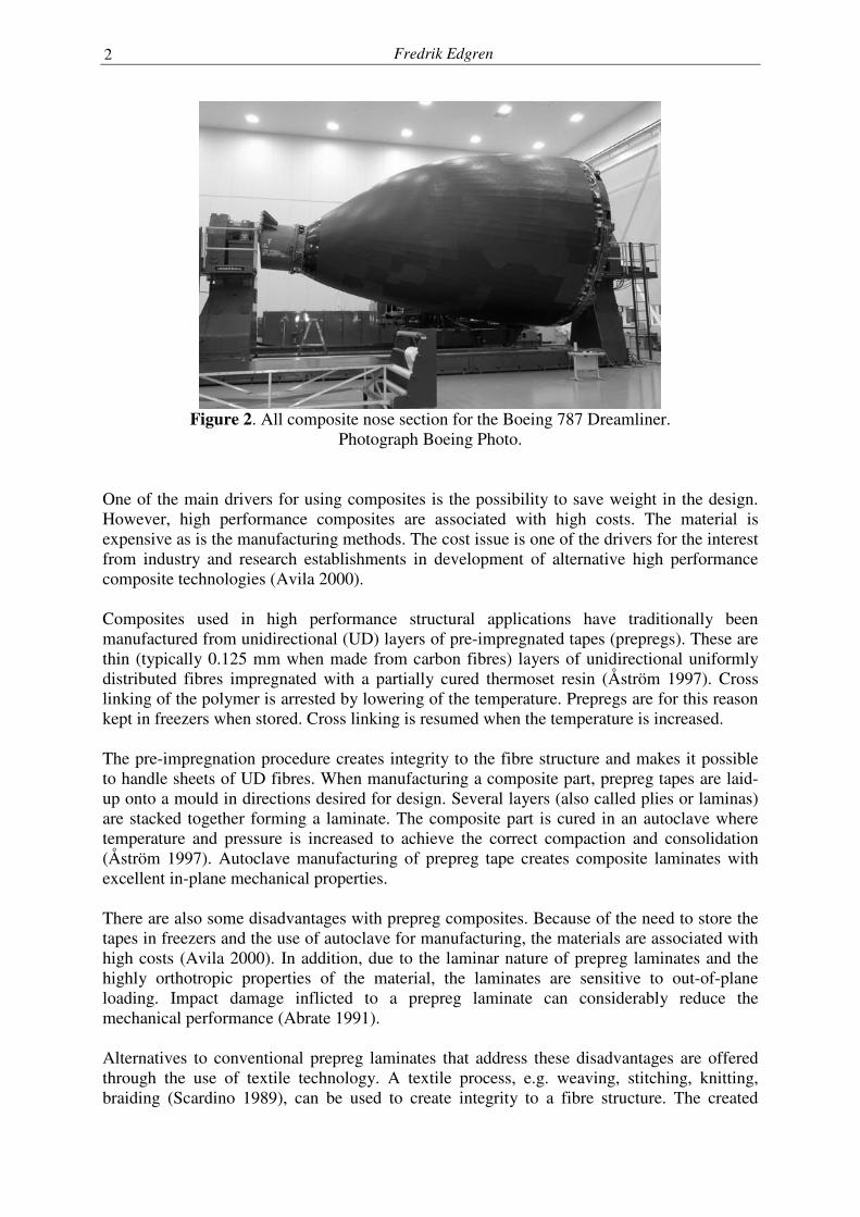
Another example is presented in Figure 2. This photo shows the all-composite nose section to the Boeing 787 aircraft, currently under development. Large parts of the fuselage and wings are planned to be manufactured from carbon fibre composites (Marsh 2004).
Fredrik Edgren
2
Figure 2. All composite nose section for the Boeing 787 Dreamliner.
Photograph Boeing Photo. One of the main drivers for using composites is the possibility to save weight in the design. However, high performance composites are associated with high costs. The material is expensive as is the manufacturing methods. The cost issue is one of the drivers for the interest from industry and research establishments in development of alternative high performance composite technologies (Avila 2000). Composites used in high performance structural applications have traditionally been manufactured from unidirectional (UD) layers of pre-impregnated tapes (prepregs). These are thin (typically 0.125 mm when made from carbon fibres) layers of unidirectional uniformly distributed fibres impregnated with a partially cured thermoset resin (Åström 1997). Cross linking of the polymer is arrested by lowering of the temperature. Prepregs are for this reason kept in freezers when stored. Cross linking is resumed when the temperature is increased. The pre-impregnation procedure creates integrity to the fibre structure and makes it possible to handle sheets of UD fibres. When manufacturing a composite part, prepreg tapes are laid-up onto a mould in directions desired for design. Several layers (also called plies or laminas) are stacked together forming a laminate. The composite part is cured in an autoclave where temperature and pressure is increased to achieve the correct compaction and consolidation (Åström 1997). Autoclave manufacturing of prepreg tape creates composite laminates with excellent in-plane mechanical properties. There are also some disadvantages with prepreg composites. Because of the need to store the tapes in freezers and the use of autoclave for manufacturing, the materials are associated with high costs (Avila 2000). In addition, due to the laminar nature of prepreg laminates and the highly orthotropic properties of the material, the laminates are sensitive to out-of-plane loading. Impact damage inflicted to a prepreg laminate can considerably reduce the mechanical performance (Abrate 1991). Alternatives to conventional prepreg laminates that address these disadvantages are offered through the use of textile technology. A textile process, e.g. weaving, stitching, knitting, braiding (Scardino 1989), can be used to create integrity to a fibre structure. The created
Physically Based Engineering Models for NCF Composites
3
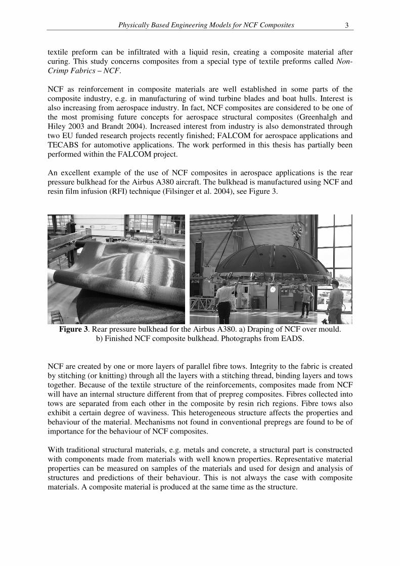
textile preform can be infiltrated with a liquid resin, creating a composite material after curing. This study concerns composites from a special type of textile preforms called Non-Crimp Fabrics – NCF. NCF as reinforcement in composite materials are well established in some parts of the composite industry, e.g. in manufacturing of wind turbine blades and boat hulls. Interest is also increasing from aerospace industry. In fact, NCF composites are considered to be one of the most promising future concepts for aerospace structural composites (Greenhalgh and Hiley 2003 and Brandt 2004). Increased interest from industry is also demonstrated through two EU funded research projects recently finished; FALCOM for aerospace applications and TECABS for automotive applications. The work performed in this thesis has partially been performed within the FALCOM project. An excellent example of the use of NCF composites in aerospace applications is the rear pressure bulkhead for the Airbus A380 aircraft. The bulkhead is manufactured using NCF and resin film infusion (RFI) technique (Filsinger et al. 2004), see Figure 3.
Figure 3. Rear pressure bulkhead for the Airbus A380. a) Draping of NCF over mould.
b) Finished NCF composite bulkhead. Photographs from EADS. NCF are created by one or more layers of parallel fibre tows. Integrity to the fabric is created by stitching (or knitting) through all the layers with a stitching thread, binding layers and tows together. Because of the textile structure of the reinforcements, composites made from NCF will have an internal structure different from that of prepreg composites. Fibres collected into tows are separated from each other in the composite by resin rich regions. Fibre tows also exhibit a certain degree of waviness. This heterogeneous structure affects the properties and behaviour of the material. Mechanisms not found in conventional prepregs are found to be of importance for the behaviour of NCF composites. With traditional structural materials, e.g. metals and concrete, a structural part is constructed with components made from materials with well known properties. Representative material properties can be measured on samples of the materials and used for design and analysis of structures and predictions of their behaviour. This is not always the case with composite materials. A composite material is produced at the same time as the structure.
Fredrik Edgren
4
Depending on the shape of the final composite structure and the need for strength and stiffness in different parts and directions, fibres are spread out in several layers and in different directions following the shape of the mould. Because of this, the amount and the shape of fibres will vary over the structure. Since the composite material properties depend on the amount and distribution of fibres, different parts of a structure will have different material properties. This possibility to tailor a material through adaptation of the fibre architecture to the structural needs is a great advantage that comes with composite materials. However, it also brings some practical engineering problems, especially for textile composites. The mechanical performance of the composite material is strongly linked to the manufacturing process. Predictions and simulations of the composite mechanical behaviour need to consider also the manufacturing of the material. During the work presented in this thesis focus has been on understanding the mechanisms relevant for NCF composites performance. The ambition has also been to develop engineering methods for modelling of NCF composites. Special attention has been paid to impact damage tolerance and mechanisms governing residual compressive strength. A recent report (Brandt 2004) highlights the need for composite design models to be developed in a form accessible to engineers. Input data needed for models must be possible to determine with reasonable effort and without requirements of specialist knowledge in e.g. processing. This view has also been the guideline throughout the work presented in this thesis. Models suggested should, perhaps after some further development, be in a form applicable for engineers and designers. It is the authors view that a simple and easy-to-use model, perhaps in need of additional refinement, is more likely to be of practical use and further developed than a too complicated model in need of simplifications. This thesis consists of an introduction to the area of NCF composites and five appended papers. In the introduction the material and the basic mechanical properties are described and discussed. The contents and conclusions from the appended papers are briefly discussed and an attempt is made to put the results into a larger context. The introduction ends with some ideas and suggestions for future research
2. Non-Crimp fabric composites
2.1. Non-Crimp Fabrics
Textile structures have been used as reinforcements in composite materials for many years. A widely used structure is the weave. A woven fabric gains integrity from the interlacing of warp (yarn in the longitudinal direction of production) and weft (yarn in the transverse direction) yarn systems (Scardino 1989, Byun and Chou 2000). The interlacing warp/weft structure induces crimp in the yarns which has a negative effect on composite laminate in-plane mechanical properties (stiffness and strength) (Bishop 1989). Non-crimp fabrics offer the advantages from the textiles to the composite material with a reduction of the disadvantages from the yarn crimp in woven fabrics. NCF have a structure where one or several yarn systems are held together by a binding yarn system. The interlacing yarn structure characterising woven fabrics is not found in NCF.
Physically Based Engineering Models for NCF Composites
5
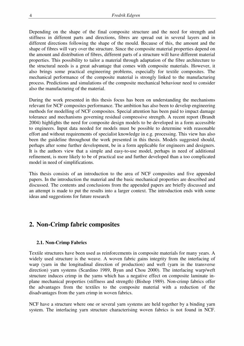
Instead, one or more layers of fibre tows are stacked on top of each other and held together by the binding yarn system, see schematic in Figure 4. Each layer consists of parallel fibre tows. Several layers are stacked in different directions to create the desired fabric properties.
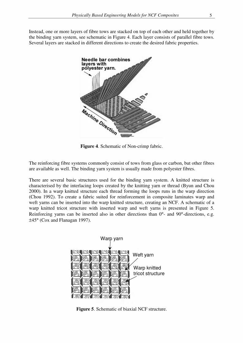
Figure 4. Schematic of Non-crimp fabric. The reinforcing fibre systems commonly consist of tows from glass or carbon, but other fibres are available as well. The binding yarn system is usually made from polyester fibres. There are several basic structures used for the binding yarn system. A knitted structure is characterised by the interlacing loops created by the knitting yarn or thread (Byun and Chou 2000). In a warp knitted structure each thread forming the loops runs in the warp direction (Chou 1992). To create a fabric suited for reinforcement in composite laminates warp and weft yarns can be inserted into the warp knitted structure, creating an NCF. A schematic of a warp knitted tricot structure with inserted warp and weft yarns is presented in Figure 5. Reinforcing yarns can be inserted also in other directions than 0°- and 90°-directions, e.g. ±45° (Cox and Flanagan 1997).
Warp yarn
Weft yarn
Warp knitted tricot structure
Figure 5. Schematic of biaxial NCF structure.
Fredrik Edgren
6
Another commonly used binder yarn structure is achieved through the stitching process. For NCF in structural applications it is mainly the modified lock stitch and chain stitch that are of interest (Cox and Flanagan 1997). There are thus several different methods to manufacture the type of textile preforms investigated in this study. Consequently, there are several different names available for the fabrics. In the textile community they are sometimes referred to as DOS - Directionally Oriented Structures (Dartman 2002). Other more or less commonly used names are Stitchbonded fabrics, multiaxial multiply fabrics (MMFs), multiaxial warp-knits and weft and/or warp inserted warp knitted structures. A recent European standard (EN 13473 2001) defines the terminology used in description of the fabrics. It is possible to find technical differences, from a textile point-of-view, between some of these fabrics. However, from a composite materials performance point-of-view there is no principal difference between composites from NCF with different binder yarn structures (Asp et al. 2004). The binding yarn system creates integrity to the dry reinforcement during handling of the preforms. It is however likely that different binding systems create different drapeability and in that sense affect the composite material structure in different ways (Lomov et al. 2002). The work on stitchbonded fabrics started with the development of the Malimo stitchbonding system in the 1950s (Mansfield 2002). The main use of the fabrics was as substrates for coated fabrics (flexible composites) (Hu et al. 1998). The fabrics were first used for composite materials in the boat building industry (Steggal 1999, Bibo et al. 1997). NCF are often characterised through the number of reinforcement yarn directions inserted into the binding structure. Biaxial, triaxial and quadriaxial fabrics are the most common fabrics commercially available. It is also common to give information on the surface weight of reinforcing fibres in each direction. These weights can then, together with a known fibre density, be transformed into fibre volume fraction if the ply thickness are known. One important thing to notice when using NCF reinforcements is the lack of symmetry that comes with using a multiaxial fabric other than 0°/90°. A +θ offaxis ply in an NCF translates into a -θ ply when the fabric is turned upside down. A symmetric laminate lay-up thus requires use of two different NCF configurations, one for each side of the laminate mid-plane. Despite the name - Non-crimp - a certain amount of fibre crimp is present in the fabric and in the final composite. Backer (1966) defines yarn crimp as the relative difference in length between the yarn and the fabric:
f
fy
l
llC
−= (1)
where: C is the yarn crimp, ly is the length of the yarn in the fabric and lf is the length of the fabric. However, waviness of fibre tows in the composite comes from several sources. In addition to the tow crimp in equation (1), fibre waviness is also induced by the composite manufacturing
Physically Based Engineering Models for NCF Composites
7
process. This is discussed in following sections. As will be seen, the effects of fibre crimp can not be overlooked and crimp is an important factor to consider when predicting composite elastic performance and failure mechanisms.
2.2. Manufacturing of NCF composites
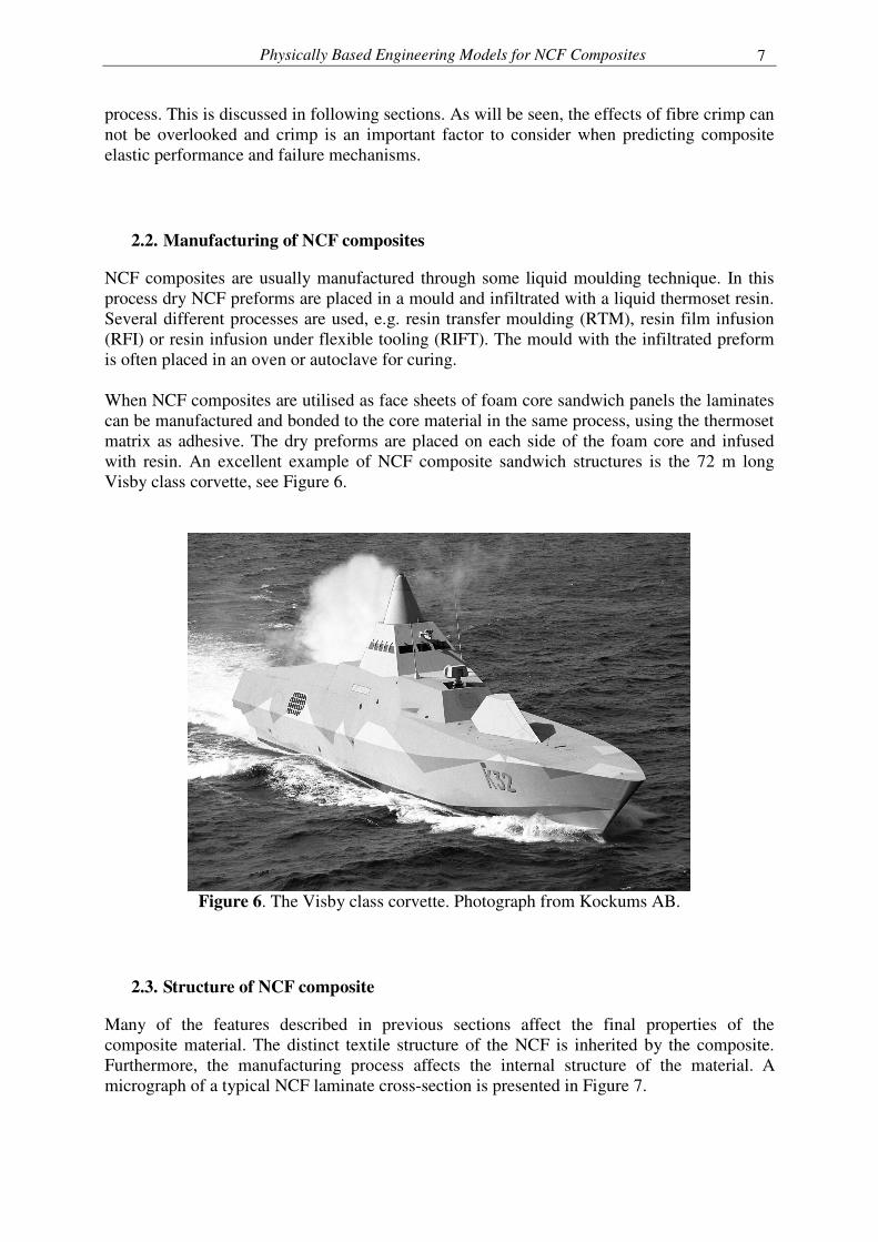
NCF composites are usually manufactured through some liquid moulding technique. In this process dry NCF preforms are placed in a mould and infiltrated with a liquid thermoset resin. Several different processes are used, e.g. resin transfer moulding (RTM), resin film infusion (RFI) or resin infusion under flexible tooling (RIFT). The mould with the infiltrated preform is often placed in an oven or autoclave for curing. When NCF composites are utilised as face sheets of foam core sandwich panels the laminates can be manufactured and bonded to the core material in the same process, using the thermoset matrix as adhesive. The dry preforms are placed on each side of the foam core and infused with resin. An excellent example of NCF composite sandwich structures is the 72 m long Visby class corvette, see Figure 6.
Figure 6. The Visby class corvette. Photograph from Kockums AB.
2.3. Structure of NCF composite
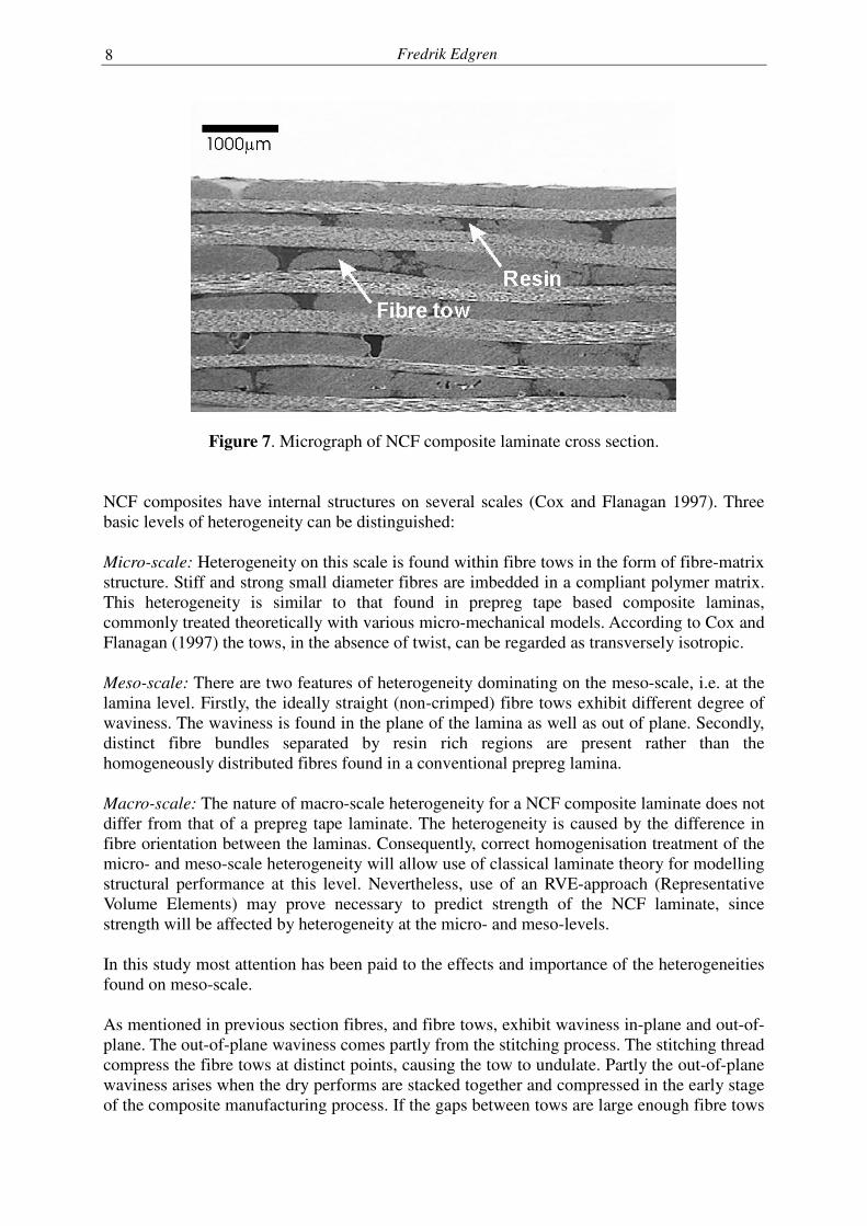
Many of the features described in previous sections affect the final properties of the composite material. The distinct textile structure of the NCF is inherited by the composite. Furthermore, the manufacturing process affects the internal structure of the material. A micrograph of a typical NCF laminate cross-section is presented in Figure 7.
Fredrik Edgren
8
Figure 7. Micrograph of NCF composite laminate cross section.
NCF composites have internal structures on several scales (Cox and Flanagan 1997). Three basic levels of heterogeneity can be distinguished: Micro-scale: Heterogeneity on this scale is found within fibre tows in the form of fibre-matrix structure. Stiff and strong small diameter fibres are imbedded in a compliant polymer matrix. This heterogeneity is similar to that found in prepreg tape based composite laminas, commonly treated theoretically with various micro-mechanical models. According to Cox and Flanagan (1997) the tows, in the absence of twist, can be regarded as transversely isotropic. Meso-scale: There are two features of heterogeneity dominating on the meso-scale, i.e. at the lamina level. Firstly, the ideally straight (non-crimped) fibre tows exhibit different degree of waviness. The waviness is found in the plane of the lamina as well as out of plane. Secondly, distinct fibre bundles separated by resin rich regions are present rather than the homogeneously distributed fibres found in a conventional prepreg lamina. Macro-scale: The nature of macro-scale heterogeneity for a NCF composite laminate does not differ from that of a prepreg tape laminate. The heterogeneity is caused by the difference in fibre orientation between the laminas. Consequently, correct homogenisation treatment of the micro- and meso-scale heterogeneity will allow use of classical laminate theory for modelling structural performance at this level. Nevertheless, use of an RVE-approach (Representative Volume Elements) may prove necessary to predict strength of the NCF laminate, since strength will be affected by heterogeneity at the micro- and meso-levels. In this study most attention has been paid to the effects and importance of the heterogeneities found on meso-scale. As mentioned in previous section fibres, and fibre tows, exhibit waviness in-plane and out-of-plane. The out-of-plane waviness comes partly from the stitching process. The stitching thread compress the fibre tows at distinct points, causing the tow to undulate. Partly the out-of-plane waviness arises when the dry performs are stacked together and compressed in the early stage of the composite manufacturing process. If the gaps between tows are large enough fibre tows
Physically Based Engineering Models for NCF Composites
9
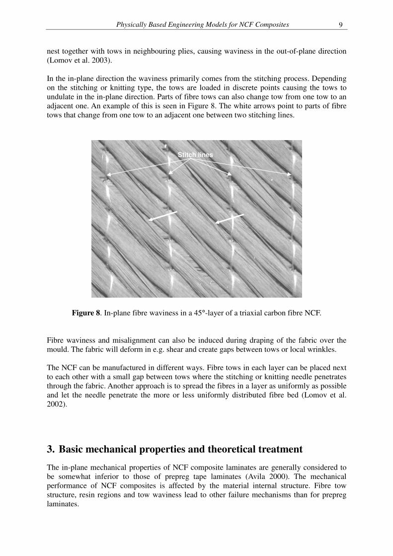
nest together with tows in neighbouring plies, causing waviness in the out-of-plane direction (Lomov et al. 2003). In the in-plane direction the waviness primarily comes from the stitching process. Depending on the stitching or knitting type, the tows are loaded in discrete points causing the tows to undulate in the in-plane direction. Parts of fibre tows can also change tow from one tow to an adjacent one. An example of this is seen in Figure 8. The white arrows point to parts of fibre tows that change from one tow to an adjacent one between two stitching lines.
Stitch lines
Figure 8. In-plane fibre waviness in a 45°-layer of a triaxial carbon fibre NCF. Fibre waviness and misalignment can also be induced during draping of the fabric over the mould. The fabric will deform in e.g. shear and create gaps between tows or local wrinkles. The NCF can be manufactured in different ways. Fibre tows in each layer can be placed next to each other with a small gap between tows where the stitching or knitting needle penetrates through the fabric. Another approach is to spread the fibres in a layer as uniformly as possible and let the needle penetrate the more or less uniformly distributed fibre bed (Lomov et al. 2002).
3. Basic mechanical properties and theoretical treatment
The in-plane mechanical properties of NCF composite laminates are generally considered to be somewhat inferior to those of prepreg tape laminates (Avila 2000). The mechanical performance of NCF composites is affected by the material internal structure. Fibre tow structure, resin regions and tow waviness lead to other failure mechanisms than for prepreg laminates.
Fredrik Edgren
10
This section concerns some features of the basic mechanical properties. The influence from the material meso-scale structure is discussed and the effects on material elastic properties and failure mechanisms.
3.1. Stiffness
Fibre misalignment reduces longitudinal stiffness of unidirectional fibre composites (Piggott 1995). Several authors (Bibo et al. 1997, Truong et al. 2005) report experimentally measured values of tensile or compressive modulus being lower than the theoretical value, assuming straight fibres, for NCF composites. Some of these effects are attributed to errors in fibre orientation (deviations from theoretical directions) due to handling of the preforms during lay-up and from precision in cutting of specimens. However, some of the stiffness reduction has its origin in the meso-scale heterogeneity, in the form of fibre waviness, caused by manufacturing of the NCF and NCF composite. The effects of fibre waviness thus need to be considered in the constitutive modelling of the material. From the literature it is possible to distinguish two main approaches. The first one utilises two- or three-dimensional FE-models of unit cells describing the NCF composite architecture. In these models the meso-scale heterogeneities (fibre tows, resin pockets, tow waviness, stitch yarn) are modelled with different degree of detail. Drapier and Wisnom (1999a, 1999b) used a two-dimensional FE-model to describe a repeating unit cell for simulation of compression and shear behaviour of a NCF cross-ply laminate. A similar approach was used by Paris et al. (2004), who used a three-dimensional FE-model of a NCF composite as a representative volume element (RVE). In both of the mentioned cases the meso-scale architecture of the material has been modelled in fair detail. The major benefit using this approach is the possibility to also predict material strength and study the mechanisms governing failure, as demonstrated by Drapier and Wisnom (1999a, 1999b) and Paris et al. (2004). From an engineering point-of-view, however, this approach also suffers some drawbacks. Firstly, the analyses can be complicated and time consuming. This approach does not offer a rapid method for performance prediction of NCF composites. Secondly, this approach requires the material to be characterised on the meso-scale. Explicitly modelling the fibre tows requires material data for the material within the tows and detailed information, or assumptions, on tow geometry. These data can be difficult to retrieve and the testing required goes beyond conventional standard testing. The other main approach allows use of equivalent single layer theories, e.g. CLT, for prediction of laminate response. The structure of the NCF composite, with distinct separate layers of fibres in different directions, makes the use of CLT a natural choice. This requires however an approach of how to consider the fibre tow crimp and the stiffness reducing effect thereof. For this purpose there are several models considering fibre tow waviness or fibre distortions. Klopp et al. (2003) presented a model that reduces the volume fraction of fibres with respect to an in-plane ‘fraction of fibre displacement’ caused by the stitching yarn. The resulting reduced fibre volume fractions are used in CLT to predict stiffness properties of the laminate. Cox and Dadkhah (1995) and Cox and Flanagan (1997) developed stiffness models for three-dimensional weave composites, with rather high waviness. Cox and co-workers employed an orientation-averaging model to determine knock-down factors of the wavy composite layers. The model considers the off-axis angle to reduce the stiffness of the wavy
Physically Based Engineering Models for NCF Composites
11
ply. Lee and Harris (1990) proposed a more sophisticated model. Their mathematical model was based on the Euler-Bernoulli beam theory for beams on an elastic foundation, predicting the effective Young’s modulus of piecewise isotropic composite laminates with local ply curvature in the main load-carrying layers. A stiffness reduction model inspired by Lee and Harris (1990) is presented in Paper A of this thesis. The mathematical model is based on Timoshenko beam theory applied on curved beams, representing wavy tows in a NCF composite layer. The model calculates a knock-down factor used to reduce the longitudinal modulus of the ply material in the laminate. Comparison between experimental data for NCF composites and predictions using the model presented in Paper A and the model by Cox and Dadkhah (1995) showed that the curved Timoshenko beam model provides accurate predications whereas the model considering waviness as an off-axis angle produces too compliant predictions of laminate stiffness. In the study presented in Paper A only the out-of-plane fibre tow waviness has been considered. The fibre tows are assumed to have a sinusoidal shape, characterised by a wavelength, λ, and amplitude, A. The wavelength is linked to the geometry of the preform through the distance between two adjacent stitch lines (also called the stitch gauge). The amplitude of the assumed sine wave is not linked to the preform geometry. Since the out-of-plane waviness to a large extent is created via nesting of tows into adjacent layers during composite manufacturing, it is not possible to decide a value for the amplitude based on information on the preform geometry only. In Paper A, the amplitude was estimated from statistical treatments of measurements of tow locations in the laminates tested, see (Drapier and Wisnom 1999a). From an engineering perspective this is not an ideal approach. There are, however, still no links established between the preform geometry, via processing models predicting the additional fibre tow distortion, and the meso-scale structure of the final composite.
3.2. Damage formation and failure mechanisms
The heterogeneous meso-scale structure of NCF composites affects the formation of damage and failure mechanisms in the material. As already mentioned, fibre tow waviness affects the material stiffness. In addition, failure mechanisms in NCF composites may generally be linked to fibre tow crimp. This section briefly reviews the tensile and compressive behaviour typically found in NCF composites.
3.2.1. Tension NCF composite tensile strength is reported generally being lower than for corresponding prepreg laminates (Bibo et al. 1997, Dexter and Hasko 1996). The slightly lower tensile strength can partly be explained by the heterogeneous meso-scale structure. Fibre waviness and tow structure cause stress concentrations leading to premature failure. Other possible reasons are fractured fibres from the stitching process and fibre misalignments caused by handling of preforms during lay-up.
Fredrik Edgren
12
Tensile strength of multi-axial laminates is a fibre dominated property (Purslow 1981). Specimen failure will occur when a sufficient amount of fibres have failed. However, other failure mechanisms will be present as well. In conventional prepreg cross-ply laminates the first damage to form is transverse cracks in the 90°-plies (Purslow 1981). During increase of tensile load more cracks will form causing reduction of laminate stiffness and non-linear overall response. Each transverse crack extend through the entire thickness of the 90°-layer (even if several 90°-plies are stacked together) with the plane of the crack normal to the laminate midplane. The average crack opening displacement (COD) has been shown to govern the change of laminate stiffness (Joffe et al. 2001, Varna 2001). In NCF composite cross-ply laminates the appearance of transverse cracks in uniaxial tension is more complicated. This is demonstrated in a paper by Edgren et al. (2004) where cross-ply [0°/90°]s NCF composite laminates were tested in uniaxial tension. As for prepreg laminates transverse cracks were found to form in the 90°-plies as the first damage mechanism. Cracks were found to form mainly within fibre tows, rather than in between tows. Moreover, cracks did not generally extend through the two 90°-plies. Instead, cracks were usually contained within single fibre tows, thus limiting the COD. Cracks in the 90°-tows were also found to propagate in the direction of the load. The occurrence of these longitudinal cracks was explained by FE-analyses using a RVE approach. The analyses revealed that high out-of-plane normal stresses formed in the 90°-tows due to the waviness of the 0°-tows. When the cross-ply is loaded the 0°-tows straighten out causing out-of-plane stresses in the 90°-tows.
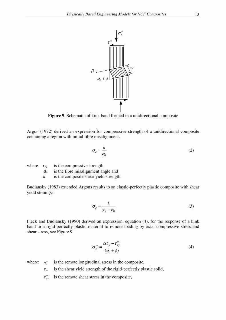
3.2.2. Compression Compressive strength of NCF composites has been reported being as low as half of that in tension (Asp et al. 2004). The main reason for this is the heterogeneous meso-scale structure, especially fibre tow waviness, of NCF laminates. The dominating mechanism of compressive failure in composite laminates is plastic fibre microbuckling (Fleck 1997). This mechanism is a plastic shear instability where initially misaligned fibres cause shear strains to localise in a small region. Fibres fail into small segments which rotate under increasing load. The fibre segments form a band, called kink band, with fibre segments rotated an angle (φ0+φ) from the main fibre direction. The kink band grows at an angle β to the fibre direction. A schematic of a kink band in a unidirectional composite is presented in Figure 9.
Physically Based Engineering Models for NCF Composites
13
∞xσ
φφ +0
β
∞τ
w
Figure 9. Schematic of kink band formed in a unidirectional composite
Argon (1972) derived an expression for compressive strength of a unidirectional composite containing a region with initial fibre misalignment.
0φ
σ kc = (2)
where σc is the compressive strength, φ0 is the fibre misalignment angle and k is the composite shear yield strength. Budiansky (1983) extended Argons results to an elastic-perfectly plastic composite with shear yield strain γY:
0φγ
σ+
=Y
ck
(3)
Fleck and Budiansky (1990) derived an expression, equation (4), for the response of a kink band in a rigid-perfectly plastic material to remote loading by axial compressive stress and shear stress, see Figure 9.
)( 0 φφ
τατσ
+−
=∞
∞ xyyx (4)
where: ∞
xσ is the remote longitudinal stress in the composite,
yτ is the shear yield strength of the rigid-perfectly plastic solid,
∞xyτ is the remote shear stress in the composite,
Fredrik Edgren
14
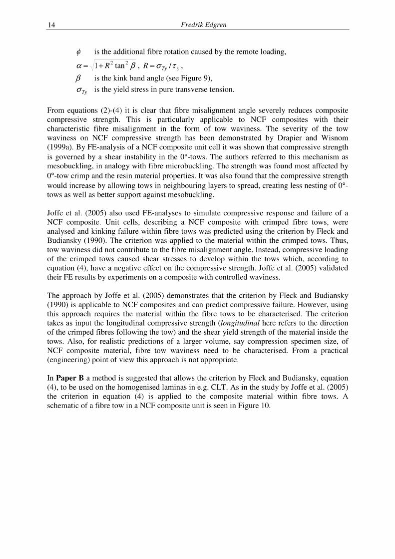
φ is the additional fibre rotation caused by the remote loading,
βα 22 tan1 R+= , yTyR τσ /= ,
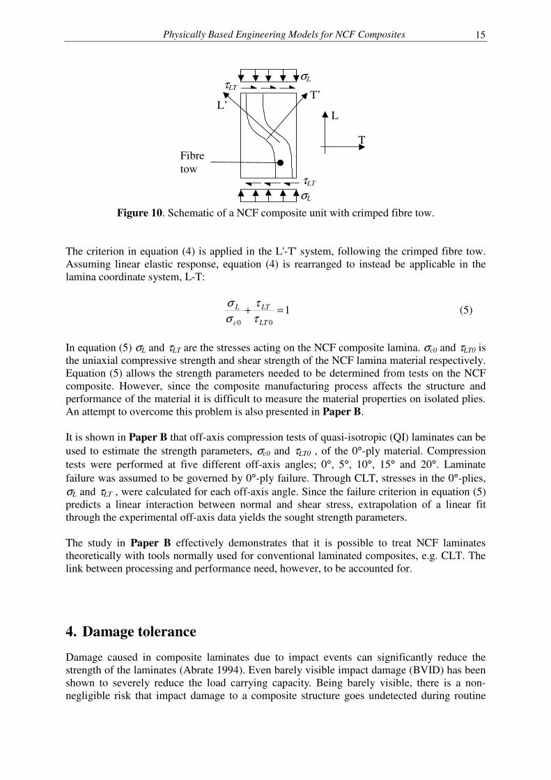
β is the kink band angle (see Figure 9), Tyσ is the yield stress in pure transverse tension. From equations (2)-(4) it is clear that fibre misalignment angle severely reduces composite compressive strength. This is particularly applicable to NCF composites with their characteristic fibre misalignment in the form of tow waviness. The severity of the tow waviness on NCF compressive strength has been demonstrated by Drapier and Wisnom (1999a). By FE-analysis of a NCF composite unit cell it was shown that compressive strength is governed by a shear instability in the 0°-tows. The authors referred to this mechanism as mesobuckling, in analogy with fibre microbuckling. The strength was found most affected by 0°-tow crimp and the resin material properties. It was also found that the compressive strength would increase by allowing tows in neighbouring layers to spread, creating less nesting of 0°-tows as well as better support against mesobuckling. Joffe et al. (2005) also used FE-analyses to simulate compressive response and failure of a NCF composite. Unit cells, describing a NCF composite with crimped fibre tows, were analysed and kinking failure within fibre tows was predicted using the criterion by Fleck and Budiansky (1990). The criterion was applied to the material within the crimped tows. Thus, tow waviness did not contribute to the fibre misalignment angle. Instead, compressive loading of the crimped tows caused shear stresses to develop within the tows which, according to equation (4), have a negative effect on the compressive strength. Joffe et al. (2005) validated their FE results by experiments on a composite with controlled waviness. The approach by Joffe et al. (2005) demonstrates that the criterion by Fleck and Budiansky (1990) is applicable to NCF composites and can predict compressive failure. However, using this approach requires the material within the fibre tows to be characterised. The criterion takes as input the longitudinal compressive strength (longitudinal here refers to the direction of the crimped fibres following the tow) and the shear yield strength of the material inside the tows. Also, for realistic predictions of a larger volume, say compression specimen size, of NCF composite material, fibre tow waviness need to be characterised. From a practical (engineering) point of view this approach is not appropriate. In Paper B a method is suggested that allows the criterion by Fleck and Budiansky, equation (4), to be used on the homogenised laminas in e.g. CLT. As in the study by Joffe et al. (2005) the criterion in equation (4) is applied to the composite material within fibre tows. A schematic of a fibre tow in a NCF composite unit is seen in Figure 10.
Physically Based Engineering Models for NCF Composites
15
T
L
T’ L’
Fibre tow
σL
σL τLT
τLT
Figure 10. Schematic of a NCF composite unit with crimped fibre tow.
The criterion in equation (4) is applied in the L'-T' system, following the crimped fibre tow. Assuming linear elastic response, equation (4) is rearranged to instead be applicable in the lamina coordinate system, L-T:
100
=+LT
LT
c
L
ττ
σσ
(5)
In equation (5) σL and τLT are the stresses acting on the NCF composite lamina. σc0 and τLT0 is the uniaxial compressive strength and shear strength of the NCF lamina material respectively. Equation (5) allows the strength parameters needed to be determined from tests on the NCF composite. However, since the composite manufacturing process affects the structure and performance of the material it is difficult to measure the material properties on isolated plies. An attempt to overcome this problem is also presented in Paper B. It is shown in Paper B that off-axis compression tests of quasi-isotropic (QI) laminates can be used to estimate the strength parameters, σc0 and τLT0 , of the 0°-ply material. Compression tests were performed at five different off-axis angles; 0°, 5°, 10°, 15° and 20°. Laminate failure was assumed to be governed by 0°-ply failure. Through CLT, stresses in the 0°-plies, σL and τLT , were calculated for each off-axis angle. Since the failure criterion in equation (5) predicts a linear interaction between normal and shear stress, extrapolation of a linear fit through the experimental off-axis data yields the sought strength parameters. The study in Paper B effectively demonstrates that it is possible to treat NCF laminates theoretically with tools normally used for conventional laminated composites, e.g. CLT. The link between processing and performance need, however, to be accounted for.
4. Damage tolerance
Damage caused in composite laminates due to impact events can significantly reduce the strength of the laminates (Abrate 1994). Even barely visible impact damage (BVID) has been shown to severely reduce the load carrying capacity. Being barely visible, there is a non-negligible risk that impact damage to a composite structure goes undetected during routine
Fredrik Edgren
16
inspections. The risk of having a structure operating with an undetected damage, severely reducing its capacities, makes it necessary to consider the presence of the damage already at design stage. Models predicting the damage tolerance (the ability of the structure to perform with damage) and residual strengths need to be developed. Because of this, damage tolerance, in general, and compression after impact (CAI) behaviour in particular has gained much attention especially from the aircraft industry and in research associated with it. Damage tolerance of prepreg tape laminates has been studied extensively the last decades. Models successfully predicting e.g. CAI strength of prepreg laminates have been developed (Pavier and Clarke 1996, Soutis and Curtis 1996). Even though the basic mechanical properties (e.g. tensile and compressive strength) are somewhat lower for NCF composites than for conventional laminates, there is a possibility that engineering design properties, e.g. CAI strength, are improved. For NCF composites special expectations are made because of the stitched structure. Since delamination growth has been shown to govern CAI failure of prepreg laminates (Asp et al. 2001), expectations are made upon NCF laminates to be more damage tolerant. The binding yarn system, in the form of a stitching thread, have the potential to increase the delamination toughness, thus limiting the extent of delaminations caused by impact and also increasing the resistance to growth during CAI loading (Dransfield et al. 1994). Not only may the stitch thread increase delamination toughness, its presence will also hamper delaminations to open (delamination buckling). This further suppresses delamination growth (Nilsson et al. 2001). This section treats impact damage in NCF laminates and mechanisms governing residual compressive strength.
4.1. Characteristics of impact damage
The elastic response of an impacted plate is governed by the impactor versus plate mass ratio (Olsson 2000). For small mass ratios the plate response is dominated by flexural waves (or through-thickness waves for very small ratios). For larger ratios the response is quasi-static (Olsson 2006). It is however common to classify impact in terms of impact velocity (high velocity or low velocity impact). In the aircraft industry it is also customary to quantify the impact threat by the impact energy (Olsson 2006). Furthermore, a commonly used impact damage definition in the aircraft industry is the barely visible impact damage, BVID. In the European standard EN 6038 (1995) a BVID is defined as the damage caused by an impact leaving a 0.3 mm remaining dent on the surface of the laminate. The work performed on impact to laminated composites in this thesis is limited to large mass ratios, where the plate response can be considered quasi-static. Damage in composite laminates caused by impacts has been studied extensively. Excellent reviews on the subject can be found in two papers by Abrate (1991, 1994). The major part of the work published concerns impact to prepreg tape laminates. Studies have also been performed on impact damage in textile composites, whereof some concerns NCF laminates. Impact induced damage in composite laminates consists of fibre breakage, matrix cracks and delaminations (Abrate 1994). Laminates used as face sheets of sandwich structures are also likely to have a residual dent remaining on the impacted laminate surface (Olsson 1995).
Physically Based Engineering Models for NCF Composites
17
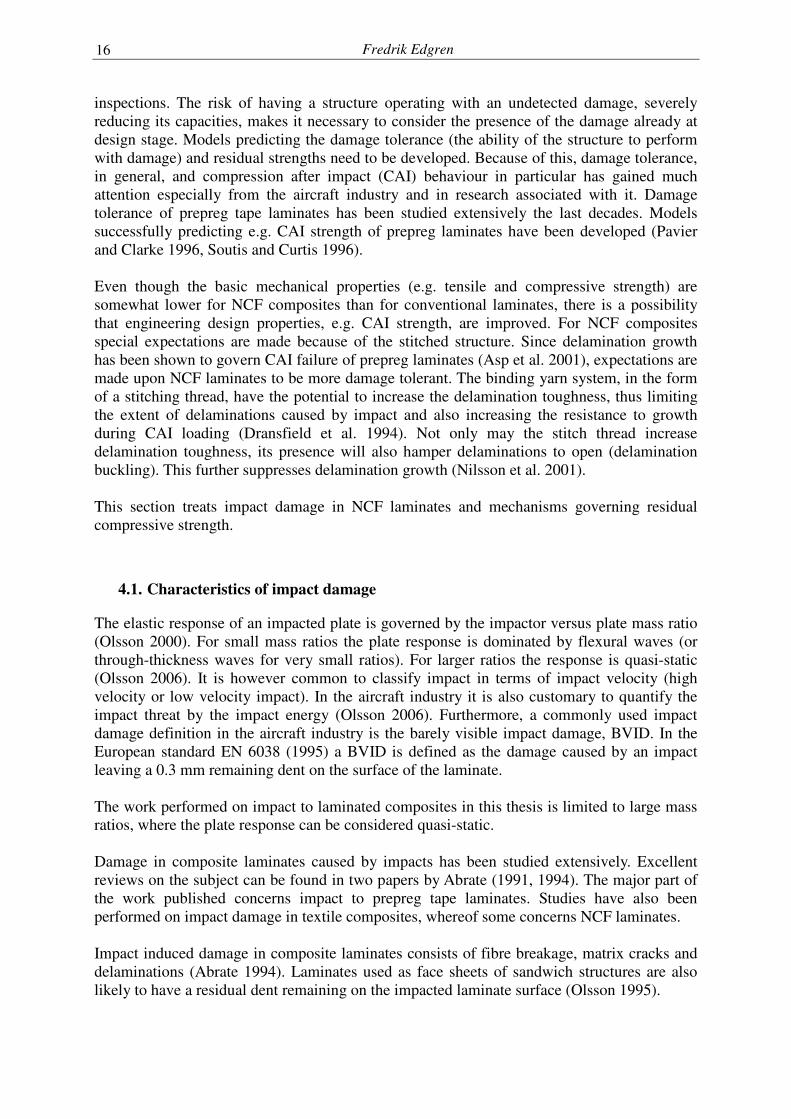
The work published on characterisation of impact damage in NCF composites is limited. Bibo and Hogg (1998) compared impact damage in NCF laminates with impact damage in prepreg tape laminates. Fracture mechanisms in NCF laminates manufactured with infusion techniques were found to be more complex, with the reinforcement architecture having a clear role in the development of cracks. Generally the delamination extent in the NCF laminates was smaller than in the tape based laminates. The authors also noted that the NCF meso structure, with distinct fibre tows and tow nesting, forces a delamination or crack front to grow along a more complicated path and through this inhibiting propagation of fracture. This paper also demonstrates the important link between the manufacturing process and the performance of the NCF composite. Infused NCF laminates were compared with prepregged NCF laminates. The prepregged NCF composite resulted in a structure resembling the prepreg tape laminates, with fibre tows more elongated and with a lower degree of tow nesting. This translated into a larger delamination extent compared to the infused laminates, which had a more heterogeneous meso structure. In Paper C and D of this thesis NCF laminates have been studied in compression after impact. Impact damage in the laminates were characterised by means of fractography. In all studied cases impact damage contained matrix cracks and delaminations. In the BVID cases little or no fibre fracture were noticed. From micrographs of polished sections taken through the impact damage it was found that delaminations typically ended with a matrix crack jumping down one or two plies, see Figure 11.
0°90°
45°-45°
-45°45°
90°0°
0°90°
45°-45°
-45°45°
90°0°
Impact point
90°-direction(mm)0 5 10 15 20-5-10-15-20
0°90°
90°
45°
45°
-45°-45°
0°
Figure 11. Damage in section through impacted (100J) NCF laminate, from Paper C.
It was also noted that delaminations preferably grow in interfaces where the difference in fibre direction is 90°. In the studied laminates this difference is only found in interfaces located within NCF blankets. This thus implies that the stitching thread did not manage to suppress the formation of delaminations. Generally the individual delaminations were found to have a rectangular shape. An example of this is seen in Figure 12. This figure shows ultrasonic C-scans of an impact damaged (100J) NCF laminate, [0°/90°/45°/-45°]s2, from the same material as used in the study presented in
Fredrik Edgren
18
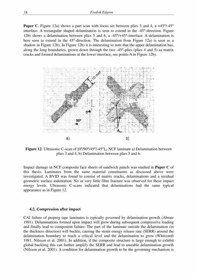
Paper C. Figure 12a) shows a part scan with focus set between plies 3 and 4, a +45°/-45° interface. A rectangular shaped delamination is seen to extend in the -45°-direction. Figure 12b) shows a delamination between plies 5 and 6, a -45°/+45°-interface. A delamination is here seen to extend in the 45°-direction. The delamination from Figure 12a) is seen as a shadow in Figure 12b). In Figure 12b) it is interesting to note that the upper delamination has, along the long boundaries, grown down through the two -45°-plies (plies 4 and 5) as matrix cracks and formed delaminations at the lower interface, see points A in Figure 12b).
Figure 12. Ultrasonic C-scan of [0°/90°/45°/-45°]s2 NCF laminate a) Delamination between
plies 3 and 4, b) Delamination between plies 5 and 6. Impact damage in NCF composite face sheets of sandwich panels was studied in Paper C of this thesis. Laminates from the same material constituents as discussed above were investigated. A BVID was found to consist of matrix cracks, delaminations and a residual geometric surface indentation. No or very little fibre fracture was observed for these impact energy levels. Ultrasonic C-scans indicated that delaminations had the same typical appearance as in Figure 12.
4.2. Compression after impact
CAI failure of prepreg tape laminates is typically governed by delamination growth (Abrate 1991). Delaminations formed upon impact will grow during subsequent compressive loading and finally lead to component failure. The part of the laminate outside the delamination (in the thickness direction) will buckle, causing the strain energy release rate (SERR) around the delamination boundary to reach a critical level and the delamination to grow (Whitcomb 1981, Nilsson et al. 2001). In addition, if the composite structure is large enough to exhibit global buckling this can further amplify the SERR and lead to unstable delamination growth (Nilsson et al. 2001). A condition for delamination growth to be the governing mechanism is
Physically Based Engineering Models for NCF Composites
19
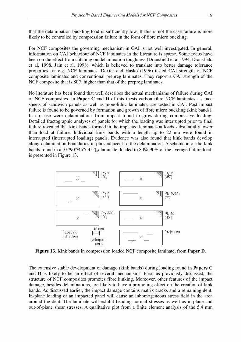
that the delamination buckling load is sufficiently low. If this is not the case failure is more likely to be controlled by compression failure in the form of fibre micro buckling. For NCF composites the governing mechanism in CAI is not well investigated. In general, information on CAI behaviour of NCF laminates in the literature is sparse. Some focus have been on the effect from stitching on delamination toughness (Dransfield et al 1994, Dransfield et al. 1998, Jain et al. 1998), which is believed to translate into better damage tolerance properties for e.g. NCF laminates. Dexter and Hasko (1996) tested CAI strength of NCF composite laminates and conventional prepreg laminates. They report a CAI strength of the NCF composite that is 80% higher than that of the prepreg laminates. No literature has been found that well describes the actual mechanisms of failure during CAI of NCF composites. In Paper C and D of this thesis carbon fibre NCF laminates, as face sheets of sandwich panels as well as monolithic laminates, are tested in CAI. Post impact failure is found to be governed by formation and growth of fibre micro buckling (kink bands). In no case were delaminations from impact found to grow during compressive loading. Detailed fractographic analyses of panels for which the loading was interrupted prior to final failure revealed that kink bands formed in the impacted laminates at loads substantially lower than load at failure. Individual kink bands with a length up to 22 mm were found in interrupted (interrupted loading) panels. Evidence was also found that kink bands develop along delamination boundaries in plies adjacent to the delamination. A schematic of the kink bands found in a [0°/90°/45°/-45°]s3 laminate, loaded to 80%-90% of the average failure load, is presented in Figure 13.
Figure 13. Kink bands in compression loaded NCF composite laminate, from Paper D.
The extensive stable development of damage (kink bands) during loading found in Papers C and D is likely to be an effect of several mechanisms. First, as previously discussed, the structure of NCF composites promotes fibre kinking. Moreover, other features of the impact damage, besides delaminations, are likely to have a promoting effect on the creation of kink bands. As discussed earlier, the impact damage contains matrix cracks and a remaining dent. In-plane loading of an impacted panel will cause an inhomogeneous stress field in the area around the dent. The laminate will exhibit bending normal stresses as well as in-plane and out-of-plane shear stresses. A qualitative plot from a finite element analysis of the 5.4 mm
Fredrik Edgren
20
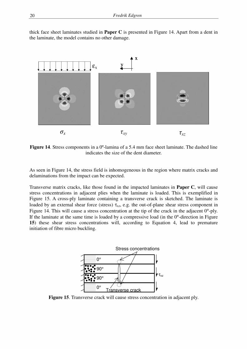
thick face sheet laminates studied in Paper C is presented in Figure 14. Apart from a dent in the laminate, the model contains no other damage.
x
y
x
y εx
�x �xy �xz
Figure 14. Stress components in a 0º-lamina of a 5.4 mm face sheet laminate. The dashed line indicates the size of the dent diameter.
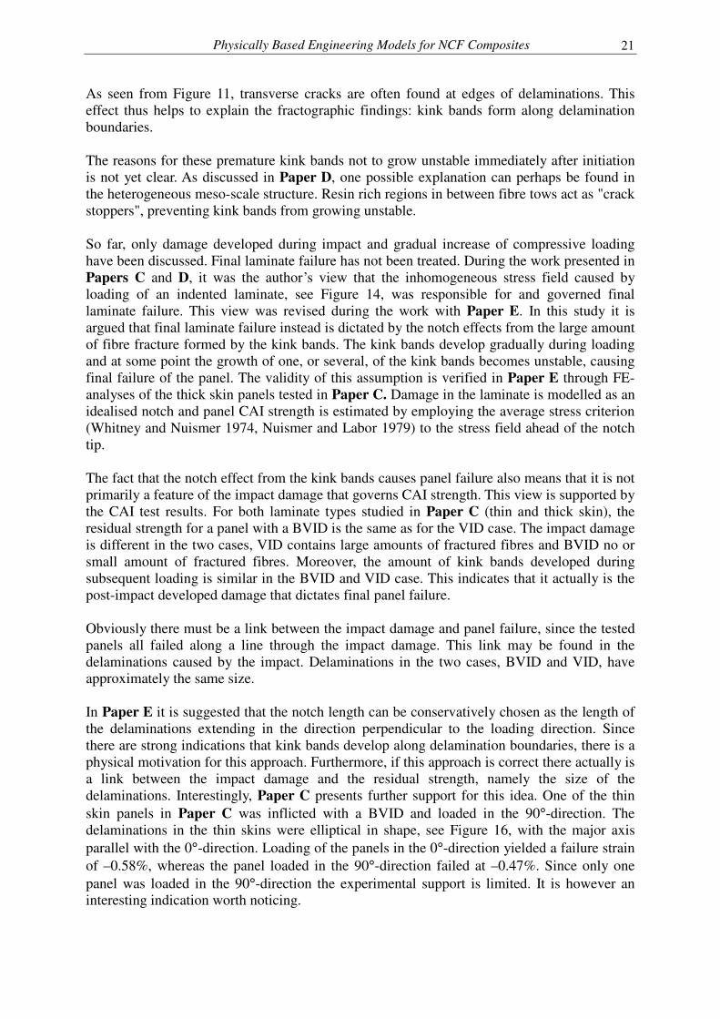
As seen in Figure 14, the stress field is inhomogeneous in the region where matrix cracks and delaminations from the impact can be expected. Transverse matrix cracks, like those found in the impacted laminates in Paper C, will cause stress concentrations in adjacent plies when the laminate is loaded. This is exemplified in Figure 15. A cross-ply laminate containing a transverse crack is sketched. The laminate is loaded by an external shear force (stress) τxz, e.g. the out-of-plane shear stress component in Figure 14. This will cause a stress concentration at the tip of the crack in the adjacent 0°-ply. If the laminate at the same time is loaded by a compressive load (in the 0°-direction in Figure 15) these shear stress concentrations will, according to Equation 4, lead to premature initiation of fibre micro buckling.
Transverse crack
0°
0°
90°
90° τxz
Stress concentrations
Figure 15. Transverse crack will cause stress concentration in adjacent ply.
Physically Based Engineering Models for NCF Composites
21
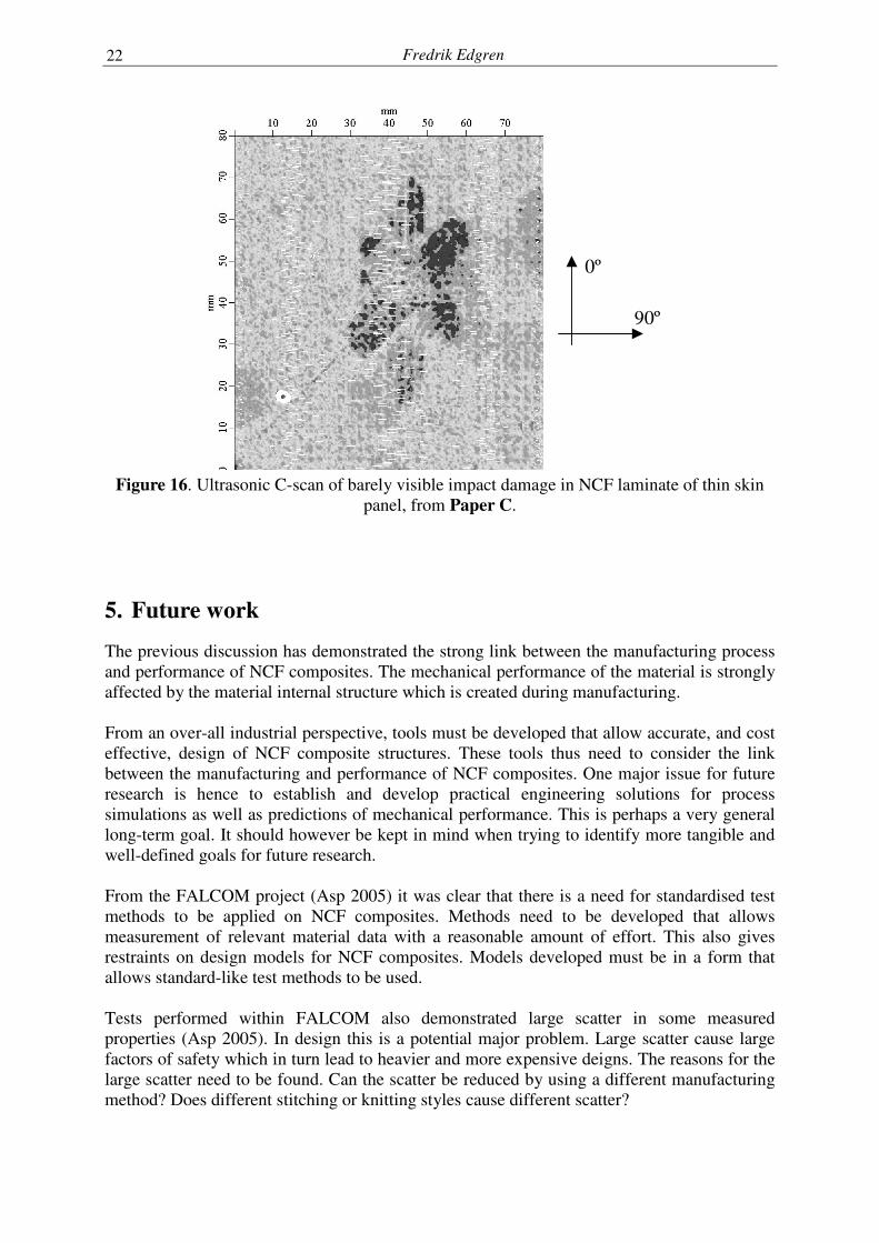
As seen from Figure 11, transverse cracks are often found at edges of delaminations. This effect thus helps to explain the fractographic findings: kink bands form along delamination boundaries. The reasons for these premature kink bands not to grow unstable immediately after initiation is not yet clear. As discussed in Paper D, one possible explanation can perhaps be found in the heterogeneous meso-scale structure. Resin rich regions in between fibre tows act as "crack stoppers", preventing kink bands from growing unstable. So far, only damage developed during impact and gradual increase of compressive loading have been discussed. Final laminate failure has not been treated. During the work presented in Papers C and D, it was the author’s view that the inhomogeneous stress field caused by loading of an indented laminate, see Figure 14, was responsible for and governed final laminate failure. This view was revised during the work with Paper E. In this study it is argued that final laminate failure instead is dictated by the notch effects from the large amount of fibre fracture formed by the kink bands. The kink bands develop gradually during loading and at some point the growth of one, or several, of the kink bands becomes unstable, causing final failure of the panel. The validity of this assumption is verified in Paper E through FE-analyses of the thick skin panels tested in Paper C. Damage in the laminate is modelled as an idealised notch and panel CAI strength is estimated by employing the average stress criterion (Whitney and Nuismer 1974, Nuismer and Labor 1979) to the stress field ahead of the notch tip. The fact that the notch effect from the kink bands causes panel failure also means that it is not primarily a feature of the impact damage that governs CAI strength. This view is supported by the CAI test results. For both laminate types studied in Paper C (thin and thick skin), the residual strength for a panel with a BVID is the same as for the VID case. The impact damage is different in the two cases, VID contains large amounts of fractured fibres and BVID no or small amount of fractured fibres. Moreover, the amount of kink bands developed during subsequent loading is similar in the BVID and VID case. This indicates that it actually is the post-impact developed damage that dictates final panel failure. Obviously there must be a link between the impact damage and panel failure, since the tested panels all failed along a line through the impact damage. This link may be found in the delaminations caused by the impact. Delaminations in the two cases, BVID and VID, have approximately the same size. In Paper E it is suggested that the notch length can be conservatively chosen as the length of the delaminations extending in the direction perpendicular to the loading direction. Since there are strong indications that kink bands develop along delamination boundaries, there is a physical motivation for this approach. Furthermore, if this approach is correct there actually is a link between the impact damage and the residual strength, namely the size of the delaminations. Interestingly, Paper C presents further support for this idea. One of the thin skin panels in Paper C was inflicted with a BVID and loaded in the 90°-direction. The delaminations in the thin skins were elliptical in shape, see Figure 16, with the major axis parallel with the 0°-direction. Loading of the panels in the 0°-direction yielded a failure strain of –0.58%, whereas the panel loaded in the 90°-direction failed at –0.47%. Since only one panel was loaded in the 90°-direction the experimental support is limited. It is however an interesting indication worth noticing.
Fredrik Edgren
22
0º
90º
Figure 16. Ultrasonic C-scan of barely visible impact damage in NCF laminate of thin skin
panel, from Paper C.
5. Future work
The previous discussion has demonstrated the strong link between the manufacturing process and performance of NCF composites. The mechanical performance of the material is strongly affected by the material internal structure which is created during manufacturing. From an over-all industrial perspective, tools must be developed that allow accurate, and cost effective, design of NCF composite structures. These tools thus need to consider the link between the manufacturing and performance of NCF composites. One major issue for future research is hence to establish and develop practical engineering solutions for process simulations as well as predictions of mechanical performance. This is perhaps a very general long-term goal. It should however be kept in mind when trying to identify more tangible and well-defined goals for future research. From the FALCOM project (Asp 2005) it was clear that there is a need for standardised test methods to be applied on NCF composites. Methods need to be developed that allows measurement of relevant material data with a reasonable amount of effort. This also gives restraints on design models for NCF composites. Models developed must be in a form that allows standard-like test methods to be used. Tests performed within FALCOM also demonstrated large scatter in some measured properties (Asp 2005). In design this is a potential major problem. Large scatter cause large factors of safety which in turn lead to heavier and more expensive deigns. The reasons for the large scatter need to be found. Can the scatter be reduced by using a different manufacturing method? Does different stitching or knitting styles cause different scatter?
Physically Based Engineering Models for NCF Composites
23
There is lack of general failure criteria for NCF composites. Several criteria are available for conventional composites. However, as demonstrated in this thesis, failure mechanisms in NCF composites can differ from those of prepregs. Attempts have been made to adjust general failure criteria to NCF composites (Asp 2005). Strength parameters needed to verify the applicability of the criteria were not possible to retrieve. Once again, this demonstrates the need for test methods, and design models, adapted to NCF composites. A more concrete research task concerns the indications on the link between the CAI strength and delamination size, as discussed in Paper E. A more thorough study should be performed investigating this issue. In Paper A the effects from out-of-plane tow waviness on reduction of laminate in-plane stiffness were investigated. Since in-plane tow waviness also is present in the laminate the knock-down effects from the combined waviness (in- and out-of-plane) should be investigated. Moreover, A very simple statistical tool was used in Paper A to quantify the amplitude of a sine wave with a certain (assumed) wavelength. Further work should be spent on finding statistical methods that better characterise the tow waviness.
6. References
Abrate S., 1991, Impact on laminated composite materials. Applied Mechanical Review. Vol. 44, No. 4, 155-190. Abrate S., 1994, Impact on laminated composite materials: Recent advances. Applied Mechanical Review. Vol. 47, No. 11, 517-544. Argon A.S., 1972, Fracture of composites. Vol. 1 of: Treatise of materials science and technology, 79-114, Academic Press, New York, USA. Asp L.E., Nilsson S., Singh S., 2001, An experimental investigation of the influence of delamination growth on the residual strength of impacted laminates. Composites Part A. Vol. 32, 1229-1235. Asp L.E., Edgren F., Sjögren A., 2004, Effects of stitch patternon the mechanical prperties of Non-crimp fabric composites. Proceedings of the 11th European Conference on Composite Materials (ECCM 11), Rhodes, Greece. Asp L.E., 2005. Competing factors in the selection and design of NCF architectures (processing/performance optimisation). Validation of local models by comparison with coupon data. Deliverable D4.5-01, Document No: FALCOM/WP4/SI/PM004. Report prepared under contract No: G4RD-CT-00694. May 2005. Avila-Dominguez, R., 2000, NCF processability and performance -A literature review-, DERA/MSS/MSMA2/WP003564, Farnborough, UK. Backer S., 1966, Fibrous materials, In: McClintock F.A. and Argon A.S. (eds.), Mechanical behaviour of materials, Addison-Wesley Publ., MA, USA.
Fredrik Edgren
24
Bishop S.M. 1989, Strength and Failure of woven carbon-fibre reinforced plastics for high performance applications. In: Chou T.W. and Ko F.K. (Eds.), Composite materials series Volume 3, Textile structural composites, Elsevier Science Publishers, Amsterdam. Bibo G.A., Hogg P.J., Kemp M., 1997, Mechanical characterisation of glass- and carbon fibre-reinforced composites made with non-crimp fabrics, Composites Science and Technology, Vol. 57, 1221-1241. Bibo G.A., Hogg P.J., 1998, Influence of reinforcement architecture on damage mechanisms and residual strength of glass-fibre/epoxy composite systems. Composites Science and Technology, Vol. 58, 803-813. Brandt, J., 2004, The Research Requirements of the Transport Sectors to Facilitate an Increased Usage of Composite Materials, Part I: The Composite Material Research Requirements of the Aerospace Industry, Report prepared under European Commission contract G4RT-CT-2001-05054, June 2004. Budiansky B.,1983, Micromechanics, Computers and Structures, Vol. 16, 3-12. Byun J.H., Chou T.W., 2000, Mechanics of textile composites. In: Chou T.W., Comprehensive composite materials, Volume 1 Fiber reinforcement and general theory of composites. Elsevier, UK. Chou T.W., 1992, Microstructural design of fiber composites. Cambridge University Press. Cox B.N., Dadkhah M.S., 1995, The macroscopic elasticity of 3D woven composites, Journal of Composite Materials, Vol. 29, 785-819. Cox, B.N., Flanagan, G., 1997, Handbook of analytical methods for textile composites, NASA contractor report 4750. Dartman, T., 2002, Flexible composites strength, deformation and fracture processes in woven and D.O.S. reinforcement materials. Doctoral thesis. Lund University, Lund, Sweden, ISBN: 91-628-5426-7. Dexter H.B., Hasko G.H., 1996, Mechanical properties and damage tolerance of multiaxial warp-knit composites, Composites Science and Technology, Vol. 56, 367-380. Dransfield K., Baillie C., Mai Y.W., 1994, Improving the delamination resistance of CFRP by stitching – a review. Composites Science and Technology, Vol. 50, 305-317. Dransfield K.A., Jain L.K., Mai Y.W., 1998, On the effects of stitching in CFRPs-I. Mode I delamination toughness, Composites Science and Technology, Vol. 58, 815-827. Drapier, S., Wisnom, M.R., 1999(a), Finite-element investigation of the compressive strength of non-crimp-fabric based composites. Composites Science and Technology, Vol. 59, 1287-1297.
Physically Based Engineering Models for NCF Composites
25
Drapier S., Wisnom M.R., 1999(b), A finite-element investigation of the interlaminar shear behaviour of non-crimp-fabric-based composites. Composites Science and Technology, Vol. 59, 2351-2362. Edgren F., Mattsson D., Asp L.E., Varna J., 2004, Formation of damage and its effects on non-crimp fabrics loaded in tension. Composites Science and Technology, Vol. 64, 675-692. EN6038, 1995, prEN 6038, Edition P1, Test method Determination of the compression strength after impact. AECMA, Brussels. EN 13473, 2001, EN 13473-1, Reinforcements - Specifications for multiaxial multi-ply stitched preforms – Part 1: Designation. European Committee for Standardization, Brussels. Filsinger J., Dittmann R.P, Bischoff T., 2004, Textile preforming technologies for fuselage applications, Proceedings of the 25th jubilee international SAMPE Europe Conference 2004 Paris E, 450-455. Fleck N.A., Budiansky B., 1990, Compressive failure of notched carbon fibre composites due to microbuckling, In: Dvorak G.J. (ed.), Inelastic deformation of composite materials, Springer, New York, 235-274. Fleck N.A., Compressive failure of composite materials. Advances in Applied Mechanics, Academic Press, New York, 1997: 43-117. Greenhalgh E., Hiley M., 2003, The assessment of novel materials and processes for the impact tolerant design of stiffened composite aerospace structures. Composites Part A. Vol. 34: 151-161. Hu J., Jiang Y., Ko F., 1998, Modeling uniaxial tensile properties of multiaxial warp knitted fabrics, Textile Research Journal, Vol. 68, No. 11, 828-834. Ilcewicz L.B., Hoffman D.J., Fawcett A.J., 2000, Composite Applications in Commercial Airframe Structures. In: Comprehensive Composite Materials, Volume 6: Design and Applications. Elsevier, UK. Jain L.K., Dransfield K.A., Mai Y.W., 1998, On the effects of stitching in CFRPs-II. Mode II delamination toughness, Composites Science and Technology, Vol. 58, 829-837. Joffe R., Krasnikovs A., Varna J., 2001, COD-based simulation of transverse cracking and stiffness reduction in [S/90n]s laminates. Composites Science and Technology, Vol. 61 637-656. Joffe R., Varna J., 2002, Effect of bundle waviness on compressive strength and notch sensitivity of non-crimp fabric composites Proceedings of IMECE'02, 2002 ASME International Mechanical Engineering Congress & Exposition, New Orleans, Louisiana, November 17-22, 2002. Joffe R., Mattsson D., Modniks J., Varna J., 2005, Compressive failure analysis of non-crimp fabric composites with large out-of-plane misalignment of fibre bundles. Composites A, Vol. 36 1030-1046.
Fredrik Edgren
26
Klopp K, Veihelmann B, Kolkmann A, Laourine E, Gries T, 2003, Use of reinforcement textiles in fiber reinforced plastics., Technical Textiles., Vol. 46, 59-63. Lee J.W., Harris C.H., 1990, A deformation-formulated micromechanics model of the effective Young’s modulus and strength of laminated composites containing local ply curvature. In: Garbo SP (ed.) Composite materials, testing and design, ASTM STP 1059, vol. 9. Philadelphia: American Society for Testing and Materials; 521-63. Lomov S.V., Verpoest I., Peeters T, Roose D., Zako M., 2003, Nesting in textile laminates: geometrical modelling of the laminate. Composites Science and Technology, Vol. 63, 993-1007. Lomov S.V., Belov E.B., Bischoff S.B., Ghosh S.B., Truong C.T., Verpoest I., 2002, Carbon composites based on multiaxial multiply stitched performs. Part 1. Geometry of the preform. Composites Part A. Vol. 33, 1171-1183. Mansfield, R.G., 2002, Textiles in stitches, Textile world, June 2002. Marsh G., 2004, Composite lift off in primary aerostructures. Reinforced Plastics, April, 2004. Nilsson K.-F., Asp L.E., Alpman J.E., Nystedt L., 2001, Delamination buckling and growth for delaminations at different depths in a slender composite panel. International Journal of Solids and Structures, Vol. 38, 3039-3071. Nuismer R.J., Labor J.D., 1979, Applications of the average stress failure criterion: Part II – Compression, Journal of Composite Materials. Vol. 13, 49-61. Olsson R., 1995, Prediction of impact damage in sandwich panels. Proc. Third international Conference on Sandwich Structures. EMAS, Solihull, UK, 659-668. Olsson R., 2000, Mass criterion for wave controlled impact response of composite plates. Composites Part A, Vol. 31, 879-887. Olsson R., Donadon M.V., Falzon B.G., 2006, Delamination threshold load for dynamic impact on plates. International Journal of Solids and Structures, In press. París F., González A., Graciani E., Flores M., del Castillo E., 2004, A 3D FEM study of compressive behaviour of non-crimp fabrics, (paper FM7), Proc. 11th European Conference on Composite Materials (ECCM11), Rhodes, Greece. Pavier M.J., Clarke M.P., 1996, Finite element prediction of the post-impact compressive strength of fibre composites. Composite Structures, Vol. 36, 141-153. Piggot M.R.,1995, The effect of fibre waviness on the mechanical properties of unidirectional fibre composites: a review. Composites Science and Technology, Vol. 53, 201-205. Purslow D., 1981, Some fundamental aspects of composites fractography. Technical Report 81127, Royal Aircraft Establishment, Farnborough, UK, October 1981.
Physically Based Engineering Models for NCF Composites
27
Scardino F., 1989, An introduction to textile structures and their behaviour. In: Chou T.W. and Ko F.K. (Eds.), Composite materials series Volume 3, Textile structural composites, Elsevier Science Publishers, Amsterdam. Steggal P., 1999, Developing multiaxial Non-crimp reinforcements for the cost effective solution. Proc. 31st international SAMPE Technical Conference, October, 1999. Soutis C., Curtis P.T., 1996, Prediction of the post-impact compressive strength of CFRP laminated composites. Composites Science and Technology, Vol. 56, 677-684. Truong C.T., Vettori M., Lomov S., Verpoest I., 2005, Carbon composites based on mult-iaxial multi-ply stitched performs. Part 4. Mechanical properties of composites and damage observation, Composites Part A. Vol. 36, 1207-1221. Varna J., 2001, Mechanics of damaged fibre reinforced composite laminates. Proc. Of the 2nd International Conference on Fracture and Damage, FDM 2001, Milan, Italy, 359-364. Whitcomb J.D., 1981, Finite element analysis of instability related delamination growth. Journal of Composite Materials. Vol. 15, 403-426. Whitney J.M., Nuismer R.J., 1974, Stress fracture criteria for laminated composites containing stress concentrations, Journal of Composite Materials. Vol. 8, 253-265. Åström B.T., 1997, Manufacturing of polymer composites. Chapman & Hall, London, UK.