Physical Layer Security Performance Study for Two-Hop ...
116
Physical Layer Security Performance Study for Two-Hop Wireless Networks with Buffer-Aided Relay Selection by Xuening Liao A dissertation submitted in partial fulfillment of the requirements for the degree of Doctor of Philosophy (The School of Systems Information Science) in Future University Hakodate September, 2018
Transcript of Physical Layer Security Performance Study for Two-Hop ...
Physical Layer Security Performance Study forTwo-Hop Wireless Networks with Buffer-Aided
Relay Selection
by
Xuening Liao
A dissertation submitted in partial fulfillmentof the requirements for the degree of
Doctor of Philosophy(The School of Systems Information Science)
in Future University HakodateSeptember, 2018

To my family
ii
ABSTRACT
Physical Layer Security Performance Study for Two-Hop Wireless Networks withBuffer-Aided Relay Selection
by
Xuening Liao
As wireless communication technologies continue to evolve rapidly, an unprecedented
amount of sensitive information, such as financial data, physical health details and
personal profile data, are transmitted through various wireless networks. Howev-
er, the broadcast nature of wireless medium makes it difficult to shield these sensi-
tive information from unauthorized users (eavesdroppers), and thus securing wireless
communication is becoming an increasingly urgent demand. Physical layer (PHY)
security has been proposed as one promising technology to provide security guar-
antee for wireless communications, owing to its unique advantages over traditional
cryptography-based mechanisms, like an everlasting security guarantee and no need
for costly secret key distribution/management and complex encryption algorithm-
s. This thesis therefore focuses on the PHY security performance study for two-hop
wireless networks with buffer-aided relay selection (a typical PHY security technique),
where relay buffers will be adopted to help the transmission of the message.
We first investigate the security-delay trade-off of the buffer-aided relay selection
scheme in a two-hop wireless network with multiple randomize-and-forward (RF) re-
iii
lays where different codebooks are used at the source and the relays respectively.
To evaluate the security and delay performances of the system, we derive analytical
expressions for the end-to-end (E2E) secure transmission probability (STP) and the
expected E2E delay under both perfect and partial eavesdropper channel state in-
formation (CSI) cases. These analytical expressions help us to explore the inherent
trade-off between the security and delay performances of the concerned system. In
particular, the results in this thesis indicate that: 1) the maximum E2E STP increas-
es as the constraint on the expected E2E delay becomes less strict, and such trend is
more sensitive to the variation of the number of relays than that of the relay buffer
size; 2) on the other hand, the minimum expected E2E delay tends to decrease when
a less strict constraint on E2E STP is imposed, and this trend is more sensitive to
the variation of the relay buffer size than that of the number of relays. This work is
very important and can really reflect the interplay between the overall security and
delay performances of two-hop wireless networks with RF relays.
We then investigate the PHY security performances of two-hop wireless networks
with multiple decode-and-forward (DF) relays where the same codebook is adopted
at the source and the relays, for which we extend the buffer-aided relay selection
with RF relays and propose a new buffer-aided relay selection scheme to resist the
combining decoding of the signals by the eavesdropper in two-hop wireless networks
with DF relays. To validate the efficiency of the new scheme, a theoretical framework
is developed to analyze the E2E delivery process of a packet. Based the theoretical
framework, we derive the closed form of the security and delay performances in terms
of the E2E STP and the expected E2E delay. Then, extensive numerical results are
conducted to validate the efficiency of the new buffer-aided relay selection scheme,
and to explore the security-delay trade-off issue of the achievable E2E STP (expected
E2E delay) region under a given expected E2E delay (E2E STP) constraint. Finally,
comparisons are made between the new buffer-aided relay selection scheme and the
iv
conventional Max-Ratio scheme, and results show that our new scheme outperforms
the Max-Ratio buffer-aided relay selection scheme in terms of the E2E STP. This
work can provide theoretical models for the E2E security and delay performances of
two-hop wireless networks with DF relays, and can be employed as guidelines for the
design of future networks.
v

ACKNOWLEDGEMENTS
During my three-year doctoral career in Future University Hakodate, I would like
to express my sincere thanks to all who provided me love and encouragement. The
thesis would not have been possible without all their help. The experience here is
certainly one of the most important and wonderful one which I will never forget in
the rest of my life.
First and foremost, I would like to thank my advisor Professor Xiaohong Jiang,
not only for his the financial support for me, but also for his encouragement and
guidance on my research. It is honorable for me to be one of his students and I
learned a lot from him which is very helpful for me to deal with difficulties in my life.
During my studying here, he and his wife, Mrs Li, gave a lot of care for me, which
made me very worm. The life in Hakodate would be very hard without the help of
them.
Besides, I would like to thank Yuanyu Zhang for his help with my research. He
gave me many good advices during the research to make the quality of my papers
better. I also thank other members in our laboratory Xiaolan Liu, Lisheng Ma, Bo
Liu, Wu Wang, Jia Liu, Ji He, Yongchao Dang, Huihui Wu and Xiaochen Li for their
help with this thesis.
I would also like to acknowledge my thesis committee members, Professor Yuichi
Fujino, Professor Hiroshi Inamura and Professor Masaaki Wada, for their constructive
comments that help to improve the quality of my thesis.
I would also like to give my sincere thanks to Professor Zhenqiang Wu of Shaanxi
vi

Normal University, China, who gave me the chance to do research in Hakodate with
Professor Jiang and other members in Professor Zhenqiang Wu’s laboratory. He is the
person who encouraged me to see a different world and try new things, and showed
me the way to be a better researcher.
Last but the least. I would like to thank my family. I would like to thank my
parents, whose love and guidance are with me in whatever I peruse and also my
brothers for their love for me. Specially, I would like to thank for my boyfriend Lu
He who gave me unconditional support such that I have the courage to face any
difficulties.
vii

TABLE OF CONTENTS
DEDICATION . . . . . . . . . . . . . . . . . . . . . . . . . . . . . . . . . . ii
ABSTRACT . . . . . . . . . . . . . . . . . . . . . . . . . . . . . . . . . . . iii
ACKNOWLEDGEMENTS . . . . . . . . . . . . . . . . . . . . . . . . . . vi
LIST OF FIGURES . . . . . . . . . . . . . . . . . . . . . . . . . . . . . . . xi
LIST OF APPENDICES . . . . . . . . . . . . . . . . . . . . . . . . . . . . xii
CHAPTER
I. Introduction . . . . . . . . . . . . . . . . . . . . . . . . . . . . . . 1
1.1 Physical Layer Security . . . . . . . . . . . . . . . . . . . . . 1
1.2 Objective and Main Works . . . . . . . . . . . . . . . . . . . 5
1.2.1 PHY Security Performance Study of Buffer-AidedRelay Selection Scheme for Two-Hop Wireless Net-works with RF Relays . . . . . . . . . . . . . . . . . 6
1.2.2 PHY Security Performance Study of Buffer-AidedRelay Selection Scheme for Two-Hop Wireless Net-works with DF Relays . . . . . . . . . . . . . . . . . 8
1.3 Thesis Outline . . . . . . . . . . . . . . . . . . . . . . . . . . 9
1.4 Notations . . . . . . . . . . . . . . . . . . . . . . . . . . . . . 10
II. Related Works . . . . . . . . . . . . . . . . . . . . . . . . . . . . . 13
2.1 PHY Security Performance Study of Buffer-Aided Relay Selec-tion Scheme for Two-Hop Wireless Networks with RF Relays 13
2.2 PHY Security Performance Study of Buffer-Aided Relay Selec-tion Scheme for Two-Hop Wireless Networks with DF Relays 15
viii
III. Physical Layer Security Performance Study of Buffer-AidedRelay Selection Scheme for Two-Hop Wireless Networks withRF Relays . . . . . . . . . . . . . . . . . . . . . . . . . . . . . . . . 19
3.1 Outline . . . . . . . . . . . . . . . . . . . . . . . . . . . . . . 203.2 System Model and Definitions . . . . . . . . . . . . . . . . . . 20
3.2.1 System Model . . . . . . . . . . . . . . . . . . . . . 203.2.2 Transmission and Buffer-Aided Relay Selection Schemes 223.2.3 Performance Metrics . . . . . . . . . . . . . . . . . 25
3.3 General Framework for E2E Packet Delivery Process Modeling 273.3.1 Source-Relay Delivery Process Modeling . . . . . . . 283.3.2 Relay-Destination Delivery Process Modeling . . . . 30
3.4 E2E STP and Delay Analysis . . . . . . . . . . . . . . . . . . 323.4.1 E2E STP Analysis . . . . . . . . . . . . . . . . . . . 333.4.2 E2E Delay Analysis . . . . . . . . . . . . . . . . . . 36
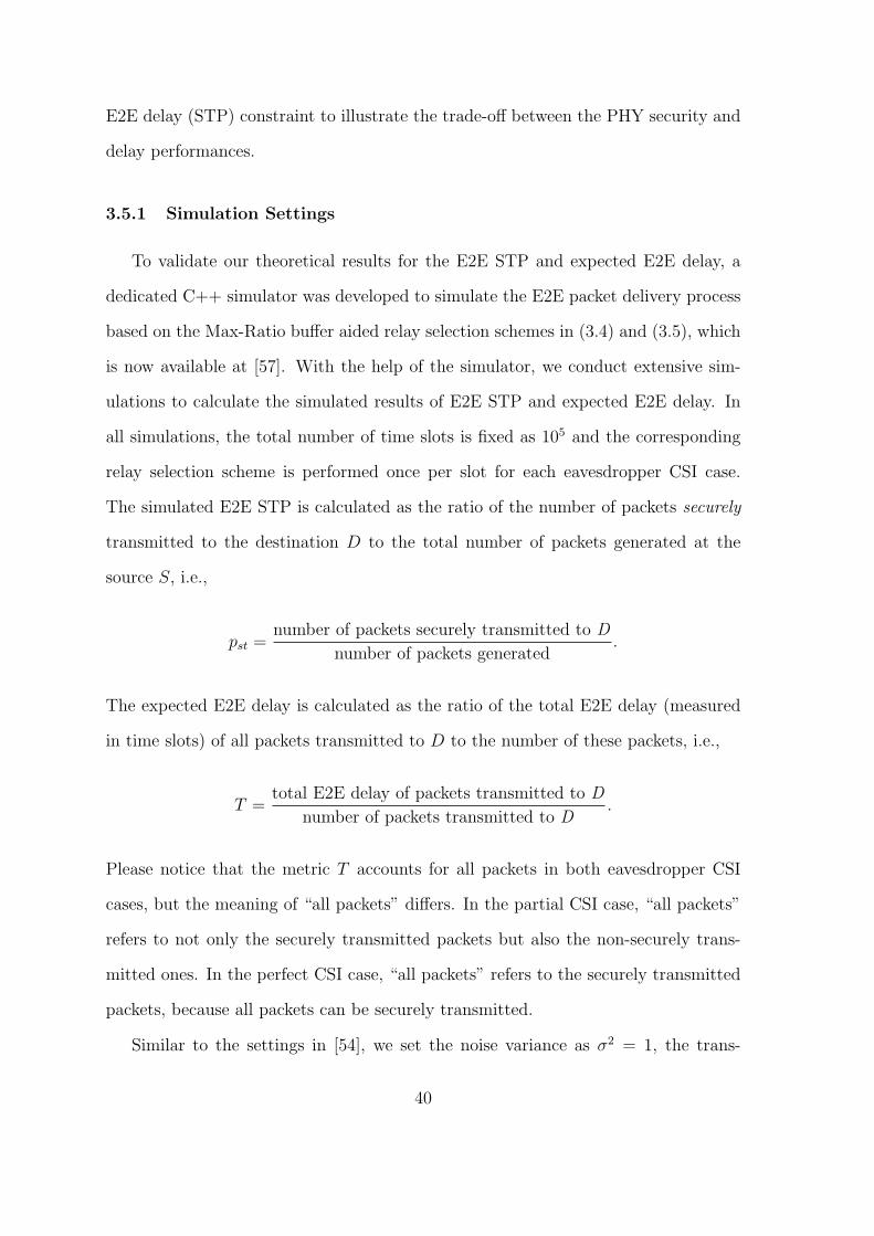
3.5 Simulation results . . . . . . . . . . . . . . . . . . . . . . . . 393.5.1 Simulation Settings . . . . . . . . . . . . . . . . . . 403.5.2 Model Validation . . . . . . . . . . . . . . . . . . . 413.5.3 Performance Discussion . . . . . . . . . . . . . . . . 423.5.4 Security-Delay Trade-Off Analysis . . . . . . . . . . 45
3.6 Summary . . . . . . . . . . . . . . . . . . . . . . . . . . . . . 49
IV. Physical Layer Security Performance Study of Buffer-AidedRelay Selection Scheme for Two-Hop Wireless Networks withDF Relays . . . . . . . . . . . . . . . . . . . . . . . . . . . . . . . . 51
4.1 System Model and Assumptions . . . . . . . . . . . . . . . . 524.2 New Buffer-Aided Relay Selection Scheme . . . . . . . . . . . 54
4.2.1 New Buffer-Aided Relay Selection Scheme . . . . . . 554.2.2 Performance Metrics . . . . . . . . . . . . . . . . . 56
4.3 E2E STP and Delay Analysis . . . . . . . . . . . . . . . . . . 574.4 Numerical Results and Discussions . . . . . . . . . . . . . . . 62
4.4.1 Simulation Settings . . . . . . . . . . . . . . . . . . 624.4.2 Model Validation . . . . . . . . . . . . . . . . . . . 634.4.3 Performance Discussion . . . . . . . . . . . . . . . . 654.4.4 Security-Delay Trade-Off Analysis . . . . . . . . . . 674.4.5 Effects of Eavesdropper’s Decoding Strategy on E2E
STP and E2E Delay . . . . . . . . . . . . . . . . . . 704.5 Summary . . . . . . . . . . . . . . . . . . . . . . . . . . . . . 72
V. Conclusions . . . . . . . . . . . . . . . . . . . . . . . . . . . . . . . 75
5.0.1 Summary of the Thesis . . . . . . . . . . . . . . . . 755.0.2 Future Works . . . . . . . . . . . . . . . . . . . . . 77
ix

APPENDICES . . . . . . . . . . . . . . . . . . . . . . . . . . . . . . . . . . 81A.1 Proof of Lemma 1 . . . . . . . . . . . . . . . . . . . . . . . . 83B.1 Proof of Lemma 5 . . . . . . . . . . . . . . . . . . . . . . . . 87
BIBLIOGRAPHY . . . . . . . . . . . . . . . . . . . . . . . . . . . . . . . . 91
Pulications . . . . . . . . . . . . . . . . . . . . . . . . . . . . . . . . . . . . 103
x
LIST OF FIGURES
Figure
3.1 Illustration of the system model. . . . . . . . . . . . . . . . . . . . . 213.2 End-to-end delivery process of a packet. . . . . . . . . . . . . . . . . 273.3 E2E STP and expected E2E delay vs. target secrecy rate ε. . . . . . 423.4 E2E STP and expected E2E delay vs. number of relays N . . . . . . 443.5 E2E STP and expected E2E delay vs. buffer size L. . . . . . . . . . 453.6 Maximum achievable E2E STP vs. E2E delay constraint τ . . . . . . 463.7 Minimum achievable expected E2E delay vs. E2E STP constraint ρ. 484.1 Network model. . . . . . . . . . . . . . . . . . . . . . . . . . . . . . 544.2 Simulation results vs. theoretical results for E2E STP and expected
E2E delay with different target secrecy rate ε. . . . . . . . . . . . . 644.3 Simulation results vs. theoretical results for E2E STP and expected
E2E delay with different number of relays N . . . . . . . . . . . . . . 654.4 Simulation results vs. theoretical results for E2E STP and expected
E2E delay with different buffer size L. . . . . . . . . . . . . . . . . . 664.5 Maximum achievable E2E STP vs. expected E2E delay constraint τ . 684.6 Minimum achievable expected E2E delay vs. E2E STP constraint ρ. 694.7 E2E STP vs. target secrecy rate ε with different relay selection schemes. 714.8 Expected E2E delay vs. target secrecy rate ε with different relay
selection schemes. . . . . . . . . . . . . . . . . . . . . . . . . . . . . 72
xi

LIST OF APPENDICES
Appendix
A. Proofs in Chapter III . . . . . . . . . . . . . . . . . . . . . . . . . . . 83
B. Proofs in Chapter IV . . . . . . . . . . . . . . . . . . . . . . . . . . . 87
xii
CHAPTER I
Introduction
In this chapter, we first introduce the background of physical layer security and
then present the objective and main works of this thesis. Finally, we give the outline
and main notations of this thesis.
1.1 Physical Layer Security
As wireless communication technologies continue to evolve rapidly, an unprece-
dented amount of sensitive information, such as financial data, physical health details
and personal profile, will be transmitted through various wireless networks in the near
future [1]. However, the broadcast nature of wireless medium makes it difficult to
shield these sensitive information from unauthorized users (eavesdroppers), and thus
security of wireless communication is becoming an increasingly urgent demand [2].
Traditionally, security issue is addressed by cryptographic methods which utilize
secret keys and encryption/decryption algorithms to ensure the security of the trans-
mitted information above the physical layer [3], [4]. A key premise of these methods
is that eavesdroppers have limited computational capability such that the encryption
algorithms are computationally infeasible for them to decrypt without the secret keys
[4]. Unfortunately, this premise has been challenged as eavesdroppers are becoming
increasingly computationally powerful [5]. Recently, the technology of physical layer
1
(PHY) security, which secures information at the physical layer by exploiting the
inherent randomness of wireless channels and noise, has attracted considerable atten-
tions [6]. Compared to cryptographic methods, PHY security technology can enjoy
the following major advantages. First, PHY security technology eliminates the costly
secret key distribution/management and encryption/decryption algorithms in cryp-
tographic methods, making it more suitable for resource-limited wireless networks
[7]. Second, different from cryptographic methods, PHY security technology assumes
no limitations for eavesdroppers in terms of the computational capability, making
it completely immune to the rapid advances in computing power of eavesdroppers
[7]. Third, unlike the computational security achieved by cryptographic methods,
PHY security approaches can achieve the information-theoretic security [8], which
is regarded as an everlasting security guarantee and can be quantified precisely by
multiple criteria like secrecy rate [9], [10], secrecy throughput [11], [12], and secrecy
outage probability [13], [14]. Therefore, PHY security technology has been recognized
as a highly promising approach to provide a strong form of security guarantee for the
next-generation wireless communication networks [15].
The first work regarding the PHY security is conducted by Wyner [16], who
introduced the wiretap channel in his paper. In the wiretap model, three nodes
are included: a transmitter, a receiver and an eavesdropper. The transmitter wishes
to transmit secure information to the legitimate receiver over a noisy main channel,
and the eavesdropper attempts to intercept the information transmitted over the
main channel though another noisy channel, which is called the wiretap channel or
eavesdropper channel. It has been revealed by Wyner in his paper that, when the
main channel is better than the eavesdropper channel, a non-zero secrecy rate can
be achieved. This result is of great importance as it proves that information can be
secured without a secret key, which will greatly save the cost of key distribution and
management in secure communications. Wyner’s work was then generalized by Csizar
2

and Korner in [17], their results showed that a non-zero secrecy rate is also achievable
even when the main channel is not better than the eavesdropper channel, and they
proved that this can be achieved by exploiting the technique of channel prefix to inject
additional randomness into both the main and the eavesdropper channels to create
a better main channel over the eavesdropper channel. Following these two works,
extensive research efforts have been devoted to studies on the PHY security techniques
by exploiting the randomness of wireless channels and noise. These techniques mainly
includes artificial noise injection/cooperative jamming [18–20], beam-forming [21–23],
coding [24–26] and relay selection with or without the consideration of relay buffers
[27–40], etc.
Artificial noise injection/cooperative jamming ensures the security of wireless net-
works by adopting the non-transmitting nodes to act as jammers to transmit jamming
signals to the eavesdropper, such that the signals received at the eavesdropper can
be degraded. According to the types of jamming signals, cooperative jamming can
be classified into two categories. One is cooperative jamming with Gaussian noise
jamming signal which will cause interference to both the legitimate receivers and
the eavesdropper [18]. Another is cooperative jamming with jamming signal of the
same codebook and the jamming signal is predefined with a certain structure and
thus can be eliminated at the intended receiver [20]. For the first category of co-
operative jamming, the jamming process can be conducted without the requirement
of the eavesdropper’s channel state information (CSI), while the legitimate channel-
s may be affected by the jamming signals. For the second category of cooperative
jamming, a better security performance can be obviously achieved. However, due to
the requirement of a certain structure of the jamming signals, the construction of
the codebook is very complex and it usually requires the jammer to be located closer
to the eavesdropper than to the intended receiver, which is not always possible in
practice, especially for eavesdroppers who only wiretap the legitimate channel and
3
transmit no information all over the time.
Beam-forming is usually exploited in the multiple-in-multiple-out (MIMO) net-
work, where all nodes are equipped with antennas and one data stream can be trans-
mitted to the intended receiver over multiple antennas. It enhances the security of
information transmitted in the network by controlling the direction and strength of
signal such that the signal is radiated towards the direction of the intended receiv-
er, while receivers in other directions can hardly receive the signal [22]. It has been
proved in [21] that beam-forming can maximize the secrecy capacity of wireless net-
works by optimizing the beam-forming weights at the source and relay nodes. How-
ever, this technique requires high coordinations (such as synchronization and central
optimization) among the source and relay nodes, which usually needs high overhead
in implementation, as a large amount of information will be exchanged between the
nodes. Moreover, to obtain better efficiency, the design of cooperative jamming also
requires the CSI of the eavesdropper channels.
Coding aims to improve the security of wireless networks based on the idea of
stochastic encoding [24]. For each legitimate information, the coding technique en-
codes the legitimate message together with multiple protection messages which carry
no information. First, it will randomly choose a protection message and then asso-
ciates the legitimate information and the protection message together into a single
codeword. If the legitimate channel is better than the eavesdropper channel, the pro-
tection message is designed detrimental enough to interfere with the eavesdropper,
but can remains ensure the resolvability of the confidential message at the intended
receiver. This technique can notably achieve high security performance of the net-
work, but the constructing of the codebook is hard and even challenging. Similar to
the majority of the above two PHY secuirty techniques, coding also requires the CSI
knowledge of the eavesdropper channel.
The relay selection technique aims to improve the security of wireless networks
4

by choosing a relay (called message relay) with a strong legitimate link but a weak
eavesdropper link. According to whether the relay buffers are introduced or not,
relay selection can be divided into two categories, i.e., relay selection without buffer-
s (traditional relay selection) [27–29] and relay selection with buffers (buffer-aided
relay selection) [30–40]. For traditional relay selection, its transmission manner is
prefixed, i.e., the source-relay-destination transmission manner. If a relay is selected,
the transmission of the information can be finished in two consecutive time slots. In
the first time slot, the source transmits the information to the message relay and the
message relay will directly transmit the information to the destination in the next
time slot even if the current transmission link is not secure enough for transmission.
However, for the buffer-aided relay selection, if a relay is selected for transmission, it
can store the information in its buffer to wait for a better transmission link. Thus,
each information now may go through three processes, i.e., the source-relay trans-
mission process, queuing process in a relay buffer and the relay-destination transmis-
sion process, and in each time slot, there are three possible transmission states, i.e.,
source-relay transmission, relay-destination transmission and no transmission. Com-
pared with the traditional relay selection, authors in [33] showed that buffer-aided
relay can achieve a full diversity gain which is two times the number of relays in
the network. Different from other PHY security techniques above, the relay selection
technique is easy to be accomplished and it has no extra bad effect on the signals at
the legitimate nodes, while the design of relay selection may also requires the CSI of
the eavesdropper channel.
1.2 Objective and Main Works
This thesis adopts the buffer-aided relay selection with Gaussian noise to ensure
the security of wireless communications, considering its possibility of being imple-
mented in practice with different network scenarios. Our objective is to fully explore
5

the PHY security performances of buffer-aided relay selection for two-hop wireless net-
works. Towards this end, we first study the PHY security performances of buffer-aided
relay selection scheme for two-hop wireless networks with randomize-and-forward (R-
F) relays where eavesdropper can only decode the packet in two hops independently.
We then investigate the PHY security performances of buffer-aided relay selection
scheme for two-hop wireless networks with decode-and-forward (DF) relays where
the same codebook is adopted at the source and the relay nodes, and the eavesdrop-
per can thus decode the packet by combing the signals received in two hops. Two
commonly-used PHY security performance metrics are of particular interest, which
are the end-to-end (E2E) secure transmission probability (STP) and E2E delay [39].
E2E STP characterizes the probability of successfully transmitting a packet from the
source to the destination and E2E delay defines the time slots it takes a packet to
reach its destination after it is generated at the source node. The main works and
contributions of this thesis are summarized in the following subsections.
1.2.1 PHY Security Performance Study of Buffer-Aided Relay Selection
Scheme for Two-Hop Wireless Networks with RF Relays
This work focuses on the security-delay trade-off study of the buffer-aided re-
lay selection scheme for two-hop wireless networks with RF relays. While existing
works [30–37] regarding the security performance study of two-hop wireless network-
s with buffer-aided relay selection mainly derived security performance of a single
link (Please refer to Section 2.1 for related works), the E2E security performance
of such networks remains largely unexplored. Moreover, the delay issue has not
been addressed yet. In this work, as a first step towards the study of E2E security
and delay performances for two-hop wireless networks with buffer-aided relay selec-
tion, we study the E2E STP and E2E delay of a two-hop wireless network with one
source-destination pair, multiple RF relays and an eavesdropper intercepting both
6

the source-relay and relay-destination links. We consider the Max-Ratio buffer-aided
relay selection scheme to select the message relay for receiving packets from the source
or forwarding packets to the destination node. The main contributions of this work
can be summarized as follows:
• Analytical expressions for E2E secure transmission probability (STP) and ex-
pected E2E delay: we consider a two-hop relay system, which consists of a
source-destination pair, one eavesdropper and multiple relays each having a fi-
nite buffer, and study the E2E security and delay performances of the system
under both perfect and partial eavesdropper CSI cases. To derive the E2E per-
formances, we develop a theoretical framework consisting of two Markov chains,
here the first one characterizes the buffer states for a packet in its source-relay
delivery process while the second one characterizes the buffer states for the
packet in its relay-destination delivery process. With the help of the frame-
work, the analytical expressions for the E2E STP and the expected E2E delay
are derived to evaluate the security and delay performances of the system.
• Study on the security-delay trade-off: based on the analytical expressions on
the E2E STP and expected E2E delay, we provide extensive numerical results
to illustrate our theoretical findings. These results indicate that there is a clear
trade-off between the E2E security performance and delay performance in the
concerned system. For example, if we impose a larger upper bound (i.e., a less
strict constraint) on the expected E2E delay, the maximum E2E STP (in terms
of either relay buffer size or number of relays) tends to increase, and such trend
is more sensitive to the variation of the number of relays than that of the relay
buffer size. On the other hand, if we impose a smaller lower bound (i.e., a more
strict constraint) on the E2E STP, the minimum expected E2E delay (in terms
of either relay buffer size or number of relays) tends to decrease, and this trend
7
is more sensitive to the variation of the relay buffer size than that of the number
of relays.
With this work, we can further explore the overall interplay between the PHY se-
curity security and the delay performances for two-hop wireless networks with buffer-
aided relay selection, which is of great importance for the design of future networks.
1.2.2 PHY Security Performance Study of Buffer-Aided Relay Selection
Scheme for Two-Hop Wireless Networks with DF Relays
The available buffer-aided relay selection schemes consider mainly the networks
with RF relays (Please refer to Section 2.1 for related works), which may significantly
limit their applications to wireless networks with DF relays where the eavesdropper
can decode the information by combining the signals received in two hops. This work
considers a new two-hop wireless network with a source-destination pair, multiple DF
relays each having a finite buffer and an eavesdropper who can combine the signals
in two hops to conduct its decoding. A new buffer-aided relay selection scheme is
proposed to resist the eavesdropper and we attempt to explore the effects of such
eavesdropper’s decoding strategy on the concerned network in terms of the E2E STP
and expected E2E delay. The contributions of this work are summarized as follows.
• Propose new buffer-aided relay selection scheme to resist the eavesdropper’s
combining decoding. This is achieved to select the message relay by considering
not only the link quality of the main and the eavesdropper channels and the
relay buffer states, but also the eavesdropper’s decoding strategy.
• Derive analytical expressions for E2E STP and expected E2E delay for both cas-
es when either the instantaneous CSI, or only the distribution of eavesdropping
channels are available: A theoretical framework which consists of two Markov
chains are developed to derive the E2E performances. The first Markov chain
8

characterizes the buffer states for a packet in its source-relay delivery process,
and the second Markov chain characterizes the buffer states for the packet in
its relay-destination delivery process. With the help of the framework, the E2E
STP and the expected E2E delay are derived to evaluate the security and delay
performance of the proposed buffer-aided relay selection scheme.
• Conduct extensive numerical results to validate the efficiency of the proposed
buffer-aided relay selection schemes in terms of the E2E STP and the expected
E2E delay. Based on the theoretical results, the security-delay trade-off issue is
then studied to explore the achievable E2E STP (expected E2E delay) region
under a given expected E2E delay (E2E STP) constraint. Finally, comparisons
are made between the new buffer-aided relay selection scheme and the con-
ventional Max-Ratio scheme in terms of the E2E STP and expected E2E delay,
results show that our new scheme outperforms the Max-Ratio buffer-aided relay
selection scheme in terms of the E2E STP.
By conducting this work, we can provide theoretical models for the E2E security
and delay performances of two-hop wireless networks with DF relays, which can be
employed as guidelines for network designers.
1.3 Thesis Outline
The remainder of this thesis is outlined as follows. Chapter II introduces the
related works of this thesis. In Chapter III, we introduce our work regarding PHY
security performance study of buffer-aided relay selection scheme for two-hop wireless
networks with RF relays, and Chapter IV presents the work on PHY security per-
formance study of buffer-aided relay selection scheme for two-hop wireless networks
with DF relays. Finally, we conclude this thesis in Chapter V.
9

1.4 Notations
The main notations of this thesis are summarized in Table 1.1.
Table 1.1: Main notations
Symbol Definition
S source node
D destination node
E eavesdropper
N number of relays
Rn the n-th relay
R∗ selected message relay
Qn queue of relay Rn
Ψ(Qn) number of packets in the relay Rn’s queue
|hi,j|2 channel gain of link from node i to j
C i,js instantaneous secrecy of link i to j
ε target secrecy rate
E[·] expectation operator
f(·) probability-density-function (PDF)
F (·) cumulative-density-function (CDF)
P[·] probability operator
P common transmit power of source and relay nodes
σ noise variance
Rt transmission rate of the main channel
Rs secrecy rate
γse average channel gains of the source-eavesdropper link
γre average channel gains of the relay-eavesdropper link
α average channel gain ratio of the first hop
10

β average channel gain ratio of the second hop
pst end-to-end (E2E) secure transmission probability (STP)
T E2E delay
Ts service time at the source node
Tr service time at the relay node
Tq queuing delay at the relay node
τ E2E delay delay constraint
ρ E2E STP constraint
S+i sets of states si can move to for a successful source-relay trans-
mission
S−i sets of states si can move to for a successful relay-destination
transmission
N1 number of available relays for the source-relay transmission
N2 number of available relays for the relay-destination transmission
si relay buffer state
Θsi the set of states that have the same stationary probability as si
Ξ(si,Θsj) the set of states that state si has to pass through to reach a
state in Θsj
A Markov chain for the source-relay delivery process
A Markov chain for the relay-destination delivery process
ai,j entry of the Markov chain for source-relay delivery process
ai,j entry of the Markov chain for relay-destination delivery process
πsi stationary probability of state si in the source-relay delivery
process
πsi stationary probability of state si in the relay-destination delivery
process
11


CHAPTER II
Related Works
This section introduces the existing works related to our study in this thesis,
including the works on the E2E performance study of buffer-aided relay selection
for two-hop wireless networks with RF relays and the works on the PHY security
performance study of buffer-aided relay selection for two-hop wireless networks with
DF relays.
2.1 PHY Security Performance Study of Buffer-Aided Relay
Selection Scheme for Two-Hop Wireless Networks with
RF Relays
By now, many works have been devoted to the study on the PHY security per-
formances of wireless networks with buffer-aided relay selection [30–37]. These works
mainly focused on two-hop relay systems with one source-destination pair and sin-
gle/multiple relays. For the scenario with single relay, the buffer-aided relay selection
problem reduces to the selection of a link among the links of source-relay, relay-
destination and source-destination to meet a given security criteria [30–32]. For the
relay system with a half-duplex (HD) relay where no direct source-destination link is
available, the authors in [30] proposed two link selection policies with the considera-
13
tions of both transmission efficiency and secrecy constraints. They also considered the
secrecy throughput maximization problem under secrecy outage probability (SOP)
constraint and the SOP minimization problem under secrecy throughput constraint.
This work was then extended to the scenario with a full-duplex (FD) relay in [31],
where the authors proposed a hybrid HD/FD relaying scheme that allows the relay
to switch between the FD mode and HD mode. The optimal setting of mode switch-
ing probability was also examined in [31] for the maximization of secrecy network
throughput. For the relay system with direct source-destination link, the authors in
[32] proposed a link selection scheme based on artificial noise injection, where the
node not involved in the transmission serves as a jammer for noise injection. The
secrecy throughput maximization issue was also explored in [32] under certain SOP
constraint.
Regarding the two-hop relay systems with multiple relays, the authors in [33] con-
sidered the case when there is only one eavesdropper and proposed relay selection
schemes under both the perfect and partial eavesdropper CSI assumptions, where
a link is selected based on the channel gain ratio between the main channel and
the eavesdropping channel. The SOP of the selected link was derived to evaluate
the security performance of the proposed schemes. This work was then extended
in [34], where the relay selection is based on the instantaneous secrecy capacity of
the individual links. For a MIMO relay system with one eavesdropper and unknown
eavesdroppers CSI, the authors in [35] and [36] proposed a link selection scheme based
on the maximum legitimate channel gain and derived the corresponding SOP perfor-
mance of the selected link. The authors in [37] also considered a MIMO system in the
presence of multiple eavesdroppers. Under the assumption of perfect eavesdroppers’
CSI, they combined the relay selection scheme in [33] with the cooperative jamming
technique and proposed a greedy algorithm to identify the best link and jammer to
maximize the instantaneous single-link secrecy rate. It is notable from above that
14

existing works on the PHY security study of buffer-aided relay systems with multiple
relays mainly focused on analyzing the single link rather than the E2E PHY security
performances [33–37].
These works demonstrated that buffer-aided relay selection is flexible and promis-
ing for achieving a desirable PHY security performance. It is notable, however, that
a significant delay may be introduced in buffer-aided relay systems due to its buffer
queuing process and relay selection process. First, in the relay selection process, a
packet at the source or the head of a certain relay queue may have to wait for a long
time (i.e., service time) before it is served by the selected link; Second, the buffer
queuing process, i.e., the process when a packet moves from the end of the relay
queue of a certain relay to the head of this queue, may also incur a long queuing
delay at the relay since a relay usually needs to help forward multiple packets. While
there are some works on the delay performance study of buffer-aided relay selection,
the important security issue has not been considered therein [41–43]. Thus, some
natural and crucial questions arise: how will the security and delay performances of
buffer-aided relay systems interplay with each other, and what would be the achiev-
able region of one performance metric if some constraints are imposed to the other?
Answering these questions is very important for the applications of buffer-aided relay
systems, especially when they are applied to support delay-sensitive applications in
wireless communication scenarios [44].
2.2 PHY Security Performance Study of Buffer-Aided Relay
Selection Scheme for Two-Hop Wireless Networks with
DF Relays
Since the pioneer work of Huang [30], the PHY security performances of buffer-
aided relay selection for two-hop wireless networks have been extensively studied
15

[30–40], and most of them mainly focus on the networks with RF relays where d-
ifferent codebooks are used at the source and the relay nodes respectively, and the
eavesdropper can only conduct its decoding in each hop independently. Jing et al.
[30] consider a two-hop network with one source, one destination, one DF relay with
infinite buffer and an eavesdropper only wiretapping the relay-destination link. They
proposed a link selection scheme based on the quality of the source-relay and relay-
destination links, and studied the security performances of a single link in terms of
the secrecy outage probability (SOP). Shafie et al. consider a wireless network with
one source, one destination, one eavesdropper and one DF-full-duplex (FD) relay [31],
[32]. They proposed a link selection scheme based on the instantaneous secrecy rate
of all links and the target secrecy rate and also derived expression of the E2E secre-
cy throughput. Chen et al., however, consider a two-hop wireless network with one
source-destination pair, an eavesdropper and multiple RF relays [33]. They proposed
a Max-Ratio relay selection scheme based on the relay buffer states and channel gains
of the main and eavesdropper channels and also explored the secrecy outage proba-
bility performance of a single link for their proposed scheme. For the same network
scenario as in [33], Zhang et al. proposed a new Max-Ratio relay selection scheme
by taking a consistent parameter into consideration and the SOP was also studied to
validate the efficiency of their scheme [34]. Xuan et al. focus on a MIMO network
with one source-destination pair, multiple RF relays each with a finite buffer and an
eavesdropper intercepting both the source-relay and relay-destination links [35], [36].
A joint relay and transmit antenna selection scheme was proposed based on the relay
buffer state and the instantaneous rate of the main channels and the SOP of a single
link was derived in a closed form. Lu et al. consider a MIMO system with one source,
multiple destinations, multiple intermediate relays and multiple eavesdroppers [37].
They provided an algorism to select the best relay based on the instantaneous secrecy
rate. Results showed that their proposed scheme can achieve a higher secrecy rate
16

compared with the Max-Ratio relay selection scheme. Our previous work studies a
two-hop wireless network with multiple RF relays, and the E2E security and delay
performances were derived in a closed form for only perfect eavesdropper CSI case
[38]. As an extension of the work in [38], we developed a general theoretical frame-
work for the E2E performance analysis of Max-Ratio relay selection scheme in our
previous work [39] and the E2E performances in terms of the E2E delay and secure
transmission probability (STP) were also derived in a closed form for both perfect
and partial eavesdropper CSI cases.
It is noticeable, however, that a more dangerous scenario exists where DF relays
are included in the concerned network, i.e., the same codebook is adopted at the
source and relay nodes [45], [46], and the eavesdropper can thus combine the signals
received in two hops to conduct its decoding. In such scenario, the eavesdropper
can achieve a higher decoding probability of the transmitted packet and the security
performance of the concerned network will decrease. This makes the existing buffer-
aided relay selection schemes unsuitable. However, the study of buffer-aided relay
selection scheme and its E2E security and delay performances for this more dangerous
network scenario remains unknown.
17

CHAPTER III
Physical Layer Security Performance Study of
Buffer-Aided Relay Selection Scheme for Two-Hop
Wireless Networks with RF Relays
This chapter focuses the security-delay trade-off of the buffer-aided relay selection
scheme in a two-hop wireless system, which consists of a source-destination pair,
one eavesdropper and multiple relays each having a finite buffer. To evaluate the
security and delay performances of the system, we derive analytical expressions for
the E2E STP and the expected E2E delay under both perfect and partial eavesdropper
channel state information (CSI) cases. These analytical expressions help us to explore
the inherent trade-off between the security and delay performances of the concerned
system. In particular, the results in this chapter indicate that: 1) the maximum E2E
STP increases as the constraint on the expected E2E delay becomes less strict, and
such trend is more sensitive to the variation of the number of relays than that of the
relay buffer size; 2) on the other hand, the minimum expected E2E delay tends to
decrease when a less strict constraint on E2E STP is imposed, and this trend is more
sensitive to the variation of the relay buffer size than that of the number of relays.
19
3.1 Outline
The remainder of this chapter is organized as follows. Section 3.2 introduces
the system model, transmission scheme, the buffer-aided relay selection schemes and
performance metrics. Section 3.3 provides the general framework for characterizing
the E2E packet delivery process. The E2E STP and delay performances are analyzed
in Section 3.4, and the numerical results are provided in Section 3.5. Finally, Section
3.6 summarizes this chapter.
3.2 System Model and Definitions
3.2.1 System Model
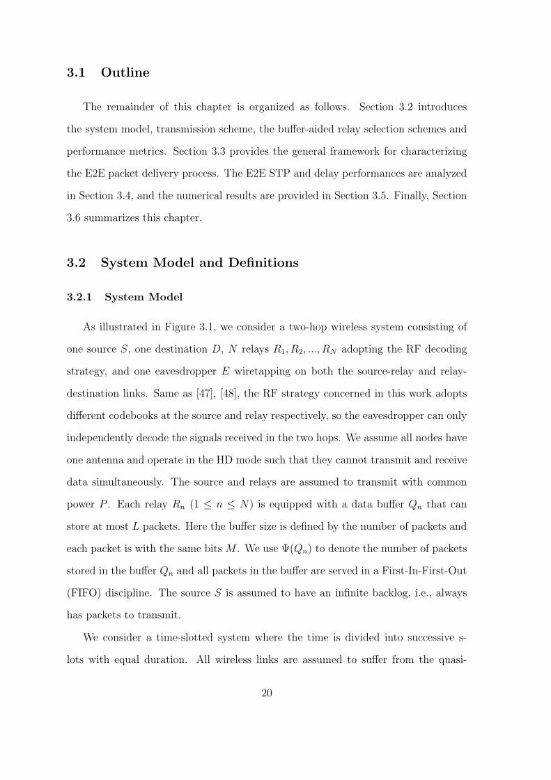
As illustrated in Figure 3.1, we consider a two-hop wireless system consisting of
one source S, one destination D, N relays R1, R2, ..., RN adopting the RF decoding
strategy, and one eavesdropper E wiretapping on both the source-relay and relay-
destination links. Same as [47], [48], the RF strategy concerned in this work adopts
different codebooks at the source and relay respectively, so the eavesdropper can only
independently decode the signals received in the two hops. We assume all nodes have
one antenna and operate in the HD mode such that they cannot transmit and receive
data simultaneously. The source and relays are assumed to transmit with common
power P . Each relay Rn (1 ≤ n ≤ N) is equipped with a data buffer Qn that can
store at most L packets. Here the buffer size is defined by the number of packets and
each packet is with the same bits M . We use Ψ(Qn) to denote the number of packets
stored in the buffer Qn and all packets in the buffer are served in a First-In-First-Out
(FIFO) discipline. The source S is assumed to have an infinite backlog, i.e., always
has packets to transmit.
We consider a time-slotted system where the time is divided into successive s-
lots with equal duration. All wireless links are assumed to suffer from the quasi-
20
Figure 3.1: Illustration of the system model.
static Rayleigh block fading such that the channel gains remain constant during
one time slot, but change independently and randomly from one time slot to the
next. We use |hij|2 to denote the channel gain of the link from node i to node j,
where i ∈ {S,R1, R2, ..., RN} and j ∈ {R1, R2, ..., RN , E,D}. We assume all source-
relay, relay-destination and relay-eavesdropper channel gains are independent and
identically distributed (i.i.d.) with mean E [|hSRn|2] = γsr, E [|hRnD|2] = γrd and
E [|hRnE|2] = γre, respectively. Here, E [·] stands for the expectation operator. The
mean of the source-eavesdropper channel gain is denoted as E [|hSE|2] = γse. In this
work, we assume the instantaneous channel state information (CSI) of legitimate
channels (i.e., |hSRn |2 and |hRnD|2) are always known. Regarding the knowledge of
eavesdropper CSI, we consider two cases, i.e., perfect CSI case where the instanta-
neous eavesdropper CSI (i.e., |hSE|2 and |hRnE|2) are known and partial CSI case
where only the average eavesdropper CSI (i.e., γse and γre) are available. In addition
to fading, all links are also impaired by the additive white Gaussian noise (AWGN)
with variance σ2.
21
3.2.2 Transmission and Buffer-Aided Relay Selection Schemes
In this work, we assume that no direct link is available between the source S and
the destination D, so a relay will be selected to help the S → D transmission. This
work adopts the buffer-aided relay selection scheme that fully exploits the diversity
of relays and buffers. More specifically, we adopt the Max-Ratio buffer-aided relay
selection scheme in [33]. Although this scheme is called relay selection, its principle is
to select the securest link from all individual source-relay and relay-destination links
for transmission in each time slot. Thus, the relay selection is solely determined by
the instantaneous secrecy rate of individual links.
Since we focus on the selection of the securest link from all available individual
links, we adopt the secrecy capacity formulas of an individual link to conduct the
relay selection in this work. Before introducing the relay selection scheme, we first
introduce the selection criterion. Considering an individual link A → B, where A ∈ S
and B ∈ {R1, · · · , Rn} or A ∈ {R1, · · · , Rn} and B ∈ D. The instantaneous secrecy
capacity of link A → B is given by [49]
CABs = max{CAB
m − CAEe , 0}, (3.1)
where
CABm = log
(1 +
P |hAB|2
σ2
), (3.2)
and
CAEe = log
(1 +
P |hAE|2
σ2
), (3.3)
denote the capacities of main channel A → B and eavesdropper channel A → E,
respectively. To transmit a message to B, the transmitter A chooses a rate pair (RABt ,
RABs ) based on the Wyner’s coding scheme [16], where RAB
t denotes the total message
rate and RABs denotes the intended secrecy rate. The rate difference RAB
t − RABs
22

reflects the cost of protecting the message from being intercepted by the eavesdropper
E, which means E cannot decode the message if CAEe < RAB
t −RABs . We use RAB
s
as the selection criterion in the relay selection scheme.
The value of RABs is determined as follows. For a given time slot, if link A → B is
selected for transmission, A uses the knowledge of the main channel CSI to adaptively
adjust RABt arbitrarily close to the instantaneous capacity of the main channel CAB
m
(i.e., RABt = CAB
m ), such that no decoding outage occurs at B. For the setting of
RABs , as the instantaneous eavesdropper CSI is available in the perfect eavesdropper
CSI case, we set RABs = CAB
m − CAEe at A to maximize the intended secrecy rate.
However, only the average eavesdropper CSI is known in the partial eavesdropper
CSI case, so A chooses the secrecy rate RABs = CAB
m − log(1 + PγAE
σ2
)[50]. Notice
that although the conventional approach is to choose a fixed RABs in this case [30–
32], the rationale behind our time-varying RABs is that it can yield a higher secrecy
throughput than the fixed one, as can be seen from the results in [50]. Although our
RABs is varying in each time slot, it can be determined based on the main channel
CSI abstracted from the pilot signal of B [50–52]. In this work, we consider the high
SNR regime, so CABm and RAB
s in the perfect eavesdropper CSI case are approximated
by CABs = RAB
s ≈ log(
|hAB |2|hAE |2
)[50], and the RAB
s in the partial eavesdropper CSI is
approximated as RABs ≈ log
(|hAB |2γAE
)where log is to the base of 2. To inform the
transmitter A when to transmit, we place a threshold ε on the secrecy rate RABs , such
that A can send messages to B if and only if RABs > ε.
Remark: Here we show the differences of several similar terms mentioned above:
the secrecy capacity, the secrecy rate and the target secrecy rate. The secrecy rate
represents the intended transmission rate of a link to securely transmit a message to
the receiver, the secrecy capacity denotes the upper bound of the secrecy rate, and
the target secrecy rate represents the security requirement of the concerned network,
which is a given parameter of the network and is a threshold of the secrecy rate.
23

We are now ready to introduce the Max-Ratio buffer-aided relay selection scheme.
In both eavesdropper CSI cases, the relay with the link that has the maximal intended
secrecy rate will be selected. For the perfect eavesdropper CSI case, the best relay
RPF is selected as
RPF = argmaxRn
max
{|hSRn|2 · 1Ψ(Qn )=L
|hSE|2,|hRnD|2 · 1Ψ(Qn )=0
|hRnE|2
}, (3.4)
where 1Ψ(Qn )=L(1Ψ(Qn )=0) equals 1 if Ψ(Qn) = L (Ψ(Qn) = 0), i.e., relay Rn is
available for source-relay (relay-destination) transmission and equals 0 otherwise. For
the partial eavesdropper CSI case, the best relay RPT is selected as
RPT = argmaxRn
max
{|hSRn |2 · 1Ψ(Qn) =L
γse,|hRnD|2 · 1Ψ(Qn) =0
γre
}. (3.5)
In equations (3.4) and (3.5), the max operation is used to find the maximum of
the channel gain ratios (i.e., the ratio of the main channel gain to the eavesdropper
channel gain) of the available source-relay and relay-destination links for a particular
relay Rn. Thus, the argmax operation, which is operated over all relays, returns the
relay with the link that can yield the maximum channel gain ratio.
From (3.4) and (3.5), we can see that we select the message relay from all available
relays in perfect case according to the instantaneous channel gain ratios of main and
eavesdropper channels, and in the partial case according to the ratios of the instanta-
neous channel gains of main channels and the average channel gains of eavesdropper
channels. With the RF strategy applied at the relays, if the relay Rn is selected
for transmission, the instantaneous secrecy capacity of the buffer-aided relay system
24

when L = 0 is formulated as [48]
Cs =1
2
[min log2
(1 + P |hSRn |2
1 + P |hSE|2,1 + P |hRnD|2
1 + P |hRnE|2
)]+. (3.6)
However, for the general buffer-aided relay system when L > 0, its secrecy capacity
formulation in terms of different SNRs/SINRs is still an open issue. Notice that with
the buffer-aided relay selection scheme concerned in this work, the relay selection in
each time slot is only based on the instantaneous secrecy capacity of each link and
states of all relay buffers. Thus, the secrecy capacity formulation of an individual
link (3.1) is enough for us to derive the main results in this work (see Section IV-A
and Section IV-B for details). It is also worth noting that the buffer-aided relaying
scheme in this work is different from the traditional relaying. In the traditional
relaying, a packet is transmitted to the relay, where it is decoded and forwarded to
the destination in the following time slot. In the relaying scheme of this work, a packet
is first transmitted from the source to a selected relay, where it will be decoded and
stored, and will not be forwarded to the destination until the relay is selected again
for the relay-destination transmission.
3.2.3 Performance Metrics
This chapter aims to investigate the trade-off between the PHY security and
delay performances of the Max-Ratio buffer-aided relay selection scheme. To model
the delay performance of the packet delivery process, we adopt the widely-used end-
to-end (E2E) delay, which is defined as the time slots it takes a packet to reach
its destination after it is generated at the source node. Consider the delivery process
of a tagged packet from S to D via a relay R∗, the E2E delay can be calculated as
the sum of the service time (i.e., the waiting time of the packet at both S and the
head of R∗’s queue before it is transmitted) and the queuing delay (i.e., the time it
25
takes the packet to move from the end to the head of R∗’s queue). Defining Tq as the
queuing delay and Ts (Tr) as the service time at the source node (the head of R∗’s
queue queue), the E2E delay T can be formulated as
T = Ts + Tr + Tq. (3.7)
It is notable that available studies on the PHY security performance study of
buffer-aided relay selection schemes mainly focus on the secrecy outage probability of
a single link, which is defined as the probability that the secrecy outage (i.e., the event
that the instantaneous secrecy capacity Cs is below the target secret rate ε) occurs on
this link [31], [33], [34]. However, such single link-oriented metric may fail to provide
an intuitive insight into the PHY security performance of the whole packet delivery
process. According to the definition of the notion of secure connection probability
in [53], we define a similar a metric called E2E secure transmission probability
(STP) to model the security performance. Focusing again on the delivery process
of the tagged packet from S to D via R∗, the E2E STP is defined as the probability
that neither the S → R∗ nor R∗ → D delivery suffers from secrecy outage. Based
on the formulation of the secure connection probability in [53], we formulate the E2E
STP as
pst = P(CSR∗s ≥ ε, CR∗D
s ≥ ε), (3.8)
where CSR∗s (CR∗D
s ) denotes the instantaneous secrecy capacity of the S → R∗ (R∗ →
D) link, and CSR∗s ≥ ε (CR∗D
s ≥ ε) represents the event that the S → R∗ (R∗ → D)
link is selected and secure transmission is conducted when the tagged packet is at S
(the head of R∗’s queue) and ε is the target secrecy rate.
26

Figure 3.2: End-to-end delivery process of a packet.
3.3 General Framework for E2E Packet Delivery Process Mod-
eling
In this section, we introduce our general framework for characterizing the E2E
packet delivery process under both perfect and partial eavesdropper CSI cases, in-
cluding the source-relay delivery process, buffer queuing process and relay-destination
delivery process, as illustrated in Figure 3.2. To facilitate the introduction of the
framework, we focus again on the delivery process of a tagged packet from S to D
via a relay R∗.
For the modeling of source-relay (resp. relay-destination) delivery process, we
first develop a Markov chain to model the transition of possible buffer states when
the tagged packet is at S (resp. the head of R∗’s queue). Based on the absorbing
Markov chain theory, we then determine the corresponding stationary probability
distribution, such that the probability of each possible buffer state can be obtained.
For the modeling of buffer queuing process, we regard the queues of all relays as
a single queue and the resultant Markov chain is equivalent to a Bernoulli process.
Notice that the buffer queuing process is relatively simple in our framework, and thus
we focus on the modeling of the source-relay and relay-destination delivery processes
of the tagged packet in this section.
27

µPF(s) =
N1(s)∑n1=0
(N1(s)
n1
)(−1)n1
α
2εn1 + α
(2ε
β + 2ε
)N2(s)
, (3.9)
νPF(s) =
N1(s)∑n1=0
(N1(s)
n1
)(−1)n1 (3.10)
[n1 · 2F1
(N2(s), N2(s) + 1;N2(s) + 2; n1β−α
β(α+2εn1)
)(N2(s) + 1)(α + 2εn1)
(4εα
2εn1β + αβ)
)N2(s)
−2F1
(N2(s), N2(s) + 1;N2(s) + 2; 1− α
n1β
)N2(s) + 1
(α
n1β
)N2(s)],
µPT(s) =[1− e−2ε/α
]N1(s) [1− e−2ε/β
]N2(s), (3.11)
νPT(s) =
N2(s)∑n2=0
N1(s)−1∑n1=0
(N2(s)
n2
)(N1(s)− 1
n1
)(−1)n2+n1
N1(s)βe− (αn2+β+βn1)2
ε
αβ
αn2 + β + βn1
.(3.12)
3.3.1 Source-Relay Delivery Process Modeling
This subsection derives the stationary probability distribution for the source-relay
delivery under both perfect and partial eavesdropper CSI cases. We first define the
possible buffer states for the source-relay delivery. As the network contains N relays
and each relay has a buffer of size L, there are (L + 1)N possible states in total.
Defining si the i-th(i ∈ {1, 2, · · · , (L+ 1)N}
)state, we can represent si by
si = [Ψsi(Q1), · · · ,Ψsi(Qn), · · · ,Ψsi(QN)]T , n ∈ {1, 2, · · · , N}, (3.13)
where Ψsi(Qn) ∈ [0, L] gives the number of packets in buffer Qn at state si. We can see
that each buffer state si can determine a pair (N1(si), N2(si)), where N1(si) ∈ [0, N ]
and N2(si) ∈ [0, N ] denote the number of available (i.e., Ψsi(Qn) = L) source-relay
links and available (i.e., Ψsi(Qn) = 0) relay-destination links at state si, respectively.
28

Next, we determine the state transition matrix. Suppose that the buffers are in
state si at time slot t. According to the relay selection scheme in Section 3.2.2, one
link will be selected from the available source-relay and relay-destination links for
transmission at this time slot. Thus, the buffer state may move from si to several
possible states at the next time slot, forming a Markov chain. We define A the
(L + 1)N × (L + 1)N state transition matrix, where the (i, j)-th entry ai,j = P(sj|si)
denotes the transition probability that the buffer state moves from si to sj. According
to the transmission scheme in Section 3.2.2, the state transition happens if and only
if a successful transmission is conducted on the selected link (i.e., Rs ≥ ε). We
use S+i (S−
i ) to denote the set of states si can move to when a successful source-relay
(relay-destination) transmission is conducted. Now, we are ready to give the following
lemma regarding the state transition matrix A.
Lemma 1 Suppose that the buffers are in state si at time slot t, the (i, j)-th entry
of the state transition matrix A under both the perfect and partial eavesdropper CSI
cases is given by
ai,j =
µ∆(si), if sj = si,
ν∆(si)
N1(si), if sj ∈ S+
i ,
1− µ∆(si)− ν∆(si)
N2(si), if sj ∈ S−
i ,
0, elsewhere.
(3.14)
where ∆ ∈ {PF = perfect,PT = partial} denotes the eavesdropper CSI case, and
µ∆(si) and ν∆(si) are given in (3.9) and (3.10) for the perfect CSI case and in (3.11)
and (3.12) for the partial CSI case with the parameter s = si.
Proof 1 See Appendix A.1 for the proof.
From Lemma 1, we can see that ai,j = 0 and(L+1)N∑j=1
ai,j = 1, which means that
the Markov chain can move to any state sj(j ∈ {1, 2, · · · , (L+ 1)N}
)from a starting
29
state si with a non-zero probability, i.e., the Markov chain is irreducible [54]. We can
also see from Lemma 1 that ai,i = 0, which means that the Markov chain can return to
state si in one time slot, i.e., the period of si equals 1. This proves that every state si is
aperiodic and thus the Markov chain is aperiodic [54]. According to Definition 1 and
Theorem 2 of Chapter 11 in [55], the irreducibility and aperiodicity properties ensure
that our Markov chain that models the buffer states of the source-relay transmission
process is stationary and there exists a unique stationary probability distribution
π = [π∆s1, · · · , π∆
si, · · · , π∆
s(L+1)N
]T such that Aπ = π and(L+1)N∑
i=1
π∆si
= 1, where π∆si
denotes the stationary probability of state si.
According to Lemma 2 in [54], the analytical expression of π∆sican be given by
π∆si=
(L+1)N∑j=1
∏si′∈Ξ(si,Θsj )
ai,i′∏sj′∈Ξ(sj ,Θsi )
aj,j′
−1
, (3.15)
where Θsi (Θsj) denotes the set of states that have the same stationary probability
as si (sj) has, and Ξ(si,Θsj) (Ξ(sj,Θsi) ) denotes the set of states that state si (sj)
has to pass through to reach a state in Θsj (Θsi).
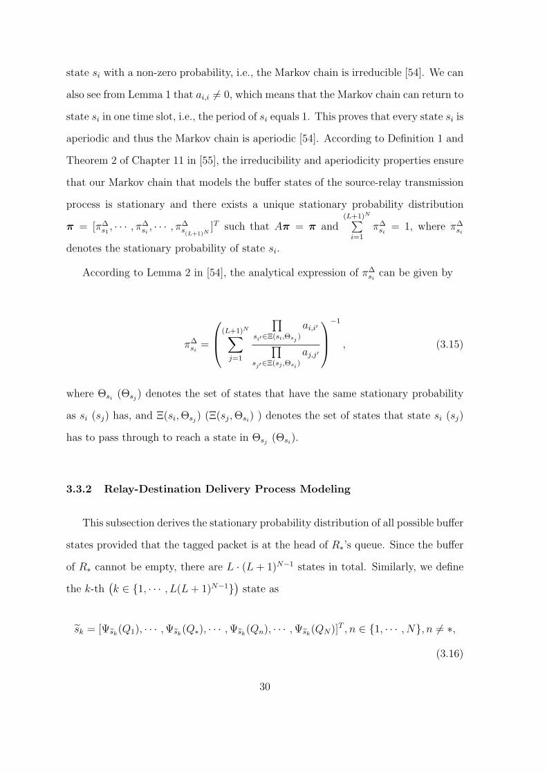
3.3.2 Relay-Destination Delivery Process Modeling
This subsection derives the stationary probability distribution of all possible buffer
states provided that the tagged packet is at the head of R∗’s queue. Since the buffer
of R∗ cannot be empty, there are L · (L + 1)N−1 states in total. Similarly, we define
the k-th(k ∈ {1, · · · , L(L+ 1)N−1}
)state as
sk = [Ψsk(Q1), · · · ,Ψsk(Q∗), · · · ,Ψsk(Qn), · · · ,Ψsk(QN)]T , n ∈ {1, · · · , N}, n = ∗,
(3.16)
30

where Ψsk(Qn) and Ψsk(Q∗) represent the number of packets in the buffers of Rn and
R∗ at state sk respectively. It’s obvious that 0 ≤ Ψsk(Qn) ≤ L and 1 ≤ Ψsk(Q∗) ≤ L,
and every state sk corresponds to one pair (N1(sk), N2(sk)), where N1(sk) and N2(sk)
denote the numbers of available source-relay and relay-destination links at state sk,
respectively.
We denote A as the L(L+1)N−1×L(L+1)N−1 state transition matrix of all states
sk, where the (k, l)-th entry ak,l = P(sl|sk) is the transition probability that the state
moves from sk to sl. Similarly, we use S+k (S−
k ) to denote the set of states sk can
move to when a successful source-relay (relay-destination) transmission is conducted.
Notice that the buffer state can move from sk into S−k only when a successful relay-
destination transmission except for R∗ → D occurs. Based on the above definitions,
we give the following lemma regarding the state transition matrix A.
Lemma 2 Suppose that the buffers are in state sk when the tagged packet is at the
head of relay R∗’s queue, the (k, l)-th entry of the state transition matrix A under
both the perfect and partial eavesdropper CSI cases is given by
ak,l =
µ∆(sk), if sl = sk,
ν∆(sk)
N1(sk), if sl ∈ S+
k ,
1− µ∆(sk)− ν∆(sk)
N2(sk)− 1, if sl ∈ S−
k ,
0, elsewhere.
(3.17)
where ∆ ∈ {PF = perfect,PT = partial} denotes the eavesdropper CSI case, µ∆(sk)
and ν∆(sk) are given in (3.9) and (3.10) for the perfect CSI case and in (3.11) and
(3.12) for the partial CSI case.
Proof 2 The proof is same as that for Lemma 1, so we have omitted it here.
Similarly, according to [55], we can see from Lemma 2 that our Markov chain
31

ϕ(s) =
N1(s)∑n1=0
N2(s)∑n2=0
(N1(s)
n1
)(N2(s)
n2
)(−1)n1+n2
αβ
2ε(n1β + n2α) + αβ, (3.19)
ω(s) =
N1(s)∑n1=0
N2(s)−1∑n2=0
(N1(s)n1
)(N2(s)−1
n2
)(−1)n1+n2N2(s)α
2β
2ε(n1β + α + n2α)2 + αβ(n1β + α + n2α). (3.20)
that models the buffer states of the relay-destination transmission process is also
stationary. We use π = [π∆s1, · · · , π∆
sk, · · · , π∆
sL(L+1)N−1
]T to denote the corresponding
stationary probability distribution when the tagged packet is at the head of R∗’s
queue, where π∆sk
denotes the stationary probability of state sk. Based on the state
transition matrix A and Lemma 2 in [54], we can determine the analytical expression
of the stationary probability of state sk in π as
π∆sk
=
(L+1)N∑l=1
∏sk′∈Ξ(sk,Θsl
)
ak,k′∏sl′∈Ξ(sl,Θsk
)
al,l′
−1
, (3.18)
where Θsk (Θsl) denotes the set of states that have the same stationary probability
as sk (sl) has, and Ξ(sk,Θsl) (Ξ(sl,Θsk) ) denotes the set of states that state sk (sl)
has to pass through to reach a state in Θsl (Θsk).
3.4 E2E STP and Delay Analysis
With the help of the stationary probability distributions in Section 3.3, this section
provides theoretical analysis for the E2E STP and delay performances under both the
perfect and partial eavesdropper CSI cases.
32
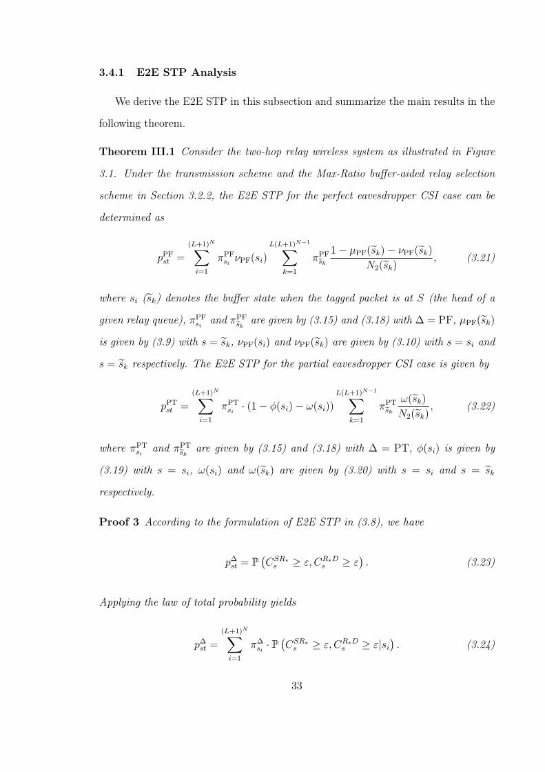
3.4.1 E2E STP Analysis
We derive the E2E STP in this subsection and summarize the main results in the
following theorem.
Theorem III.1 Consider the two-hop relay wireless system as illustrated in Figure
3.1. Under the transmission scheme and the Max-Ratio buffer-aided relay selection
scheme in Section 3.2.2, the E2E STP for the perfect eavesdropper CSI case can be
determined as
pPFst =
(L+1)N∑i=1
πPFsi
νPF(si)
L(L+1)N−1∑k=1
πPFsk
1− µPF(sk)− νPF(sk)
N2(sk), (3.21)
where si (sk) denotes the buffer state when the tagged packet is at S (the head of a
given relay queue), πPFsi
and πPFsk
are given by (3.15) and (3.18) with ∆ = PF, µPF(sk)
is given by (3.9) with s = sk, νPF(si) and νPF(sk) are given by (3.10) with s = si and
s = sk respectively. The E2E STP for the partial eavesdropper CSI case is given by
pPTst =
(L+1)N∑i=1
πPTsi
· (1− ϕ(si)− ω(si))
L(L+1)N−1∑k=1
πPTsk
ω(sk)
N2(sk), (3.22)
where πPTsi
and πPTsk
are given by (3.15) and (3.18) with ∆ = PT, ϕ(si) is given by
(3.19) with s = si, ω(si) and ω(sk) are given by (3.20) with s = si and s = sk
respectively.
Proof 3 According to the formulation of E2E STP in (3.8), we have
p∆st = P(CSR∗
s ≥ ε, CR∗Ds ≥ ε
). (3.23)
Applying the law of total probability yields
p∆st =
(L+1)N∑i=1
π∆si· P
(CSR∗
s ≥ ε, CR∗Ds ≥ ε|si
). (3.24)
33

We define R∗ = Rn, n ∈ N1 the event that relay Rn is selected for the source-relay
delivery at buffer state si, where N1 = {n|Ψsi(Qn) = L} denotes the index set of
available relays. Obviously, |N1| = N1(si). Again, applying the law of total probability,
we have
p∆st =
(L+1)N∑i=1
π∆si·∑n∈N1
P(CSR∗
s ≥ ε, CR∗Ds ≥ ε,R∗ = Rn|si
).
(3.25)
After changing the above probability into conditional probability, we have
p∆st =
(L+1)N∑i=1
π∆si·∑k∈N1
P(CSR∗
s ≥ ε,R∗ = Rn|si)
·P(CR∗D
s ≥ ε|CSRns ≥ ε,R∗ = Rn, si
)(3.26)
=
(L+1)N∑i=1
π∆si·∑n∈N1
P(CSRn
s ≥ ε|si)P(CRnD
s ≥ ε),
(3.27)
where (3.27) follows since the relay-destination delivery is independent of the buffer
state and transmission in the first hop provided R∗ = Rn. Notice that P(CSRn
s ≥ ε|si)
is the probability the link S → Rn is selected and the transmission is secure at state
si when the tagged packet is at S, and P(CRnD
s ≥ ε)represents the probability that
the link Rn → D is selected and the transmission is secure when the tagged packet is
at the head of Rn’s queue.
For the perfect eavesdropper CSI case, it is easy to see CSR∗s = RSR∗
s and P(CSRn
s ≥ ε|si)
is equivalent to the transition probability ai,j from si to sj for sj ∈ S+i . Thus, we have
P(CSRn
s ≥ ε|si)=
νPF(si)
N1(si), (3.28)
34

according to Lemma 1. Next, applying the law of total probability, we have
P(CRnD
s ≥ ε)=
L(L+1)N−1∑k=1
πPFsk
· P(CRnD
s ≥ ε|sk). (3.29)
Since CRnDs = RRnD
s , we have
P(CRnD
s ≥ ε|sk)= P
(RRnD
s ≥ ε|sk)
(3.30)
=1− µPF(sk)− νPF(sk)
N2(sk), (3.31)
where (3.31) follows from the proof of Lemma 2. Finally, the E2E STP for the
perfect eavesdropper CSI case follows after substituting (3.31) into (3.29), and then
substituting (3.29) and (3.28) into (3.27).
For the partial eavesdropper CSI case, based on the random variables X′and Y
′
in Appendix A.1, P(CSRn
s ≥ ε|si)is equivalent to
1
N1(si)P(max{X ′
, Y′}
U≥ 2ε, X
′> Y
′)
(3.32)
=1
N1(si)
(1− E[FX′(2εU)FY ′(2εU)]− EU
[ ∫ ∞
2εU
P(X ′< y)fY ′ (y)dy
]), (3.33)
where fU(u) = e−u, ua,b =|ha,b|2γab
, a, b ∈ {SRn, SE,RnD,RnE} and the first expecta-
tion in (3.33) is equivalent to
P(max{X ′
, Y′}
U< 2ε
), (3.34)
which can be given by the ϕ(si) in (3.19) with s = si, and the second expectation in
(3.33) is equivalent to
P(max{X ′
, Y′}
U≥ 2ε, X
′< Y
′), (3.35)
35

which can be given by the ω(si) in (3.20) with s = si. Thus, we have
P(CSRn
s ≥ ε|si)=
1− ϕ(si)− ω(si)
N1(si), (3.36)
and
P(CRnD
s ≥ ε|si)=
P(
max{X′,Y
′}U
≥ 2ε, X′< Y
′)
N2(si)
=ω(si)
N2(si). (3.37)
Following the same idea, we have
P(CRnD
s ≥ ε|sk)=
ω(sk)
N2(sk), (3.38)
and thus
P(CRnD
s ≥ ε)=
L(L+1)N−1∑k=1
πPTsk
ω(sk)
N2(sk). (3.39)
Finally, substituting (3.36) and (3.39) into (3.27) yields the E2E STP for the partial
eavesdropper CSI case.
3.4.2 E2E Delay Analysis
This subsection presents the analytical results for the E2E delay of the system
under both the perfect and partial eavesdropper CSI cases. We first derive the mean
service time of the tagged packet at the source and at the head of some relay R∗’s
queue, and then derive the expected queuing delay of the tagged packet at relay
R∗. Combining the mean service time and the expected queuing delay, we finally
determine the expected E2E delay. We first establish the following lemma regarding
the mean service time.
36
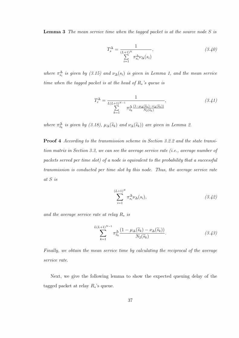
Lemma 3 The mean service time when the tagged packet is at the source node S is
T∆s =
1(L+1)N∑
i=1
π∆siν∆(si)
, (3.40)
where π∆si
is given by (3.15) and ν∆(si) is given in Lemma 1, and the mean service
time when the tagged packet is at the head of R∗’s queue is
T∆r =
1L(L+1)N−1∑
k=1
π∆sk
(1−µ∆(sk)−ν∆(sk))N2(sk)
, (3.41)
where π∆sk
is given by (3.18), µ∆(sk) and ν∆(sk)) are given in Lemma 2.
Proof 4 According to the transmission scheme in Section 3.2.2 and the state transi-
tion matrix in Section 3.3, we can see the average service rate (i.e., average number of
packets served per time slot) of a node is equivalent to the probability that a successful
transmission is conducted per time slot by this node. Thus, the average service rate
at S is
(L+1)N∑i=1
π∆siν∆(si), (3.42)
and the average service rate at relay R∗ is
L(L+1)N−1∑k=1
π∆sk
(1− µ∆(sk)− ν∆(sk))
N2(sk). (3.43)
Finally, we obtain the mean service time by calculating the reciprocal of the average
service rate.
Next, we give the following lemma to show the expected queuing delay of the
tagged packet at relay R∗’s queue.
37

Lemma 4 The expected queuing delay of the tagged packet at relay R∗’s queue is
T∆q =
(L+1)N∑i=1
N∑n=1
π∆siΨsi(Qn)
N(L+1)N∑
i=1
π∆siν∆(si)
, (3.44)
where π∆si
is given by (3.15), ν∆(si) is given in Lemma 1.
Proof 5 Based on the general framework in Section 3.3, we model the queues of all
relays as a single Bernoulli queue. According to Little’s Law [56], the expected queuing
delay for this queue is
T∆,totalq =
E[
N∑n=1
Ψ(Qn)
]rarr
, (3.45)
where the numerator and the denominator denote the expected queuing length and
average arrival rate of relay, respectively. Considering all available buffer states, we
can derive the expected queuing length as
E
[N∑k=1
Ψ(Qn)
]=
(L+1)N∑i=1
N∑n=1
π∆siΨsi(Qn). (3.46)
Notice the arrival rate is equivalent to the service rate of S. Based on Lemma 3, we
have
(L+1)N∑i=1
π∆siν∆(si). (3.47)
Thus, the total average queuing delay of all relays is
T∆,totalq =
(L+1)N∑i=1
N∑n=1
π∆siΨsi(Qn)
(L+1)N∑i=1
π∆siν∆(si)
. (3.48)
38
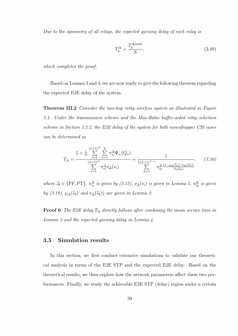
Due to the symmetry of all relays, the expected queuing delay of each relay is
T∆q =
T∆,totalq
N, (3.49)
which completes the proof.
Based on Lemma 3 and 4, we are now ready to give the following theorem regarding
the expected E2E delay of the system.
Theorem III.2 Consider the two-hop relay wireless system as illustrated in Figure
3.1. Under the transmission scheme and the Max-Ratio buffer-aided relay selection
scheme in Section 3.2.2, the E2E delay of the system for both eavesdropper CSI cases
can be determined as
T∆ =
1 + 1N
(L+1)N∑i=1
N∑n=1
π∆siΨsi(Qn)
(L+1)N∑i=1
π∆siν∆(si)
+1
L(L+1)N−1∑k=1
π∆sk
(1−µ∆(sk)−ν∆(sk))N2(sk)
, (3.50)
where ∆ ∈ {PF,PT}, π∆siis given by (3.15), ν∆(si) is given in Lemma 1, π∆
skis given
by (3.18), µ∆(sk) and ν∆(sk)) are given in Lemma 2.
Proof 6 The E2E delay T∆ directly follows after combining the mean service time in
Lemma 3 and the expected queuing delay in Lemma 4.
3.5 Simulation results
In this section, we first conduct extensive simulations to validate our theoreti-
cal analysis in terms of the E2E STP and the expected E2E delay. Based on the
theoretical results, we then explore how the network parameters affect these two per-
formances. Finally, we study the achievable E2E STP (delay) region under a certain
39
E2E delay (STP) constraint to illustrate the trade-off between the PHY security and
delay performances.
3.5.1 Simulation Settings
To validate our theoretical results for the E2E STP and expected E2E delay, a
dedicated C++ simulator was developed to simulate the E2E packet delivery process
based on the Max-Ratio buffer aided relay selection schemes in (3.4) and (3.5), which
is now available at [57]. With the help of the simulator, we conduct extensive sim-
ulations to calculate the simulated results of E2E STP and expected E2E delay. In
all simulations, the total number of time slots is fixed as 105 and the corresponding
relay selection scheme is performed once per slot for each eavesdropper CSI case.
The simulated E2E STP is calculated as the ratio of the number of packets securely
transmitted to the destination D to the total number of packets generated at the
source S, i.e.,
pst =number of packets securely transmitted to D
number of packets generated.
The expected E2E delay is calculated as the ratio of the total E2E delay (measured
in time slots) of all packets transmitted to D to the number of these packets, i.e.,
T =total E2E delay of packets transmitted to D
number of packets transmitted to D.
Please notice that the metric T accounts for all packets in both eavesdropper CSI
cases, but the meaning of “all packets” differs. In the partial CSI case, “all packets”
refers to not only the securely transmitted packets but also the non-securely trans-
mitted ones. In the perfect CSI case, “all packets” refers to the securely transmitted
packets, because all packets can be securely transmitted.
Similar to the settings in [54], we set the noise variance as σ2 = 1, the trans-
40

mission power as P = 20, and the average channel gains of the source-relay and
relay-destination links as γsr = γrd = 5dB. Thus, the corresponding average SNR
high enough to guarantee successful decoding at the relays and the destination. We
set the channel gain ratio α and β as α = β = 2 and the average eavesdropping chan-
nel gains as γse =γsrα
and γre =γrdβ. Notice that simulations with other parameters
can also be conducted with our simulator.
3.5.2 Model Validation
We first conduct simulations for various settings of the target secrecy rate ε under
the network scenario of N = 5 and L = 5. The corresponding simulated and theoret-
ical results of the E2E STP p∆st (∆ = {PF,PT}) are summarized in Figure 3.3a, and
the results of expected E2E delay T∆ are summarized in Figure 3.1, for both perfect
and partial eavesdropper CSI cases. We then fix the buffer size as L = 2 and target
secrecy rate as ε = 1, and conduct simulations by varying the number of relays N .
We provide plots in Figure 3.4a for the simulated and theoretical results of p∆st and
in Figure 3.4b for the results of T∆, under both eavesdropper CSI cases. Finally, we
consider a fixed number of relays N = 2 and a given target secrecy rate ε = 1. For
this scenario, simulations under various settings of buffer size L are conducted, and
the simulated/theoretical results of p∆st and T∆ are shown in Figure 3.5a and Figure
3.5b, respectively.
We can see from Figure 3.3a, Figure 3.4a and Figure 3.5a, the simulation results
of p∆st match nicely with the theoretical ones for both eavesdropper CSI cases under
various network settings. This indicates that our theoretical analysis can be used to
efficiently model the E2E STP of the system. For T∆, it can be seen from Figure
3.3b, Figure 3.4b and Figure 3.5b that all simulation results match proficiently with
the corresponding theoretical curves, implying that our theoretical analysis is highly
efficient for the E2E delay modeling of the system.
41
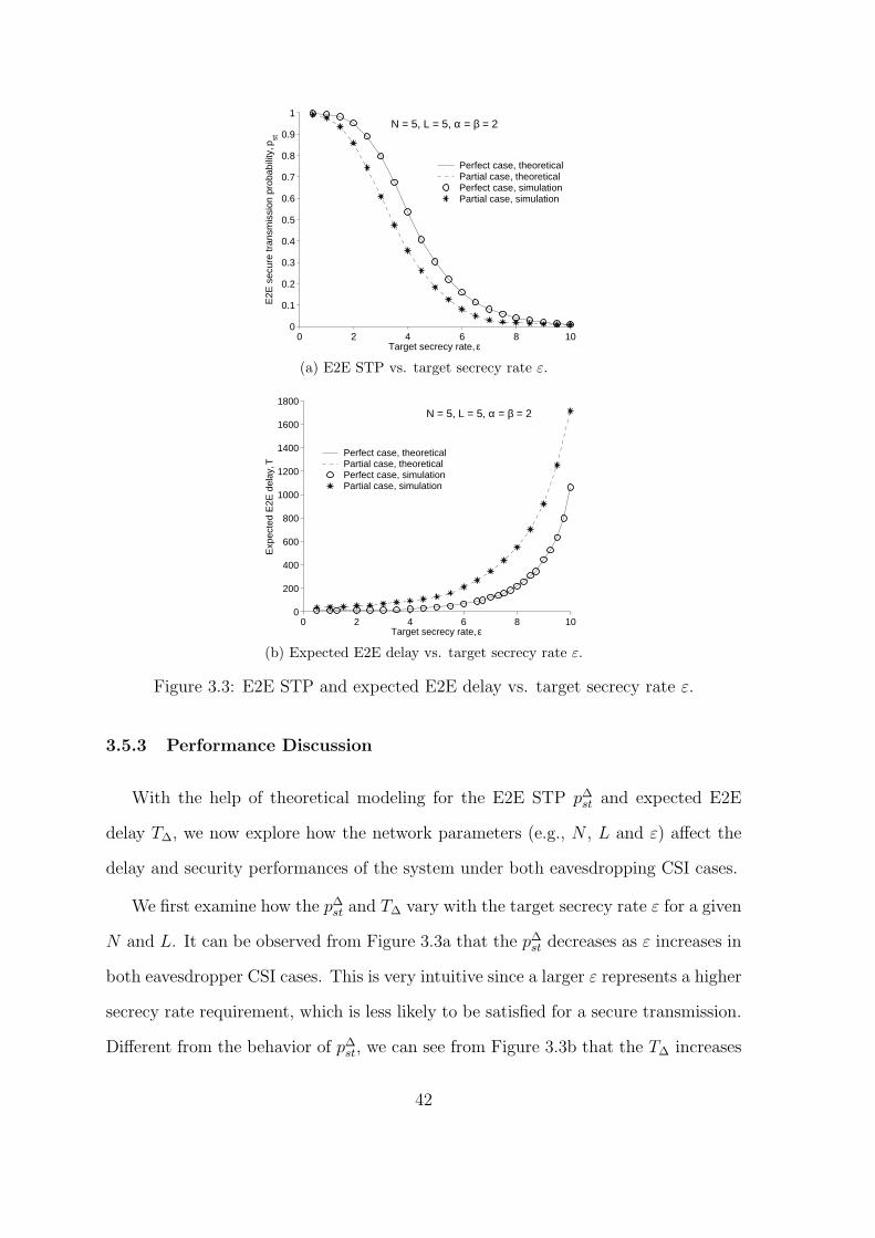
0 2 4 6 8 100
0.1
0.2
0.3
0.4
0.5
0.6
0.7
0.8
0.9
1
Target secrecy rate, ε
E2E
sec
ure
tran
smis
sion
pro
babi
lity,
pst
Perfect case, theoreticalPartial case, theoreticalPerfect case, simulationPartial case, simulation
N = 5, L = 5, α = β = 2
(a) E2E STP vs. target secrecy rate ε.
0 2 4 6 8 100
200
400
600
800
1000
1200
1400
1600
1800
Target secrecy rate, ε
Exp
ecte
d E
2E d
elay
, T
Perfect case, theoreticalPartial case, theoreticalPerfect case, simulationPartial case, simulation
N = 5, L = 5, α = β = 2
(b) Expected E2E delay vs. target secrecy rate ε.
Figure 3.3: E2E STP and expected E2E delay vs. target secrecy rate ε.
3.5.3 Performance Discussion
With the help of theoretical modeling for the E2E STP p∆st and expected E2E
delay T∆, we now explore how the network parameters (e.g., N , L and ε) affect the
delay and security performances of the system under both eavesdropping CSI cases.
We first examine how the p∆st and T∆ vary with the target secrecy rate ε for a given
N and L. It can be observed from Figure 3.3a that the p∆st decreases as ε increases in
both eavesdropper CSI cases. This is very intuitive since a larger ε represents a higher
secrecy rate requirement, which is less likely to be satisfied for a secure transmission.
Different from the behavior of p∆st, we can see from Figure 3.3b that the T∆ increases
42

as ε increases in both cases. According to the transmission schemes in Section 3.2.2, a
larger ε results in a reduced successful transmission probability in each hop and thus
a reduced service rate, as can be seen from Lemma 3. The reduction in service rate
leads to not only an increased service time but also an increased queuing delay since
a packet in the relay queue has to wait for a longer time before the service process of
all the packets ahead of it is finished. Another observation from both figures indicates
that the relay selection scheme in the perfect eavesdropper CSI case has consistently
better STP and delay performances than that in the partial CSI case. Based on the
relay selection criteria in (3.4) and (3.5), a link with a larger instantaneous secrecy
rate (or secrecy capacity) can be selected in the perfect eavesdropper CSI, which thus
yields a larger successful transmission probability (or secure transmission probability)
in each hop for a given target secrecy rate ε. Thus, the relay selection scheme in the
perfect eavesdropper CSI outperforms that in the partial case in terms of the E2E
STP and E2E expected delay.
Next we investigate the impact of number of relays N on the p∆st and T∆ for given
ε and L. Figure 3.4 illustrates how p∆st and T∆ vary with N for the setting of L = 2,
α = β = 2 and ε = 1. We can see from Figure 3.4a that the E2E STP increases
as the number of relays N increases for both eavesdropper CSI cases. Notice that
the affect of distributing more relays in the system on the E2E STP performance
is two-edged. First, it leads to a link with a larger instantaneous secrecy capacity
selected by the relay selection schemes, so the STP in the first hop increases. Second,
however, the number of available relay-destination links competing for transmission
increases, which may result in a decreased STP in the second hop. Actually, the
increasing behavior the STP in the first hop dominates the whole behavior of the
E2E STP, and thus the E2E STP increases as N increases. Similar to the E2E
STP, it can be observed from Figure 3.4b that the expected E2E delay increases as
the number of relays N increases simultaneously. This is also due to the two-edged
43

0 5 10 150.3
0.4
0.5
0.6
0.7
0.8
0.9
1
Numbe of relays, N
E2E
sec
ure
tran
smis
sion
pro
babi
lity,
pst
Perfect case, theoreticalPartial case, theoreticalPerfect case, simulationPartial case, simulation
L = 2, α = β = 2, ε = 1
(a) E2E STP vs. number of relays N .
0 5 10 154
6
8
10
12
14
16
18
Number of relays, N
Exp
ecte
d E
2E d
elay
, T (
slot
s/pa
cket
)
Perfect case, theoreticalPartial case, theoreticalPerfect case, simulationPartial case, simulation
L = 2, α = β = 2, ε = 1
(b) Expected E2E delay vs. number of relays N .
Figure 3.4: E2E STP and expected E2E delay vs. number of relays N .
impact of distributing more relays, which reduces the mean service time in the first
hop, while increasing the average queuing delay and mean service time in the second
hop. However, the latter impact is dominant, resulting in the increasing behavior of
T∆ vs. N .
Finally, we examine how the p∆st and T∆ vary with the buffer size L for a fixed
setting of ε and N , as illustrated in Figure 3.5. As can be seen from Figure 3.5 that,
both the E2E STP and expected E2E delay increase as the buffer size L increases
under both eavesdropper CSI cases, which is due to the similar reason of distributing
more relays. Another observation from Figure 3.5a indicates that as the buffer size
44

0 5 10 150.35
0.4
0.45
0.5
0.55
0.6
0.65
0.7
Buffer size, L
E2E
sec
ure
tran
smis
sion
pro
babi
lity,
pst
Perfect case, theoreticalPartial case, theoreticalPerfect case, simulationPartial case, simulation
N = 2, α = β = 2, ε = 1
(a) E2E STP vs. buffer size L.
0 5 10 150
20
40
60
80
100
120
140
160
180
Buffer size, L
Exp
ecte
d E
2E d
elay
, T (
slot
s/pa
cket
)
Perfect case, theoreticalPartial case, theoreticalPerfect case, simulationPartial case, simulation
N = 2, α = β = 2, ε = 1
(b) Expected E2E delay vs. buffer size L.
Figure 3.5: E2E STP and expected E2E delay vs. buffer size L.
increases above a certain value, for example, L = 5 in Figure 3.5a, the E2E STP
stays almost constant. This is because that almost all the source-relay and relay-
destination links of all relays are available for relay selection, so the instantaneous
secrecy capacity of the selected link can hardly be improved.
3.5.4 Security-Delay Trade-Off Analysis
Based on the theoretical results of p∆st and T∆, we now investigate the trade-offs
between the E2E STP and expected E2E delay of the concerned system with the
Max-Ratio buffer aided relay selection schemes.
45

4 6 8 10 12 14 16 18 200.3
0.4
0.5
0.6
0.7
0.8
0.9
1
E2E delay constraint, τ (slots/packet)
E2E
sec
ure
tran
smis
sion
pro
babi
lity,
pst
17 18 19 200.991
0.992
0.993
0.994
N = 1
N = 1
N = 4
N = 6N = 7
N = 9 N = 10 N = 12
N = 14 N = 16
N = 16 N = 17
N = 18
N = 6N = 10 N = 12 N = 13 N = 15 N = 16 N = 17 N = 18
L = 2, α = β = 2, ε = 1
Perfect case
Partial case
(a) Maximum achievable E2E STP for varying N .
4 6 8 10 12 14 16 18 200.3
0.35
0.4
0.45
0.5
0.55
0.6
0.65
E2E delay constraint, τ (slots/packet)
E2E
sec
ure
tran
smis
sion
pro
babi
lity,
pst
L = 1
L = 1
L = 2
L = 3L = 4
L = 5 L = 6
L = 2 L = 3 L = 4
N = 2, α = β = 2, ε = 1
Perfect case
Partial case
(b) Maximum achievable E2E STP for varying L.
Figure 3.6: Maximum achievable E2E STP vs. E2E delay constraint τ .
First, we study the achievable E2E STP region under a given constraint on the
expected E2E delay in both eavesdropper CSI cases. For the scenario of α = β = 2 and
ε = 1, Figure 3.6a (resp. Figure 3.6b) illustrates the maximum E2E STP p∆st achieved
by the optimal number of relays N (resp. buffer size L) under various expected E2E
delay constraints τ for a fixed setting of L = 2 (resp. N = 2). It can be seen from
Figure 3.6a and Figure 3.6b that, as τ increases, the maximum achievable E2E STP
increases in both cases, which implies that relaxing the delay constraint can achieve
a larger STP region accordingly. This clearly shows the trade-off between the PHY
security and delay performances of the system. Another observation from Figure
46
3.6a (resp. Figure 3.6b) shows that the maximum achievable E2E STP is a piecewise
function of τ and an optimal N (resp. L) can apply to a small range of τ .
A further careful observation from Figure 3.6 indicates that, as τ scales up, the
maximum achievable E2E STP with respect to L in Figure 3.6b becomes less sensitive
to the variation of τ (i.e., as τ scales up an optimal L can apply to a wider range of
τ), while this is not the case for the maximum achievable E2E STP with respect to N
in Figure 3.6a. For example, under the perfect eavesdropper CSI case, as τ increases
from 18 to 20, the maximum STP in Figure 3.6b remains unchanged while that in
Figure 3.6a increases from 0.9917 to 0.9934. Under the partial eavesdropper CSI case,
a similar observation can be found as τ increases from 16 to 18. Thus, compared to
the maximum STP achieved by optimal L, the maximum STP achieved by optimal
N depends more heavily on the variation of the delay constraint τ .
Next, we explore the achievable expected E2E delay region under a given E2E STP
constraint under both eavesdropper CSI cases. For the same scenario of α = β = 2
and ε = 1, we show in Figure 3.7a (resp. Figure 3.7b) the minimum expected E2E
delay achieved by the optimal number of relays N (resp. buffer size L) under various
E2E STP constraints ρ for a fixed setting of L = 2 (resp. N = 2). We can see from
Figure 3.7a and Figure 3.7b that, as ρ increases, the minimum achievable expected
E2E delay increases in both cases. This suggests that imposing a more stringent
security constraint on the E2E packet delivery leads to a smaller delay region, which
also illustrates a clear trade-off between the PHY security and delay performances.
It can also be observed from Figure 3.7a and Figure 3.7b that all the curves are
truncated at a certain point of ρ (say threshold), i.e., the minimum expected E2E
delay becomes indeterminable, as ρ increases above this threshold. For example, this
threshold is about 1 (0.99) for the perfect (partial) CSI case in Figure 3.7a and about
0.7 (0.558) for the perfect (partial) CSI case in Figure 3.7b. This is because that,
under the fixed setting of α = β = 2 and ε = 1, the E2E STP of each case finally
47
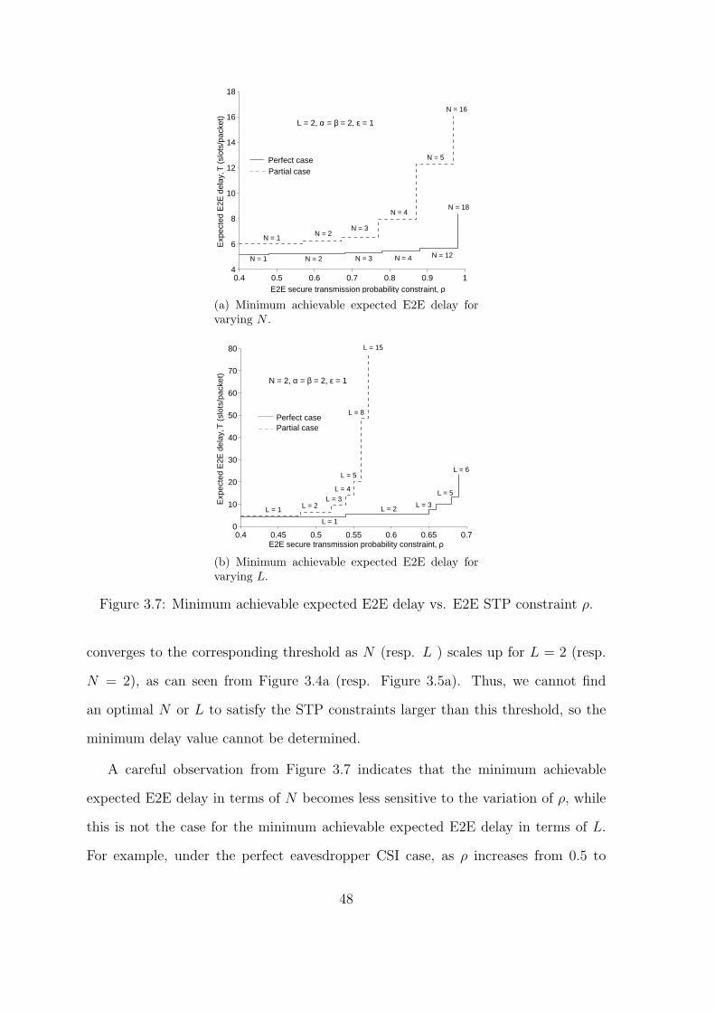
0.4 0.5 0.6 0.7 0.8 0.9 14
6
8
10
12
14
16
18
E2E secure transmission probability constraint, ρ
Exp
ecte
d E
2E d
elay
, T (
slot
s/pa
cket
)
L = 2, α = β = 2, ε = 1
N = 1
N = 1
N = 2 N = 3 N = 4 N = 12
N = 18
N = 2 N = 3
N = 4
N = 5
N = 16
Perfect case Partial case
(a) Minimum achievable expected E2E delay forvarying N .
0.4 0.45 0.5 0.55 0.6 0.65 0.70
10
20
30
40
50
60
70
80
E2E secure transmission probability constraint, ρ
Exp
ecte
d E
2E d
elay
, T (
slot
s/pa
cket
)
L = 1
L = 1
L = 2 L = 3
L = 5
L = 6
L = 2 L = 3
L = 5
L = 4
L = 8
L = 15
N = 2, α = β = 2, ε = 1
Perfect case Partial case
(b) Minimum achievable expected E2E delay forvarying L.
Figure 3.7: Minimum achievable expected E2E delay vs. E2E STP constraint ρ.
converges to the corresponding threshold as N (resp. L ) scales up for L = 2 (resp.
N = 2), as can seen from Figure 3.4a (resp. Figure 3.5a). Thus, we cannot find
an optimal N or L to satisfy the STP constraints larger than this threshold, so the
minimum delay value cannot be determined.
A careful observation from Figure 3.7 indicates that the minimum achievable
expected E2E delay in terms of N becomes less sensitive to the variation of ρ, while
this is not the case for the minimum achievable expected E2E delay in terms of L.
For example, under the perfect eavesdropper CSI case, as ρ increases from 0.5 to
48
0.6, the minimum E2E delay in Figure 3.7a remains unchanged while that in Figure
3.7b increases from 4.45 to 5.43. Under the partial eavesdropper CSI case, a similar
observation can be found as ρ increases from 0.5 to 0.57. Thus, compared to the
minimum expected E2E delay achieved by optimal N , the minimum expected E2E
delay achieved by optimal L depends more heavily on the variation of STP constraint
ρ.
3.6 Summary
This chapter provided analytical study on the end-to-end (E2E) secure transmis-
sion probability (STP) and expected E2E delay in a two-hop wireless system with
the Max-Ratio buffer-aided relay selection, and explored the corresponding trade-offs
between the physical layer (PHY) security and delay performances. The results un-
der both perfect and partial eavesdropper CSI cases indicate that we can achieve
a relatively higher E2E STP if a larger E2E delay can be tolerated. In contrast,
we can guarantee a smaller E2E delay at the cost of a lower E2E secrecy rate. In
particular, we can flexible control the security-delay trade-off in such system by ad-
justing the number of relays and the relay buffer size. These findings are useful for
the design of buffer-aided relay systems in presence of eavesdroppers. Notice that this
work considers the RF strategy such that the eavesdropper can only independently
decode the signals received in the two hops , so one future research direction is to
conduct the performance evaluation of a DF-based buffer-aided relay system where
the eavesdropper can combine the signals received in the two hops to achieve a better
decoding performance. Since the secrecy capacity formulation of general buffer-aided
relay systems remains an open issue by now, it serves as another interesting future
research topic.
49


CHAPTER IV
Physical Layer Security Performance Study of
Buffer-Aided Relay Selection Scheme for Two-Hop
Wireless Networks with DF Relays
This chapter focuses on the PHY security performance study of buffer-aided relay
selection scheme for two-hop wireless networks with DF relays, for which we investi-
gate the E2E STP and expected E2E delay performances of a two-hop relay wireless
networks with an eavesdropper who conducts its decoding by combining the signals
received in two hops. We consider two cases of the eavesdropper’s CSI, i.e., case 1
when the instantaneous CSI of the eavesdropper channels are available, and case 2
when only the distributions of the eavesdropper channels are available. A new buffer-
aided relay selection scheme is first proposed for both case 1 and case 2 respectively
and the E2E STP and expected E2E delay are then derived in a closed form by
adopting the Markov chain theory and Queuing theory. Finally, numerical results
are conducted to validate the efficiency of our proposed scheme, the security-delay
trade-off issue is addressed and the effects of eavesdropper’s decoding strategy on the
performances of the concerned network is also studied.
51

4.1 System Model and Assumptions
We consider a two-hop wireless system as illustrated in Figure 4.1, which consists
of one source S, one destination D, N relays Rn (n = 1, 2, · · · , N) adopting the
Decode-and-Forward (DF) decoding strategy and an eavesdropper E wiretapping
both the source-relay and the relay-destination links. As in [58–60], the DF strategy
adopts the same codebook at both the source and relay nodes, thus the eavesdropper
in this work can combine the signals received in the two hops to decode the packets.
All nodes in the system are assumed to have one antenna and operate in the half-
duplex mode such that they cannot transmit and receive signals simultaneously. Each
relay Rn is aided by a finite buffer Qn of size L to store the decoded packets (each
packet is with the same bits M) received from S before they are forwarded to the
destination D, and the eavesdropper is equipped with an infinite buffer to store the
signals received in the first hop. It is obvious that (0 ≤ Qn ≤ L). We use Ψ(Qn) to
denote the number of packets stored in the buffer Qn and all packets in the buffer
are served in a First-In-First-Out (FIFO) discipline. Thus, if a S → Rn transmission
succeeds, the corresponding Ψ(Qn) will be increased by 1. On the contrary, if a
Rn → D transmission succeeds, the corresponding Ψ(Qn) will be decreased by 1.
Specially, if Ψ(Qn) = L or Ψ(Qn) = 0, the corresponding S → Rn link or Rn → D
link is denoted as an unavailable link. The source S is assumed to be backlogged and
it has the same transmit power P as the relay nodes.
We consider no direct link between S and D due to the path loss or deep shad-
owing [61], [62] and communication can be conducted only via a relay Rn. Time
in the system is partitioned into equal slots, and all channels are assumed to suffer
from quasi-static Rayleigh fading, i.e., the channel gains remain constant during one
time slot, but change independently and randomly from one slot to the next. The
channel gains of the links S → Rn, S → E, Rn → D and Rn → E are denoted as
52
|hSRn |2, |hSE|2, |hRnD|2 and |hSE|2 respectively, and E(|hSRn |2) = γsr, E(|hSE|2) = γse,
E(|hRnD|2) = γrd and E(|hRnE|2) = γre. Here E(·) stands for the expectation operator.
We assume all source-relay, relay-destination and relay-eavesdropper links are inde-
pendently and identically distributed (i.i.d.). Furthermore, all noises are assumed to
be additive white Gaussian Noise (AWGN) with zero mean and unit variance σ2 = 1
as in [63].
In this work, we assume that the instantaneous CSI of legitimate channels (i.e.,
|hSRn |2 and |hRnD|2) are always available. Regarding the CSI of eavesdropper chan-
nels, we consider two cases, i.e., the perfect eavesdropper case (Case 1) when the
instantaneous eavesdropper CSIs (i.e., |hSE|2 and |hSE|2) are available, and the case
2 when only the distributions of the eavesdropper channels are available. If a relay
Rn is selected for transmission, the instantaneous secrecy capacity of the S → Rn
link or Rn → D link for perfect CSI case can be given as [64]
CSRns = CSRn − CSE = log2
(1 + P |hSRn |2
1 + P |hSE|2
), (4.1)
and
CRnDs = CRnD − CRnE = log2
(1 + P |hRnD|2
1 + P |hRnE|2
), (4.2)
respectively, where Cij is the instantaneous capacity of the link i to j.
We assume that the instantaneous CSI of the main channels are always available
at the destination D, and the instantaneous CSI (distributions) of the eavesdrop-
per channels are available at D for case 1 (case 2). Neither S nor Rn knows the
instantaneous CSI of the eavesdropper channels, and we consider no feedback from
the receiver. Before each time slot, S transmits a pilot signal to each Rn and each
53

Figure 4.1: Network model.
Rn will transmit a pilot signal to D, thus Rn can get the information |hSRn |2 and
retransmit it to D, and D can thus get the information |hSRn|2 and |hRnD|2. Then
a relay R∗ will be selected as a receiver or a transmitter by the destination D, to
receive the packet from S or forward the packet to D according to the relay selection
scheme, which will be shown in the following section. Since the instantaneous CSI
of the eavesdropper channels are unavailable at S and Rn and there’s no feedback
from Rn (D) to S (Rn), we consider in this work a fixed secrecy rate ε and a fixed
transmission rate r0. As in [36], the packet cannot be decoded when a transmission
outage occurs, i.e., C < r0 and will be eavesdropped by the eavesdropper when the
secrecy outage occurs, i.e., Cs < ε. Notice that we assume a high SNR (which can
be seen in many available works [33]) in this work, the transmission outage will never
occurs during the transmission, i.e., the receiver can always decode the packet.
4.2 New Buffer-Aided Relay Selection Scheme
Most previous buffer-aided selection schemes are limited by the constraint that
the eavesdropper can only independently decode the received information as different
codebooks are adopted at the source and the relay nodes respectively. In this section,
54

we will propose new buffer-aided relay selection schemes for two-hop networks with
DF relays and an eavesdropper who exploits the combining decoding strategy.
4.2.1 New Buffer-Aided Relay Selection Scheme
Different from most previous buffer-aided relay selection schemes where the mes-
sage relay is selected based on the link quality and the buffer states of relays in the
current time slot, we consider in this work also the decoding strategy of the eaves-
dropper. Based on the knowledge of the main and eavesdropper channels, we have
two buffer-aided relay selection schemes.
Case 1: if the instantaneous CSI of the eavesdropper channels |hSE|2 and |hRnE|2
are available at the destination, we select the message relay as
R∗case1 = argmax
Rn
{|hSRn |2·1Ψ(Qn) =L
|hSE |2 ,|hRnD|2·1Ψ(Qn) =0
|hSE |2+|hRnE |2
}, (4.3)
where 1Ψ(Qn) =L (1Ψ(Qn )=0) equals 1 if Ψ(Qn) = L (Ψ(Qn) = 0), i.e., the relay Rn is
available for source-relay (relay-destination) transmission and equals 0 otherwise.
Case 2: if only the distributions of the eavesdropper channels are available at the
destination, we select the message relay as
R∗case2 = argmax
Rn
{|hSRn |2·1Ψ(Qn) =L
γse,|hRnD|2·1Ψ(Qn) =0
γse+γre
}, (4.4)
where γse and γre are the average channel gains of the source-eavesdropper and the
relay-eavesdropper channels, respectively.
From (4.3) and (4.4) we can see that, the new buffer-aided relay selection schemes
select the message relay from all available relays, which can obtain a full diversity
gain as the available buffer-aided relay selection schemes in [33]. However, for a
packet transmitted from the source to the destination via a relay R∗ which is selected
according to the relay selection scheme in networks with RF relays, the packet will
55

be decoded at the eavesdropper with a higher probability as they consider no effects
of the eavesdropper’s decoding strategy in their schemes and select the message relay
only based on the CSI of the main channels [30–32, 35–37] or CSI of both the main
and eavesdropper links in the current time slot [33], which is dangerous for networks
with high-security requirement. It is notable that, our new buffer-aided relay selection
schemes can address this issue and ensure a strong form of security for the wireless
communication. It is because, we select the message relay with the highest channels
gain ratio of the main and the eavesdropper channels where the channels gain of the
eavesdropper channel for the relay-destination transmission is obtained by combining
the signals received in the previous time slot and the current time slot for a tagged
packet, which can greatly improve the security of the concerned network.
4.2.2 Performance Metrics
To fully characterize the security and delay performances of the transmission,
we adopt the same end-to-end (E2E) delay and E2E secure transmission probability
(STP) definitions as in [39]. For a tagged packet from the source to the destination,
we denote R∗ as the message relay which is selected in two hops to transmit this
packet, the E2E delay T is formulated as
T = Ts + Tr + Tq, (4.5)
where Ts (Tr) is the waiting time of the packet at the source S (R∗) before it is
transmitted, and Tq denotes the queuing delay which is defined as the time it takes
the packet to move from the end to the head of R∗’s queue. The E2E STP pst is
defined as
pst = P(CSR∗s ≥ ε, CR∗D
s ≥ ε), (4.6)
56

where CSR∗s (CR∗D
s ) denotes the instantaneous secrecy capacity of the S → R∗ (R∗ →
D) link and CSR∗s ≥ ε (CR∗D
s ≥ ε) represents the event that the S → R∗ (R∗ → D)
link is selected and secure transmission is conducted when the tagged packet is at S
(the head of R∗’s queue).
4.3 E2E STP and Delay Analysis
To derive the E2E delay and E2E STP, we will first provide the state transition
matrices in this subsection to depict the delivery process of a tagged packet at the
source and the selected relay, which is shown in Lemma 5 and Lemma 6, respectively.
Based on the state transition matrices in Lemma 5 and Lemma 6, the E2E STP and
E2E delay are then derived in a closed form in Theorem IV.1 and Theorem IV.2,
respectively.
Assuming that si (sk) is the buffer state when the tagged packet is at the source
(head of the message relay R∗) and
si =[Ψsi(Q1),Ψsi(Q2), · · · ,Ψsi(Qn), · · · ,Ψsi(QN)
]T, (4.13)
sk =[Ψsk(Q1), · · · ,Ψsk(Q∗), · · · ,Ψsk(Qn), · · · ,Ψsk(QN)
]T, n ∈ {1, · · · , N}, n = ∗,
(4.14)
where Ψ(Qn) is the number of packets in Rn’s buffer and R∗ denotes the message relay.
It is obvious that each state corresponds to a pair of (N1(s), N2(s)), where N1(s),
s ∈ {si, sk} denotes the number of available relays for the source-relay, N2(s) denotes
the number of available relays for the relay-destination transmission, and a relay Rn
is available for the source-relay (relay-destination) transmission when Ψ(Qn) = L
(Ψ(Qn) = 0). Based on the relay selection schemes in (4.3), (4.4), a relay is selected
for the source-relay transmission or relay-destination transmission at each time slot,
and the number of packets in the relay buffer will increased (decreased) by one if
57

µcase1(s) =
N1(s)∑n1=0
Cn1
N1(s)(−1)n1
α
(n12ε + α)
[1− γ2
re
(γrd + γse2ε)(γrd + γre2ε)
]N2(s)
, (4.7)
νcase1(s) =
∫ ∞
2ε
[1− γ2
rd
(γrd + γsex)(γrd + γrex)
]N2(s)
×N1(s)∑n1=0
Cn1
N1(s)(−1)n1+1α
(n1x+ α)2dx, (4.8)
µcase2(s) =[1− e−2ε/α
]N1(s) [1− e−2ε(γse+γre)/γrd
]N2(s), (4.9)
νcase2(s) =
N2(s)∑n2=0
N1(s)−1∑n1=0
(N2(s)
n2
)(N1(s)− 1
n1
)(−1)n2+n1
N1(s)γrde−n2α(γse+γre)+γrd+n1γrd
αγrd
n2α(γse + γre) + γrd + n1γrd,
(4.10)
ϕ(s) =
N1(s)∑n1=0
N2(s)∑n2=0
(N1(s)
n1
)(N2(s)
n2
)(−1)n1+n2
αγrd2ε[n1α(γse + γre) + n1γrd] + αγrd
,
(4.11)
ω(s) =
N1(s)∑n1=0
N2(s)−1∑n2=0
(N1(s)n1
)(N2(s)−1
n2
)(−1)n1+n2N2(s)α
2γrd
2ε[n1γrd + (n2α− α)(γse + γre)]2 + αγrd(n1γrd + α + n2α(γse + γre)).
(4.12)
there is a secure source-relay (relay-destination) transmission. Thus, the relay buffer
state may move to several possible states in the next time slot, forming a Markov
chain. However, if an outage event occurs, the relay buffer state remain unchanged
in the next time slot.
Denoting A (A) as the state transition matrix of the Markov chain and aj,i (ak,l)
as the entry of A (A) for the source-relay (relay-destination) delivery of the tagged
packet. Thus, ai,j (ak,l) gives the transition probability that state si (sk) moves to sj
(sl) in the next time slot. From (4.3) and (4.4), we can see that the selection of a
58
source-relay link and a relay-destination link at each time slot is not equal. To derive
A (A), we divide all states that si (sk) can moves to into two sets as in [33], i.e.,
S+ (S+) and S− (S−), where S+ (S+) contains all states si (sk) can move to as a
secure source-relay transmission is conducted and S− (S−) contains all states si (sk)
can move to as a secure relay-destination transmission is conducted.
Lemma 5 Suppose that the relay buffers are in state si when the tagged packet is at
the source node, the (i, j)-th entry of the state transition matrix A for the source-relay
delivery process under case 1 and case 2 is given by
ai,j =
µ∆(si), if sj = si,
ν∆(si)
N1(si), if sj ∈ S+
i ,
1− µ∆(si)− ν∆(si)
N2(si), if sj ∈ S−
i ,
0, elsewhere.
(4.15)
where ∆ ∈ {case1, case2} denotes the eavesdropper CSI case, and µ∆(si) and ν∆(si)
are given in (4.7) and (4.8) for case 1, and in (4.9) and (4.10) for case 2 with the
parameter s = si.
Proof 7 See Appendix B.1 for the proof.
When the tagged packet is at the source source node, there are possible (L+ 1)N
buffer states as there are N relays and each relay can store at most L packets in its
buffer. Thus, the transition matrix for the source-relay transmission is a (L+ 1)N ×
(L + 1)N matrix. As in [18], the transition matrix A is irreducible and aperiodic.
Denoting π = [π∆s1, · · · , π∆
si, · · · , π∆
s(L+1)N
]T as the stationary state probability vector
of the Markov chain, we have Aπ = π and(L+1)N∑
i=1
π∆si
= 1, where π∆si
denotes the
stationary probability of state si, and from [18], we can get
59

π = (A− I+B)−1b, (4.16)
where b = (1, · · · , 1)T , I is the identity matrix and B is an all-one matrix.
Lemma 6 Suppose that the relay buffers are in state sk when the tagged packet is at
end of the message relay R∗, the (k, l)-th entry of the state transition matrix A for
the relay-destination delivery process under case 1 and case 2 is given by
ak,l =
µ∆(sk), if sl = sk,
ν∆(sk)
N1(sk), if sl ∈ S+
k ,
1− µ∆(sk)− ν∆(sk)
N2(sk)− 1, if sl ∈ S−
k ,
0, elsewhere.
(4.17)
where ∆ ∈ {case1, case2} denotes the eavesdropper CSI case, µ∆(sk) and ν∆(sk) are
given in (4.7) and (4.8) for case 1 and in (4.9) and (4.10) for case 2.
Proof 8 The proof is same as that for Lemma 5, so we have omitted it here.
When the tagged packet is at the head of the selected relay R∗, the buffer of R∗
cannot be empty and there are only L · (L + 1)N−1 possible buffer states in total.
Thus, the transition matrix A is a L(L + 1)N−1 × L(L + 1)N−1 matrix and the
stationary probability vector of the Markov chain for the relay-destination delivery
process π = (π∆s1, · · · , π∆
sk, · · · , π∆
sL(L+1)N−1
)T can be determined as
π = (A− I+ B)−1b, (4.18)
where b = (1, · · · , 1)T , I is the identity matrix and B is an all-one matrix.
Combing the results in Lemma 5, Lemma 6 and the definitions of E2E STP in
(4.6) and the E2E delay in (4.5), the E2E STP and the E2E delay of the system
60

concerned in this work can be derived as follows.
Theorem IV.1 Consider the two-hop wireless system in Figure 4.1 and under our
the buffer-aided relay selection scheme in Section 4.2, the E2E STP for case 1 can be
determined as
pcase1st =
(L+1)N∑i=1
πcase1si
νcase1(si)
L(L+1)N−1∑k=1
πcase1sk
1− µcase1(sk)− νcase1(sk)
N2(sk),
(4.19)
where si (sk) denotes the buffer state when the tagged packet is at S (the head of a
given relay queue), πcase1si
and πcase1sk
are given by (4.16) and (4.18) with ∆ = case1,
µcase1(sk) is given by (4.7) with s = sk, νcase1(si) and νcase1(sk) are given by (4.8) with
s = si and s = sk respectively. The E2E STP for case 2 is given by
pcase2st =
(L+1)N∑i=1
πcase2si
· (1− ϕ(si)− ω(si))
L(L+1)N−1∑k=1
πcase2sk
ω(sk)
N2(sk), (4.20)
where πcase2si
and πcase2sk
are given by (4.16) and (4.18) with ∆ = case2, ϕ(si) is given
by (4.11) with s = si, ω(si) and ω(sk) are given by (4.12) with s = si and s = sk
respectively.
Proof 9 The proof is the same as that for the Theorem III.1 in Chapter III with π∆si
and π∆sk
being replaced by (4.16) and (4.18), ϕ(si) being replaced by (4.11), and ω(si)
and ω(sk) being replaced by (4.12), respectively.
Now we are ready to give the following theorem regarding the expected E2E delay
of the system.
Theorem IV.2 Consider the two-hop relay wireless system as illustrated in Figure
4.1. Under the buffer-aided relay selection scheme in Section 4.2, the E2E delay of
61
the system for both case 1 and case 2 can be determined as
T∆ =
1 + 1N
(L+1)N∑i=1
N∑n=1
π∆siΨsi(Qn)
(L+1)N∑i=1
π∆siν∆(si)
+1
L(L+1)N−1∑k=1
π∆sk
(1−µ∆(sk)−ν∆(sk))N2(sk)
, (4.21)
where ∆ ∈ {case1, case2}, π∆si
is given by (4.16), ν∆(si) is given in Lemma 5, π∆sk
is
given by (4.18), µ∆(sk) and ν∆(sk)) are given in Lemma 6.
Proof 10 The proof is the same as that that for the Theorem III.2 in Chapter III
with π∆si
and π∆sk
being replaced by (4.16) and (4.18), µ∆(si) being replaced by µ∆(si)
in Lemma 5, and µ∆(sk) and ν∆(sk) being replaced by µ∆(sk) and ν∆(sk) in Lemma
6, respectively.
4.4 Numerical Results and Discussions
In this section, we first provide simulation results to verify the theoretical models
for the E2E STP and expected E2E delay, then proceed to study the security-delay
trade-off in our concerned network, and finally comparisons will be made between our
proposed schemes and the Max-Ratio relay selection scheme to explore the effects of
eavesdropper’s decoding strategy on the E2E STP and delay performances.
4.4.1 Simulation Settings
A dedicated C++ simulator was developed to simulate the E2E delivery process
of the packet based on our proposed buffer-aided relay selection schemes in (4.3) and
(4.4) respectively, where the transmission power of each node is set as P = 15 and
the noise variance σ2 = 1. In all simulations, the total time slots is fixed as 105,
and the buffer-aided relay selection scheme is performed once per time slot for both
case 1 and case 2. The average channel gains of the main and eavesdropper links γsr
62

and γrd are set as γsr = γrd = 5 dB. Thus, the corresponding SNR is high enough to
guarantee the successful decoding of each packet at the relays and destination. The
average channel gains of the eavesdropper channels γse and γre are set as γsrα
and γrdβ
respectively, where α and β are the channel gain ratios of the main and eavesdropper
links. The simulated E2E STP is calculated as
pst =Ns
Nt
, (4.22)
where Ns is the number of packets securely transmitted to the destination D and Nt
denotes the number of totally transmitted packet from the source S. The simulated
expected E2E delay is calculated as
T =Tt
Ns
, (4.23)
where Tt is the total E2E delay (measured in time slots) of all packets reached at D.
4.4.2 Model Validation
Extensive numerical results have been conducted to verify the theoretical results
of the E2E STP and expected E2E delay. For the network scenario of N = L = 5, we
first conduct simulation results of E2E STP and expected E2E delay under various
settings of the target secrecy rate ε. The corresponding simulated and theoretical
results of E2E STP p∆st (∆ ∈ {case1, case2}) are shown in Figure 4.2a, and the
results of expected E2E delay T∆ are depicted in Figure 4.2b, for both case 1 and
case 2 respectively. We can see from Figure 4.2 that the simulation results match
nicely with the theoretical ones for both cases, which indicates that our theoretical
framework is highly efficient in depicting the E2E delivery process of the packet in
the concerned network.
Then, with the network settings of L = 5, α = β = 5 and ε = 2, we provide plots
63
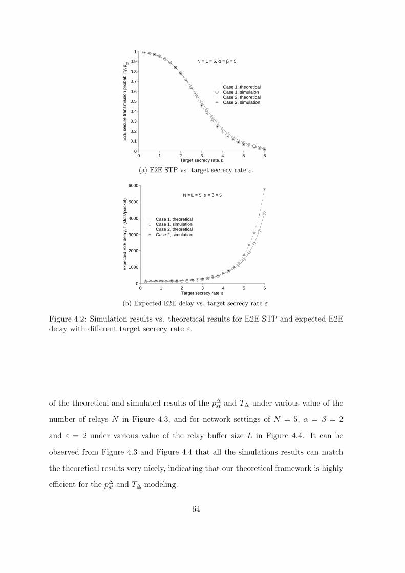
0 1 2 3 4 5 60
0.1
0.2
0.3
0.4
0.5
0.6
0.7
0.8
0.9
1
Target secrecy rate, ε
E2E
sec
ure
tran
smis
sion
pro
babi
lity,
pst
Case 1, theoreticalCase 1, simulaionCase 2, theoreticalCase 2, simulation
N = L = 5, α = β = 5
(a) E2E STP vs. target secrecy rate ε.
0 1 2 3 4 5 60
1000
2000
3000
4000
5000
6000
Target secrecy rate, ε
Exp
ecte
d E
2E d
elay
, T (
slot
s/pa
cket
)
Case 1, theoreticalCase 1, simulationCase 2, theoreticalCase 2, simulation
N = L = 5, α = β = 5
(b) Expected E2E delay vs. target secrecy rate ε.
Figure 4.2: Simulation results vs. theoretical results for E2E STP and expected E2Edelay with different target secrecy rate ε.
of the theoretical and simulated results of the p∆st and T∆ under various value of the
number of relays N in Figure 4.3, and for network settings of N = 5, α = β = 2
and ε = 2 under various value of the relay buffer size L in Figure 4.4. It can be
observed from Figure 4.3 and Figure 4.4 that all the simulations results can match
the theoretical results very nicely, indicating that our theoretical framework is highly
efficient for the p∆st and T∆ modeling.
64

0 5 10 15 200.6
0.65
0.7
0.75
0.8
0.85
0.9
0.95
1
Number of relays, N
E2E
sec
ure
tran
smis
sion
pro
babi
lity,
pst
Case 1, theoreticalCase 1, simulationCase 2, theoreticalCase 2, simulation
L = 5, α = β = 5, ε = 2
(a) E2E STP vs. number of relays N .
0 5 10 150
100
200
300
400
500
600
Number of relays, N
Exp
ecte
d E
2E d
elay
, T (
slot
s/pa
cket
)
Case 1, theoreticalCase 1, simulationCase 2, theoreticalCase 2, simulation
L = 5, α = β = 5, ε = 2
(b) Expected E2E delay vs. number of relays N .
Figure 4.3: Simulation results vs. theoretical results for E2E STP and expected E2Edelay with different number of relays N .
4.4.3 Performance Discussion
Based on our theoretical results, we now study the effects of the network param-
eters (e.g., ε, N and L) on the security and delay performances (p∆st and T∆) of the
concerned system. Regarding the effects of target secrecy rate ε, we can see from
Figure 4.2 that the p∆st decreases as the target secrecy rate ε increases and the T∆ in-
creases as ε increases in both case 1 and case 2. This is because that, the buffer-aided
relay selection scheme (See Section 4.2) allows a packet to be transmitted only if the
instantaneous secrecy capacity of the selected link is higher than ε. So, as ε increases,
65

0 5 10 150.73
0.74
0.75
0.76
0.77
0.78
0.79
Buffer size, L
E2E
sec
ure
tran
smis
sion
pro
babi
lity,
pst
Case 1, theoreticalCase 1, simulationCase 2, theoreticalCase 2, simulation
N = 5, α = β = 5, ε = 2
(a) E2E STP vs. buffer size L.
0 5 10 150
500
1000
1500
2000
2500
Buffer size, L
Exp
ecte
d E
2E d
elay
, T (
slot
s/pa
cket
)
Case 1, theoreticalCase 1, simulationCase 2, theoreticalCase 2, simulation
N = 5, α = β = 5, ε = 2
(b) Expected E2E delay vs. buffer size L.
Figure 4.4: Simulation results vs. theoretical results for E2E STP and expected E2Edelay with different buffer size L.
the probability of securely transmitting a packet will decrease for each transmission,
which will result in a lower p∆st. Moreover, as the packet has to be stored in the relay
buffer to wait for the next transmission if the current link is not secure, which will
cause a larger queuing delay of the packet and thus a higher T∆.
For the effects of the number of relays N on the p∆st and T∆, we can see from Fig
4.3a that the p∆st increases as N increases for both case 1 and case 2, and from 4.3b
that T∆ also increases as the number of relays N increases. This is because that more
relays will introduce more available links for the transmission and thus a higher p∆st.
On the other hand, however, more relays will result in a higher queuing delay and
66
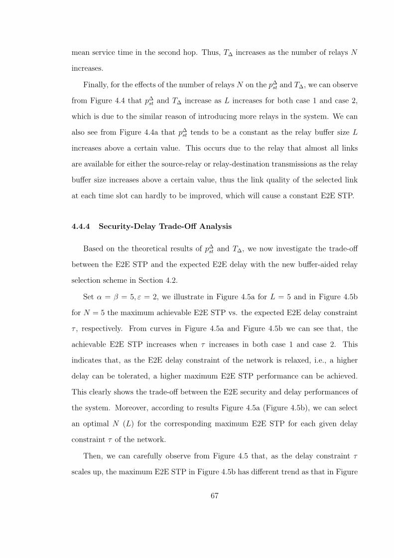
mean service time in the second hop. Thus, T∆ increases as the number of relays N
increases.
Finally, for the effects of the number of relays N on the p∆st and T∆, we can observe
from Figure 4.4 that p∆st and T∆ increase as L increases for both case 1 and case 2,
which is due to the similar reason of introducing more relays in the system. We can
also see from Figure 4.4a that p∆st tends to be a constant as the relay buffer size L
increases above a certain value. This occurs due to the relay that almost all links
are available for either the source-relay or relay-destination transmissions as the relay
buffer size increases above a certain value, thus the link quality of the selected link
at each time slot can hardly to be improved, which will cause a constant E2E STP.
4.4.4 Security-Delay Trade-Off Analysis
Based on the theoretical results of p∆st and T∆, we now investigate the trade-off
between the E2E STP and the expected E2E delay with the new buffer-aided relay
selection scheme in Section 4.2.
Set α = β = 5, ε = 2, we illustrate in Figure 4.5a for L = 5 and in Figure 4.5b
for N = 5 the maximum achievable E2E STP vs. the expected E2E delay constraint
τ , respectively. From curves in Figure 4.5a and Figure 4.5b we can see that, the
achievable E2E STP increases when τ increases in both case 1 and case 2. This
indicates that, as the E2E delay constraint of the network is relaxed, i.e., a higher
delay can be tolerated, a higher maximum E2E STP performance can be achieved.
This clearly shows the trade-off between the E2E security and delay performances of
the system. Moreover, according to results Figure 4.5a (Figure 4.5b), we can select
an optimal N (L) for the corresponding maximum E2E STP for each given delay
constraint τ of the network.
Then, we can carefully observe from Figure 4.5 that, as the delay constraint τ
scales up, the maximum E2E STP in Figure 4.5b has different trend as that in Figure
67
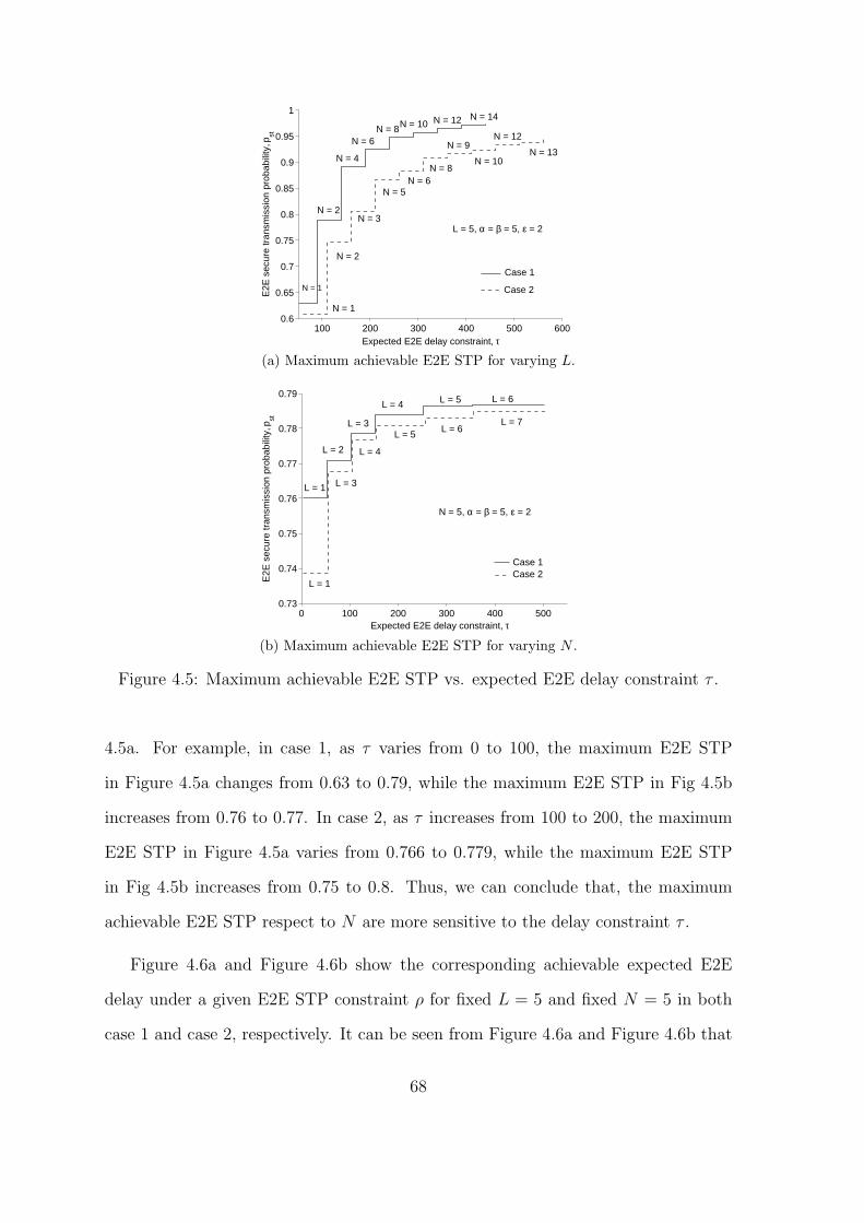
100 200 300 400 500 6000.6
0.65
0.7
0.75
0.8
0.85
0.9
0.95
1
Expected E2E delay constraint, τ
E2E
sec
ure
tran
smis
sion
pro
babi
lity,
pst
L = 5, α = β = 5, ε = 2
Case 1
Case 2
N = 1
N = 1
N = 2
N = 3
N = 5N = 6
N = 8
N = 9
N = 10
N = 12
N = 13
N = 2
N = 4
N = 6N = 8N = 10 N = 12 N = 14
(a) Maximum achievable E2E STP for varying L.
0 100 200 300 400 5000.73
0.74
0.75
0.76
0.77
0.78
0.79
Expected E2E delay constraint, τ
E2E
sec
ure
tran
smis
sion
pro
babi
lity,
pst
Case 1 Case 2
N = 5, α = β = 5, ε = 2
L = 1
L = 3
L = 4
L = 5L = 6
L = 7
L = 1
L = 2
L = 3
L = 4 L = 5 L = 6
(b) Maximum achievable E2E STP for varying N .
Figure 4.5: Maximum achievable E2E STP vs. expected E2E delay constraint τ .
4.5a. For example, in case 1, as τ varies from 0 to 100, the maximum E2E STP
in Figure 4.5a changes from 0.63 to 0.79, while the maximum E2E STP in Fig 4.5b
increases from 0.76 to 0.77. In case 2, as τ increases from 100 to 200, the maximum
E2E STP in Figure 4.5a varies from 0.766 to 0.779, while the maximum E2E STP
in Fig 4.5b increases from 0.75 to 0.8. Thus, we can conclude that, the maximum
achievable E2E STP respect to N are more sensitive to the delay constraint τ .
Figure 4.6a and Figure 4.6b show the corresponding achievable expected E2E
delay under a given E2E STP constraint ρ for fixed L = 5 and fixed N = 5 in both
case 1 and case 2, respectively. It can be seen from Figure 4.6a and Figure 4.6b that
68
0.6 0.65 0.7 0.75 0.8 0.85 0.9 0.95 10
100
200
300
400
500
600
E2E secure transmission probability constraint, ρ
Exp
ecte
d E
2E d
elay
, T (
slot
s/pa
cket
) L = 5, α = β = 5, ε = 2
Case 1
Case 2
N = 1
N = 1
N = 2N = 3
N = 5
N = 11
N = 15
N = 15
N = 11
N = 7N = 4
N = 3N = 2
(a) Minimum achievable expected E2E delay forvarying N .
0.72 0.73 0.74 0.75 0.76 0.77 0.78 0.790
10
20
30
40
50
60
70
80
90
E2E secure transmission probability constraint, ρ
Exp
ecte
d E
2E d
elay
, T (
slot
s/pa
cket
) N =5, α = β = 5, ε = 2
L = 1 L = 1
L = 2
L = 3
L = 4
L = 3Case 1
Case 2
(b) Minimum achievable expected E2E delay forvarying L.
Figure 4.6: Minimum achievable expected E2E delay vs. E2E STP constraint ρ.
the minimum achievable expected E2E delay increases as the E2E STP constraint ρ
increases. Notice that a higher ρ means a higher security requirement of the system.
Thus, the results in Figure 4.6a and Figure 4.6b indicate that, to improve the security
performance of the system, extra delay will be introduced in the system, which also
shows the trade-off between the E2E security and delay performances of the concerned
system.
We can also see from Figure 4.6a and Figure 4.6b that, as the E2E STP constraint
ρ increases above a certain value, the minimum expected E2E delay becomes indeter-
69

minable. This is because that, for given α, β and the target secrecy rate ε, the E2E
STP will finally converges to the corresponding threshold as N (resp. L ) increase
(See results in Figure 4.6a and Figure 4.6b). Thus, as ρ increases above a certain
value, we cannot determine the corresponding L and N and the minimum expected
E2E delay thus cannot be determined.
A further observation from Figure 4.6a and Figure 4.6b shows that, as ρ increases,
the trend of minimum expected E2E delay respect to N and L are different. For
example, as ρ increases from 0.72 to 0.8 in case 1, the minimum E2E delay increases
from 50 to 65 in Figure 4.6b while the minimum E2E delay increases from 3 to 56
in Figure 4.6a. In case 2, as ρ increases from 0.72 to 0.8, the minimum E2E delay
in Figure 4.6b increases from 70 to 100, but the minimum E2E delay in Figure 4.6a
increases from 3 to 90. Thus, compared with the minimum achievable expected E2E
delay respect to N , the minimum achievable expected E2E delay respect to L depends
more heavily on ρ.
4.4.5 Effects of Eavesdropper’s Decoding Strategy on E2E STP and E2E
Delay
Based on our theoretical results, we explore in this section the effects of eavesdrop-
per’s decoding strategy on the E2E STP and the expected E2E delay performances
of different buffer-aided relay selection schemes.
In Figure 4.7, we plot the E2E STP of the Max-Ratio buffer-aided relay selection
scheme and our proposed scheme for network settings of N = L = 5, α = β = 5 in
both case 1 (resp. Figure 4.7a) and case 2 (resp. Figure 4.7b) by varying the target
secrecy rate ε. We can see from the Figure 4.7 that E2E STP of our new proposed
buffer-aided relay selection scheme is always higher than that of the conventional
Max-Ratio buffer-aided relay section scheme, showing that our proposed new relay
selection scheme outperforms the Max-Ratio buffer-aided relay selection scheme in
70
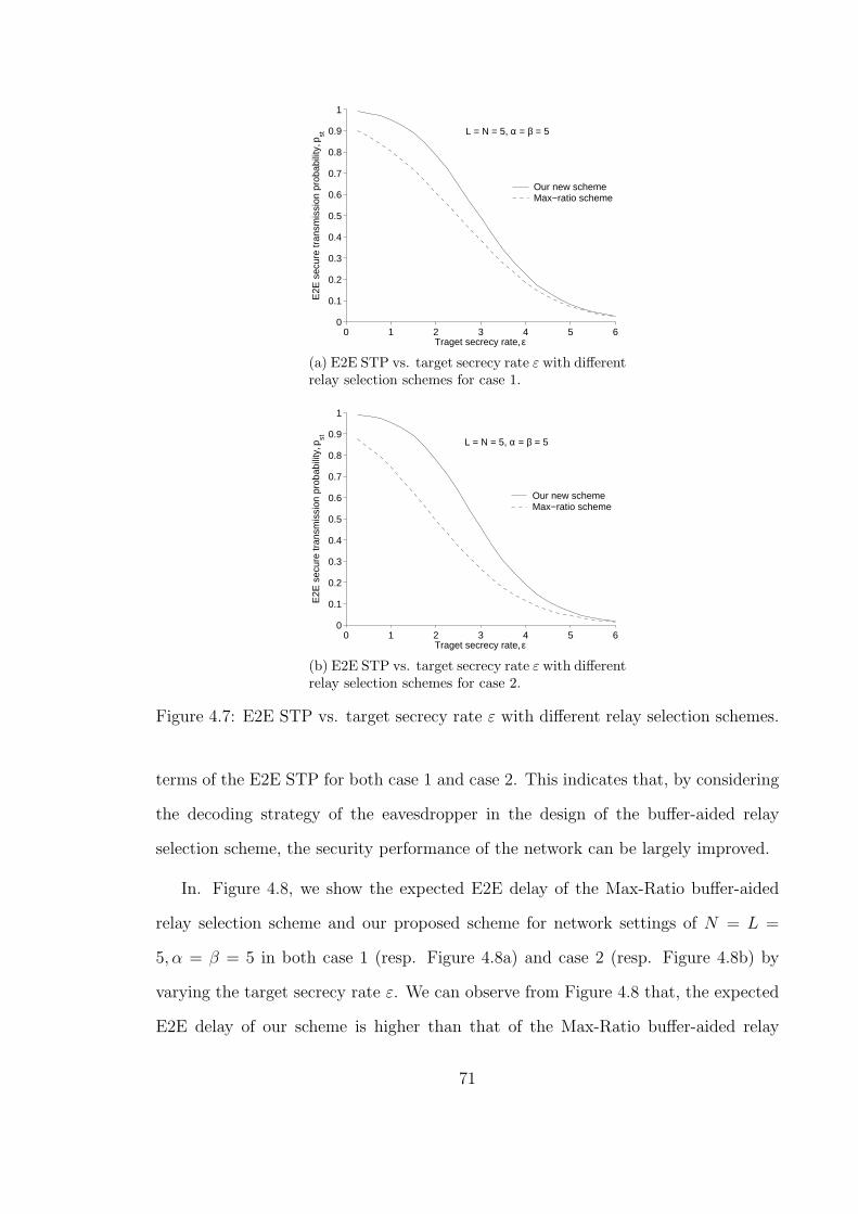
0 1 2 3 4 5 60
0.1
0.2
0.3
0.4
0.5
0.6
0.7
0.8
0.9
1
Traget secrecy rate, ε
E2E
sec
ure
tran
smis
sion
pro
babi
lity,
pst
Our new schemeMax−ratio scheme
L = N = 5, α = β = 5
(a) E2E STP vs. target secrecy rate ε with differentrelay selection schemes for case 1.
0 1 2 3 4 5 60
0.1
0.2
0.3
0.4
0.5
0.6
0.7
0.8
0.9
1
Traget secrecy rate, ε
E2E
sec
ure
tran
smis
sion
pro
babi
lity,
pst
Our new schemeMax−ratio scheme
L = N = 5, α = β = 5
(b) E2E STP vs. target secrecy rate ε with differentrelay selection schemes for case 2.
Figure 4.7: E2E STP vs. target secrecy rate ε with different relay selection schemes.
terms of the E2E STP for both case 1 and case 2. This indicates that, by considering
the decoding strategy of the eavesdropper in the design of the buffer-aided relay
selection scheme, the security performance of the network can be largely improved.
In. Figure 4.8, we show the expected E2E delay of the Max-Ratio buffer-aided
relay selection scheme and our proposed scheme for network settings of N = L =
5, α = β = 5 in both case 1 (resp. Figure 4.8a) and case 2 (resp. Figure 4.8b) by
varying the target secrecy rate ε. We can observe from Figure 4.8 that, the expected
E2E delay of our scheme is higher than that of the Max-Ratio buffer-aided relay
71

0 1 2 3 4 5 60
500
1000
1500
2000
2500
3000
3500
4000
4500
Traget secrecy rate, ε
Exp
ecte
d E
2E d
elay
, T (
slot
s/pa
cket
)
Our new schemeMax−ratio scheme
N = L = 5, α = β = 5
(a) Expected E2E delay vs. target secrecy rate εwith different relay selection schemes for case 1.
0 1 2 3 4 5 60
1000
2000
3000
4000
5000
6000
Traget secrecy rate, ε
Exp
ecte
d E
2E d
elay
, T (
slot
s/pa
cket
)
Our new schemeMax−ratio scheme
N = L = 5, α = β = 5
(b) Expected E2E delay vs. target secrecy rate εwith different relay selection schemes for case 2.
Figure 4.8: Expected E2E delay vs. target secrecy rate ε with different relay selectionschemes.
selection scheme. This is because, in our buffer-aided relay selection scheme, the
packet has to wait longer in the relay buffer for a strong link, which will result in a
larger queuing delay of the packet and thus a higher expected E2E delay.
4.5 Summary
This chapter investigates the buffer-aided relay selection scheme design for two-
hop wireless networks with DF relays. Unlike the available buffer-aided relay selection
72
schemes, the proposed buffer-aided relay selection scheme can defence the combining
decoding by the eavesdropper. The E2E STP and expected E2E delay are derived
in a closed for to validate the efficiency of the proposed scheme. The security-delay
trade-off issue is addressed to explore the maximum achievable E2E STP (minimum
achievable expected E2E delay) under a given expected E2E delay constraint (E2E
STP constraint). Moreover, the effects of the eavesdropper’s decoding strategy on the
security and delay performances are examined. Results show that our proposed buffer-
aided relay selection scheme outperforms the Max-Ratio buffer-aided relay selection
scheme in terms of the E2E STP. Since the packet in this work has to wait for a
longer time in the relay buffer, which will result in a larger E2E delay. Thus, we will
consider in our future work a delay-reduced buffer-aided relay selection scheme design
for secure two-hop wireless networks.
73


CHAPTER V
Conclusions
This final chapter summarize our contributions and points out several topics for
future research.
5.0.1 Summary of the Thesis
In this thesis, we studied the PHY security performances of two-hop wireless
networks, where the PHY security technique of buffer-aided relay selection is adopted
to ensure security of the communication. We first explored the E2E PHY security
performance of buffer-aided relay selection scheme for two-hop wireless networks with
RF relays, and then investigated the E2E PHY security performance of buffer-aided
relay selection scheme for two-hop wireless networks with DF relays.
For the PHY security performance of buffer-aided relay selection scheme for two-
hop wireless networks with RF relays, we studied in Chapter III the E2E STP and
expected E2E delay of a two-hop wireless network with one source-destination pair,
multiple relays each having a finite buffer and an eavesdropper who can only inde-
pendently decode its received packets. A general framework is first developed to
characterize the E2E delivery process of a tagged packet for the Max-Ratio buffer-
aided relay selection scheme. Based on the theoretical framework, we then determined
the E2E STP and the expected E2E delay of the scheme. The main results in Chapter
75
III showed that there is a clear trade-off between the E2E security performance and
delay performance in the concerned system. For example, if we impose a larger upper
bound (i.e., a less strict constraint) on the expected E2E delay, the maximum E2E
STP (in terms of either relay buffer size or number of relays) tends to increase, and
such trend is more sensitive to the variation of the number of relays than that of the
relay buffer size. On the other hand, if we impose a smaller lower bound (i.e., a more
strict constraint) on the E2E STP, the minimum expected E2E delay (in terms of
either relay buffer size or number of relays) tends to decrease, and this trend is more
sensitive to the variation of the relay buffer size than that of the number of relays.
This work is very important and can be future explored as guidelines for the design
of future networks.
For the PHY security performance of buffer-aided relay selection scheme with two-
hop wireless networks with DF relays, we investigated in Chapter IV the E2E STP
and expected E2E delay of a two-hop wireless network with one source-destination
pair, multiple relays and an eavesdropper who can combine the signals received in
two hops to conduct its decoding. We consider two eavesdropper CSI cases, i.e., the
case 1 where the instantaneous CSI of the eavesdropper channels are available, and
the case 2 where only distributions of the eavesdropper channels are available. Two
buffer-aided relay selection schemes were proposed to resist the combining decoding of
the packets by the eavesdropper such that the security performance of the concerned
network can be improved. Expressions of the E2E STP and expected E2E delay were
derived in a closed form to validate the efficiency of the proposed buffer-aided relay s-
election schemes. The security-delay trade-off was explored and the comparisons were
made between our proposed buffer-aided relay selection scheme and the conventional
Max-Ratio buffer-aided relay selection scheme to explore the effects of eavesdropper’s
decoding strategy on the network performances. The results in Section IV indicated
that our new scheme outperforms the Max-Ratio buffer-aided relay selection scheme
76

in terms of the E2E STP. With this work, we can provide theoretical models for the
two-hop wireless networks with DF relays, which can be applied for the performance
study of general multi-hop networks.
5.0.2 Future Works
The work presented in this thesis can be extended in many interesting directions.
• Packet delay-reduced buffer-aided relay selection scheme design for
two-hop wireless networks. In this thesis, we mainly focus on buffer-aided
relay selection schemes to enhance the security of wireless networks which is also
the main goals of available work. However, the packet in the relay buffer may
have to wait for a very long time for a good link. Since then the introduction of
buffers at the relays will naturally make a large packet delay for the concerned
network, especially for delay-sensitive networks. So a meaningful and interesting
work is to study the packet delay-reduced buffer-aided relay selection scheme
for secure wireless networks to explore or impose constraint on the maximum
delay that can be tolerated. For example, if the delay is near the maximum
allowable value, the relay may be forced to transmit the packet regardless of
the link quality. Another idea is that we can design the relay selection scheme
based on the states of the relay buffers, and give priority to relays whose buffer
is nearly full or empty.
• Secrecy capacity analysis for buffer-aided relay wireless networks. Due
to the buffer-aided relay selection schemes adopted in this thesis, the secrecy
capacity formulation of an individual link is enough for us to derive the main
results in this thesis, i.e., the E2E secure transmission probability and the ex-
pected E2E delay. This is because that, based on the buffer-aided relay selection
schemes adopted in this thesis, in each time slot we select a best relay for trans-
77
mission from all relays only based on the instantaneous secrecy capacity of each
link and states of all relay buffers. Thus, the above secrecy capacity formu-
lation of an individual link is enough for us to derive the main results in this
thesis. But the secrecy capacity formulation of the overall buffer-aided relay
networks is still an open problem. This is because that in such system, 1) each
packet now may go through three processes, i.e., the source-relay transmission
process, queuing process in a relay buffer and the relay-destination transmission
process; 2) in each time slot, there are three possible transmission states, i.e.,
source-relay transmission, relay-destination transmission and no transmission.
These two basic properties make the time T ′ it takes to transmit a packet from
the source to the destination highly uncertain (T ′ can vary from 2 to infinite),
and the possible number of transmission states during these T time slots is in
the order of O(3T′). These two main issues make the secrecy capacity formu-
lation and analysis of the buffer-aided relay system highly challenging (if not
impossible). Therefore, a new and dedicated study is deserved on the secrecy
capacity formulation of the general buffer-aided relay systems, and the study of
this topic is of great importance for the secrecy capacity of buffer-aided relay
wireless networks.
• f-cast buffer-aided relaying scheme in wireless networks. Available
buffer-aided relay selection schemes for secure two-hop wireless networks al-
ways select only one relay for the data transmission, making most of the relay
nodes non-transmitting during each transmission. This is a waste of the net-
work resource. Moreover, the data may have to wait for a long time to be
securely transmitted to the destination if the link from/to the message relay is
not secure, which will cause a larger delay of the data. While selecting multi-
ple message relays before each transmission can not only improve the security
performance of the network, but also can reduce the network delay. This is due
78

to two reasons: 1) Any secure transmission of the selected multiple message
relays means a secure and successful transmission of the network, i.e., a higher
secure transmission probability of the network; 2) The more message relays,
the higher probability to securely transmit the data, and thus a lower waiting
time of the data, which will lead to a lower delay performance of the network.
Therefore, the study of buffer-aided relay selection with multiple message re-
lays is an interesting and meaningful future direction for performances of secure
two-hop wireless networks. Actually, we can select the top n ”best” relay as the
message relays based on the link quality and the states of relay buffers to help
the transmission of a tagged packet.
79


APPENDICES
81

APPENDIX A
Proofs in Chapter III
A.1 Proof of Lemma 1
We first provide proof for the perfect eavesdropper CSI case. LetX =max
Rn:Ψsi (Qn )=L{|hSRn |2}
|hSE |2
and Y = maxRn:Ψsi (Qn )=0
{ |hRnD|2|hRnE |2 }. From [33], we know that the cumulative distribution
functions (CDFs) of X and Y are
FX(x) =
N1(si)∑n1=0
(N1(si)
n1
)(−1)n1
α
n1x+ α, (A.1)
and
FY (y) =
(y
β + y
)N2(si)
, (A.2)
respectively, where α = γsrγse
, β = γrdγre
. According to the relay selection scheme in
(3.4) and (3.5), transmission at each time slot occurs on the link with instantaneous
channel gain max{X,Y }. According to the transmission scheme in Section 3.2.2, the
probability of no state transition (i.e., sj = si) equals the probability of Rs < ε. Thus,
83
ai,i can be given by
ai,i = P (log(max{X, Y }) < ε) (A.3)
= P(max{X,Y } < 2ε) (A.4)
= FX(2ε) · FY (2
ε) (A.5)
= µPF(si), (A.6)
where µPF(si) is given in (3.9) with s = si and the last step follows after substituting
(A.1) and (A.2) into (A.3). Next, the probability that si moves to S−i can be given
by
P(S−i |si) = P (max{X, Y } ≥ 2ε, X < Y ) (A.7)
=
∫ 2ε
0
P(Y ≥ 2ε)fX(x)dx+
∫ ∞
2εP(Y > x)fX(x)dx (A.8)
= 1− µPF −∫ ∞
2εFY (x)fX(x)dx (A.9)
= 1− µPF(si)− νPF(si), (A.10)
where νPF(s) is given in (3.10) with s = si. Due to the i.i.d. property of channels, the
selection of one particular link within all available relay-destination links is equally
likely. Thus, for any state sn ∈ S−i , ai,j = 1−µPF(si)−νPF(si)
N2(si). Notice that the buffer
state can only move from si to si itself, the states in S−i or S+
i . Hence, for any state
sj ∈ S+i , ai,j =
νPF(si)N1(si)
.
Next, we provide proof for the partial eavesdropper CSI case. We first define new
random variables X′=
maxRn:Ψsi (Qn) =L
{|hSRn |2}
γseand Y
′=
maxRn:Ψsi (Qn) =0
{|hRnD|2}
γrewith CDF
given by FX′ (x) = (1−e−
xα )N1(si) and FY
′ (y) = (1−e−yβ )N2(si) , respectively. Following
the proof for the perfect eavesdropper CSI case, we can calculate the state transition
probabilities ai,j for sj = si, sj ∈ S−i and sj ∈ S+
i as µPT(si),1−µPT(si)−νPT(si)
N2(si)−1and
84

νPT(si)N1(si)
respectively, where
µPT(si) = FX′ (2ε) · FY
′ (2ε), (A.11)
is given by (3.11) after substituting FX′ (2ε) and FY ′ (2ε) in and
νPT(si) =
∫ ∞
2εFY
′ (x)fX′ (x)dx (A.12)
is given by (3.12) after calculating the above integral.
85


APPENDIX B
Proofs in Chapter IV
B.1 Proof of Lemma 5
We first provide proof for the case 1. Assuming that X = arg maxRn:Ψsi (Qn )=L
|hSRn |2|hSE |2 ,
Y = arg maxRn:Ψsi (Qn )=0
|hRnD|2|hSE |2+|hRnE |2 . From [33], we know that the cumulative distribu-
tion function (CDF) of X is
FX(x) =
N1(si)∑n1=0
(N1(si)
n1
)(−1)n1
α
n1x+ α, (B.1)
where α = γsrγse
. Then, let Y1 = |hRnD|2,Y2 = |hSE|2 + |hRnE|2, the CDF of Y1
Y2can be
determined as
87

FY1Y2
(y) = P(Y1 ≤ Y2y)
=
∫ ∞
0
Fy1(y2y)fY2(y2)dy2
=
∫ ∞
0
(1− e
− y2yγrd
)× 1
γse − γre
(e−
y1γse + e−
y1γre
)dy2
=1
γse − γre
∫ ∞
0
(1− e
− y1yγrd
)×(e−
y1γse + e−
y1γre
)dy2
= 1− γ2rd
(γrd + γsey)(γrd + γrey), (B.2)
where
FY1(y1) = 1− e− y1
γrd , (B.3)
and
FY2(y2) =1
γse − γre
(e−
y2γse + e−
y2γre
). (B.4)
Thus, based on the probability theory, the CDF of Y is
FY (y) =
[1− γ2
rd
(γrd + γsex)(γrd + γrex)
]N2
. (B.5)
According to the buffer-aided relay selection scheme in (4.3) and (4.4), a message
relay is selected at each time slot with instantaneous channel gain ratio max{X,Y },
and the state si remains unchanged as Cs < ε. Thus, the entry ai,i of the transition
88
matrix A can be given by
ai,i = P (log(max{X,Y }) < ε) (B.6)
= P(max{X, Y } < 2ε) (B.7)
= FX(2ε) · FY (2
ε) (B.8)
= µcase1(si), (B.9)
where µcase1(si) is given in (4.7) with s = si and the last step follows after substituting
(B.1) and (B.5) into (B.6). The probability that state si moves to state sj (sj ∈ S−)
can be given as
pi,j = P(X ≤ Y, Y ≥ 2ε)
=
∫ ∞
0
P(x ≤ Y, Y ≥ 2ε)fX(x)dx
=
∫ 2ε
0
P(Y ≥ 2ε)fX(x)dx+
∫ ∞
2εP(Y ≥ x)fX(x)dx
= P(Y ≥ 2ε)P(X ≤ 2ε) +
∫ ∞
2εfX(x)dx−
∫ ∞
2εFY (x)fX(x)dx
= 1− FX(2ε)FY (2
ε)−∫ ∞
2εFY (x)fX(x)dx
= 1− νcase1(si)− µcase1(si), (B.10)
where νcase1(s) is given in (4.8) with s = si. Since the selection of a particular relay
from all available relays is equally likely due to the i.i.d. property of main channels,
for any state sj ∈ S−i , ai,j =
1−µcase1(si)−νcase1(si)N2(si)
. Notice that a state si can only move
to three types of states, the si itself, the states in S−i and states in S+
i . Hence, for
any state sj ∈ S+i , ai,j =
νcase1(si)N1(si)
.
Next, we provide proof for case 2. Let X ′ = arg maxRn:Ψsi (Qn) =L
|hSRn |2γse
,
89

Y ′ = arg maxRn:Ψsi (Qn )=0
|hRnD|2γse+γre
with the CDFs of X ′ and Y ′ given by
FX′(x) = (1− e−xα )N1(si), (B.11)
and
FY ′(x) = (1− e− (γse+γre)x
γrd )N2(si), (B.12)
respectively. Following the proof for case 1, we can obtain ai,j for si = sj, sj ∈ S+i
and sj ∈ S−i as νcase2(si),
µcase2(si)N1(si)
and 1−µcase2(si)−νcase2(si)N2(si)−1
and respectively, where
µcase2(s) = FX′(2ε) · FY ′(2ε), (B.13)
is given in (4.9) by substituting FX′(2ε) and FY ′(2ε) into (B.13) and
νcase2(s) =
∫ ∞
2εFY
′ (x)fX′ (x)dx, (B.14)
is given in (4.10).
90

BIBLIOGRAPHY
91


BIBLIOGRAPHY
[1] D. Chen and H. Zhao, “Data security and privacy protection issues in cloud com-
puting,” IEEE International Conference on Computer Science and Electronics
Engineering (ICCSEE), vol. 1, pp. 647-651, 2012.
[2] T. Karygiannis and L. Owens, “Wireless network security,” NIST special publi-
cation, vol. 800, pp. 48, 2002.
[3] W. Stallings, Cryptography and network security: principles and practice, 5th ed.
Prentice Hall, January 2010.
[4] T. Chan Dai Truyen, J. Lee, and T. QS Quek, “Physical-layer secret key gener-
ation with colluding untrusted relays,” IEEE Trans. Wireless Commun., vol. 15,
no. 2, pp. 1517-1530, 2016.
[5] P. Shor, “Algorithms for quantum computation: discrete logarithms and factor-
ing,” in Foundations of Computer Science, 1994 Proceedings, 35th Annual Sym-
posium on, pp. 124-134, 1994.
[6] M. Bloch and J. Barros, “Physical-layer security: from information theory to
security engineering,” Cambridge University Press, 2011.
[7] A. Mukherjee, S. Fakoorian, J. Huang, and A. Swindlehurst, “Principles of phys-
ical layer security in multiuser wireless networks: A survey,” IEEE Commun.
Surveys Tuts, vol. 16, no. 3, pp. 1550?1573, 2014.
93

[8] M. Bloch, J. Barros, M. Rodrigues, and S. McLaughlin, “Wireless information-
theoretic security,” IEEE Trans. Inf. Theory, vol. 54, no. 6, pp. 2515-2534, Jun.
2008.
[9] Z. Zheng, Z. Haas, and M. Kieburg, “Secrecy Rate of distributed cooperative
MIMO in the presence of multi-antenna eavesdropper,” arXiv preprint arX-
iv:1709.05383, 2017.
[10] K. Cumanan, Z. Ding, B. Sharif, et al., “Secrecy rate optimizations for a MIMO
secrecy channel with a multiple-antenna eavesdropper,” IEEE Trans. Vehicular
Technology, vol. 63, no. 4, pp. 1678-1690, 2014.
[11] C. Wang and H. M. Wang, “On the secrecy throughput maximization for MISO
cognitive radio network in slow fading channels,” IEEE Trans. Inf. Forensics and
Security, vol. 9, no. 11, pp. 1814-1827, 2014.
[12] Y. Liang, H. V. Poor, and L. Ying, “Secrecy throughput of MANETs with mali-
cious nodes,” IEEE International Symposium Inf. Theory (ISIT 2009), pp. 1189-
1193, 2009.
[13] S. Gerbracht, C. Scheunert, and E. A. Jorswieck, “Secrecy outage in MISO sys-
tems with partial channel information,” IEEE Trans. Inf. Forensics and Security,
vol. 7, no. 2, pp. 704-716, 2012.
[14] B. V. Nguyen and K. Kim, “Secrecy outage probability of optimal relay selection
for secure AnF cooperative networks,” IEEE Commun. Letters, vol. 19, no. 12,
pp. 2086-2089, 2015.
[15] N. Yang, L. Wang, G. Geraci, et al., “Safeguarding 5G wireless communication
networks using physical layer security,” IEEE Commun. Magazine, vol. 53, no. 4,
pp. 20-27, 2015.
94

[16] A. D. Wyner, “The wire-tap channel,” The bell system technical journal, vol.
54, no. 8, pp. 1355-1387, 1975.
[17] I. Csiszarr and J. Korner, “Broadcast channels with confidential messages,” IEEE
Trans. Inf. Theory, vol. 24, no. 3, pp. 339-348, 1978.
[18] I. Krikidis, J. S. Thompson, and S. McLaughlin, “Relay selection for secure
cooperative networks with jamming,” IEEE Trans. Wireless Commun., vol. 10,
no. 8, pp. 5003-5011, Oct. 2009.
[19] J. Huang and A. Lee Swindlehurst, “Cooperative jamming for secure communi-
cations in MIMO relay networks,” IEEE Trans. Signal Process., vol. 59, no. 10,
pp. 4871-4884, 2011.
[20] R. A. Chou and A. Yener, “Polar coding for the multiple access wiretap channel
via rate-splitting and cooperative jamming,” IEEE International Symposium Inf.
Theory (ISIT), 2016.
[21] F. Zhu, F. Gao, and M. Yao, “Zero-forcing beamforming for physical layer securi-
ty of energy harvesting wireless communications,” EURASIP Journal on Wireless
Commun. and Networking, pp. 1-9, Mar. 2015.
[22] T. M. Hoang, T. Q. Duong, H. A. Suraweera, et al., “Cooperative beamforming
and user selection for improving the security of relay-aided systems,” IEEE Trans.
Wireless Commun., vol 63, no. 12, pp. 5039-5051, Dec. 2015.
[23] N. D. Sidiropoulos, T. N. Davidson, and Z. Q. Luo, “Transmit beamforming
for physical-layer multicasting,” IEEE Trans. Signal Process., vol. 54, no. 6, pp.
2239-2251, 2006.
[24] H. Wen, P. H. Ho, and B. Wu, “Achieving secure communications over wiretap
95
channels via security codes from resilient functions,” IEEE Wireless Commun.
Letters , vol. 3, no. 3, pp. 273-276, 2014.
[25] D. Klinc, J. Ha, S. W. Mclaughlin, et al., “LDPC codes for the Gaussian wiretap
channel,” Inf. Theory Workshop, pp. 95-99, 2009.
[26] W. K. Harrison, J. Almeida, M. R. Bloch, et al., “Coding for secrecy: An
overview of error-control coding techniques for physical-layer security,” IEEE Sig-
nal Process. Magazine, vol. 30, no. 5, pp. 41-50, 2013.
[27] H. Fang, L. Xu, and K. K. R. Choo, “Stackelberg game based relay selection
for physical layer security and energy efficiency enhancement in cognitive radio
networks,” Applied Mathematics and Computation, vol. 296, pp. 153-167, 2017.
[28] N. Nomikos, A. Nieto, P. Makris, D. N. Skoutas, et al., “Relay selection for
secure 5G green communications,” Telecommunication Systems, vol. 59, no. 1,
pp. 169-187, 2015.
[29] H. Hu, R. Lu, C. Huang, and Z. Zhang, “PTRS: a privacy-preserving trust-based
relay selection scheme in VANETs,” Peer-to-Peer Networking and Applications,
pp. 1-15, 2016.
[30] J. Huang and A. Lee Swindlehurst, “Buffer-aided relaying for two-hop secure
communication,” IEEE Trans. Wireless Commun., vol. 14, no. 1, Jan. 2015.
[31] A. El Shafie, A. Sultan, and N. Al-Dhahir, “Physical-layer security of a buffer-
aided full-duplex relaying System,” IEEE Commun. Letters, vol. 20, no. 9, pp.
1856-1859, 2016.
[32] A. El Shafie, D. Niyato, and N. Al-Dhahir, “Enhancing the PHY-layer security
of MIMO buffer-aided relay networks,” IEEE Wireless Commun. Letters, vol. 5,
no. 4, pp. 400-403, 2016.
96

[33] G. Chen, Z. Tian, Y. Gong, Z. Chen, and J. A. Chambers, “Max-ratio relay
selection in secure buffer-aided cooperative wireless networks,” IEEE Trans. Inf.
Forensics Security, vol. 9, no. 4, pp. 719-729, Apr. 2014.
[34] Y. Zhang, T. Liang, and A. Sun, “A new Max-ratio relay selection scheme in
secure buffer-aided cooperative wireless networks,” the 8th International Sympo-
sium on Computational Intelligence and Design (ISCID), vol. 1, 2015.
[35] X. Tang, Y. Cai, Y. Huang, T. Q. Duong, W. Yang, and W. Yang, “Se-
crecy outage analysis of buffer-aided cooperative MIMO relaying systems,”
IEEE Tran. Vehicular Technology, 2017, [Online]. Available: Early Access. doi:
10.1109/TVT.2017.2695500.
[36] X. Tang, Y. Cai, Y. Huang, T. Q. Duong, W. Yang, and W. Yang, “Secrecy out-
age analysis of buffer-aided multi-antenna relay systems without eavesdropper’s
CSI,” 2017 IEEE International Conference on Communications (ICC), pp. 1-6,
2017.
[37] X. Luo and Rodrigo C. de Lamare, “Study of relay selection for physical-layer
security in buffer-aided relay networks based on the secrecy rate criterion,” arXiv
preprint arXiv:1605.04487, 2016.
[38] X. Liao, Z. Wu, Y. Zhang, and X. Jiang, “The delay-security trade-off in two-hop
buffer-aided relay wireless network,” International Conference on Networking and
Network Applications, pp. 173-177, 2016.
[39] X. Liao, Y. Zhang, Z. Wu, et al., “On security-delay trade-off in two-hop wireless
networks with buffer-aided relay selection,” IEEE Trans. Wireless Commun., vol.
17, no. 3, pp. 1893-1906, 2018.
[40] J. He, J. Liu, Y. Shen, et al., “Link selection for secure cooperative networks
with buffer-aided relaying,” arXiv preprint arXiv:1802.06538, 2018.
97

[41] S. Luo and K. C. Teh, “Buffer state based relay selection for buffer-aided coop-
erative relaying systems,” IEEE Trans. Wireless Commun., vol. 14, no. 10, pp.
5430-5439, 2015.
[42] T. Islam, A. Ikhlef, R. Schober, et al., “Diversity and delay analysis of buffer-
aided BICM-OFDM relaying,” IEEE Trans. Wireless Commun., vol. 12, no. 11,
pp. 5506-5519, 2013.
[43] V. Jamali, N. Zlatanov, and R. Schober, “Bidirectional buffer-aided relay net-
works with fixed rate transmission-Part I: Delay-unconstrained case,” IEEE Trans.
Wireless Commun., vol. 14, no. 3, pp. 1323-1338, 2015.
[44] F. Wang, J. Huang, and Y. Zhao, “Delay sensitive communications over cognitive
radio networks,” IEEE Trans. Wireless Commun., vol. 11, no. 4, pp. 1402-1411,
2012.
[45] S. S. Ikki and M. H. Ahmed, “Performance analysis of adaptive decode-and-
forward cooperative diversity networks with best-relay selection,” IEEE Trans.
Commun., vol. 58, no. 1, 2010.
[46] R. Senanayake, S. Atapattu, J. Evans, et al., “Decentralized relay selection in
multi-user multihop decode-and-forward relay networks,” IEEE Trans. Wireless
Commun., 2018.
[47] J. Mo, M. Tao and Y. Liu, “Relay placement for physical layer security: A secure
connection perspective,” IEEE Commun. Letters, vol. 16, no. 6, pp. 878-881, 2012.
[48] O. O. Koyluoglu, C. E. Koksal, and H. El Gamal, “On secrecy capacity scaling in
wireless networks,” IEEE Trans. Inf. Theory, vol. 58, no. 5, pp. 3000-3015, 2012.
[49] P. K. Gopala, L. Lai, and H. El Gamal, “On the secrecy capacity of fading
channels,” IEEE Trans. Info. Theory, vol. 54, no. 10, pp. 4687-4698, 2008.
98
[50] X. Zhang, X. Zhou, and M. R. McKay, “On the design of artificial-noise-aided se-
cure multi-antenna transmission in slow fading channels,” IEEE Trans. Vehicular
Technology, vol. 62, no. 5, pp. 2170-2181, 2013.
[51] N. Yang, S. Yan, J. Yuan, et al., “Artificial noise: Transmission optimization in
multi-input single-output wiretap channels,” IEEE Trans. Commun., vol. 63, no.
5, pp. 1771-1783, 2015.
[52] C. Wang and H. M. Wang, “On the secrecy throughput maximization for MISO
cognitive radio network in slow fading channels,” IEEE Trans. Inf. Forensics and
Security, vol. 9, no. 11, pp. 1814-1827, 2014.
[53] C. Cai, Y. Cai, X. Zhou, et al., “When does relay transmission give a more secure
connection in wireless ad hoc networks,” IEEE Trans. Inf. Forensics and Security,
vol. 9, no. 4, pp. 624-632, 2014.
[54] I. Krikidis, T. Charalambous, and J. S. Thompson, “Buffer-aided relay selection
for cooperative diversity systems without delay constraints,” IEEE Trans. Wireless
Commun., vol. 11, no. 5, pp. 1957-1967, 2012.
[55] J. R. Norris, Markov Chains, Cambridge, U.K.: Cambridge Univ. Press, 1998.
[56] T. Robertazzi, “Computer Networks and Systems: Queueing Theory and Per-
formance Evaluation,” Springer, 2012.
[57] C++ simulator for E2E delay and STP performance in two-hop wireless net-
works, 2017, [Online]. Available: http://xnliao.blogspot.com/.
[58] N. C. Beaulieu and J. Hu, “A closed-form expression for the outage probabili-
ty of decode-and-forward relaying in dissimilar Rayleigh fading channels,” IEEE
Commun. Letters, vol. 10, no. 12.
99
[59] Z. Yi and I. M. Kim, “Diversity order analysis of the decode-and-forward co-
operative networks with relay selection,” IEEE Trans. Wireless Commun., vol. 7,
no. 5, 2008.
[60] J. He, V. Tervo, S. Qian, et al., “Performance analysis of lossy decode-and-
forward for non-orthogonal MARCs,” IEEE Trans. Wireless Commun., vol. 17,
no. 3, pp. 1545-1558, 2018.
[61] H. Chen, C. Zhai, Y. Li, et al., “Cooperative strategies for wireless-powered
communications: An overview,” IEEE Wireless Commun., 2018.
[62] K. S. Gomadam and S. A. Jafar, “Optimal relay functionality for SNR maximiza-
tion in memoryless relay networks,” IEEE Journal on Selected Areas in Commun.,
vol. 25, no. 2, 2007.
[63] A. Ikhlef, D. S. Michalopoulos, and R. Schober, “Max-max relay selection for
relays with buffers,” IEEE Trans. Wireless Commun., vol. 11, no. 3, pp. 1124-1135,
2012.
[64] R. Bassily, E. Ekrem, X. He, et al., “Cooperative security at the physical layer:
A summary of recent advances,” IEEE Signal Process. Magazine, vol. 30, no. 5,
pp. 16-28, 2013.
100

PUBLICATIONS
101

Publications
Jounal Articles
[1] Xuening Liao, Yuanyu Zhang, Zhenqiang Wu, Yulong Shen, Xiaohong Jiang andHiroshi Inamura, On Security-Delay Trade-Off in Two-Hop Wireless Networks withBuffer-Aaided Relay Selection, IEEE Transactions on Wireless Communications17(3): 1893-1906, 2018.
[2] Xuening Liao, Yuanyu Zhang, Zhenqiang Wu, Xiaohong Jiang and Horoshi Ina-mura, Buffer-Aided Relay Selection Scheme for Secure Two-Hop Wireless Networkswith Decode-and-Forward Relays, Ad Hoc Networks, 2018. (Submitted)
[3] Ahamed Salem, Xuening Liao, Yulong Shen and Xiaohong Jiang, Provoking theAdversary by Detecting Eavesdropping and Jamming Attacks: A Game TheoreticalFramework, Special Issue on Wireless Communications and Mobile Computing,2018. (Accepted)
[4] Huihui Wu, Yuanyu Zhang, Xuening Liao, Yulong Shen and Xiaohong Jiang,Covert Wireless Communication in Two-Way Relay Channel, Ad Hoc Networks,2018. (Submitted)
Conference Papers
[5] Xuning Liao, Zhenqiang Wu, Yuanyu Zhang and Xiaohong Jiang, The Delay-Security Trade-Off in Two-Hop Buffer-Aided Relay Wireless Network, 2016 In-ternational Conference on Networking and Network Applications (NaNA 2016),Hakodate, 2016, pp. 173-177.
[6] Huihui Wu, Xuening Liao, Yulong Shen and Xiaohong Jiang, Limits of CovertCommunication on Two-Hop AWGN Channels, 2017 International Conference onNetworking and Network Applications (NaNA 2017), Nepal, 2017, pp. 42-47.
[7] Ahamed Salem, Xuening Liao and Yulong Shen, Provoking the Adversary byDual Detection Techniques: A Game Theoretical Framework, 2017 International
103
Conference on Networking and Network Applications (NaNA 2017), Nepal, 2017,pp. 326-329.
[8] Sasaki Kenda, Xuening Liao and Xiaohong Jiang, Cooperative jamming in a Two-Hop Relay Wireless Network with Buffer-Aided Relays, The Fifth InternationalSymposium on Computing and Networking (CANDAR 2017), Aomori, 2017.
104