Physical Layer
40
Computer Networks Chapter 2 Physical Layer
-
Upload
rutwik-jadhav -
Category
Internet
-
view
66 -
download
2
Transcript of Physical Layer

Computer Networks
Chapter 2
Physical Layer

Chap. 2- Physical Prepared by Rutwik
2
Chapter Overview2.1 Theoretical Basis For Data Communication
What every sophomore EE knows !!! How much data can be put on a wire? What are the limits imposed by a medium?
2.2 Transmission Media
Wires and fibers.
2.3 Wireless TransmissionRadio, microwave, infrared, unguided by a medium.
2.4 The Telephone System
The system invented 100 years ago to carry voice.
2.5 Narrowband ISDN
Mechanisms that can carry voice and data.

Chap. 2- Physical Prepared by Rutwik
3
DATA COMMUNICATION
THEORY
Overview
This is Physics or Electrical Engineering stuff.
It’s how we understand what is actually happening on a wire.
2.1 Theoretical Basis For Data Communication
2.2 Transmission Media
2.3 Wireless Transmission
2.4 The Telephone System
2.5 Narrowband ISDN
Chap. 2- Physical Prepared by Rutwik
4
DATA COMMUNICATION
THEORY
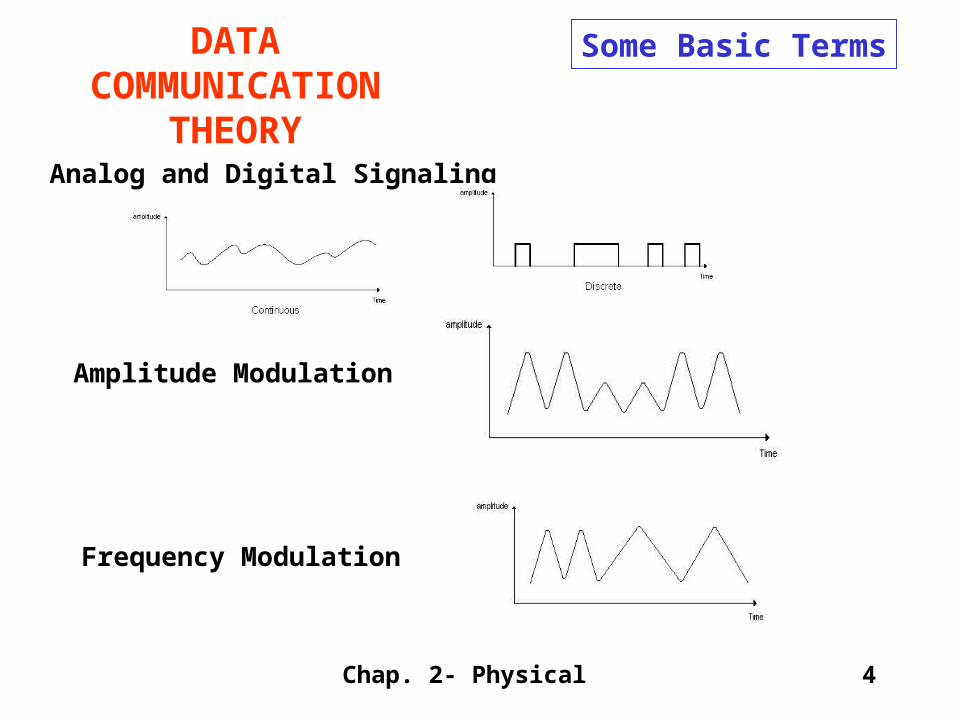
Some Basic Terms
Analog and Digital Signaling
Amplitude Modulation
Frequency Modulation

Chap. 2- Physical Prepared by Rutwik
5
DATA COMMUNICATION
THEORY
Some Basic Terms
Baseband and Broadband
Phase Modulation
Modems

Chap. 2- Physical Prepared by Rutwik
6
DATA COMMUNICATION
THEORY
Some Basic Terms
Synchronous – there’s a clock embedded in the wire that guarantees all users of that wire are based on that clock.
Asynchronous – there’s no clock. Users of the wire send signals when they feel like it.
Chap. 2- Physical Prepared by Rutwik
7
DATA COMMUNICATION
THEORY
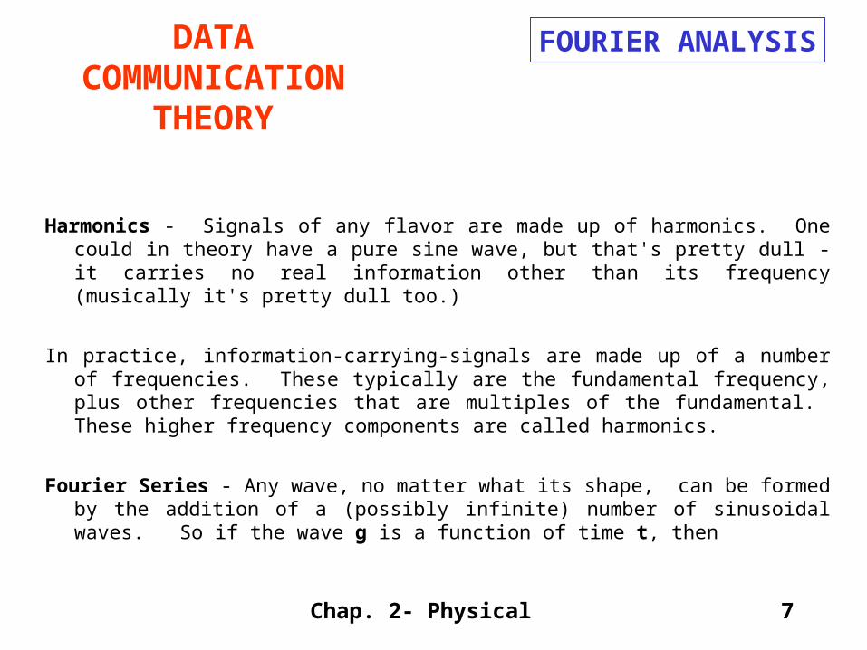
Harmonics - Signals of any flavor are made up of harmonics. One could in theory have a pure sine wave, but that's pretty dull - it carries no real information other than its frequency (musically it's pretty dull too.)
In practice, information-carrying-signals are made up of a number of frequencies. These typically are the fundamental frequency, plus other frequencies that are multiples of the fundamental. These higher frequency components are called harmonics.
Fourier Series - Any wave, no matter what its shape, can be formed by the addition of a (possibly infinite) number of sinusoidal waves. So if the wave g is a function of time t, then
FOURIER ANALYSIS

Chap. 2- Physical Prepared by Rutwik
8
DATA COMMUNICATION
THEORY
g(t) = c/2 + ninfAn sin( 2 n f t)
+ ninfBn cos( 2 n f t)The coefficients An and Bn are determined for each component - they represent
the amplitude of the individual waves.
The way to solve this equation is to take the function you're trying to analyze (say for a square wave):
g(t) = 1 ( 0 <= t < 1, 2 <= t < 3, .... )
= 0 ( 1 <= t < 2, 3 <= t < 4, .... )
then solve for
An = 2/T g(t)sin(2 n f t) dt
Bn = 2/T g(t)cos(2 n f t) dt
FOURIER ANALYSIS
Chap. 2- Physical Prepared by Rutwik
9
DATA COMMUNICATION THEORY
Let's look at this case for a couple of elements in the series.
FOURIER ANALYSIS

Chap. 2- Physical Prepared by Rutwik
10
DATA COMMUNICATION THEORY
Unfortunately, life isn't perfect. All frequencies aren't possible in a transmission medium. We'll do a quick detour in order to discuss capacitance here - this is what damps out higher frequencies. The Figure shows the affect of this distortion. Later on we'll see that some media are opaque to various frequencies - a second reason why signals can't get through.
Signals can also be intentionally distorted or constrained. Perhaps only a certain range of frequencies is allowed for each channel. This allows multiple channels per medium.
BANDWIDTH-LIMITED SIGNALS

Chap. 2- Physical Prepared by Rutwik
11
DATA COMMUNICATION THEORY
Wave Shape - A pure sine wave (the fundamental only) doesn't cut it. The receiver needs the signal to electrically stay high for some amount of time so it can distinguish the voltage - some degree of "squareness" is necessary requiring some harmonics in the signal.
Baud - The number of changes in the signal per second. A b baud line does not necessarily transmit b bits/second - each signal may convey several bits - for example if 8 voltages are possible per signal, then 3 bits are sent on every signal. If the signal is BINARY (only two voltage levels), then the bit rate is equal to the baud rate.
BANDWIDTH-LIMITED SIGNALS

Chap. 2- Physical Prepared by Rutwik
12
DATA COMMUNICATION THEORY
Voice-grade Line - is an ordinary telephone line. Its cutoff frequency is near 3,000 Hz.
If we assume:
1) 1 bit per baud,
2) that there are, in the best case, 8 harmonics,
BANDWIDTH-LIMITED SIGNALS
then
1) the bit rate is b bits/sec,
2) the frequency of the fundamental (also called the first harmonic) is b/8 Hz.
3) the highest harmonic passed through a voice grade line: 3000/(b/8) = 24,000/b.
4) The Table shows how this equation works in practice.
Chap. 2- Physical Prepared by Rutwik
13
DATA COMMUNICATION THEORY
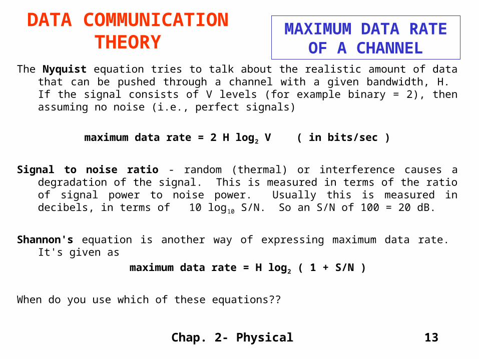
The Nyquist equation tries to talk about the realistic amount of data that can be pushed through a channel with a given bandwidth, H. If the signal consists of V levels (for example binary = 2), then assuming no noise (i.e., perfect signals)
maximum data rate = 2 H log2 V ( in bits/sec )
Signal to noise ratio - random (thermal) or interference causes a degradation of the signal. This is measured in terms of the ratio of signal power to noise power. Usually this is measured in decibels, in terms of 10 log10 S/N. So an S/N of 100 = 20 dB.
Shannon's equation is another way of expressing maximum data rate. It's given as
maximum data rate = H log2 ( 1 + S/N )
When do you use which of these equations??
MAXIMUM DATA RATE OF A CHANNEL

Chap. 2- Physical Prepared by Rutwik
14
Transmission Media
Overview
This section discusses the various types of wires/fibers/etc that can be used to carry data.
2.1 Theoretical Basis For Data Communication
2.2 Transmission Media
2.3 Wireless Transmission
2.4 The Telephone System
2.5 Narrowband ISDN

Chap. 2- Physical Prepared by Rutwik
15
Transmission Media
Hardware Stuff
MAGNETIC MEDIA: Sometimes it's cheaper and faster to load a box of tapes in your car !!!
TWISTED PAIR: Simply two wires twisted together - the twisting cuts down on electrical
interference. Heavily used in the phone system - the typical office has four pairs for
phones, etc. Category 3 and 5 - with 5 having more twists and better insulation.
BASEBAND COAXIAL CABLE: Used for digital transmissions (called baseband.) Good noise immunity. Data rates as high as 1 Gbps for short distances. Now being replaced by fiber.

Chap. 2- Physical Prepared by Rutwik
16
Transmission Media
Hardware Stuff
BROADBAND COAXIAL CABLE: Used for analog transmissions (called broadband.) Can run 300 MHz for long distances. Analog signaling has better S/N than digital signaling. Interfaces must convert digital signals to analog and vice versa. Designed for long distances - can use amplifiers.
FIBER OPTICS: Transmission of light through fiber - properties include total internal
reflection and attenuation of particular frequencies. Fiber Optic Networks - can be used for LANs and long-haul.

Chap. 2- Physical Prepared by Rutwik
17
Transmission Media
Hardware Stuff
Comparison of Fiber Optics and Copper Wire
Fiber Copper
Bandwidth Higher LowerDistance between repeaters 30 Km 5 KmInterference Low HighPhysical Smaller/LighterFlow Uni-directional Bi-directional

Chap. 2- Physical Prepared by Rutwik
18
Transmission Media
Connectors

Chap. 2- Physical Prepared by Rutwik
19
Transmission Media
Repeaters
Signal Regeneration
Clean up
Amplify
Distance Extension
Repeater functionality, plus...
Concentration Point
Signal Distribution Device
Management Functions
Hubs

Chap. 2- Physical Prepared by Rutwik
20
Wireless Transmission
Overview
So how do those signals magically get through the air to give us wireless computing.
2.1 Theoretical Basis For Data Communication
2.2 Transmission Media
2.3 Wireless Transmission
2.4 The Telephone System
2.5 Narrowband ISDN

Chap. 2- Physical Prepared by Rutwik
21
Wireless Transmission
Hardware Stuff
Though we will say little about this topic in the present course, it's clearly an extremely important topic. It's especially relevant since wireless transmission bypasses a great amount of infrastructure. It means that developing countries can leap ahead in technology without running miles of physical media.
Cell Phones:
Wireless Computing:

Chap. 2- Physical Prepared by Rutwik
22
The Telephone System
Overview
How is the phone system put together?
And how is voice and data transmitted on that system?
2.1 Theoretical Basis For Data Communication
2.2 Transmission Media
2.3 Wireless Transmission
2.4 The Telephone System
2.5 Narrowband ISDN
Chap. 2- Physical Prepared by Rutwik
23
The Telephone System
STRUCTURE OF THE PHONE SYSTEM
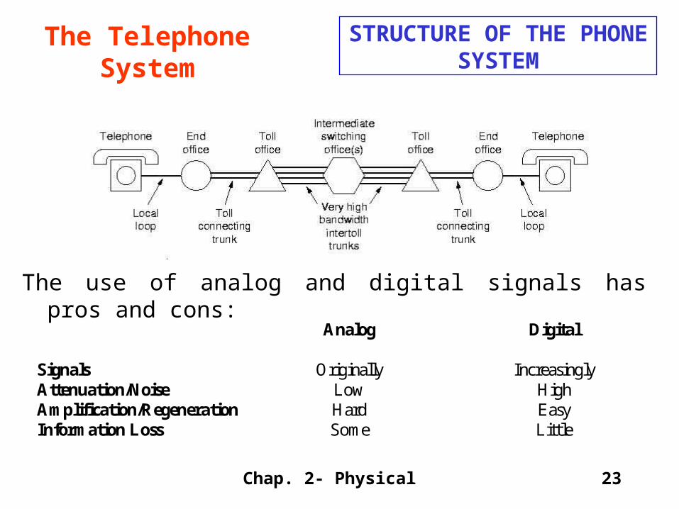
The use of analog and digital signals has pros and cons:
Analog Digital
Signals Originally IncreasinglyAttenuation/Noise Low HighAmplification/Regeneration Hard EasyInformation Loss Some Little

Chap. 2- Physical Prepared by Rutwik
24
The Telephone System
The Local Loop
This is the connection from the local switching station to your house. This is ultimately what controls the transmission speed to your house.
Transmission Impairments:
Attenuation - the loss of energy as the signal propagates.
Delay Distortion - different frequencies travel at different speeds so the wave form spreads out.
Noise - unwanted energy that combines with the signal - difficult to tell the signal from the noise.

Chap. 2- Physical Prepared by Rutwik
25
The Telephone System
Modems
A device that converts digital data to and from an analog signal for transmission over phone lines.
Because attenuation is frequency dependent, modems use a sine wave carrier of a particular frequency, and then modulate that frequency. Various modulations include:
Amplitude modulation: Two different amplitudes of sine wave are used to represent 1's and 0's.
Frequency modulation: Two (or more) different frequencies, close to the carrier frequency, are used.
Phase modulation: The phase of the sine wave is changed by some fixed amount.
Binary Signal

Chap. 2- Physical Prepared by Rutwik
26
The Telephone System
Modems
The 3 kHz phone line can only be sampled at 6 kHz. So it doesn't do any good to sample more - instead try to get in more bits per sample. For example, the Figure shows a combination of phase and amplitude modulation leading to multiple bits/baud.
Name points bits/sample bps
V.32 16 4 9600 V.32 bis 64 6 14,400 V.34 128 (including
parity) 7 28,800
Chap. 2- Physical Prepared by Rutwik
27
The Telephone System
Modems
In addition, modems use compression and error correction to increase the effective bits per second.
Full Duplex - Able to transmit in both directions on a wire at the same time.
Electrical Standards - take a look at the connector between an external modem and a computer. Those pins all have meanings and definitions.
Chap. 2- Physical Prepared by Rutwik
28
The Telephone System
TRUNKS AND MULTIPLEXING:
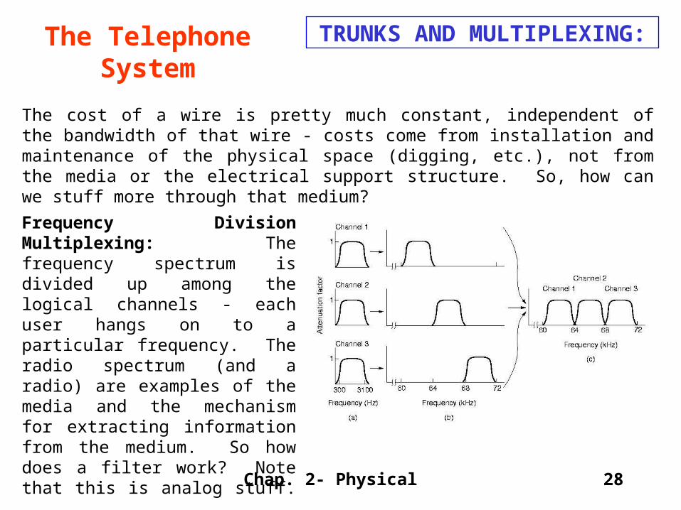
The cost of a wire is pretty much constant, independent of the bandwidth of that wire - costs come from installation and maintenance of the physical space (digging, etc.), not from the media or the electrical support structure. So, how can we stuff more through that medium?
Frequency Division Multiplexing: The frequency spectrum is divided up among the logical channels - each user hangs on to a particular frequency. The radio spectrum (and a radio) are examples of the media and the mechanism for extracting information from the medium. So how does a filter work? Note that this is analog stuff.

Chap. 2- Physical Prepared by Rutwik
29
The Telephone System
TRUNKS AND MULTIPLEXING:
Wavelength Division Multiplexing: The same as FDM, but applied to fibers. There's great potential for fibers since the bandwidth is so huge (25,000 GHz).
Time Division Multiplexing: In TDM, the users take turns, each one having exclusive use of the medium in a round robin fashion. TDM can be all digital.

Chap. 2- Physical Prepared by Rutwik
30
The Telephone System
TRUNKS AND MULTIPLEXING:
4 KHZ Analog/Voice 8,000 samples/sec ( sample every 125 usecond ).
T1 is the combination of 24 of these voice channels. See Figure on previous slide.
24 X 8 + 1 Framing Bit = 193 bits/125 usec --> 1.544 Mbps. When T1 is being used for digital data, the 24th channel is converted for use as synchronization.
T2 combines 4 X T1; T3 combines 6 X T2; T4 combines 7 X T3.
Differential Code Pulse Modulation: Assumes that a particular sample doesn't vary much from the previous one on that channel. Then we don't need 8 bits to represent the level (0 - 255), but simply 5 bits in order to indicate that the sample is (-16 - +15) as compared to the last sample.

Chap. 2- Physical Prepared by Rutwik
31
The Telephone System
SONET
(Synchronous Optical NETwork). Most long distance traffic in the US uses SONET. Design goals include:1. Common among different carriers - requires frequency, timing standards.2. Common among different countries - needed to supersede previous national standards.3. Multiplexed multiple digital channels together in a standard fashion.
Sonet is TDM - uses a highly accurate master clock. Data is transmitted SYNCHRONOUSLY.
A SONET frame of 810 bytes is transmitted every 125 usec. Because it's Synchronous, the frame is sent whether there's data to be carried or not. Data rate is 51.84 Mbps. This basic channel is called STS-1. Multiple channels can be multiplexed to get higher bandwidth.

Chap. 2- Physical Prepared by Rutwik
32
The Telephone System
SWITCHING
This is what happens inside the phone company - the various wires or fibers interconnect the switching centers. Methods of switching include:
Circuit Switching: A connection (electrical, optical, radio) is established from the caller phone to the callee phone. This happens BEFORE any data is sent.
Message Switching: The connection is determined only when there is actual data (a message) ready to be sent. The whole message is re-collected at each switch and then forwarded on to the next switch. This method is called store-and-forward. This method may tie up routers for long periods of time - not good for interactive traffic.
Packet Switching: Divides the message up into blocks (packets). Therefore packets use the transmission lines for only a short time period - allows for interactive traffic.

Chap. 2- Physical Prepared by Rutwik
33
The Telephone System
COMPARISON OF CIRCUIT SWITCHED AND PACKET SWITCHED NETWORKS
What are the relative characteristics of these two technologies?
Characteristic Circuit Switched Packet Switched Dedicated "copper" path Yes No Bandwidth Available Fixed Dynamic Potentially Wasted Bandwidth Yes No Store-and-Forward Transmission No Yes Each Packet Follows The SameRoute
Yes No
Call Setup Required Not Needed When can Congestion Occur At Setup Time On every Packet How are $$ Charged Per Minute Per Packet

Chap. 2- Physical Prepared by Rutwik
34
ISDNOverview
This is a method of combining Voice and Data over a single wire. Used heavily by the phone system in a number of applications.
2.1 Theoretical Basis For Data Communication
2.2 Transmission Media
2.3 Wireless Transmission
2.4 The Telephone System
2.5 Narrowband ISDN

Chap. 2- Physical Prepared by Rutwik
35
ISDNNARROWBAND - WHAT IS IT?
Integrated Services Digital Network: A completely digit, circuit-switched phone system. Integrates voice and non-voice services.
ISDN allows integration of computers and voice. It means that caller ID can be used to look up your account on the computer so that by the time a human answers the phone, a screen has your information already available.

Chap. 2- Physical Prepared by Rutwik
36
ISDNWHAT IS IT?
ISDN SYSTEM ARCHITECTURE: ISDN uses TDM to handle multiple channels. See Figure on previous page. For home use, the NT1 (Network Terminator) connects the twisted pair going to the phone company with the house wiring. Various ISDN devices can be connected to this NT1.
Businesses may have more channels active than the home configuration internal bus can handle. So a PBX ( Private Branch eXchange ) is used to provide the internal bus containing more switching capacity. This in turn is connected to NT1.

Chap. 2- Physical Prepared by Rutwik
37
ISDNWHAT IS IT?
THE ISDN INTERFACE:Typically a number of channels are combined together. In the USA, Primary Rate ISDN contains 23 channels (each 64 kbps carrying voice or data) + 1 channel for signaling and control (16 kbps digital channel.) In Europe, instead of 23 channels, 30 are used.
The primary Rate is designed to connect to a business with a PBX. As it turns out, most companies now need far more capacity than 64 kbps for the many uses beyond voice. So this is less than adequate.
N-ISDN may have a life as a connection to homes for people wanting to download images etc. But it's not useful for serious business applications.

Chap. 2- Physical Prepared by Rutwik
38
ISDNBROADBAND - WHAT IS IT?
This is a digital virtual circuit capable of 155 Mbps. Characteristics include:
ATM Packet Switched Technology.
The obsolescence of a vast amount of telephone technology which is based on circuit switching.

Chap. 2- Physical Prepared by Rutwik
39
ISDNComparing Virtual Circuits and
Circuit Switching
• Permanent virtual circuits that remain in place for long periods of time.
Switched virtual circuits that are set up and torn down with each request.
The method for establishing
these circuits is shown in the Figure. The circuit is really entries in a series of switches, each mapping a circuit number onto a forwarding line.
The service offered is connection oriented (from the customer's point of view) but is implemented with packet switching. Services offered include:

Chap. 2- Physical Prepared by Rutwik
40
SUMMARY2.1 Theoretical Basis For Data Communication
What every sophomore EE knows !!! How much data can be put on a wire? What are the limits imposed by a medium?
2.2 Transmission Media
Wires and fibers.
2.3 Wireless TransmissionRadio, microwave, infrared, unguided by a medium.
2.4 The Telephone System
The system invented 100 years ago to carry voice.
2.5 Narrowband ISDN
Mechanisms that can carry voice and data.