Preparation of poly(3-hydroxybutyrate-co-4-hydroxybutyrate ...
Upload
farzad-foroughiCategory
view
43download
3
Physical and mechanical properties of a poly-3-hydroxybutyrate-coated nanocrystalline hydroxyapatite scaffold for bone tissueengineering
Mohammad Reza Foroughi • Saeed Karbasi •
Reza Ebrahimi-Kahrizsangi
� Springer Science+Business Media, LLC 2011
Abstract A major challenge for tissue engineers is the
design of scaffolds with appropriate physical and
mechanical properties. The present research discusses the
formation of ceramic scaffolding in tissue engineering.
Hydroxyapatite (HAp) powder was made from bovine bone
by thermal treatment at 900 �C; 40, 50 and 60%wt porous
HAp was then produced using the polyurethane sponge
replication method. Scaffolds were coated with poly-3-
hydroxybutyrate (P3HB) for 30 s and 1 min in order to
increase the scaffold’s mechanical properties. XRD, SEM
and FT-IR were used to study phase structure, morphology
and agent groups, respectively. In XRD and FT-IR data,
established hydrogen bands between polymer and ceramic
matrix confirm that the scaffold is formed as a composite.
The scaffold obtained with 50%wt HAp and a 30 s coating
was 90% porous, with an average diameter of 100–400 lm,
and demonstrated a compressive strength and modulus of
1.46 and 21.27 MPa, respectively. Based on these results,
this scaffold is optimised for the aforementioned properties
and can be utilised in bone tissue engineering.
Keywords Hydroxyapatite (HAp) �Poly-3-hydroxybutyrate (P3HB) � Scaffold �Composite � Nanocrystal � Tissue engineering
1 Introduction
Tissue engineers study the design and production of new
tissues to regenerate damaged organs and replace lost
bones [1]. Bone repair and regeneration is a common and
complicated clinical problem in orthopedic surgery. In
huge fractures, the normal healing process fails to work
properly, and bone grafting surgery is therefore required
[2]. Recently, a great deal of interest has been directed
towards creating bioactive ceramic/polymer composites to
be used as bone grafting materials. In the past, scientists
cultured the necessary human cells ex vivo, but complex,
3-dimensional cell-network technology to replace damaged
tissue is ever expanding. A scaffold with an appropriate
physical framework is required in order to form tissue
based on such engineered methods. This scaffold must
allow cells to attach, migrate, duplicate, correspond inter-
cellularly and grow and replace tissues. Both polymer
matrix and ceramic matrix scaffolds have high porosity,
bioactivity, biodegradability and other physical properties
required for bone tissue engineering. Ceramic matrix
scaffolds have higher than polymer matrix scaffolds bio-
activity and are therefore recommended [3].
Natural bone is a 70%/30% inorganic/organic composite
material. Hydroxyapatite (HAp) is the main inorganic
component of bone and is a popular implant material in
bone surgery [4]. Due to its similar chemical composition,
mechanical resistance and stiffness to natural and tooth
bone cores and minerals, HAp has been widely used in
orthopedic and dental implants [5]. HAp minerals can
either be synthesised [6–12] or extracted from natural
sources [13–22].
Based on previous studies, high porosity, excellent
compressive strength and the possibility of cell migration
are important scaffold criteria [23–30]. Polymer replication
M. R. Foroughi � R. Ebrahimi-Kahrizsangi
Department of Materials Engineering, Najafabad Branch,
Islamic Azad University, Isfahan, Iran
S. Karbasi (&)
Medical Physics and Biomedical Engineering Group, School of
Medicine, Isfahan University of Medical Sciences, Isfahan, Iran
e-mail: [email protected]
123
J Porous Mater
DOI 10.1007/s10934-011-9518-1
methods allow for the formation of uniform scaffolds with
adjustable porosity [31–33]. The potential for improving
the mechanical properties of bioceramics/polymer com-
posite scaffolds by this approach has been demonstrated in
several systems, which have achieved mechanical proper-
ties, in particular compression strength, in the range of
values for cancellous bone [34]. Polymer coatings can be
used to reinforce these types of scaffolds. Miao et al.
coated poly lactic-co-glycolic acid (PLGA) onto ceramic
scaffolds of HAp tricalcium phosphate (TCP), giving the
coated ceramic scaffold a compressive strength and com-
pressive module of 0.66 and 16.85 MPa, respectively [35].
Tan et al. coated PLGA-Bioglass onto ceramic scaffolds of
HAp and reached compressive strength and compressive
module values of 1.36 and 24.58 MPa, respectively [36].
Jun et al. coated porous HAp scaffold with Apatite-Wol-
lastonite glass and 45S5 ceramic glass to increase com-
pressive strength [37]. TiO2 foam-like scaffolds with pore
size *300 lm and [95% porosity were fabricated by the
foam replication method by Novak et al. [38]. In order to
improve the structural integrity of the as-sintered foams,
which exhibited extremely low compression strength
(\0.045 MPa), PDLLA or PDLLA/Bioglass coatings were
developed. The PDLLA coating of a few microns in
thickness was shown to improve the mechanical properties
of the scaffold: the compressive strength was increased by
a factor of *7 (0.3 MPa). Moreover the composite coating
involving Bioglass particles was shown to impart the rutile
TiO2 scaffold with the necessary bioactivity for the inten-
ded applications in bone tissue engineering.
Many other components of biodegradable polymers and
bioactive ceramics have been utilised as biocompatible
scaffolds in tissue engineering. Polyhydroxyalkanoate
(PHA) is a biodegradable polymer used in tissue regener-
ation, drug delivery and patches, either alone or in
composite form [39]. One member of the PHA family is
poly-3-hydroxybutyrate (P3HB), which has a longer deg-
radation time than poly a-hydroxy acids (For example,
PLA and PLGA) and can be produced by various organ-
isms [40]. P3HB is biocompatibile with many different
types of cells. P3HB does not degrade into acidic
by-products, while degraded PLGA acidifies the immediate
environment around the cell [41]. P3HB also has piezo-
electric properties, which can play a critical role in stim-
ulating bone growth and regeneration [42]. Different
composite varieties have been made using P3HB matrix
and bioactive mineral particles like HAp, Wollastonite and
bioactive glasses, in order to improve the strength and
bioactivity level of composite [43]. However, due to a
lack of surface particles, bioactivity is only slightly
increased. Therefore, we recommend the use of P3HB to
reinforce ceramic matrix scaffolds to increase bioactivity
and strength, simultaneously. Bretcanu et al. [44] used
bacteria-derived P3HB to infiltrate 45S5 Bioglass scaffolds
intended for use in cancellous bone substitution after
trauma incidents. Pore morphology and macrostructure
before and after coating with P3HB, as well as coating
homogeneity, were investigated. Polymer coating consid-
erably increased the compressive strength of the scaffolds
(*1.5 MPa at 85% porosity).
To our knowledge, this is the first report on the forma-
tion of scaffolds from natural HAp coated with P3HB. HAp
nanocrystal powder was prepared from bovine bone by
thermal deposition, and porous scaffolds were constructed
using a polymer replication method. In order to enhance
mechanical properties, scaffolds were dip-coated P3HB.
Due to its high stability, mechanical amelioration and true
porosity, P3HB will be an important tool in bone tissue
engineering.
2 Materials and methods
2.1 Procurement of ceramic HAp powder
Bovine bones were boiled for 2 h to remove flesh and fat.
The bones were heated at 60 �C for 24 h to remove
moisture. To prevent blackening with soot during heating,
the bones are cut into small pieces (10 9 10 9 10 mm)
and heated at 400 �C for 3 h in air to allow for analysis of
their organic compositions. The resulting black bone ash
was heated for 2 h at 600, 700, 900 or 1,100 �C. The
resulting white nanocrystal HAp powder was used directly
to construct the ceramic scaffold.
2.2 Fabrication of ceramic slurry
The preparation of slurry stabilised with the proper addi-
tives is critical to scaffold formation; a variety of additives
with a range of biological properties have been studied
[45]. In this research, natural HAp powder with a grain size
of 70–80 nm has been utilised as the scaffold matrix. HAp
powder (40, 50 and 60%wt) was slowly dissolved in dou-
bly-distilled water to prevent agglomeration. The slurry
was stirred at 300 rpm for 30 min to give a homogenous
solution. To maximise mechanical strength, large amounts
of solid material should precipitate from the homogenised
solution onto the polyurethane sponge. We used ammo-
nium poly-methacrylate (DARVAN�C–N, R.T. Vanderbilt
Company, Norwalk, USA) to increase the weight per-
centage of solid substance above 1%wt. Carboxymethyl
cellulose (CMC, Hangzhou Hongbo Chemical Co. Ltd,
China) powder (1%wt) was gradually added to the solution
slowly in order to increase slurry flow. The solution was
stirred at 60 �C until it was fully homogeneous.
J Porous Mater
123
2.3 Preparation of porous HAp scaffold
A commercial polyurethane sponge (MEAY Co., Ltd.
China, average pore size 300–700 lm) was used in this
study. The sponge was immersed in ceramic slurry and
squeezed to remove air. Over time, the slurry was absorbed
into the sponge, and the shape was restored by elasticity.
When the sponge was completely filled it was removed
from the slurry and squeezed to remove excess slurry. The
resulting composite porous body was dried for 24 h in air.
Subsequently, the scaffolds were placed in a heat
treatment furnace. The HAp scaffold was formed in four
stages: (1) treatment at 600 �C, with a heating rate of 3 �C/
min for 1 h, to completely burn the sponge, (2) an increase
in temperature from 600 to 1,200 �C at a rate of 5 �C/min,
(3) treatment at 1,200 �C for 4 h to sinter the ceramic
scaffold and (4) cooling to room temperature at a cooling
rate of 5 �C/min. Cooled samples were removed from the
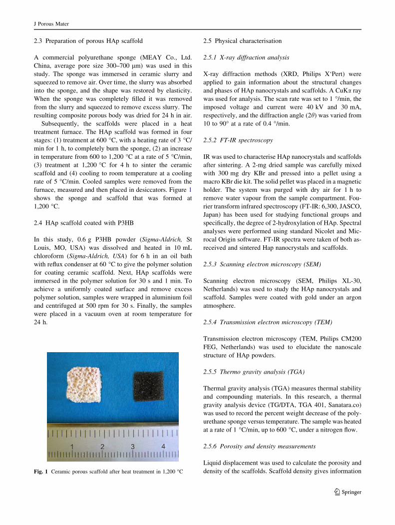
furnace, measured and then placed in desiccators. Figure 1
shows the sponge and scaffold that was formed at
1,200 �C.
2.4 HAp scaffold coated with P3HB
In this study, 0.6 g P3HB powder (Sigma-Aldrich, St
Louis, MO, USA) was dissolved and heated in 10 mL
chloroform (Sigma-Aldrich, USA) for 6 h in an oil bath
with reflux condenser at 60 �C to give the polymer solution
for coating ceramic scaffold. Next, HAp scaffolds were
immersed in the polymer solution for 30 s and 1 min. To
achieve a uniformly coated surface and remove excess
polymer solution, samples were wrapped in aluminium foil
and centrifuged at 500 rpm for 30 s. Finally, the samples
were placed in a vacuum oven at room temperature for
24 h.
2.5 Physical characterisation
2.5.1 X-ray diffraction analysis
X-ray diffraction methods (XRD, Philips X‘Pert) were
applied to gain information about the structural changes
and phases of HAp nanocrystals and scaffolds. A CuKa ray
was used for analysis. The scan rate was set to 1 �/min, the
imposed voltage and current were 40 kV and 30 mA,
respectively, and the diffraction angle (2h) was varied from
10 to 90� at a rate of 0.4 �/min.
2.5.2 FT-IR spectroscopy
IR was used to characterise HAp nanocrystals and scaffolds
after sintering. A 2-mg dried sample was carefully mixed
with 300 mg dry KBr and pressed into a pellet using a
macro KBr die kit. The solid pellet was placed in a magnetic
holder. The system was purged with dry air for 1 h to
remove water vapour from the sample compartment. Fou-
rier transform infrared spectroscopy (FT-IR: 6,300, JASCO,
Japan) has been used for studying functional groups and
specifically, the degree of 2-hydroxylation of HAp. Spectral
analyses were performed using standard Nicolet and Mic-
rocal Origin software. FT-IR spectra were taken of both as-
received and sintered Hap nanocrystals and scaffolds.
2.5.3 Scanning electron microscopy (SEM)
Scanning electron microscopy (SEM, Philips XL-30,
Netherlands) was used to study the HAp nanocrystals and
scaffold. Samples were coated with gold under an argon
atmosphere.
2.5.4 Transmission electron microscopy (TEM)
Transmission electron microscopy (TEM, Philips CM200
FEG, Netherlands) was used to elucidate the nanoscale
structure of HAp powders.
2.5.5 Thermo gravity analysis (TGA)
Thermal gravity analysis (TGA) measures thermal stability
and compounding materials. In this research, a thermal
gravity analysis device (TG/DTA, TGA 401, Sanatara.co)
was used to record the percent weight decrease of the poly-
urethane sponge versus temperature. The sample was heated
at a rate of 1 �C/min, up to 600 �C, under a nitrogen flow.
2.5.6 Porosity and density measurements
Liquid displacement was used to calculate the porosity and
density of the scaffolds. Scaffold density gives informationFig. 1 Ceramic porous scaffold after heat treatment in 1,200 �C
J Porous Mater
123
about the size, distribution and permeability of pores and
the presence of structural defects in sintered ceramic
frameworks [46]. Due to the hydrophobic properties of
polymer, 96% Ethanol, which can pass easily through
pores, was used instead of water. The mass of the ceramic
sample (W) was measured, and a volume (V1) of ethanol
was poured into a graduated cylinder and measured. The
sample was immersed in ethanol for 5 min until it became
saturated (V2). The discrepancy between volumes (V1-V2)
represents the volume of the scaffold. The ethanol-soaked
scaffold was removed from the graduated cylinder, and the
remaining volume was recorded as V3. V1-V3 represents
the volume of ethanol absorbed by the scaffold [45].
The following equation calculates density of the scaffold
(q), (Eq. 1):
q ¼ W
V2 � V3
ð1Þ
The following equation calculates the amount of open
porosity of the scaffold (e), (Eq. 2):
e ¼ V1 � V3
V2 � V3
ð2Þ
2.6 Mechanical characterisation
Machining and gripping the specimen is a major problem
in the mechanical characterisation of ceramic porous
scaffolds: conventional methods of mechanical character-
isation, such as tensile, biaxial and impact testing, are
usually inapplicable to porous materials [46]. Compression
impact tests for porous bone and HAp samples are instead
used [45–48]. Compressive strength and compressive
module tests for samples with and without P3HB coating
were performed using a compression impact tester (SAN-
TAM-Eng. Design co. LTD.) with a 10 KN load cell based
upon guidelines set in ASTM-D5024-95a. The dimensions
of each sample were 20 9 10 9 10 mm3 for the com-
pression impact test. As ceramic scaffolds are fragile, the
crosshead speed was set at 0.5 mm/min to prevent damage
to the ceramic structure. The load carried by the sample
was considered to be 30% of scaffold’s original length. The
elastic modulus was calculated as the slope of the initial
linear portion of the stress–strain curve. The yield strength
was determined from the cross point of the two tangents on
the stress–strain curve around the yield point.
3 Results and discussion
3.1 HAp nanocrystal
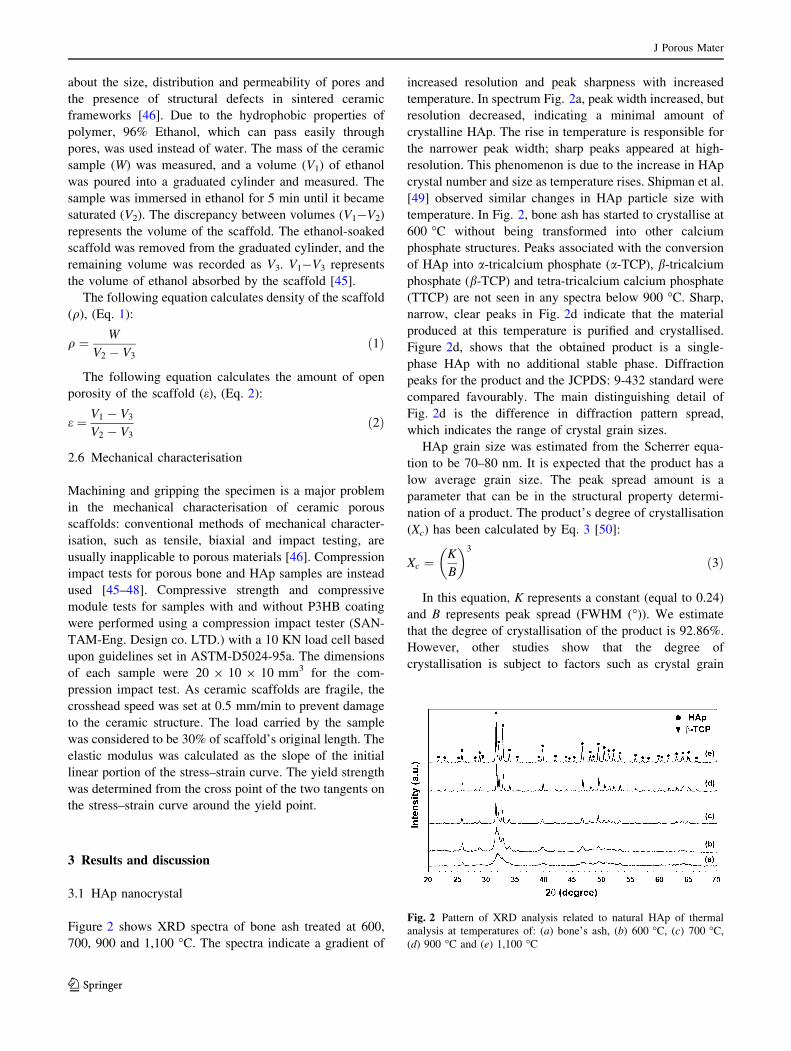
Figure 2 shows XRD spectra of bone ash treated at 600,
700, 900 and 1,100 �C. The spectra indicate a gradient of
increased resolution and peak sharpness with increased
temperature. In spectrum Fig. 2a, peak width increased, but
resolution decreased, indicating a minimal amount of
crystalline HAp. The rise in temperature is responsible for
the narrower peak width; sharp peaks appeared at high-
resolution. This phenomenon is due to the increase in HAp
crystal number and size as temperature rises. Shipman et al.
[49] observed similar changes in HAp particle size with
temperature. In Fig. 2, bone ash has started to crystallise at
600 �C without being transformed into other calcium
phosphate structures. Peaks associated with the conversion
of HAp into a-tricalcium phosphate (a-TCP), b-tricalcium
phosphate (b-TCP) and tetra-tricalcium calcium phosphate
(TTCP) are not seen in any spectra below 900 �C. Sharp,
narrow, clear peaks in Fig. 2d indicate that the material
produced at this temperature is purified and crystallised.
Figure 2d, shows that the obtained product is a single-
phase HAp with no additional stable phase. Diffraction
peaks for the product and the JCPDS: 9-432 standard were
compared favourably. The main distinguishing detail of
Fig. 2d is the difference in diffraction pattern spread,
which indicates the range of crystal grain sizes.
HAp grain size was estimated from the Scherrer equa-
tion to be 70–80 nm. It is expected that the product has a
low average grain size. The peak spread amount is a
parameter that can be in the structural property determi-
nation of a product. The product’s degree of crystallisation
(Xc) has been calculated by Eq. 3 [50]:
Xc ¼K
B
� �3
ð3Þ
In this equation, K represents a constant (equal to 0.24)
and B represents peak spread (FWHM (�)). We estimate
that the degree of crystallisation of the product is 92.86%.
However, other studies show that the degree of
crystallisation is subject to factors such as crystal grain
Fig. 2 Pattern of XRD analysis related to natural HAp of thermal
analysis at temperatures of: (a) bone’s ash, (b) 600 �C, (c) 700 �C,
(d) 900 �C and (e) 1,100 �C
J Porous Mater
123
size; the higher degree of crystallisation, the higher the
average size of crystal grains. In XRD spectra, the powder
obtained at 1,100 �C (Fig. 2e) shows a peak with poor
resolution at a 2h angle 29.475, related to the formation of
tricalcium phosphate beta (b-TCP) At lower temperatures,
no such peak appeared, indicating no transformation into
b-TCP during conversion of HAp unless heated above
1,100 �C. It is noteworthy that XRD analysis gave an
approximation amount related to the distribution of crystal
size. The variation in peak width illustrated a change in
crystal size distribution. In Fig. 3, the peak related to
b-TCP impurities emerged at 1,100 �C. Therefore, the best
temperature for scaffold construction was 900 �C.
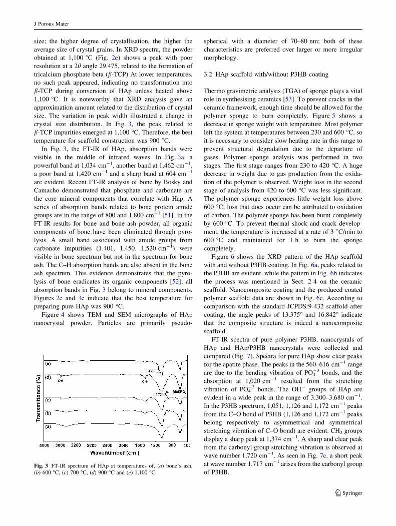
In Fig. 3, the FT-IR of HAp, absorption bands were
visible in the middle of infrared waves. In Fig. 3a, a
powerful band at 1,034 cm-1, another band at 1,462 cm-1,
a poor band at 1,420 cm-1 and a sharp band at 604 cm-1
are evident. Recent FT-IR analysis of bone by Bosky and
Camacho demonstrated that phosphate and carbonate are
the core mineral components that correlate with Hap. A
series of absorption bands related to bone protein amide
groups are in the range of 800 and 1,800 cm-1 [51]. In the
FT-IR results for bone and bone ash powder, all organic
components of bone have been eliminated through pyro-
lysis. A small band associated with amide groups from
carbonate impurities (1,401, 1,450, 1,520 cm-1) were
visible in bone spectrum but not in the spectrum for bone
ash. The C–H absorption bands are also absent in the bone
ash spectrum. This evidence demonstrates that the pyro-
lysis of bone eradicates its organic components [52]; all
absorption bands in Fig. 3 belong to mineral components.
Figures 2e and 3e indicate that the best temperature for
preparing pure HAp was 900 �C.
Figure 4 shows TEM and SEM micrographs of HAp
nanocrystal powder. Particles are primarily pseudo-
spherical with a diameter of 70–80 nm; both of these
characteristics are preferred over larger or more irregular
morphology.
3.2 HAp scaffold with/without P3HB coating
Thermo gravimetric analysis (TGA) of sponge plays a vital
role in synthesising ceramics [53]. To prevent cracks in the
ceramic framework, enough time should be allowed for the
polymer sponge to burn completely. Figure 5 shows a
decrease in sponge weight with temperature. Most polymer
left the system at temperatures between 230 and 600 �C, so
it is necessary to consider slow heating rate in this range to
prevent structural degradation due to the departure of
gases. Polymer sponge analysis was performed in two
stages. The first stage ranges from 230 to 420 �C. A huge
decrease in weight due to gas production from the oxida-
tion of the polymer is observed. Weight loss in the second
stage of analysis from 420 to 600 �C was less significant.
The polymer sponge experiences little weight loss above
600 �C; loss that does occur can be attributed to oxidation
of carbon. The polymer sponge has been burnt completely
by 600 �C. To prevent thermal shock and crack develop-
ment, the temperature is increased at a rate of 3 �C/min to
600 �C and maintained for 1 h to burn the sponge
completely.
Figure 6 shows the XRD pattern of the HAp scaffold
with and without P3HB coating. In Fig. 6a, peaks related to
the P3HB are evident, while the pattern in Fig. 6b indicates
the process was mentioned in Sect. 2-4 on the ceramic
scaffold. Nanocomposite coating and the produced coated
polymer scaffold data are shown in Fig. 6c. According to
comparison with the standard JCPDS:9-432 scaffold after
coating, the angle peaks of 13.375� and 16.842� indicate
that the composite structure is indeed a nanocomposite
scaffold.
FT-IR spectra of pure polymer P3HB, nanocrystals of
HAp and HAp/P3HB nanocrystals were collected and
compared (Fig. 7). Spectra for pure HAp show clear peaks
for the apatite phase. The peaks in the 560–616 cm-1 range
are due to the bending vibration of PO4-3 bonds, and the
absorption at 1,020 cm-1 resulted from the stretching
vibration of PO4-3 bonds. The OH- groups of HAp are
evident in a wide peak in the range of 3,300–3,680 cm-1.
In the P3HB spectrum, 1,051, 1,126 and 1,172 cm-1 peaks
from the C–O bond of P3HB (1,126 and 1,172 cm-1 peaks
belong respectively to asymmetrical and symmetrical
stretching vibration of C–O bond) are evident. CH3 groups
display a sharp peak at 1,374 cm-1. A sharp and clear peak
from the carbonyl group stretching vibration is observed at
wave number 1,720 cm-1. As seen in Fig. 7c, a short peak
at wave number 1,717 cm-1 arises from the carbonyl group
of P3HB.Fig. 3 FT-IR spectrum of HAp at temperatures of, (a) bone’s ash,
(b) 600 �C, (c) 700 �C, (d) 900 �C and (e) 1,100 �C
J Porous Mater
123
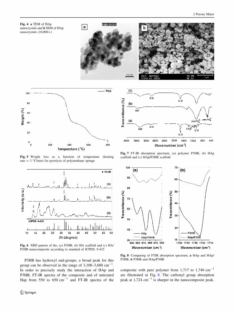
P3HB has hydroxyl end-groups; a broad peak for this
group can be observed in the range of 3,100–3,680 cm-1.
In order to precisely study the interaction of HAp and
P3HB, FT-IR spectra of the composite and of untreated
Hap from 550 to 650 cm-1 and FT-IR spectra of the
composite with pure polymer from 1,717 to 1,740 cm-1
are illustrated in Fig. 8. The carbonyl group absorption
peak at 1,724 cm-1 is sharper in the nanocomposite peak.
Fig. 4 a TEM of HAp
nanocrystals and b SEM of HAp
nanocrystals (10,0009)
Fig. 5 Weight loss as a function of temperature (heating
rate = 3 �C/min) for pyrolysis of polyurethane sponge
Fig. 6 XRD pattern of the, (a) P3HB, (b) HA scaffold and (c) HA/
P3HB nanocomposite according to standard of JCPDS: 9-432
Fig. 7 FT-IR absorption spectrum, (a) polymer P3HB, (b) HAp
scaffold and (c) HAp/P3HB scaffold
Fig. 8 Comparing of FTIR absorption spectrum, a HAp and HAp/
P3HB, b P3HB and HAp/P3HB
J Porous Mater
123
This peak in the HAp/P3HB nanocomposite is shifted to a
lower wave number of 1,721 cm-1, possibly indicating
hydrogen bond formation between P3HB carbonyl groups
and HAp particles. Peaks associated with PO4-3 in both
states of stretching and bending vibration showed that the
low-resolution ratio of these peaks in nanocomposite is
against pure HAp. The wave numbers of these peaks for the
bending vibration are shifted from 574, 598 and 628 cm-1
in pure HAp to 566, 604 and 633 cm-1, respectively, in
nanocomposites (Fig. 8). In terms of PO4-3 stretching
peaks, a wavenumber of 1,025 cm-1 in pure HAp can be
compared to a nanocomposite wavenumber of 1,019 cm-1
attributable to the ceramic matrix of the scaffold. This
evidence demonstrates the presence of HAp in the com-
posite; the change in wavenumber may indicate hydrogen
bond formation among hydroxyl groups, HAp PO4-3 groups
and P3HB carbonyl groups.
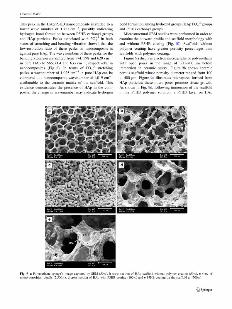
Microstructural SEM studies were performed in order to
examine the outward profile and scaffold morphology with
and without P3HB coating (Fig. 10). Scaffolds without
polymer coating have greater porosity percentages than
scaffolds with polymer coating.
Figure 9a displays electron micrographs of polyurethane
with open pores in the range of 300–700 lm before
immersion in ceramic slurry. Figure 9b shows ceramic
porous scaffold whose porosity diameter ranged from 100
to 400 lm. Figure 9c illustrates micropores formed from
HAp particles; these micro-pores promote tissue growth.
As shown in Fig. 9d, following immersion of the scaffold
in the P3HB polymer solution, a P3HB layer on HAp
Fig. 9 a Polyurethane sponge’s image captured by SEM (509), b cross section of HAp scaffold without polymer coating (509), c view of
micro-porosities’ details (2,5009), d cross section of HAp with P3HB coating (1009) and e P3HB coating on the scaffold at (5009)
J Porous Mater
123
particles is responsible for the scaffold’s high resistance
level; pore size has been reduced to 100–250 lm in
diameter. Figure 9e indicates homogenous P3HB coating
on the ceramic scaffold. FT-IR analysis (Fig. 9d, e) indi-
cates hydrogen bonds [54] between the polymer coating
and ceramic scaffold.
Table 1 indicates the average scaffold density and
porosity with and without P3HB coating; with increasing of
HAp and immersion time, the porosity percentage is
decreased. In a similar study [55], Chen et al. reported a
2.2% decrease in Bioglass macroporosity after coating with
PDLA polymer. The scaffolds gained approximately 12%
weight after coating with P3HB, which may increase
resistance and toughness.
3.3 Compressive strength of HAp scaffold with/
without P3HB coating
Compression impact tests were administered on two types
of HAp scaffold with and without P3HB coating. Results
are listed in Table 2; the compressive strength level of
ceramic scaffolds without polymer coating was 0.11 MPa,
while the compressive strength level of HAp scaffolds with
polymer coating was 1.55 MPa. Table 2 also shows that
increased immersion time increases the mechanical
properties of the scaffold. Ceramic scaffolds sometimes
develop cracks, contributing to a decrease in the mechan-
ical properties level of the scaffold; when immersed in
P3HB, all cracks became filled, and compressive strength
increased significantly.
In other research, Miao et al. coated PLGA onto TCP/
HAp ceramic scaffolds; the compressive strength level and
compressive module were 0.66 and 16.85 MPa, respec-
tively [33]. Tan et al. have coated PLGA-Bioglass onto
HAp ceramic scaffolds and reached compressive strength
and compressive modules of 1.36 and 24.58 MPa, respec-
tively [34].
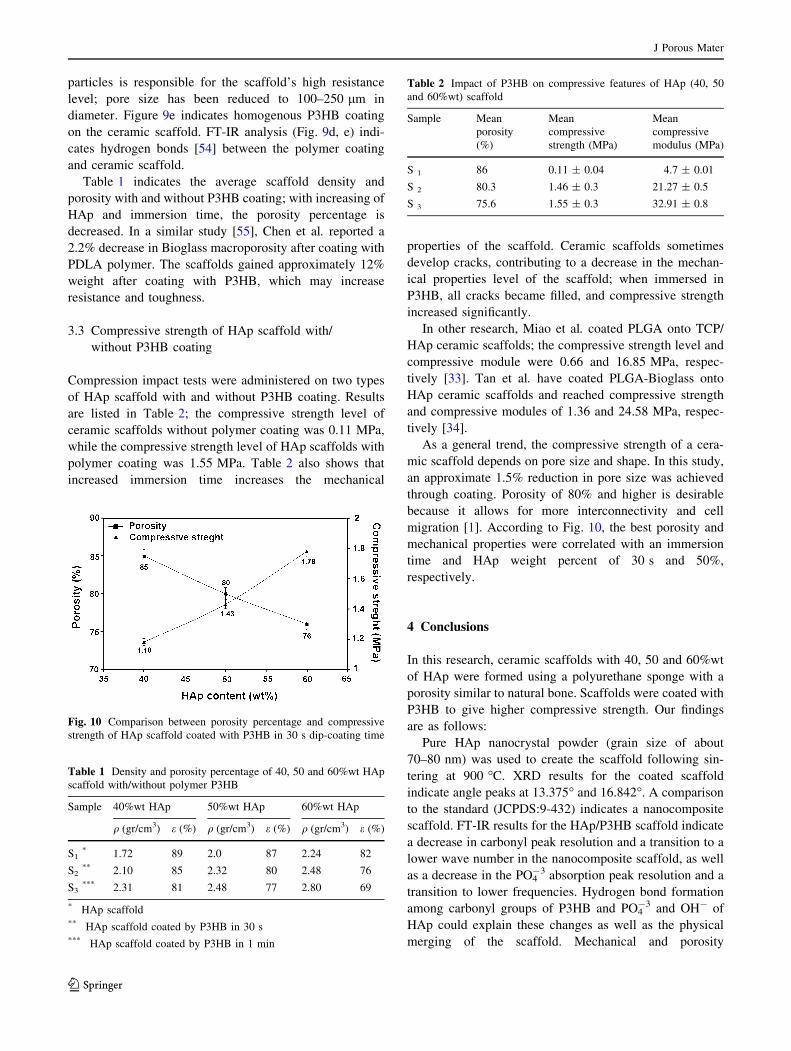
As a general trend, the compressive strength of a cera-
mic scaffold depends on pore size and shape. In this study,
an approximate 1.5% reduction in pore size was achieved
through coating. Porosity of 80% and higher is desirable
because it allows for more interconnectivity and cell
migration [1]. According to Fig. 10, the best porosity and
mechanical properties were correlated with an immersion
time and HAp weight percent of 30 s and 50%,
respectively.
4 Conclusions
In this research, ceramic scaffolds with 40, 50 and 60%wt
of HAp were formed using a polyurethane sponge with a
porosity similar to natural bone. Scaffolds were coated with
P3HB to give higher compressive strength. Our findings
are as follows:
Pure HAp nanocrystal powder (grain size of about
70–80 nm) was used to create the scaffold following sin-
tering at 900 �C. XRD results for the coated scaffold
indicate angle peaks at 13.375� and 16.842�. A comparison
to the standard (JCPDS:9-432) indicates a nanocomposite
scaffold. FT-IR results for the HAp/P3HB scaffold indicate
a decrease in carbonyl peak resolution and a transition to a
lower wave number in the nanocomposite scaffold, as well
as a decrease in the PO4-3 absorption peak resolution and a
transition to lower frequencies. Hydrogen bond formation
among carbonyl groups of P3HB and PO4-3 and OH- of
HAp could explain these changes as well as the physical
merging of the scaffold. Mechanical and porosity
Table 1 Density and porosity percentage of 40, 50 and 60%wt HAp
scaffold with/without polymer P3HB
Sample 40%wt HAp 50%wt HAp 60%wt HAp
q (gr/cm3) e (%) q (gr/cm3) e (%) q (gr/cm3) e (%)
S1* 1.72 89 2.0 87 2.24 82
S2** 2.10 85 2.32 80 2.48 76
S3*** 2.31 81 2.48 77 2.80 69
* HAp scaffold** HAp scaffold coated by P3HB in 30 s*** HAp scaffold coated by P3HB in 1 min
Table 2 Impact of P3HB on compressive features of HAp (40, 50
and 60%wt) scaffold
Sample Mean
porosity
(%)
Mean
compressive
strength (MPa)
Mean
compressive
modulus (MPa)
S 1 86 0.11 ± 0.04 4.7 ± 0.01
S 2 80.3 1.46 ± 0.3 21.27 ± 0.5
S 3 75.6 1.55 ± 0.3 32.91 ± 0.8
Fig. 10 Comparison between porosity percentage and compressive
strength of HAp scaffold coated with P3HB in 30 s dip-coating time
J Porous Mater
123
percentage tests showed that the best weight percentage of
HAp and immersion time are 50%wt and 30 s,
respectively.
Acknowledgments I would like to express my deep gratitude to
Prof. Hamdi, a faculty member of the University of Malaya and Dr.
Rabiee, a faculty member of Nooshiravaani university of Baabol for
their service and generous support which enabled me to conduct this
research.
References
1. R. Lanza, R. Langer, J. Vacanti, Principle of Tissue Engineering,
3rd edn. (Academic Press, London, 2007), pp. 6–7
2. J. Hollinger, T. Einhorn, B. Doll, Ch. Sfeir, Bone Tissue Engi-neering (CRC Press, Boca Raton, 2005), p. 54
3. W. Suchanek, Y. Masahiro, J. Mater. Res. 13, 94 (1998)
4. J. Huang, S.M. Best, W. Bonfield et al., J. Mater. Sci. Mater.
Med. 15(4), 441–445 (2004)
5. L.L. Hench, J. Am. Ceram. Soc. 74, 1487 (1991)
6. S. Pramanik, A.K. Agarwal, K.N. Rai, Trends Biomater. Artif.
Organs. 19, 46 (2005)
7. N. Kivrak, A.C. Tas, J. Am. Ceram. Soc. 81, 2245 (1998)
8. A. Balamurugan, S. Kannan, S. Rajeswari, Trends Biomater.
Artif. Organs. 16, 18 (2002)
9. P. Layrolle, A. Ito, T. Tateishi, J. Am. Ceram. Soc. 81, 1421
(1998)
10. M. Sivakumar, T.S.S. Kumar, K.L. Shantha, K.P. Rao, Bioma-
terials 17, 1709 (1996)
11. D. Shi, G. Jiang, X. Wen, Biomed. Mater. Res. 53, 457 (2000)
12. D. Tadic, M. Epple, Biomaterials 24, 4565 (2003)
13. R. Murugan, K.P. Rao, Trends Biomater. Artif. Organs 16, 43
(2002)
14. S. Sasikumar, R. Vijayaraghavan, Trends Biomater. Artif.
Organs. 19, 70 (2006)
15. K. Prabakaran, A. Balamurugan, S. Rajeswari, Bull. Mater. Sci.
28, 115 (2005)
16. J.H.G. Rocha et al., Bone 37, 850 (2005)
17. J.H.G. Rocha et al., J. Mater. Chem. 15, 5007 (2005)
18. M.K. Herliansyah, E. Pujianto, M. Hamdi, A. Ide-Ektessabi,
M.W. Wildan, A.E. Tontowi, Proceeding of International Con-ference on Product Design and Manufacture, 2006
19. Y.W. Chang, N.J. Kim, C.S. Lee, Mater. Sci. Forum 561, 1441
(2007)
20. C.Y. Ooi, M. Hamdi, S. Ramesh, Ceram. Int. 33, 1171 (2007)
21. J.A. Toque, M.K. Herliansyah, M. Hamdi, A. Ide-Ektessabi,
M.W. Wildan, IFMBE Proceedings of 3rd Kuala Lumpur Inter-national Conference on Biomedical Engineering, vol. 15 (2007),
p. 152
22. A. Ruksudjarit, K. Pengpat, G. Rujijanagul, T. Tunkasiri, Curr.
Appl. Phys. 8, 270 (2008)
23. R. Zhang, P.X. Ma, J. Biomed. Mater. Res. 44, 446 (1999)
24. X. Huang, X. Miao, J. Biomater. Appl. 21, 351 (2007)
25. H.W. Kim, J.C. Knowles, H.E. Kim, J. Biomed. Mater. Res. B 70,
240 (2004)
26. A.J.W. Johnson et al., Biomaterials 28, 45 (2007)
27. X. Miao, L.P. Tan, L. Tan, X. Sand Huang, Mater. Sci. Eng. C 27,
274 (2007)
28. J.M. Oliveira et al., Biomaterials 27, 6123 (2006)
29. R.C. Thomson, M.J. Yaszemski, Biomaterials 19, 1935 (1998)
30. A.R. Boccaccini, J.J. Blaker, V. Maquet, R.M. Day, R. Jerome,
Mater. Sci. Eng. C 25, 23 (2005)
31. A.C. Queiroz, S. Teixeira, J.D. Santos, F.J. Monteiro, Mater. Sci.
Forum 455, 358 (2004)
32. A.C. Queiroz, J.D. Santos, R. Vilar, S. Eugenio, F.J. Monteiro,
Biomaterials 25, 4607 (2004)
33. S. Teixeira, M.P. Ferraz, F.J. Monteiro, J. Mater. Sci. Mater.
Med. 19, 855 (2008)
34. D.M. Yunos, O. Bretcanu, A.R. Boccaccini, J. Mater. Sci. 43,
4433 (2008)
35. X. Miao, D. Meifang, J. Li, Y. Xiao, R. Crawford, Acta Biomater.
4, 638 (2008)
36. D.M.F. Tan, X. Miao, J. Li, Y. Xiao, R. Crawford, J. Biome-
metics, Biomater. Tissue Eng. 1, 99 (2008)
37. I.K. Jun, J. Song, W. Choi, Y. Koh, H. Kim, J. Am. Ceram. Soc.
(2007). doi:10.1111/j.1551-2916.2007.01762.x
38. S. Novak, J. Druce, Q.Z. Chen, A.R. Boccaccini, J. Mater. Sci.
44, 1442 (2009)
39. E. Akaraonye, T. Keshavarz, I. Roy, J. Chem. Technol. Bio-
technol. 85, 732 (2010)
40. S.K. Misra et al., Biomaterials 29, 1750 (2008)
41. Ch.S. Ha, W.J. Cho, Prog. Polym. Sci. 27, 759 (2002)
42. J.C. Knowles, F.A. Mahmud, G.W. Hastings, Clin. Mater. 8, 155
(1991)
43. H. Hajiali, S. Karbasi, M. Hosseinalipour, H. Rezaie, J. Mater.
Sci. Mater. Med. 21, 2125 (2010)
44. O. Bretcanu, Q.Z. Chen, S.K. Misra, I. Roy, E. Verne’, C. Vitale
Brovarone, A.R. Boccaccini, Eur. J. Glass Sci. Technol. A 48,
227 (2007)
45. H.R. Ramay, M. Zhang, Biomaterials 24, 3293 (2003)
46. R. Hodgskinson, J.D. Currey, Proc. Inst. Mech. Eng. H: J. Eng.
Med. 204, 115 (1986)
47. J.D. Curry, Clin. Orthop. Rel. Res. 73, 210 (1970)
48. K.A. Hing, S.M. Best, W. Bonfield, J. Mater. Sci. 10, 135 (1999)
49. P. Shipman, G. Foster, M. Schoeninger, Archaeol. Sci. 11, 307
(1984)
50. E. Landi, A. Tampieri, G. Celotti, S. Sprio, J. Eur. Ceram. Soc.
20, 2377 (2000)
51. A. Boskey, N.P. Camacho, Biomaterials 28, 2465 (2007)
52. K. Haberko et al., J. Eur. Ceram. Soc. 26, 537 (2006)
53. K. Zin-Kook, J.O. Jeong, K. Hisamichi, J. Biomech. Sci. Eng. 4,
377 (2009)
54. R. Murugan, S. Ramakrishna, K. Panduranga Rao et al., Mater.
Lett. 60, 2844 (2006)
55. Q.Z. Chen, A.R. Boccaccini, J. Biomed. Mater. Res. A 77, 445
(2006)
J Porous Mater
123