Phys 531 Lecture 20 1 November 2005...
21
Phys 531 Lecture 20 1 November 2005 Interferometers Last time, described laser beams Explained how they propagate in free space, optical systems Today: Interferometers Practical application of interference 1 Outline: • Review interference • Michelson interferometer • Thin film interference • Fabry-Perot interferometers All from Hecht chapter 9 Next time: interference with incoherent sources 2
-
Upload
trannguyet -
Category
Documents
-
view
216 -
download
0
Transcript of Phys 531 Lecture 20 1 November 2005...
Phys 531 Lecture 20 1 November 2005
Interferometers
Last time, described laser beams
Explained how they propagate
in free space, optical systems
Today: Interferometers
Practical application of interference
1
Outline:
• Review interference
• Michelson interferometer
• Thin film interference
• Fabry-Perot interferometers
All from Hecht chapter 9
Next time: interference with incoherent sources
2
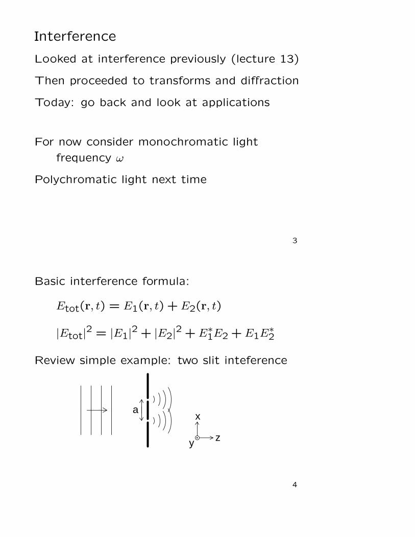
Interference
Looked at interference previously (lecture 13)
Then proceeded to transforms and diffraction
Today: go back and look at applications
For now consider monochromatic light
frequency ω
Polychromatic light next time
3
Basic interference formula:
Etot(r, t) = E1(r, t) + E2(r, t)
|Etot|2 = |E1|
2 + |E2|2 + E∗1E2 + E1E∗2
Review simple example: two slit inteference
ax
z y
4

Setup:
• Slit width b, separation a along x
• Length along y = L: look at y = 0
• Incident amplitude E0
From Fraunhofer formula:
Etot(x,0, d) = −ibL
λdE0 eikd sinc
(
kxb
2d
)
(
1 + e−ikxa/d)
and
|Etot|2 =
(
bL
λd
)2
sinc2(
kxb
2d
)
∣
∣
∣1 + e−ikxa/d∣
∣
∣
2
5
Interference described by |1 + e−ikxa/d|2 term
∣
∣
∣1 + e−ikxa/d∣
∣
∣
2=(
1 + e−ikxa/d) (
1 + eikxa/d)
= 1 + 1 + eikxa/d + e−ikxa/d
= 2 + 2cos
(
kxa
d
)
Cosine term from interference of E1 and E2
Interference phase = kxa/d
6

Get same result from geometrical picture
θ
a
aθ
= x/d
Phase difference between E1 and E2 = kaθ= kxa/d
= argument of interference term
7
Two-slit system is simple interferometer
= device that measures interference between
two (or more) fields
Allows measurement of phase differences:
often useful
Two-slit interference hard to apply
Look at some better techniques
8

Michelson Interferometer (Hecht 9.4.2)
adjust
Heavy black lines = mirror surface
Dashed black line = beamsplitter surface
“Compensation plate” makes arms equivalent
9
At output, see two sources
reflection from each mirror
Interference pattern depends on
- mirror positions
- real source location
Mirror tilted:
- sources displaced horizontally
Arm lengths different:
- sources displaced vertically
10
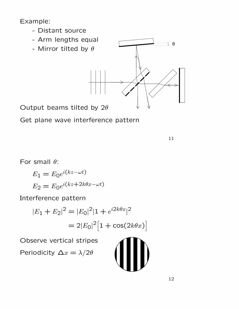
Example:
- Distant source
- Arm lengths equal
- Mirror tilted by θθ
Output beams tilted by 2θ
Get plane wave interference pattern
11
For small θ:
E1 = E0ei(kz−ωt)
E2 = E0ei(kz+2kθx−ωt)
Interference pattern
|E1 + E2|2 = |E0|
2|1 + ei2kθx|2
= 2|E0|2[
1 + cos(2kθx)]
Observe vertical stripes
Periodicity ∆x = λ/2θ
12

Call stripes “fringes”
As θ → 0 central fringe expands to fill output
If mirrors not perfectly flat,
get wavy pattern from mirror distortion
Useful for testing mirrors
What if we also adjust position of mirror?
Offset position by d
13
d
For small θ, upper arm length increases by 2d
14

2θ
x = 0
2d Effect on pattern:
E1 = E0ei(kz−ωt)
E2 = E0ei(kz+kxθ+2kd−ωt)
Get
|Etot|2 = 2|E0|
2[
1 + cos(2kθx + 2kd)]
Peaks at 2kxθ + 2kd = 2πm
integer m
xm =1
θ
(
mλ
2− d
)
15
Peaks slide across field as d changes
As θ → 0, pattern is uniform- oscillates between bright and dark with d
Periodicity in d: 2k∆d = 2π
∆d =λ
2Change d by λ/4, output changes bright → dark
Easy to visualize how waves interfere:
E1E2
2d
16
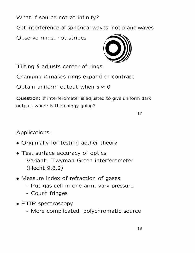
What if source not at infinity?
Get interference of spherical waves, not plane waves
Observe rings, not stripes
Tilting θ adjusts center of rings
Changing d makes rings expand or contract
Obtain uniform output when d ≈ 0
Question: If interferometer is adjusted to give uniform dark
output, where is the energy going?
17
Applications:
• Originially for testing aether theory
• Test surface accuracy of optics
Variant: Twyman-Green interferometer
(Hecht 9.8.2)
• Measure index of refraction of gases
- Put gas cell in one arm, vary pressure
- Count fringes
• FTIR spectroscopy
- More complicated, polychromatic source
18

Other Interferometers
Sagnac →
Beams travel same path
Senstive to rotations
← Mach-Zehnder
Completely independent paths
Used as fiber optics switch
19
Parallel Plate Interferometer (Hecht 9.4.1)
Very simple setup:
Plane wave incident on glass plate
E1
E2
θ
d
Look at interference
of reflected beams
20
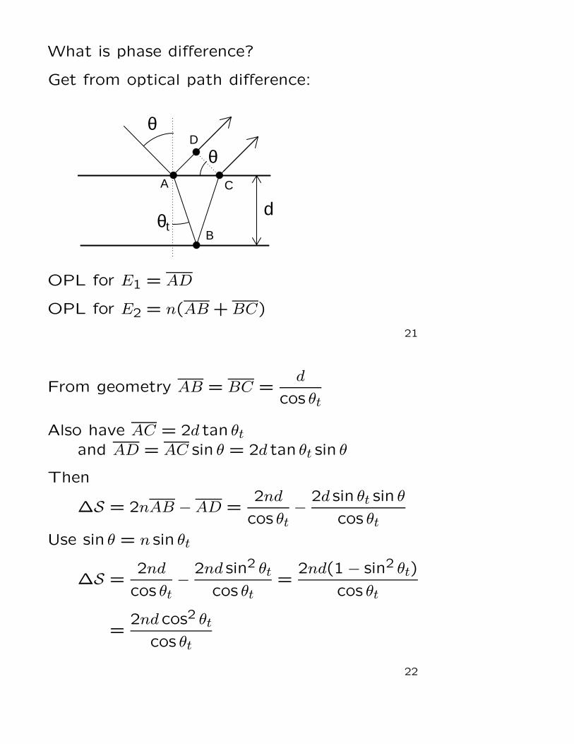
What is phase difference?
Get from optical path difference:
θ
dθt
A
B
C
D
θ
OPL for E1 = AD
OPL for E2 = n(AB + BC)
21
From geometry AB = BC =d
cos θt
Also have AC = 2d tan θt
and AD = AC sin θ = 2d tan θt sin θ
Then
∆S = 2nAB −AD =2nd
cos θt−
2d sin θt sin θ
cos θt
Use sin θ = n sin θt
∆S =2nd
cos θt−
2nd sin2 θt
cos θt=
2nd(1− sin2 θt)
cos θt
=2nd cos2 θt
cos θt
22

So ∆S = 2nd cos θt = 2d√
n2 − sin2 θ
However, get additional phase shift from reflection
Fresnel relations: if no TIR,
π phase shift for internal vs. external reflection
Then |Etot|2 = |E0|
2∣
∣
∣1− eik∆S∣
∣
∣
2
= 2|E0|2[
1− cos(2nkd cos θt)]
23
Note reflected power ∝ |Etot|2 oscillates with θ
Zero when
cos θt =2πm
2nkd=
mλ
2ndfor integer m
Note interference depends on λ
Reason why oil films, soap bubbles look colored:
For some θ, blue light has a maximum
and red light has a minimum
Question: Why don’t we see colors in light reflected from
ordinary glass windows?
24

Note if θ = 0, then θt = 0
No reflection when 2nd = mλ
or d = mλ′
2
λ′ = wavelength in medium
Simple picture:
d
Perfect transmission when wavelengths “fit” medium
- standard resonance condition
25
Use this idea for anti-reflection coating
d
air
glass
MgF2
Put layer of MgF2 on glass air interface
n = 1.38
Get reflection from both surfaces,
set thickness so that waves cancel
Amplitudes E1 and E2 not equal: get R ≈ 1%
- do better with multiple layers (Hecht 9.7)
26
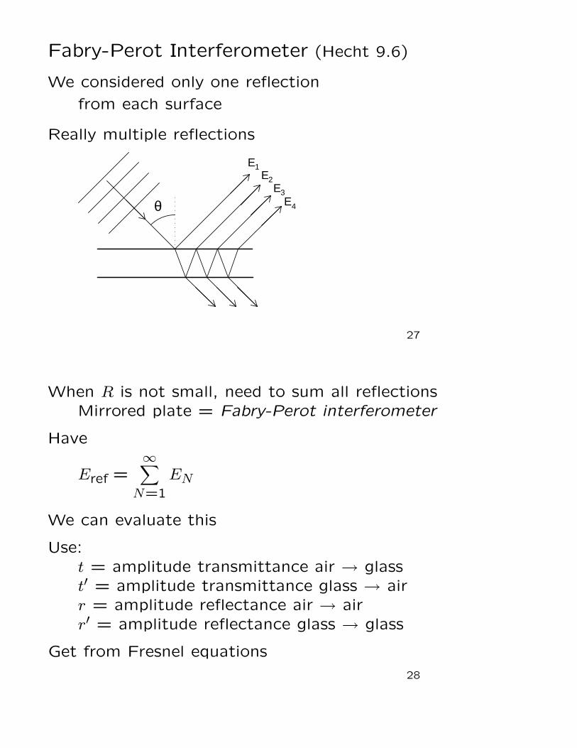
Fabry-Perot Interferometer (Hecht 9.6)
We considered only one reflection
from each surface
Really multiple reflections
E1
θ
E2E3
E 4
27
When R is not small, need to sum all reflections
Mirrored plate = Fabry-Perot interferometer
Have
Eref =∞∑
N=1
EN
We can evaluate this
Use:
t = amplitude transmittance air → glass
t′ = amplitude transmittance glass → air
r = amplitude reflectance air → air
r′ = amplitude reflectance glass → glass
Get from Fresnel equations
28

Look at each term
Suppose incident field E0
First reflection just reflects air → air: E1 = rE0
Second reflection:
transmit air → glass: t
reflect glass → glass: r′
transmit glass → air: t′
Also acquires phase eiδ with δ = 2nkd cos θt
So E2 = tr′t′eiδE0
29
Third reflection:
Like E2 but two additional reflections r′
and additional phase shift eiδ
So E3 = tr′3t′e2iδE0
Get additional factor of (r′)2eiδ for each order
Generally
EN = tt′ (r′)2N−3 e(N−1)iδ E0
(but N = 1 is special)
30

So total reflected field is
Eref =[
r + tt′r′eiδ(
1 + r′2eiδ + r′4e2iδ + . . .)]
E0
Terms in parentheses are geometric sum:
1 + r′2eiδ + r′4e2iδ + · · · =∞∑
N=0
xN
for x = r′2eiδ
Then
∞∑
N=0
xN =1
1− x=
1
1− r′2eiδ
31
So
Eref =
(
r +tt′r′eiδ
1− r′2eiδ
)
E0
Can simplify further:
Still have r′ = −r
Also, for nonabsorbing medium have tt′ = 1− r2
Can prove from Fresnel, or see Hecht 4.10
Substitute, get
Eref =
[
r −(1− r2)reiδ
1− r2eiδ
]
E0
32
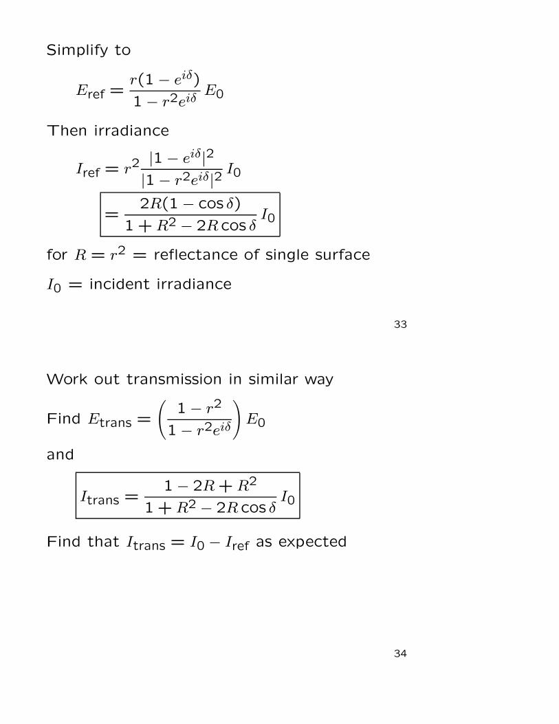
Simplify to
Eref =r(1− eiδ)
1− r2eiδE0
Then irradiance
Iref = r2|1− eiδ|2
|1− r2eiδ|2I0
=2R(1− cos δ)
1 + R2 − 2R cos δI0
for R = r2 = reflectance of single surface
I0 = incident irradiance
33
Work out transmission in similar way
Find Etrans =
(
1− r2
1− r2eiδ
)
E0
and
Itrans =1− 2R + R2
1 + R2 − 2R cos δI0
Find that Itrans = I0 − Iref as expected
34

Recall δ = 2nkd cos θm
depends on d, λ, θ
Plot Itrans/I0 as function of δ
35
Transmission = 1 when δ = 2πm
Same condition for reflection = 0 in original calc
Peaks narrower for higher R:
For R ≈ 1, full width at half-max = 2(1−R)
Can get R up to 0.99999
Very narrow transmission peaks:
useful for spectroscopy
36
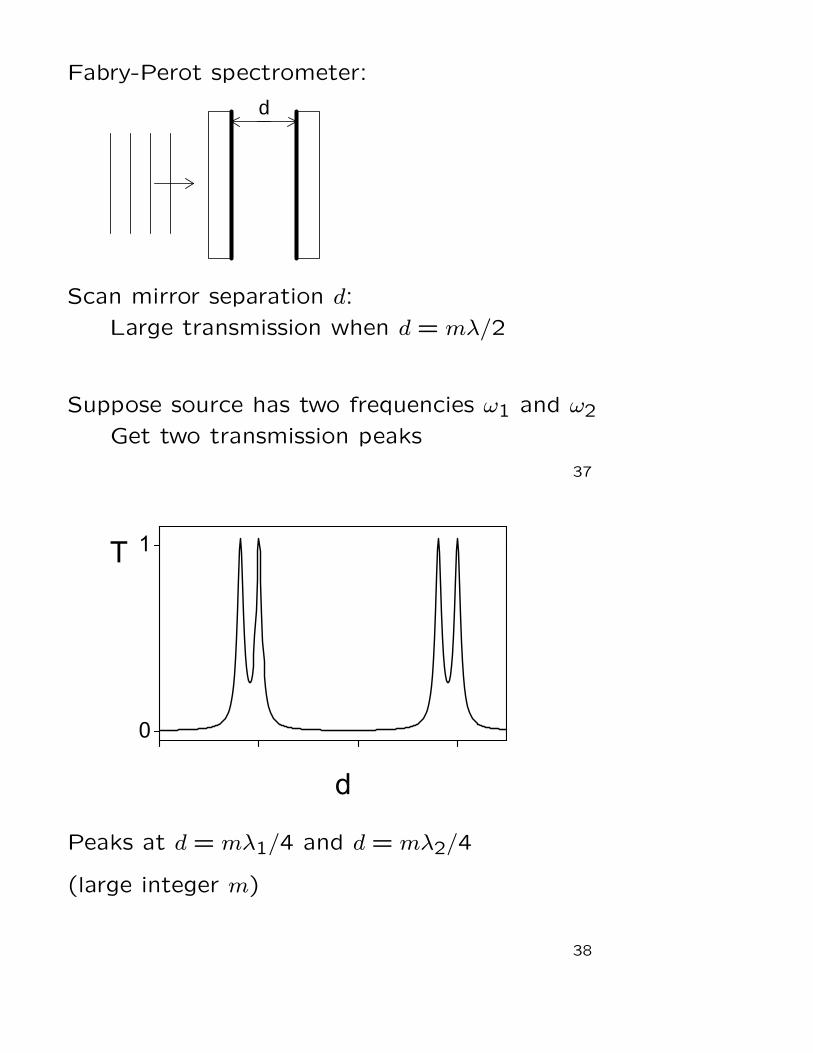
Fabry-Perot spectrometer:
d
Scan mirror separation d:
Large transmission when d = mλ/2
Suppose source has two frequencies ω1 and ω2
Get two transmission peaks
37
Peaks at d = mλ1/4 and d = mλ2/4
(large integer m)
38
Peaks resolved if δ1 − δ2 > ∆ ≈ 2(1−R)where δ1 = 2k1d and δ2 = 2k2d
Need k1 − k2 >1−R
d
or ω1 − ω2 > (1−R)c
d
If R = 0.999 and d = 3 cm, get ∆ω = 107 rad/sor ∆ν = 1.6 MHz
This is incredible resolution:
Optical frequency = 6× 10¹⁴ Hzso ∆ν/ν ≈ 10−9
39
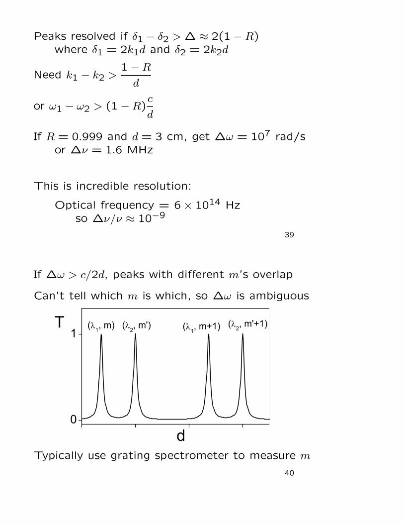
If ∆ω > c/2d, peaks with different m’s overlap
Can’t tell which m is which, so ∆ω is ambiguous
Typically use grating spectrometer to measure m
40
Summary:
• Interferometer = device that measures phase
• Michelson: beamsplitter, mirrors control light
• Thin plate: two-beam interference
Can eliminate reflection
• Fabry-Perot: multiple-beam interference
Useful for spectroscopy
41