Photovoltaic Solar Cells for Outdoor LiFi Communications
11
HAL Id: hal-02901381 https://hal-amu.archives-ouvertes.fr/hal-02901381 Submitted on 17 Jul 2020 HAL is a multi-disciplinary open access archive for the deposit and dissemination of sci- entific research documents, whether they are pub- lished or not. The documents may come from teaching and research institutions in France or abroad, or from public or private research centers. L’archive ouverte pluridisciplinaire HAL, est destinée au dépôt et à la diffusion de documents scientifiques de niveau recherche, publiés ou non, émanant des établissements d’enseignement et de recherche français ou étrangers, des laboratoires publics ou privés. Photovoltaic Solar Cells for Outdoor LiFi Communications N. Lorriere, N. Betrancourt, M. Pasquinelli, G. Chabriel, J. Barrere, L. Escoubas, J.-L. Wu, V. Bermudez, C.M. Ruiz, J.-J. Simon To cite this version: N. Lorriere, N. Betrancourt, M. Pasquinelli, G. Chabriel, J. Barrere, et al.. Photovoltaic Solar Cells for Outdoor LiFi Communications. Journal of Lightwave Technology, Institute of Electrical and Electron- ics Engineers (IEEE)/Optical Society of America(OSA), 2020, pp.1-1. 10.1109/JLT.2020.2981554. hal-02901381
Transcript of Photovoltaic Solar Cells for Outdoor LiFi Communications

HAL Id: hal-02901381https://hal-amu.archives-ouvertes.fr/hal-02901381
Submitted on 17 Jul 2020
HAL is a multi-disciplinary open accessarchive for the deposit and dissemination of sci-entific research documents, whether they are pub-lished or not. The documents may come fromteaching and research institutions in France orabroad, or from public or private research centers.
L’archive ouverte pluridisciplinaire HAL, estdestinée au dépôt et à la diffusion de documentsscientifiques de niveau recherche, publiés ou non,émanant des établissements d’enseignement et derecherche français ou étrangers, des laboratoirespublics ou privés.
Photovoltaic Solar Cells for Outdoor LiFiCommunications
N. Lorriere, N. Betrancourt, M. Pasquinelli, G. Chabriel, J. Barrere, L.Escoubas, J.-L. Wu, V. Bermudez, C.M. Ruiz, J.-J. Simon
To cite this version:N. Lorriere, N. Betrancourt, M. Pasquinelli, G. Chabriel, J. Barrere, et al.. Photovoltaic Solar Cells forOutdoor LiFi Communications. Journal of Lightwave Technology, Institute of Electrical and Electron-ics Engineers (IEEE)/Optical Society of America(OSA), 2020, pp.1-1. 10.1109/JLT.2020.2981554.hal-02901381
1
Photovoltaic Solar Cells for Outdoor LiFiCommunications
N. Lorrière, N. Bétrancourt, M. Pasquinelli, G. Chabriel, J. Barrère, L. Escoubas, J.-L. Wu, V. Bermudez, C. M.Ruiz and J.-J. Simon
Index Terms—Visible Light Communication (VLC), LiFi, Solarmodules, Solar cells, DC biased Optical - Orthogonal FrequencyDivision Multiplexing (DCO-OFDM), indoor/outdoor applica-tions
Abstract—Increasing demand of wireless devices contributes toradiofrequency (RF) congestion. Light Fidelity (LiFi) promisesto be an interesting alternative by using the visible part of theelectromagnetic spectrum instead of the RF part as nearly allexisting wireless transmission systems do.A basic LiFi system is composed of one intensity-controlled light-emitting diode (LED) and one receiver device sensitive to veryhigh-frequency (thus invisible to human sight) modulations of theluminous intensity. In most cases, the photoreceptor is a siliconphotodiode of PIN (P-type intrinsic N-type) or APD (Avalanchephotodiode) conception. Recently, a few studies suggest thatphotovoltaic (PV) modules could be used to implement outdoorLiFi transmissions, i.e., under direct sunlight exposure.In this paper, we propose to compare the behavior of a PVmodule and a commercial APD-based photodetector (without anyoptical lens or colored filter) for experimental LiFi transmissionson both indoor and outdoor conditions. The performance ofthe two solutions is quantified in terms of various frequencyresponses like attenuation, signal-to-noise ratio, or bit-error rate.The results show that, while the photodiode exhibits very goodperformance in indoor conditions, its frequency response israpidly deteriorating when a sunlight exposure of more than200W/m2 is superimposed over the LiFi signal. We demonstratethat a PV module in Voc (open-circuit voltage) condition stilloperates a LiFi transmission under additional solar illumination.
I. INTRODUCTION
The rapid and massive demand-led growth for communica-tion frequencies created by wireless devices (from a simpleremote control to automatic vehicles [1], through all comingsoon Internet of Things (IoT) and smartphones) is leading toa Radio Frequency (RF) spectrum “bottleneck,” increasing thedifficulty of finding available bandwidth. At the same time,blue Light Emitting Diode (LED) has gained a huge interestsince its discovery in 1972 until its intensity reached one
N. Lorrière, M. Pasquinelli, L. Escoubas, C. M. Ruiz, and J.-J. Si-mon are with Aix Marseille Univ, Univ Toulon, CNRS, IM2NP, Mar-seille, France (e-mail: [email protected]; [email protected]; [email protected]; [email protected]; [email protected]).
N. Bétrancourt was in an internship at Aix Marseille Univ, Univ Toulon,CNRS, IM2NP, Marseille, France (e-mail: [email protected]).
G. Chabriel and J. Barrère are with Univ Toulon, Aix MarseilleUniv, CNRS, IM2NP, La Garde, France (e-mail: [email protected];[email protected]).
J.-L. Wu and V. Bermudez are with Atsugi Research Center, Solar Fron-tier K.K., Atsugi, Kanagawa 243-0206, Japan (e-mail: [email protected]; [email protected]).
candela in 1993 [2]. It will ultimately replace conventionallighting systems over the coming years.In this context, Visible Light Communication (VLC), understandardization since 2011 [3], would offer a novel alternativeto RF communications. For example, and as an application,LiFi (Light Fidelity - a term coined by Harald Haas in2011 [4]) technology would complement the WiFi systems toremedy the lack of RF channels reusing the existing lightinginfrastructure. In the context of LiFi, light is emitted by a LEDand detected by a single photodetector which converts the lightintensity high-frequency variations (invisible to the humaneye) into an electrical signal. These kinds of systems arereferred to as Intensity-Modulated/Direct-Detection (IM/DD)systems.In IoT applications, a high data-rate is generally not required,and the use of receivers with a bandwidth of some hundredsof kHz to MHz is often sufficient [5]. In addition, the authorsin [6] claim that most applications in energy management,health and security systems, only require a data rate of lessthan 1 Mbps. In an other hand, low power consumption andhigh reliability in indoor or outdoor conditions will also berequired for near future VLC applications like e.g., Vehicle-to-Infrastructure (V2I) and Vehicle-to-Vehicle (V2V) [1]. Wepropose here to compare the performance of two kinds ofLiFi photodetectors (photodiodes and PV modules) intended tooptical wireless communication systems in indoor and outdoorenvironments.
The implementation of photodiodes (PD) as VLCphotoreceivers raises a major drawback: PD-basedphotoreceivers face a problem of performance reductionunder sunlight exposure [7], [8]. Despite this, Islim et al. [9],[10] showed that it was possible to establish communicationsunder solar irradiation by using a blue LED emitter, a bluefiltered APD receiver and an additional lens focusing theLED light beam towards the APD.
On the other hand, PV cells are optimized for outdoorsenergy harvesting, making them potential candidates for useas VLC receivers in outdoor applications. This study thusaims to check if PV modules can be used and outmatchPD’s performance as VLC receivers in both indoor andoutdoor conditions. Moreover, the possibility to combineenergy harvesting and data communication has been alreadydemonstrated [11], [12], highlighting the interest of PVmodules for self-powered IoT device design.
Most of outdoors optical communications (called FSO forFree-Space Optical communication) use laser-emitters, and

2
some of them use a PV receiver [13], [14], [15]. However,to the best of our knowledge, only a few publications addressLED-based VLC with PV modules as receivers [16], [17],[18], [19], [20], and none shows a data communication inreal outdoor conditions. This work compares experimentalperformance obtained by a PV-based receiver and a PD-basedreceiver with a large range of solar irradiation levels andwithout any lens or color filter to improve the strength of theinformation signal. The data are sent from a standard whiteLED light source. Note that comparison with blue-LED/blue-filter systems remains an open problem.
The remainder of the paper is structured into five sections:the following section II puts in balance physical characteris-tics of photodiodes and PV modules with the VLC receiverrequirements. The VLC experimental setup we developed ispresented in section III. Section IV compares, in indoor condi-tions, the frequency bandwidth of a popular photodiode-basedphotoreceiver (Hamamatsu APD module C12702-12) with thatof a high-efficiency CIGSa based solar module provided bySolar Frontier company. The APD and PV performance isthen evaluated in terms of gain, bandwidth, and BER in realoutdoor conditions. Finally, the last Section V gives a generalconclusion, including perspectives.
II. PHOTORECEIVERS ELECTRICAL MODELLING
To operate outdoors, a VLC receiver has to detect smalllight variations broadcast by the emitting LED while beingsubject to a dominant DC illumination due to sunlight. In whatfollows, we review the pros and cons of using a photodiodeor a PV module for VLC.
A. VLC reception by a photodiode
Currently, all VLC commercial solutions use photodiode-based devices as photoreceivers. PD are able to detect low-level light variations. This performance is due to the highquality of current microelectronics-grade silicon combinedwith the use of a high gain transimpedance amplifier (TZ)to obtain a voltage output ready for sampling (see Fig. 1).In addition to the amplifying effect, the TZ is designed tomaintain the anode voltage at a constant level (a zero voltagein the example in Fig. 1) to ideally shunt all photocurrentIPH through the feedback resistance Rf . The PD’s transientcapacitor, already reduced by the high reverse voltage, tendsto be bypassed, enhancing the cutoff frequency of the device,which becomes (theoretically) only limited by that of the TZ.
Currently, two types of photodiodes are used for VLCapplications:
• silicon PIN photodiodes: an intrinsic region is insertedbetween the two doped regions increasing the volumewhere an incident photon can generate electron-holepairs,
• silicon avalanche photodiodes APD: a high reverse biasis applied to increase the electric field and therefore thevelocity of carriers responsible for the avalanche effect.
aCIGS: Copper Indium Gallium Selenide - A thin-film technology of solarcells.
Fig. 1. PD - TZ basic circuit (photoconductive mode)
Due to the avalanche phenomenon, APD exhibits a higher pho-tosensibility compared to a PIN photodiode. As the TZ gaindecreases with decreased feedback resistor Rf (see Fig.1), alower value of Rf conducts to a higher bandwidthb, APDis then expected to give a higher bandwidth rather than PINphotodiodes [21].In the literature, due to its superior quantum efficiency, one canoften read that using an APD is more effective in improvingthe SNR than PIN diodes (see e.g. [7]), particularly at lowoptical powers (see [22], p.70). But it seems that this may notalways be the case for high optical powers [23].
Note that the very small active areas of standard photodiodescan lead to light halo mismatch or shading effects.
One can then outline the following “benefits vs. drawbacks”for the use of a PD-based device as VLC receiver (comparedto PV modules):
• Benefits:– high bandwidth,– the output voltage has a linear variation with the
illumination (VOUT proportional to IPH , see Fig. 1),– the avalanche phenomenon improves detection of small
light intensity variations.
• Drawbacks:– small detection surface,– the need for a very high performance amplifier circuit
(high cost) i.e. low noise and high gain-bandwidthproduct.
B. VLC reception by an open-circuit PV module
Usually, PV cells are connected in series to make moduleswhose the open-circuit output voltage (Voc) can be directlyused to detect light modulations without any transimpedanceamplifier or additional power supply.
1) Solar cell: The conventional one-diode electrical equiv-alent model of a PV [24] presented in Fig. 2 is suitable onlyfor static (DC) signals.
The different elements of the equivalent circuit are asfollows:
bgain-bandwidth product conservation.

3
Fig. 2. Equivalent electrical circuit of a PV cell (DC) [24]
• photocurrent generator IPH : the electron-hole pairs gen-erated by light are swept away by drift in the depletionregion, then collected by diffusion from the undepletedregions,
• diode D: the dark current ID mainly corresponds to dif-fusion phenomena inside the forward-biased p-n junction,
• shunt resistance Rsh: a resistance which corresponds toleakage currents due to metallic impurities in the junction,cristal lattice defaults [25], and potential current leakageson the module edges. The corresponding resistance isgenerally high (several kΩ)
• lumped series resistance Rs: a resistance due to busbars,contact interfaces, and semiconductors conductivity.
In the ideal case Rsh is taken to be near infinite thenthe current through Rsh approaches zero and consequentlyID ≈ IPH . From the Shockley diode equation, it comes, atlow frequency:
VOC = nVT ln
(IPHIs
+ 1
), (1)
where:• n is the ideality factor of the junction,• VT is the thermal voltage (proportional to absolute tem-
perature T ),• Is is the reverse saturation current.
Let us consider now that the photocurrent IPH involves a DCcomponent (Iph) and AC small variations (iph), with iph Iph. To represent the AC behavior of the receiver, one canreplace the forward-biased diode D by its dynamic model. Itembeds a dynamic resistance:
rd =nVTIph
, (2)
and a dynamic capacity (diffusion capacity):
Cd =Iphτ
nVT=
τ
rd, (3)
where the parameter τ represents the effective minority-carrierlifetime.One obtains the linearized equivalent circuit [26] in Fig. 3modeling the small variations of the open-circuit voltage (voc)as a function of the small variations of the photocurrent (iph).Note that this model does not take into account the possibleexistence of trapped charge carriers in the material structure.In [16], the wire connections are more accurately modeled
by adding a small inductance (typically a few tens of nH)in the output branch of the model, i.e., in series with theresistance Rs. When the PV module is highly loaded, thisslightly inductive effect introduces a HF additional pole in thetransfer function. It can be ignored here, given the small loadsand the small bandwidths we consider in this study.
Fig. 3. Equivalent electrical circuit of a PV cell (AC small-signal linearization)[26]
With rd Rsh and rdCd = τ (see (2) and (3)), the fol-lowing frequency transimpedance response T1(f) is obtainedfor a PV cell on open-circuit conditions:
T1(f) ,vFoc(f)
iFph(f)≈ rd
1 + j2πrdCdf=
rd1 + j2πτf
=K
1 + j ffc
,
(4)where the superscript .F denotes the Fourier transform.
The corresponding transfer function is then equivalentto that of a first-order lowpass filter whose static gain isK = rd, and the -3dB cutoff frequency is fc = 1
2πτ . Equation(2) shows that the gain tends to decrease with increasedDC illumination and to increase with the temperature. Thebandwidth is also expected to be, to a lesser extent, bothtemperature and injection level dependent since it is fullydetermined by the lifetime τ [27].
This latter result calls the following important comment:since the efficiency of a solar cell (in terms of energyharvesting) increases with the minority-carrier lifetime [28],one cannot expect to obtain a high bandwidth photoreceiverfrom an efficient PV cell operating in open-circuit conditions.
2) Solar module: A solar module generally corresponds toseveral solar cells connected in series in order to get higheroutput voltage.
Figure 4 represents, in the frequency domain, the small-signal equivalent circuit of a PV module built from N identicalcells. To simplify, each cell is here assumed to be subjectedto the same illumination. Moreover, the complex impedanceZeq(f) is equivalent to that of the two dynamic parameters (rdand Cd) of one cell connected in parallel: Zeq(f) = rd/(1 +j2πτf).
Considering that vFoc(f) = NZeq(f)iFph(f), the VOC fre-quency response TN (f) of a N cells PV module is given by:
TN (f) = NZeq(f) =Nrd
1 + j2πτf. (5)

4
Fig. 4. Equivalent electrical circuit of a PV module (AC small-signallinearisation)
Equation (5) is similar to that of a single solar cell (sameorder and same cutoff frequency) except for the static gain,which is multiplied by the number N of cells.
As a conclusion, an analysis of the “benefits vs. drawbacks”for the use of a PV-based device as VLC passive receiver canbe summed up as follows.
• Benefits:– self-powered (neutral energy) LiFi receiver, allowing
both energy harvesting and LiFi signals detection,– wide detection surface, allowing both to resist to a
partial shading and to get an angular acceptance widerthan with photodiodes.
• Drawbacks:– low bandwidth, due to the time constant τ = rdCd
which is not bypassed here (Voc condition) as in thecase for photodiodes by means of a TZ,
– limited range of the received light variations: accordingto the logarithmic variation of VOC as a function of theillumination (equation 1), the received light variationsiph must remain reasonably low to maintain a near-linear relation with the output voltage variation voc.
III. EXPERIMENTAL SETUP DESCRIPTION
A. LiFi test bench
The LiFi test bench developed at IM2NP is presented in Fig.5. All indoor LiFi characterizations are performed in a darkFaraday cage protecting the measurements from perturbinglights or RF radiations.
In this set-up, the emitting LED sends a sequence of OFDM(orthogonal frequency division multiplexing) symbols. OFDMsignals are widely used in wireless digital transmissions dueto their optimal spectral efficiency and their ability to dealwith non-flat transmission channels (as is the case here).For optical systems, several OFDM versions exist [29], [30].The light intensity modulation chosen in this work is a DCbiased optical (DCO) OFDM, with a cyclic prefix (CP). CPduration has to be chosen greater than or equal to the channelimpulse response duration in order to guarantee steady-statechannel measurements (e.g., about 3.3τ for a PV module).These CP-DCO-OFDM signals have here a dual function:
they allow the estimation of various spectral characteristics(gain, SNR, noise PSD...) of the receiver and, therefore, tosimultaneously evaluate the transmission performance e.g.in term of bit-error rate (BER). Moreover, the very shortmeasurement duration (40 milliseconds), is here particularlysuitable for outdoor experiments, ensuring that the sunlightexposure remains at an almost constant level.In this study, data are broadcast by a 24 blue LED moduleovercoated with a large phosphor layer. This module isreferenced as Philips Lumileds Luxeon CoB Core RangeG3 L2C5-40901202E0900 and we have measured a cutofffrequency of 1.03 MHz. At the receiving end, the APDHamamatsu photodetector is directly connected by acoax cable to the digital oscilloscope for analog-to-digitalconversion (ADC) while high-frequency point probes areused with the Solar Frontier PV module (Fig. 5 and Fig. 12).
A complete description of the bench (hardware and signals)can be found in [31].
B. Description of the transmission parameters
The transmission parameters used to compare the perfor-mance of the two receivers are given in Table I, where a)summarizes the CP-DCO-OFDM signal characteristics, andb) gives the hardware parameters. Note that the maximumfrequency Fmax of the outdoor use signal is chosen lowerthan the indoor use one because of the noise.
TABLE ITRANSMISSION PARAMETERS
a) CP-DCO-OFDM signal parametersNumber of sent symbols Ns 96
Oversampling factor 10Number of payload subcarriers Nc 255
Guard interval size (SGI ) 1 OFDM symbolComplex data constellation map 4-QAM (M = 4)
Minimum frequency Fmin 4.88 kHz out / 195 kHz inMaximum frequency Fmax 1.25 MHz out / 5 MHz in
b) Hardware parametersT/R distance 23 cm
Luminous intensity of LED polarization 5080 luxMaximum luminous modulation 3135 lux
AC Generator 10 VppDC Generator 200 mA
With these parameters, the (maximum) data rate (DR) isgiven by
DR =Fmax log2(M)
(1 + SGI), (6)
where M represents the modulation order and SGI a fractionof the OFDM symbol duration. DR reaches 1.25 Mbps inoutdoor conditions (5 Mbps indoor).
In what follows, the estimation of the photoreceivers spec-tral response H (see [31] for mathematical expression), andthe BER (given by the number of wrong bits over the wholenumber of bits sent) will be measured under different irradia-tion levels.

5
Fig. 5. IM2NP’s LiFi test bench (indoor condition)
The frequency BER function (i.e. BER(f)) is here definedas the ratio between the number of wrong bits Nwb (the num-ber of misallocated bits) received at frequency f , and the cor-responding number of transferred bits Ntb. The BER(f) fre-quency resolution is the lowest quantifiable value of BER(f),which is to say corresponding to a single misallocated bit(Nwb = 1). The BER(f) frequency resolution is given by1Ntb
= 1Ns log2(M) . It is equal to 1
96×2 = 5.10−3 for ourmeasurements. For the chosen modulation, better resolutionsand smoother frequency BER functions could be reached byincreasing the number of symbols Ns (i.e., the measurementduration). Here we decided to set the measurement duration to40 ms (40ms = (1 + SGI)NsF
−1min where SGI ,Ns and Fmin
values are taken from table I) ensuring the solar irradiationstability.
C. Receiver devices description
The avalanche photodiode (APD) tested here is a "Hama-matsu APD Module C12702-12". As shown in Fig. 6, theemission spectrum of the LED is fully covered by the spectralsensitivity range of the Hamamatsu APD [32]. The emissionspectra of the LED (continuous blue linec) and sun (dashedgreen lined) correspond to the integral of their spectral irradi-ance on the APD active surface. The flat spectral responseHAPD for the light intensity modulation between 10kHzand 20MHz of this APD [32] allows the calibration of thetransmitting device (LED and BiasT).
cmeasurement obtained from a VISO BaseSpion goniophotometer.dAM1.5 for Air Mass 1.5 is the most common standard of solar spectral
irradiance utilized to quantify the performance of solar cells on earth. It isroughly valid for mid-latitude positions on earth. The ASTM G-173 standard[33] defines it.
Fig. 6. Hamamatsu APD spectral response (DataSheet [32]) compared to fluxreceived by the photodiode, provided by the LED (IM2NP measurement) andthe sun.
A first measurement of the transfer function Hcal(f) for thewhole bench, including LED, Bias-T and Hamamatsu APDis performed indoor (in a darkroom), for frequencies f takenbetween 40 kHz and 5 MHz:
Hcal(f) = HLED(f)HBiasT (f)HAPD
In these conditions, the shape of Hcal(f) is due to the LEDand the BiasT. Hcal(f) can then be used to compensatefor the LED and BiasT offset in the raw transfer functionmeasurement of any other photoreceivers Hraw(f). Thus, thecalibrated transfer function of any receivers Hrec(f) is givenby
Hrec(f) = Hraw(f)Hcal(f)
or Hrec [dB](f) = Hraw [dB](f) −Hcal [dB](f),

6
with H[dB] = 20 log10(H) and 40kHz ≤ f ≤ 5MHz.
The PV module (provided by Solar Frontier company) iscomposed of 13 CIGS cells with an anti-reflecting coating.The I(V) curve on AM1.5 condition is represented in Fig. 7.Other intrinsic characteristics and useful static parameters arelisted in Table II.
Fig. 7. Solar Frontier PV module I(V) curve (measurements from SolarFrontier company)
TABLE IISOLAR FRONTIER PV MODULE CHARACTERISTICS
Number of cells 13Short circuit current (mA) 80.5Open circuit voltage (V) 7.82
Fill Factor (%) 70.96Area (cm2) 26.05
Current density at short circuit (mA/cm2) 3.09Series resistance (Ω) 12.51Shunt resistance (Ω) 3694.70
Efficiency (%) 17.15
Similar to the APD device, Fig. 8 shows that both LEDand solar spectrum are within the spectral sensibility rangeof the Solar Frontier PV module. The scale differences ofthe blue curves in Fig. 6 and Fig. 8 are due, first, to thedifferences between the receiver’s active areas, and also, tothe inhomogeneity of the LED radiation pattern. The sunpower irradiation received on a photoreceiver varies as a directfunction of its area. Due to the directivity of its radiationpattern, it is not true for the LED: the PV photoreceiverhaving a large surface, the power received from the LEDis concentrated in its central area (halo) while it remainshomogeneously distributed over the small area of the APD.It follows that the PV module receives 14.6% of the LEDpower on 26.05 cm2 since the APD receives 1.7% of the LEDpower on 7.1 mm2 e. Thus, for the same power emitted fromthe LED, the power received per unit area is 48 times higherfor the APD than for the PV. Considering that the solar powerreceived per unit area is the same for both receivers, the LED-power to the sun-power ratio (could be interpreted as somekind of SNR) confers an advantage to the APD.
ethese values are deducted from the LED radiation pattern obtained withour VISO BaseSpion goniophotometer.
Fig. 8. Solar Frontier PV module spectral response (IM2NP measurement)compared to flux received by the PV module, provided by the LED and thesun.
The PV module spectral response presented in Fig. 8 isprovided by our homemade testbench. The spectral responseis measured only over a surface area of about 1mm2, leadingto an arbitrary unit scale.
Solar Frontier PV module is used as a passive receptor, andits response is obtained from the Voc variations measurements.The amplitude of input variations is bounded such that thesmall-signal linearized model of Fig. 3 is still valid, allowingus to extract the linear response between the CP-DCO-OFDMinput signal and the output of the PV module. Within theillumination range considered, it can be verified in Fig. 9, thelinear relation between the illumination level of our ArbitraryFunction Generator (AFG) and the voc of the module.
Fig. 9. Linear relation between the AFG illumination level and the PV moduleVoc fluctuation
IV. INDOOR AND OUTDOOR RESULTS
A. Indoor measurements
The first result in Fig. 10 is a comparison of the Bodediagrams obtained for both PV and APD modulesf.
Since the output gain depends on various parameters(received light intensity, surface of the receiver, Hamamatsumodule TZ gain. . . ), only the relative voltage values of
fAll frequency responses (gain) are obtained using the calibration step asdescribed in section III-C.
7
Fig. 10. Frequency response in indoor condition
the output are relevant. One can see in Fig. 10 that thephotodiode presents a flat response (due to the pre-processingcalibration step) while the PV module exhibits a decreasingslope of -20dB/dec in the 50kHz-5MHz frequency range.This behavior is typical of a first-order low pass filter and canbe modeled by the RC electrical equivalent circuit given onFig. 3, and for which the measured frequency range exceedsthe -3dB cutoff frequency.
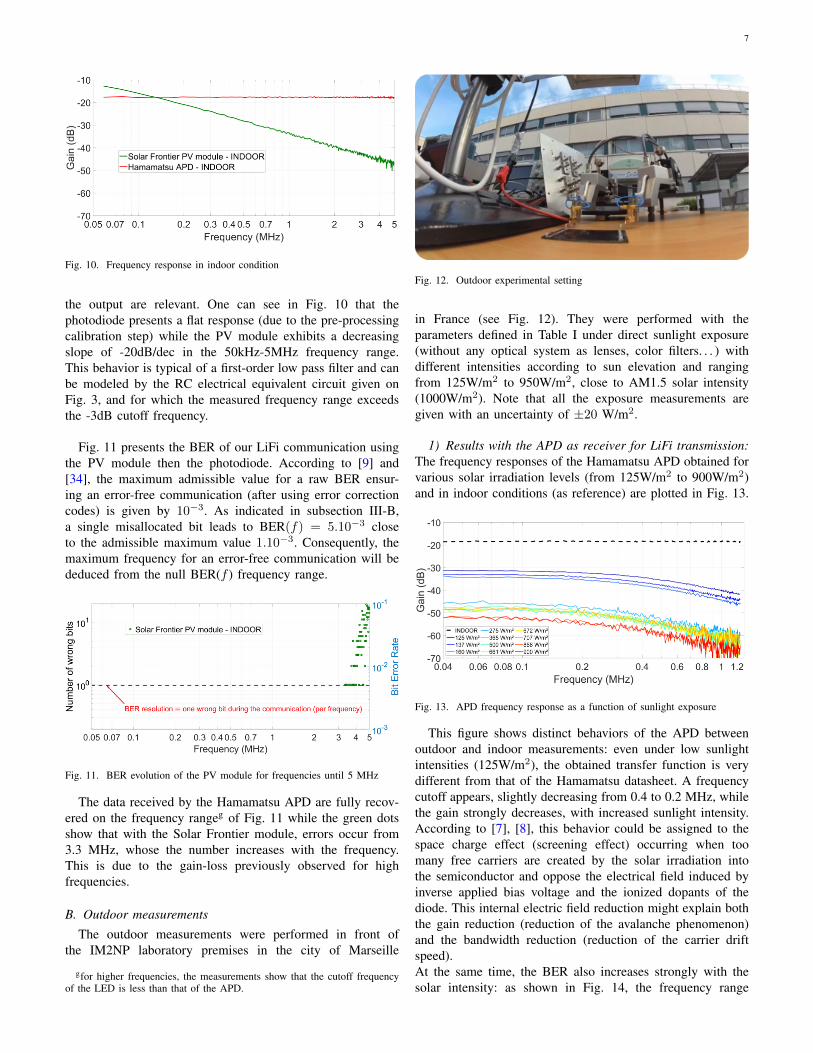
Fig. 11 presents the BER of our LiFi communication usingthe PV module then the photodiode. According to [9] and[34], the maximum admissible value for a raw BER ensur-ing an error-free communication (after using error correctioncodes) is given by 10−3. As indicated in subsection III-B,a single misallocated bit leads to BER(f) = 5.10−3 closeto the admissible maximum value 1.10−3. Consequently, themaximum frequency for an error-free communication will bededuced from the null BER(f ) frequency range.
Fig. 11. BER evolution of the PV module for frequencies until 5 MHz
The data received by the Hamamatsu APD are fully recov-ered on the frequency rangeg of Fig. 11 while the green dotsshow that with the Solar Frontier module, errors occur from3.3 MHz, whose the number increases with the frequency.This is due to the gain-loss previously observed for highfrequencies.
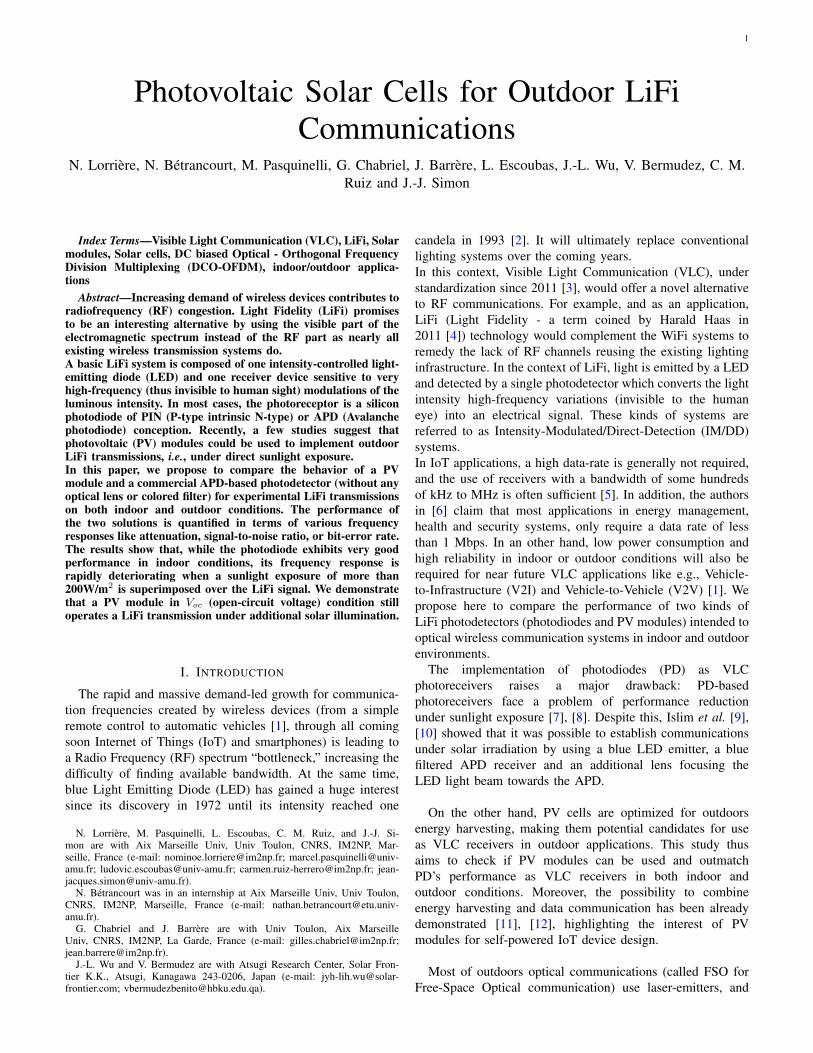
B. Outdoor measurements
The outdoor measurements were performed in front ofthe IM2NP laboratory premises in the city of Marseille
gfor higher frequencies, the measurements show that the cutoff frequencyof the LED is less than that of the APD.
Fig. 12. Outdoor experimental setting
in France (see Fig. 12). They were performed with theparameters defined in Table I under direct sunlight exposure(without any optical system as lenses, color filters. . . ) withdifferent intensities according to sun elevation and rangingfrom 125W/m2 to 950W/m2, close to AM1.5 solar intensity(1000W/m2). Note that all the exposure measurements aregiven with an uncertainty of ±20 W/m2.
1) Results with the APD as receiver for LiFi transmission:The frequency responses of the Hamamatsu APD obtained forvarious solar irradiation levels (from 125W/m2 to 900W/m2)and in indoor conditions (as reference) are plotted in Fig. 13.
Fig. 13. APD frequency response as a function of sunlight exposure
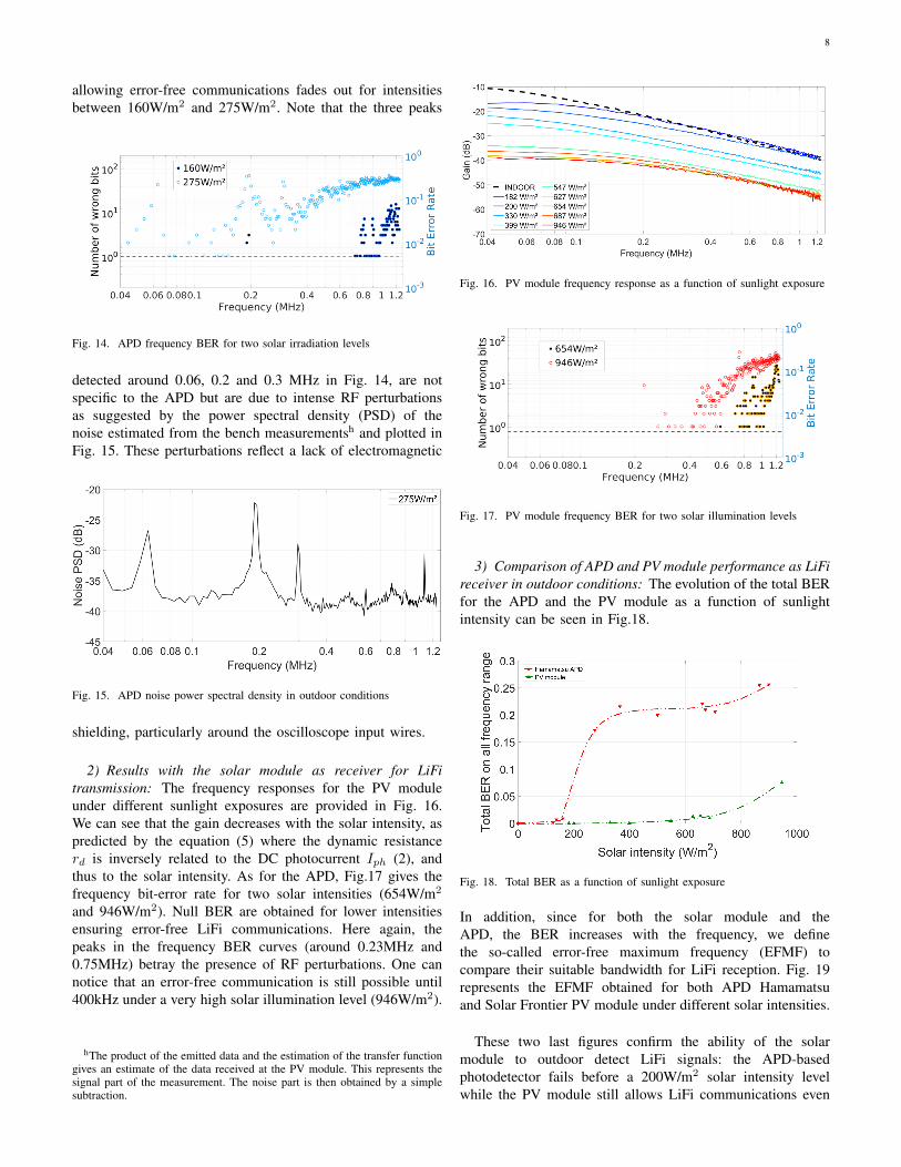
This figure shows distinct behaviors of the APD betweenoutdoor and indoor measurements: even under low sunlightintensities (125W/m2), the obtained transfer function is verydifferent from that of the Hamamatsu datasheet. A frequencycutoff appears, slightly decreasing from 0.4 to 0.2 MHz, whilethe gain strongly decreases, with increased sunlight intensity.According to [7], [8], this behavior could be assigned to thespace charge effect (screening effect) occurring when toomany free carriers are created by the solar irradiation intothe semiconductor and oppose the electrical field induced byinverse applied bias voltage and the ionized dopants of thediode. This internal electric field reduction might explain boththe gain reduction (reduction of the avalanche phenomenon)and the bandwidth reduction (reduction of the carrier driftspeed).At the same time, the BER also increases strongly with thesolar intensity: as shown in Fig. 14, the frequency range
8
allowing error-free communications fades out for intensitiesbetween 160W/m2 and 275W/m2. Note that the three peaks
Fig. 14. APD frequency BER for two solar irradiation levels
detected around 0.06, 0.2 and 0.3 MHz in Fig. 14, are notspecific to the APD but are due to intense RF perturbationsas suggested by the power spectral density (PSD) of thenoise estimated from the bench measurementsh and plotted inFig. 15. These perturbations reflect a lack of electromagnetic
Fig. 15. APD noise power spectral density in outdoor conditions
shielding, particularly around the oscilloscope input wires.
2) Results with the solar module as receiver for LiFitransmission: The frequency responses for the PV moduleunder different sunlight exposures are provided in Fig. 16.We can see that the gain decreases with the solar intensity, aspredicted by the equation (5) where the dynamic resistancerd is inversely related to the DC photocurrent Iph (2), andthus to the solar intensity. As for the APD, Fig.17 gives thefrequency bit-error rate for two solar intensities (654W/m2
and 946W/m2). Null BER are obtained for lower intensitiesensuring error-free LiFi communications. Here again, thepeaks in the frequency BER curves (around 0.23MHz and0.75MHz) betray the presence of RF perturbations. One cannotice that an error-free communication is still possible until400kHz under a very high solar illumination level (946W/m2).
hThe product of the emitted data and the estimation of the transfer functiongives an estimate of the data received at the PV module. This represents thesignal part of the measurement. The noise part is then obtained by a simplesubtraction.
Fig. 16. PV module frequency response as a function of sunlight exposure
Fig. 17. PV module frequency BER for two solar illumination levels
3) Comparison of APD and PV module performance as LiFireceiver in outdoor conditions: The evolution of the total BERfor the APD and the PV module as a function of sunlightintensity can be seen in Fig.18.
Fig. 18. Total BER as a function of sunlight exposure
In addition, since for both the solar module and theAPD, the BER increases with the frequency, we definethe so-called error-free maximum frequency (EFMF) tocompare their suitable bandwidth for LiFi reception. Fig. 19represents the EFMF obtained for both APD Hamamatsuand Solar Frontier PV module under different solar intensities.
These two last figures confirm the ability of the solarmodule to outdoor detect LiFi signals: the APD-basedphotodetector fails before a 200W/m2 solar intensity levelwhile the PV module still allows LiFi communications even

9
Fig. 19. Comparison of the error free maximum frequency between thehamamatsu APD and the solar module
at full sunlight exposure.
V. CONCLUSION AND PERSPECTIVES
By means of an experimental LiFi test bench, we havecompared the behavior of a PV module and a commercialAPD-based photodetector for white LED LiFi transmissionsin both indoor and outdoor conditions. The performance ofthe two solutions has been quantified in terms of frequencyresponses, signal-to-noise ratio and bit-error rate. Finally, theso-called error-free maximum frequency (EFMF) is introducedto quantify the limiting effect of the direct sunlight exposureon data communications. We have shown that the HamamatsuAPD-based photodetector exhibits excellent performance in in-door conditions which decreases significantly when a sunlightexposure of more than 200W/m2 is superimposed over the LiFisignal. This behavior could be explained by a screening effectwhich might be confirmed by additional measurements usingother photodiode-based photodetectors (APD or PIN). On thecontrary, it has been demonstrated for the first time that aPV module in Voc condition still operates a LiFi transmissionuntil around 800W/m2 which corresponds to classic outdoorlighting conditions. This shows that solar panels, as they arecurrently installed in solar farms, can be used as LiFi receivers.In addition, such interesting results can be extended for indoorconditions when direct or indirect sunlight illuminations arenot negligible, as in the case of a system operating near awindow [35].
REFERENCES
[1] D.-R. Kim, S.-H. Yang, H. Kim, Y.-H. Son, and S.-K. Han, “OutdoorVisible Light Communication For Inter-Vehicle Communication UsingController Area Network,” Proceedings of the 2012 Fourth InternationalConferance on Communications and Electronics (ICCE), pp. 31–34,2012.
[2] S. Nakamura, T. Mukai, and M. Senoh, “Candela-class high-brightnessInGaN/AlGaN double-heterostructure blue-light-emitting diodes,” Ap-plied Physics Letters, vol. 64, no. 13, pp. 1687–1689, 1994.
[3] Part 15.7: Short-Range Wireless Optical Communication Using Vis-ible Light, IEEE Standard for Local and Metropolitan Area Net-works, “IEEE Std.802.15.7,” https://standards.ieee.org/standard/802_15_7-2011.html, 2019, accessed: 2019-01-03.
[4] H. Haas, “Wireless data from every light bulb,” TEDGlobal, 2011.
[5] S. Al-Sarawa, M. Anbar, K. Alieyan, and M. Alzubaidi, “Internet ofThings (IoT) Communication Protocols : Review,” Proceedings of the2017 8th IEEE International Conference on Information Technology(ICIT), pp. 685–690, 2017.
[6] T. D. P. Mendes, R. Godina, E. M. G. Rodrigues, J. C. O. Matias,and J. P. S. Catalao, “Smart Home Communication Technologies andApplications: Wireless Protocol Assessment for Home Area,” Energies,vol. 8, no. 7, pp. 7279–7311, 2015.
[7] Hamamatsu Opto-Semiconductor Handbook, https://www.hamamatsu.com/resources/pdf/ssd/e03_handbook_si_apd_mppc.pdf, 2019,accessed: 2020-01-16.
[8] A. Beling, X. Xie, and J. Campbell, “High-power, high-linearity photo-diodes,” Optica, vol. 3, no. 3, pp. 328–338, 2016.
[9] M. Islim and H. Haas, “An Investigation of the Solar Irradiance Effecton Visible Light Communication,” Proceedings of the 2017 IEEE 28thAnnual International Symposium on Personal, Indoor, and Mobile RadioCommunications (PIMRC), pp. 1–6, 2017.
[10] M. Islim, S. Videv, M. Safari, E. Xie, J. McKendry, E. Gu, M. Dawson,and H. Haas, “The Impact of Solar Irradiance on Visible Light Com-munications,” IEEE Journal of Lightwave Technology, vol. 36, no. 12,pp. 2376–2386, 2018.
[11] Z. Wang, D. Tsonev, S. Videv, and H. Haas, “Towards Self-poweredSolar Panel Receiver for Optical Wireless Communication,” Proceedingsof the 2014 IEEE International Conference on Communications (ICC)- Optical Networks and Systems, pp. 3348–3353, 2014.
[12] W.-H. Shin, S.-H. Yang, D.-H. Kwon, and S.-K. Han, “Self-reverse-biased solar panel optical receiver for simultaneous visible light com-munication and energy harvesting,” Optics Express, vol. 24, no. 22, pp.A1300–A1305, 2016.
[13] J. Fakidis, S. Videv, H. Helmers, and H. Haas, “0.5-Gb/s OFDM-BasedLaser Data and Power Transfer Using a GaAs Photovoltaic Cell,” IEEEPhotonics Technology Letters, vol. 30, pp. 841–844, 2018.
[14] J. de Oliveira Filho, A. Trichili, B. Ooi, M. Alouini, and K. Salama,“Towards Self-Powered Internet of Underwater Things Devices,” IEEECommunications Magazine, pp. 1–6, 2019.
[15] S. Das, E. Poves, J. Fakidis, A. Sparks, S. Videv, and H. Haas,“Towards Energy Neutral Wireless Communications: Photovoltaic Cellsto Connect Remote Areas,” Energies, vol. 12, no. 19, pp. 1–19, 2019.
[16] Z. Wang, D. Tsonev, S. Videv, and H. Haas, “On the Design ofa Solar-Panel Receiver for Optical Wireless Communications WithSimultaneous Energy Harvesting,” IEEE Journal on Selected Areas inCommunications, vol. 33, no. 8, pp. 1612–1623, 2015.
[17] E. Bialic, L. Maret, and D. Kténas, “Specific innovative semi-transparentsolar cell for indoor and outdoor LiFi applications,” Applied Optics,vol. 54, no. 27, pp. 8062–8069, 2015.
[18] S.-M. Kim and J.-S. Won, “Simultaneous Reception of Visible LightCommunication and Optical Energy using a Solar Cell Receiver,”Proceedings of the IEEE 2013 International Conference on ICT Con-vergence (ICTC), pp. 896–897, 2013.
[19] K. Sindhubala and B. Vijayalakshmi, “Receiver Intend to Reduce Am-bient Light Noise in Visible-Light Communication using Solar Panels,”Journal of Engineering Science and Technology Review, vol. 10, no. 1,pp. 84–90, 2017.
[20] N. Lorrière, G. Chabriel, J. Barrère, M. Pasquinelli, G. Pic, N. Van-nieuwenhuyse, L. Escoubas, and J.-J. Simon, “LiFi Reception fromOrganic Photovoltaic Modules Subject to Additional DC Illuminationsand Shading Effects,” Proceedings of the 2019 Global LiFi Congress(GLC), pp. 115–119, 2019.
[21] A. Prokes and O. Wilfert, “Analysis and Comparison of Various Free-Space Optical Receiver Configurations,” Proceedings of the SPIE Op-tics/Photonics in Security and Defence, Stockholm, Sweden, vol. 6399,2006.
[22] M. Azadeh, Fiber Optics Engineering, ser. Optical Networks. SpringerUS, 2009.
[23] A. Boudkhil, A. Ouzzani, and B. Soudini, “Analysis of FundamentalPhotodetection Noises and Evaluation of PIN and APD PhotodiodesPerformances using an Optical High Debit Transmission Chain Simu-lated by Optisystem,” International Journal of Computer Applications(0975 –8887), vol. 115, no. 18, pp. 21–29, apr 2015.
[24] A. Heeger and T. Nisbet, “The solar cell - Conditions for optimumperformance,” Solar Energy, vol. 3, no. 1, pp. 12–18, 1959.
[25] T. Mambrini, “Caractérisation de panneaux solaires photovoltaïques enconditions réelles d’implantation et en fonction des différentes technolo-gies,” Ph.D. dissertation, South Paris University - Paris XI, 2014.
[26] H. Rauschenbach, Solar Cell Array Design Handbook. SpringerNetherlands, 1980.

10
[27] D. J. Sandiford, “Temperature dependence of carrier lifetime in silicon,”Proceedings of the Physical Society, vol. 71, no. 6, pp. 1002–1006,jun 1958. [Online]. Available: https://doi.org/10.1088%2F0370-1328%2F71%2F6%2F313
[28] I. Perichaud, “Gettering of impurities in solar silicon,” Solar EnergyMaterials & Solar Cells, vol. 72, pp. 315–326, 2002.
[29] S. Dissanayake and J. Armstrong, “Comparison of ACO-OFDM, DCO-OFDM and ADO-OFDM in IM/DD Systems,” Journal of LightwaveTechnology, vol. 31, no. 7, pp. 1063–1072, 2013.
[30] M. Islim and H. Haas, “Modulation Techniques for Li-Fi,” ZTE Com-munications Special issue on Multi-Gigabit Millimeter-Wave WirelessCommunications, vol. 14, no. 2, pp. 29–40, 2016.
[31] N. Lorrière, E. Bialic, M. Pasquinelli, G. Chabriel, J. Barrère, L. Es-coubas, and J.-J. Simon, “An OFDM Testbed for LiFi PerformanceCharacterization of Photovoltaic Modules,” Proceedings of the 1st IEEEGlobal LiFi Congress (GLC), pp. 1–5, 2018.
[32] Hamamatsu website, “APD C12702 series Datasheet,” https://www.hamamatsu.com/resources/pdf/ssd/c12702series_kacc1214e.pdf,2017, accessed: 2020-01-16.
[33] Standard Tables for Reference Solar Spectral Irradiances: Direct Nor-mal and Hemispherical on 37° Tilted Surface, 2012.
[34] S. Zhang, D. Tsonev, S. Videv, S. Ghosh, G. Turnbull, I. Samuel, andH. Haas, “Organic solar cells as high-speed data detectors for visiblelight communication,” Optica Letter, vol. 2, no. 7, pp. 607–610, 2015.
[35] C. Reynaud, R. Clerc, P. Lechêne, M. Hébert, A. Cazier, and A. Arias,“Evaluation of indoor photovoltaic power production under directionaland diffuse lighting conditions,” Solar Energy Materials and Solar Cells,vol. 200, 2015.