IGLU Graphics and Illustrations Capability Statement (Email)

PHOTOS, ILLUSTRATIONS and GRAPHICS
THREE EUCLID ELEMENTAL CRYSTAL STRUCTURES
Courtesy ‘De Divina Proportione’ Luca Pacioli & Leonardo Da Vinci, 1509
The three Euclidean Elements above represent the Fundamental Crystalline Structures (CL Lattice Structures) which in collaboration with Parameterized Helicoid and Cartenoid Vectors define the Creation Processes of the Universe. With the understanding of these Three CL Structures and Mathematical Modeling with Cartan Geometry along with the understanding of the Dielectric, Electric, Gravitational, and Magnetic Field Tensors interactions; and Quantum Mechanics a Creation Model of the Universe can be derived and explained. The simplicity and beauty of the Creation Model is unique and gives One pause in wondering if the Ancients knew much more than for what we modern humans give them credit. The discussions, derivations, and conclusions presented in the enclosed Addendums provide a unique and fresh alternative approach to the principles of the Einstein, Cartan, Evans Unified Field Theorem (ECE Theory) and other String Theory approaches.
This Paper focuses on the Transient Propagation Waves and relational interactions of the four major Tensor Fields, (Dielectric, Electric, Magnetic, Gravitational), and their effect in the creation of 3D Spatial Content and Counter-Spatial Content (Dielectric Vacuum). Other topics and associated results/ applications and higher Dimensional implications are beyond the scope on this paper.

Photo I Illustration I
PHOTO I Created by passing a Ferro-Cell over the pole of a Neodymium Illustration I Cross Sectional View of the Double Hyper-Trochoid Magnet. By shifting the Ferro-Cell Left-to-Right, Up to Down, or in Compare this View of the Double Hyper-Trochoid image to the any direction; the Phase Shift between FIR (InfraRed) and Figures 3 and 4. (UV) Ultra-Violet, ( the Premises for Mathematical Modeling), is seen. .

PHOTO 2 K. Wheeler
“Between the two Masses (great dark spots) there opens up a ‘gateway’ to Counter-Space (smaller dark spot), into which Space from both sides collapses and the two masses just following; falling is just following without resistance. Counter-Space is an ‘Incommensurable’.” The Bessel function representation of the “Mandelbrot” expansion shows that the limits of the, (y, v or z,) axis in the complex phase plane degenerates as do the quantum mechanics and photon masses. The limit on the (x, u) axis goes to the Incommensurable, (i.e., not having Cartesian coordinates). [5] However, the Incommensurable(Dielectric Vacuum) may possibly be modeled as Crystal Lattices, which this paper assumes.
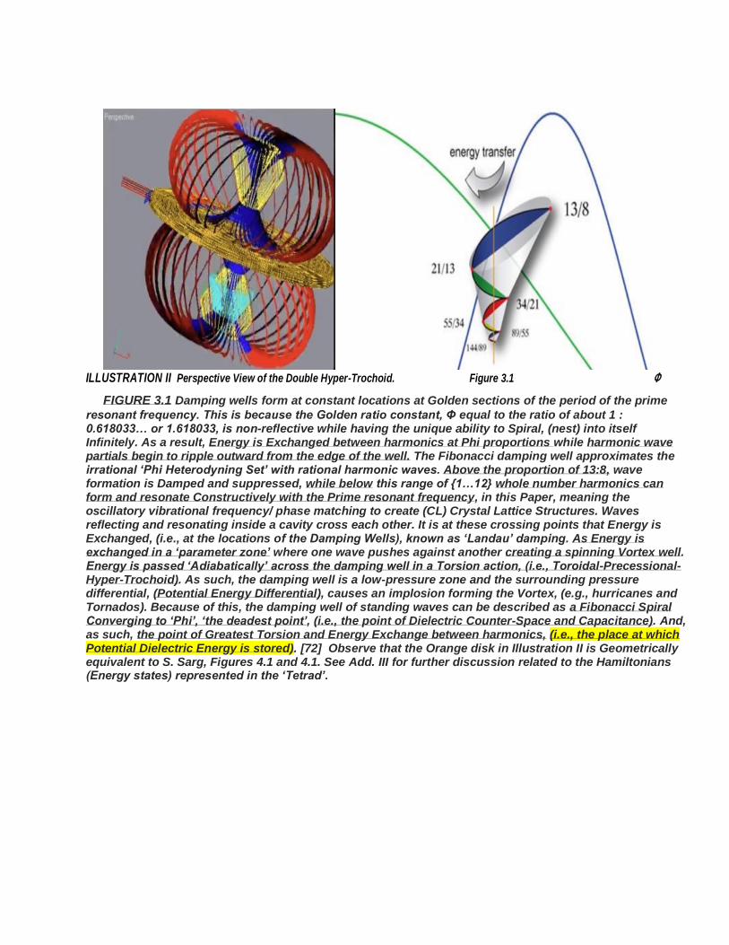
ILLUSTRATION II Perspective View of the Double Hyper-Trochoid. Figure 3.1 Φ
FIGURE 3.1 Damping wells form at constant locations at Golden sections of the period of the prime
resonant frequency. This is because the Golden ratio constant, Φ equal to the ratio of about 1 : 0.618033… or 1.618033, is non-reflective while having the unique ability to Spiral, (nest) into itself Infinitely. As a result, Energy is Exchanged between harmonics at Phi proportions while harmonic wave partials begin to ripple outward from the edge of the well. The Fibonacci damping well approximates the irrational ‘Phi Heterodyning Set’ with rational harmonic waves. Above the proportion of 13:8, wave formation is Damped and suppressed, while below this range of {1…12} whole number harmonics can form and resonate Constructively with the Prime resonant frequency, in this Paper, meaning the oscillatory vibrational frequency/ phase matching to create (CL) Crystal Lattice Structures. Waves reflecting and resonating inside a cavity cross each other. It is at these crossing points that Energy is Exchanged, (i.e., at the locations of the Damping Wells), known as ‘Landau’ damping. As Energy is exchanged in a ‘parameter zone’ where one wave pushes against another creating a spinning Vortex well. Energy is passed ‘Adiabatically’ across the damping well in a Torsion action, (i.e., Toroidal-Precessional-Hyper-Trochoid). As such, the damping well is a low-pressure zone and the surrounding pressure differential, (Potential Energy Differential), causes an implosion forming the Vortex, (e.g., hurricanes and Tornados). Because of this, the damping well of standing waves can be described as a Fibonacci Spiral Converging to ‘Phi’, ‘the deadest point’, (i.e., the point of Dielectric Counter-Space and Capacitance). And, as such, the point of Greatest Torsion and Energy Exchange between harmonics, (i.e., the place at which Potential Dielectric Energy is stored). [72] Observe that the Orange disk in Illustration II is Geometrically equivalent to S. Sarg, Figures 4.1 and 4.1. See Add. III for further discussion related to the Hamiltonians (Energy states) represented in the ‘Tetrad’.

“M ystery creates wonder, and W onder is the basis of man’s Desire to U nderstand .” …Neil Armstrong
ILLUSTRATION III
Left: Illustration of a Spiral Galaxy and the intrinsic properties, Artist rendition of a Magnetic Quasar taken by the Magnetic Field lines, High speed particle jet, and rotations. Chandra Observatory. Courtesy of Pearson Education, Inc. [74] Images from NASA and posted on earthchangesmedia.com [75]
Notice in the illustration at Left the bipolar ejection of high-speed particles and x-rays; and the rotations of the
accretion disk. When viewed from a side view, one sees the Double Torsion Hyper-Trochoid. The Right illustration
shows Bright X-ray jets being expelled from the blackhole at the center of the galaxy. The fast-moving particles
can scatter background light, boosting it into the X-ray band. Alternatively, jerks can generate X-ray emission (or
at least a significant portion of it). The emission turns out to be remarkably uniform everywhere, something that is
extremely unlikely if scattering were responsible, but which is a natural consequence of the magnetic field
process. the energetic particles move at speeds close to the speed of light and extend over hundreds of
thousands of light-years, well beyond the visible boundaries of the galaxy. [73] [75]
“The Basic Laws of the Universe are simple, but because our senses are limited, we can’t grasp them. There is a Pattern in Creation.” “I have deep faith that the Principle of the Universe will be Beautiful and Simple.” …Albert Einstein
Courtesy Space.com [94] Courtesy Darkmatterspace.files.wordpress.com [95]
Artists’ Illustrations Left: High-Speed Jets Spewing out of a Super-Massive Blackhole. Right: Dark Matter Space. “The merger between two black holes produces a single Giant jets of superfast particles spinning supermassive Blackhole. Other mergers between spew from the black hole, the jets." two massive galaxies cause two black holes seen to It could be that a particular breed of produce black of a similar mass to also merge. supermassive galaxies powered by holes at their cores produce such jets. These jets pour outward from the poles of rapidly rotating disks of material orbiting the black hole. The problem is that spiral galaxies are not supposed to have such large jets. Both elliptical and spiral galaxies harbor such black holes, but only J1649+2635 and three others spiral galaxies have been discovered.

Figure 2 Figure 3
Courtesy K. L. Wheeler. [5]
A photographic illustration of the alignment Tensor Fields (Magnetic pointing outward towards the Dielectric center-point). The caption provides an explanation of the Centripetal and Centrifugal forces involved along with the effect of Magnetic precession. Figure 3 provides an illustration and graphical explanation of how the Torsion Forces (i.e., Contorsion Tensors and Torsion Spinors) effectuate the twisting of the Helical and shows how the Magnetic Tensor is creating Spatial CL structures and are centered at and about the Dielectric Inertial Planes. Conversely the Dielectric Tensor Field is creating Counter-space (unobserveable); the Dielectric vacuum creating Counter-spatial Double Tetrahedronal CL structures only observeable as an effect. The illustration as a whole is the Double Hyper-Trochoid structure. These twisting and precessional forces combine to create the Cubic Crystalline structure for Iron and Neodymium, and the Rhombohedron Crystalline structure of Bi III when cooled under ambient conditions. The Trihedral and the Tetrahedron are the base crystalline structures for Bi III, hence
best modeled by the Double Tetrahedron with Edge Length ( 𝟐𝝅
𝟓∗ 𝜱) .

Figure 4: Oscillating Electron (internal lattices not shown). 1 – Electron external Helical structure; 2 – internal Helical structure (i.e., Positron); 3 – Central Core, Rc=3.8866(10-13) m Compton Radius*. Fig. Courtesy of Stoyan Sarg who performed all related verification experiments. [44]-[48]
“The external Helical structure 1 is of prisms (i.e., Cubic Crystal & Double Tetrahedron structures in these analyses), having a twisting (Torsion) that modulates the CL nodes of prisms with the same handedness and appears as a Negative charge (electron). The Core 1 is also from prisms (CL lattices) with twisting (Torsion) creating a negative charge. While the Internal Helical structure 2 is of prisms of opposite handedness creating a positive charge, (i.e., Positrons, Photons).” [45]

Figure 4.1 Model of Micro Scale Characteristics Figure 3.2 Electron confined motion with an Optimal velocity 13.6eV (Case ⒜) and with a velocity Higher than
the optimal one, (Case ⒝) VA- Axial velocity; Vt - Tangential velocity component on a Helical trace;
Vtr- Tangential velocity of rotating electron; VALT- Alternative motion velocity of the internal Helical structure of the Electron (see Fig. 4, Add II); and c - light velocity. Courtesy, S.Sarg, [46]-[49]. SPM-Sarg Phase Matching. FIGURE 3.2 The damping well of standing waves is modeled as a Fibonacci spiral converging to Phi, the deadest location in a standing wave and thus the point of Greatest Torque and Energy Exchange between harmonics. This may be analogue to the “zero line” in ECE Theory. [59] This can be proven by using the Fibonacci series as a nominal solution for the second-order equation known as the ‘characteristic wave damping equation.’ In this proof, the golden ratio Phi becomes the ‘eigenvector’ and the Fibonacci series (1, 1, 2, 3, 5, 8, …} become its ‘Eigenvalues’; Hamiltonians. The harmonic formation is called ‘phi-heterodyning’ where
each harmonic emerges around the Phi eigenvector in nested golden sections like a fractal.
Notice the similarity between the illustration at Left with that of the right-side graphic in Addendum III, Attachment A, Figure 1. This is no coincidence. In Illustration I.1, the ‘H’ represents the Hamiltonian Phase-changes on the Vertical axis, ‘L’ represents the Lagrangian Phase-changes, and the ‘pv’ represents the Phase-changes per unit time on the horizontal axis. This relation is independent of frame reference thereby holding in both Relativistic and Non-Relativistic physics. As such, the Components are vectoral quantities with the applicable direction sign (+/-). (A) ℒ =
𝓅𝓋 − ℋ 𝑎𝑛𝑑 𝑡ℎ𝑒 𝐶𝑙𝑎𝑠𝑠𝑖𝑐𝑎𝑙 𝑟𝑒𝑙𝑎𝑡𝑖𝑜𝑛 𝑖𝑠 𝜕ℒ
𝜕�̇�= 𝓅, 𝑎𝑛𝑑 �̇� = �̇� =
𝓋 . For the ‘H’ Hamiltonian (Energy) and the ‘pv’ term are: ℋ =
[𝑚𝑐2
√(1−𝑣2
𝑐2)] 𝓅𝓋 = [
𝑚𝑣2
√(1−𝑣2
𝑐2)] So, in calculating the Lagrangian,
the Hamiltonian, H, is proportional to γ and the Lagrangian
is proportional to (1/γ) where by: L=-(H-pv)
𝓛 = −[𝒄𝟐−𝒗𝟐
√(𝟏−𝒗𝟐
𝒄𝟐 )] = −[(√(𝟏 − 𝒗𝟐
𝒄𝟐) ∗ 𝒎 ∗ 𝒄𝟐] And, (B) 𝜕ℒ
𝜕�̇�=
𝜕
𝜕𝑣[(−√(1 − 𝑣2
𝑐2) ∗ 𝑚 ∗ 𝑐2] = 𝑚∗𝑣
√(1−𝑣2
𝑐2) = 𝓅

Figure 1 Mathematical model of the Inscribed cubic structure to the dodecahedron, Tensor Fields (B,D,E,G) and their sub-components.
This Model will help to explain the Propagating Wave Functions, the Tensor Field forces, and accelerations. With the model, the ‘tetrad' similar to the Proca ‘tetrad’ will be derived.
The illustration at Left above is not by coincidence; it is the same as the Dirac expressions on Pg. 117, Ref. [25].

Figure 4.1 Model of Micro Scale Characteristics Figure 3.2.1 Illustration of an Avoided Crossing Electron confined motion with an Optimal velocity 13.6eV (Case ⒜) The graph represents the Energy of the system, (Horz. axis),
and with a velocity Higher than the optimal one, (Case ⒝ ) which may vary in time. Dashed lines represent energies of the diabatic
VA- Axial velocity; Vt -Tangential velocity component on a Helical trace; states which cross each other at Zc, and the solid lines represent the Vtr- Tangential velocity of rotating electron; VALT- Alternative motion Energy of the adiabatic states,
velocity of the internal Helical structure of the Electron (i.e., Eigenvalues of the Hamiltonian). See Fig. 3.2 [93] (see Fig. 4, Add II); and c - light velocity. Courtesy, S.Sarg, [46]-[49].
n Axial Velocity
(m/s)
Energy
(eV)
Quantum
Efficiency
1 2.187 (106) 13.6 1 100%
2 1.094 (106) 3.4 ½ 50%
3 7.292 (105) 1.51 (1/3) 33%
4 5.469 (105) 0.85 (1/4) 25%
5 4.375 (105) 0.544 (1/5) 20%
Table 5.1 Courtesy S. Sarg, [44]-[48]

Notice the correlation of the two proposed Gravity Effect Flying generators using Electro-Magneto-Torsion Field and the Figures and illustrations related to the Toroidal-Precessional- Hyper-Trochoids referenced in the above Addendums.


![A Learned Representation for Scalable Vector Graphics · fied with Scalable Vector Graphics (SVG) – a common file format for fonts, human drawings, designs and illustrations [11].](https://static.fdocuments.in/doc/165x107/5fdccc690a10ab2c1e74ae96/a-learned-representation-for-scalable-vector-graphics-ied-with-scalable-vector.jpg)