Photonics
32
Photonics and Optical Communication, Spring 2005, Dr. D. Knipp 1 Waveguides Photonics and Optical Communication (Course Number 300352) Spring 2005 Waveguides Instructor: Dr. Dietmar Knipp http://www.faculty.iu-bremen.de/course/c320352/
-
Upload
berhanubulhca -
Category
Documents
-
view
166 -
download
2
Transcript of Photonics
Photonics and Optical Communication, Spring 2005, Dr. D. Knipp
1Waveguides
Photonics and Optical Communication(Course Number 300352)
Spring 2005
Waveguides
Instructor: Dr. Dietmar Knipp
http://www.faculty.iu-bremen.de/course/c320352/

Photonics and Optical Communication, Spring 2005, Dr. D. Knipp
2Waveguides
Photonics and Optical Communication
3 Waveguides3.1 Introduction 3.2 Reflection and Refraction at the Boundary between two Media3.3 Total internal reflection
3.3.1 Light propagation in an optical fiber3.3.2 Acceptance angle
3.4 Planar Waveguide3.4.1 Planar Mirror Waveguide3.4.2 Planar Dielectric Waveguide
3.5 Modes in Waveguides3.5.1 Transverse Electric Waves3.5.2 Transverse Magnetic Waves 3.5.3 Transverse Electro Magnetic Waves3.5.4 Calculating Modes in a planar wave guide 3.5.5 The effective refractive index3.5.6 The Mode chart3.5.7 Designing a planar wave guide3.5.8 TE versus TM Modes3.5.9 Types of Modes3.5.10 Numbering of modes
Photonics and Optical Communication, Spring 2005, Dr. D. Knipp
3Waveguides
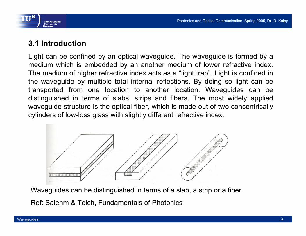
3.1 Introduction Light can be confined by an optical waveguide. The waveguide is formed by a medium which is embedded by an another medium of lower refractive index. The medium of higher refractive index acts as a “light trap”. Light is confined in the waveguide by multiple total internal reflections. By doing so light can be transported from one location to another location. Waveguides can be distinguished in terms of slabs, strips and fibers. The most widely applied waveguide structure is the optical fiber, which is made out of two concentricallycylinders of low-loss glass with slightly different refractive index.
Waveguides can be distinguished in terms of a slab, a strip or a fiber.
Ref: Salehm & Teich, Fundamentals of Photonics
Photonics and Optical Communication, Spring 2005, Dr. D. Knipp
4Waveguides
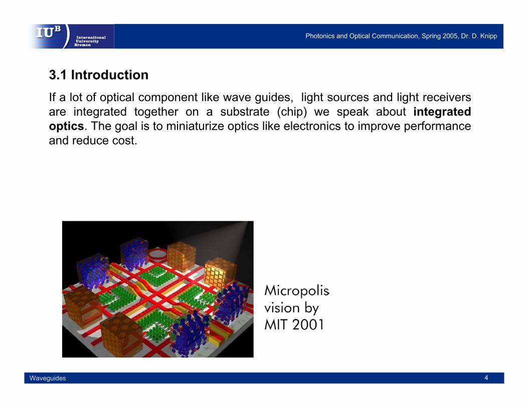
3.1 Introduction If a lot of optical component like wave guides, light sources and light receivers are integrated together on a substrate (chip) we speak about integrated optics. The goal is to miniaturize optics like electronics to improve performance and reduce cost.

Photonics and Optical Communication, Spring 2005, Dr. D. Knipp
5Waveguides
3.1 Introduction The optical fiber in its existing form (the fiber consists of a core and a cladding) was invented 40 years ago. The first fibers were used in the near infrared wavelength region at around 800nm-900nm. As technology of fibers and light sources evolved the optical transmission window was shifted to 1310nm in the mid 1980‘s and 1550nm in the 1990‘s.
Internal reflection is a requirement for the guidance or confinement of waves in a waveguide. Total internal reflection can only be achieved if the refractive index of the core is larger than the refractive index of the cladding. In the following, we will briefly repeat the related ray optics.

Photonics and Optical Communication, Spring 2005, Dr. D. Knipp
6Waveguides
3.2 Reflection and Refraction at the Boundary between two MediaThe reflection and refraction of light at an interface can be described by Snell‘s law. The angle of incidence is given by θ1 which is related to the angle of refraction θ2.
Reflection of rays at an interface. (a) From a high to a low refractive medium, (b) The critical angle, (c) Total internal reflection.
Ref: J.M. Senior, Optical Fiber Communication
2211 sinsin θθ ⋅=⋅ nn
Snell‘s law.

Photonics and Optical Communication, Spring 2005, Dr. D. Knipp
7Waveguides
3.3 Total internal reflectionWith increasing angle of incidence θ1 the angle of refraction θ2 also increases. If n1 > n2, there comes a point when θ2 =π/2 radians. This happens when θ1=sin-1(n2 / n1). For larger values of θ1, there is no refracted ray, and all the energy from the incident ray is reflected. This phenomena is called total internal reflection. The smallest angle for which we get total internal reflection is called the critical angle and θ2 equals π/2 radians.
The total internal reflection is an requirement for the guidance of light in an optical fiber.
1
2sinnn
c =θ Critical angle
Photonics and Optical Communication, Spring 2005, Dr. D. Knipp
8Waveguides
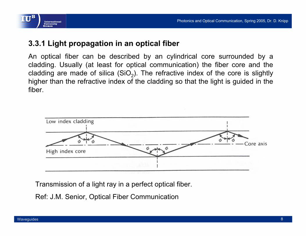
3.3.1 Light propagation in an optical fiberAn optical fiber can be described by an cylindrical core surrounded by a cladding. Usually (at least for optical communication) the fiber core and the cladding are made of silica (SiO2). The refractive index of the core is slightly higher than the refractive index of the cladding so that the light is guided in the fiber.
Transmission of a light ray in a perfect optical fiber.
Ref: J.M. Senior, Optical Fiber Communication

Photonics and Optical Communication, Spring 2005, Dr. D. Knipp
9Waveguides
3.3.2 Acceptance angleTotal internal reflection is required to guide light in an optical fiber. We know that only light under sufficient shallow angles (angle greater than the critical angle) can propagate in the fiber. The question is now under what angle a ray can enter a fiber? It is clear that not all rays entering the fiber core will continue to be propagated along the fiber. Only rays that enter the fiber within a acceptance cone (acceptance angle) will propagate along the fiber, whereas rays outside of the cone will not be guided.
Coupling of a ray into a fiber. The ray can only be coupled into the fiber when the angle of incident is within the acceptance cone.
Ref: J.M. Senior, Optical Fiber Communication
Photonics and Optical Communication, Spring 2005, Dr. D. Knipp
10Waveguides
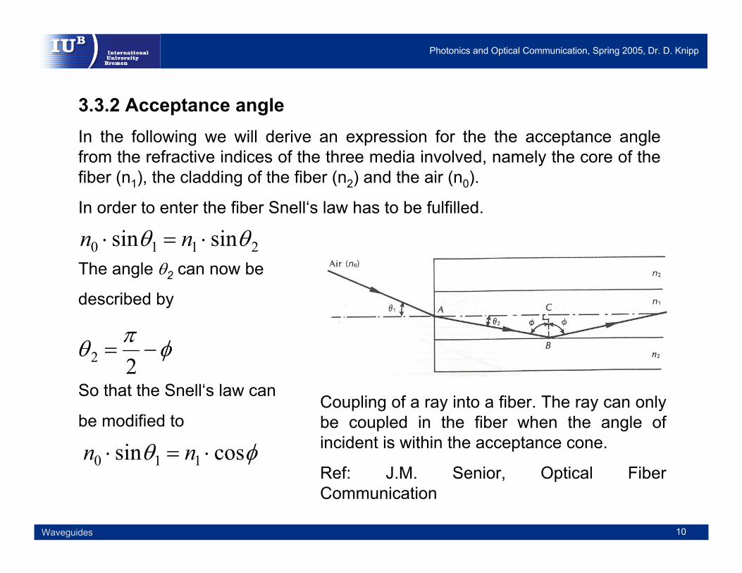
3.3.2 Acceptance angleIn the following we will derive an expression for the the acceptance angle from the refractive indices of the three media involved, namely the core of the fiber (n1), the cladding of the fiber (n2) and the air (n0).
In order to enter the fiber Snell‘s law has to be fulfilled.
The angle θ2 can now be
described by
So that the Snell‘s law can
be modified to
2110 sinsin θθ ⋅=⋅ nn
φπθ −=22
φθ cossin 110 ⋅=⋅ nn
Coupling of a ray into a fiber. The ray can only be coupled in the fiber when the angle of incident is within the acceptance cone.
Ref: J.M. Senior, Optical Fiber Communication

Photonics and Optical Communication, Spring 2005, Dr. D. Knipp
11Waveguides
3.3.2 Acceptance angleIf we consider now the trigonometrically relationship
The expression can be modified to
Now the equation can be combined with the equation for the critical angle
Leading to the relationship for the numerical aperture
The acceptance angle can now be calculated by
( ) ( ) 1cossin 22 =+ φφ
φθ 2110 sin1sin −=⋅ nn
( )121sin nn−=φ
22
2110 sin nnnNA −=⋅= θ Numerical aperture
Acceptance angle
−=< −
0
22
211
1 sinnnn
a θθ

Photonics and Optical Communication, Spring 2005, Dr. D. Knipp
12Waveguides
3.4 Planar waveguideThe planar waveguide is the simplest form of an optical waveguide. The waveguide can be realized by a simple sandwich structure which consists of a slab embedded between two mirrors or a two regions of lower refractive index. Depending on the waveguide structure it can be distinguished between planar mirror waveguides, where the core of the waveguide is embedded between two mirrors and planar dielectric waveguides, where the core of the waveguide is embedded between regions of lower refractive index.
Types of waveguides:
- Mirror waveguides
- Dielectric Waveguides
Choosing different claddings of the waveguide has an important influence on the propagation of waves in the waveguide.

Photonics and Optical Communication, Spring 2005, Dr. D. Knipp
13Waveguides
3.4.1 Planar Mirror waveguideA planar mirror waveguide is shown on this slide. The cladding of the waveguide is formed by a conducting material, which can be a mirror.
As a consequence of the conducting cladding the tangential components of the electric and the magnetic field is zero at the interface between the core and the cladding.
Therefore, the waves can not extend in the cladding of the waveguide. Subsequently the modes of propagation are given defined by the dimensions of the core of the waveguide.
Cross section of a mirror waveguide
Ref: Back to Basics in Optical Communications, Tutorial Agilent Technologies
0=TE 0=TB
Photonics and Optical Communication, Spring 2005, Dr. D. Knipp
14Waveguides
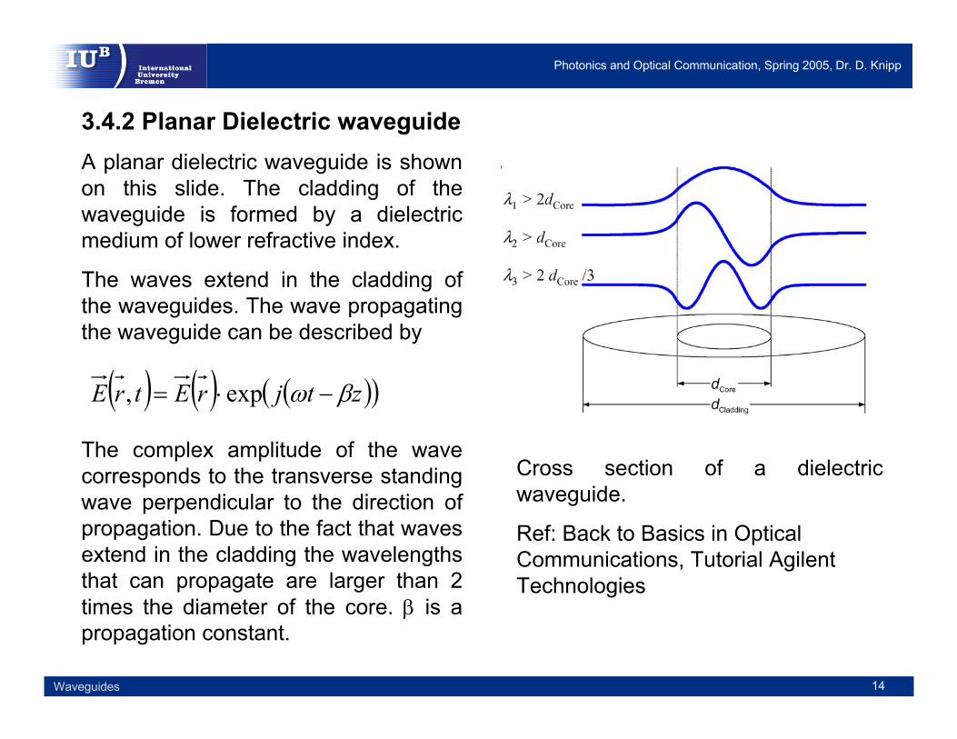
3.4.2 Planar Dielectric waveguideA planar dielectric waveguide is shown on this slide. The cladding of the waveguide is formed by a dielectric medium of lower refractive index.
The waves extend in the cladding of the waveguides. The wave propagating the waveguide can be described by
The complex amplitude of the wave corresponds to the transverse standing wave perpendicular to the direction of propagation. Due to the fact that waves extend in the cladding the wavelengths that can propagate are larger than 2 times the diameter of the core. β is a propagation constant.
Cross section of a dielectric waveguide.
Ref: Back to Basics in Optical Communications, Tutorial AgilentTechnologies
( ) ( ) ( )( )ztjrEtrE βω −⋅= exp,

Photonics and Optical Communication, Spring 2005, Dr. D. Knipp
15Waveguides
3.5 Modes in WaveguidesThe planar waveguide is the simplest form of an optical waveguide. The waveguide can be realized by a simple sandwich structure which consists of a slab embedded between two regions of lower refractive index.
The optical ray within the waveguide can be described by a transverse electromagnetic wave, which can be a TE, TM or TEM wave.
Propagation of a wave in a planar waveguide. We can impose self-consistency condition which requires that the wave reproduces itself. Fields that satisfy this conditions are called Eigenmodes(modes) of the waveguide.
Ref: Saleh and Teich,Fundamentals of Photonics
Photonics and Optical Communication, Spring 2005, Dr. D. Knipp
16Waveguides
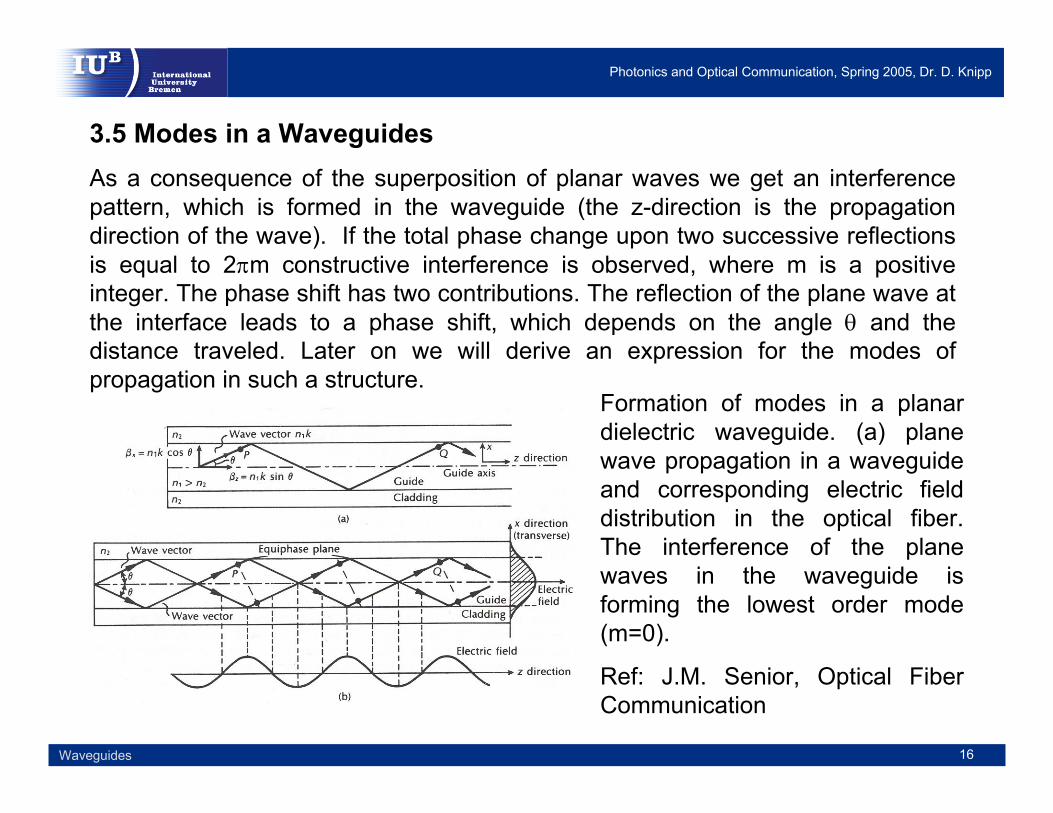
3.5 Modes in a WaveguidesAs a consequence of the superposition of planar waves we get an interference pattern, which is formed in the waveguide (the z-direction is the propagation direction of the wave). If the total phase change upon two successive reflections is equal to 2πm constructive interference is observed, where m is a positive integer. The phase shift has two contributions. The reflection of the plane wave at the interface leads to a phase shift, which depends on the angle θ and the distance traveled. Later on we will derive an expression for the modes of propagation in such a structure.
Formation of modes in a planardielectric waveguide. (a) planewave propagation in a waveguideand corresponding electric field distribution in the optical fiber. The interference of the planewaves in the waveguide is forming the lowest order mode (m=0).
Ref: J.M. Senior, Optical Fiber Communication
Photonics and Optical Communication, Spring 2005, Dr. D. Knipp
17Waveguides
3.5 Modes in a WaveguidesIn the figure on the previous slide the lowest order mode (m=0) is shown. A mode of propagation is only observed when the angle between the propagation vector and the interface (boundary of the cladding and the core) has particular values. For all modes of propagation a standing wave is formed in the waveguide. Depending on the mode of propagation an electric field distribution is formed. For the lowest order mode the electric field is maximized in the center of the core. The electric field decays towards the boundaries. For all modes of propagation the self-consistency condition has to be satisfied which means that the wave in the waveguide reproducing itself.
Before discussing the modes of propagation mathematically we will discuss the propagation of waves in a waveguide phenomenologically .

Photonics and Optical Communication, Spring 2005, Dr. D. Knipp
18Waveguides
3.5 Modes in WaveguidesAgain we assume a plane wave which propagates in the z-direction. We observe constructive interference across the waveguide as a consequence of the superposition of the propagating waves. In the examples shown on this slide the propagation modes are m=1, 2 and 3. The number of modes corresponds to the number of zeros in the transverse electric field pattern.
How do we determine the self-consistency conditions. In order to achieve total internal reflection the angle of incidence has to be smaller than
Propagation of waves in a waveguideand the corresponding transverse electric (TE) field pattern of three lower order models m=1, 2, 3.
Ref: J.M. Senior, Optical Fiber Communication
=
−< −−
1
21
1
21 cossin2 n
nnn
Cπθ

Photonics and Optical Communication, Spring 2005, Dr. D. Knipp
19Waveguides
For self-consistency the wave reproduces itself and the phase shift between the two waves has to be zero or a multiple of 2π.
We can assume that the field in the slab is in the form of a monochromatic plane wave bouncing back and forth at an angle θ smaller than the critical angle θC. A round trip can be described by:
For self-consistency the phase shift between the two waves has to be zero or a multiple of 2π.
Planar dielectric waveguide.
Ref: Saleh and Teich, Fundamentals of Photonics
3.5 Modes in Waveguides
θsin2dABAC =−
Photonics and Optical Communication, Spring 2005, Dr. D. Knipp
20Waveguides
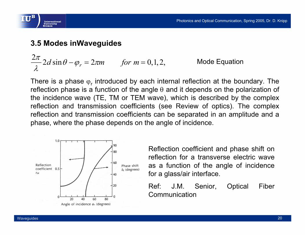
3.5 Modes inWaveguides
There is a phase ϕr introduced by each internal reflection at the boundary. The reflection phase is a function of the angle θ and it depends on the polarization of the incidence wave (TE, TM or TEM wave), which is described by the complex reflection and transmission coefficients (see Review of optics). The complex reflection and transmission coefficients can be separated in an amplitude and a phase, where the phase depends on the angle of incidence.
,2,1,02sin22==− mformd r πϕθ
λπ Mode Equation
Reflection coefficient and phase shift on reflection for a transverse electric wave as a function of the angle of incidence for a glass/air interface.
Ref: J.M. Senior, Optical Fiber Communication

Photonics and Optical Communication, Spring 2005, Dr. D. Knipp
21Waveguides
3.5.1 Transverse Electric WavesIn the case of a transverse electric field (TE mode) the electric field is perpendicular to the direction of propagation of the wave (z-direction). As we are dealing with electro-magnetic waves each wave consists of a periodically varying electric and magnetic field which is again perpendicular to each other. In the case of a TE transverse wave the electric is perpendicular to the direction of propagation (Ez=0) and the magnetic field has a (small) component to the direction of propagation. This is due to the fact that the traveling wave is not propagating in a straight line in the wave guide, meaning the ray is propagation on a zigzag path.
Propagation of a TE wave in a slab waveguide.
Ref: J.C. Palais, Fiber Optic Communication
z
x
B
Photonics and Optical Communication, Spring 2005, Dr. D. Knipp
22Waveguides
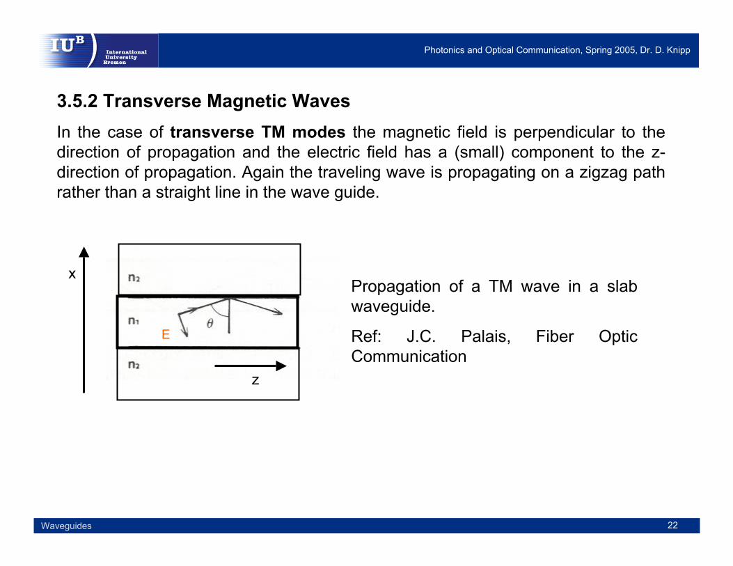
3.5.2 Transverse Magnetic WavesIn the case of transverse TM modes the magnetic field is perpendicular to the direction of propagation and the electric field has a (small) component to the z-direction of propagation. Again the traveling wave is propagating on a zigzag path rather than a straight line in the wave guide.
Propagation of a TM wave in a slab waveguide.
Ref: J.C. Palais, Fiber Optic Communication
z
x
E

Photonics and Optical Communication, Spring 2005, Dr. D. Knipp
23Waveguides
3.5.3 Transverse Electro Magnetic WavesIn the case of a TEM transverse wave (TEM modes) both the electric and the magnetic field are perpendicular to the direction of propagation, which means that the rays propagate straight in the fiber. Such cases occurs only for single mode fibers.
3.5.4 Calculating Modes in a planar wave guideThe mode equation and the equation for the phase shift have to be merged, which leads to a transcendental equation. The transcendental equation has to be solved to get the modes which propagate in a given waveguide structure. A detailed mathematical description is given by Saleh and Teich in their bookFundamentals of Photonics.

Photonics and Optical Communication, Spring 2005, Dr. D. Knipp
24Waveguides
3.5.5 The effective refractive indexThe effective refractive index is defined by:
The effective refractive index is a key parameter for waveguides like the refractive index is a key parameter for the free space propagation of waves. The effective refractive index changes the wavelength in the same way that a bulk refractive index does. The idea of the effective refractive index gets clear by simply looking at the structure of a waveguide. The effective refractive index is a corrected refractive index which simply assumes that the wave propagates in a straight line the media (in our case in the core of the waveguide structure.)
θsin1nneff =
Plane wave propagating in a waveguide. The effective refractive index considers that the plane wave propagates by following a zigzag path.
Ref: J.C. Palais, Fiber Optic Communicationz
x

Photonics and Optical Communication, Spring 2005, Dr. D. Knipp
25Waveguides
3.5.6 The Mode chartThe mode chart for a waveguide structure is an absolutely essential graph to study the propagation of modes in a given waveguide structure. The thickness/diameter (d) of the core of the waveguide is usually normalized by the wavelength of the incident light. The different modes of propagation are plotted for the propagation angle and the effective refractive index.
Mode chart for a symmetric slab. The following refractive indices were assumed for the core n1=3.6 and the cladding n2=3.55 (AlGaAsstructure).
Ref: J.C. Palais, Fiber Optic Communication

Photonics and Optical Communication, Spring 2005, Dr. D. Knipp
26Waveguides
3.5.6 The Mode chartFor the particular mode chart shown on the previous slide an AlGaAs waveguidestructure (used for a laser diode) is assumed The critical angle for the structure
is
Therefore, the range of angles for which the ray is trapped in the waveguide is then 80.4° – 90°. As a consequence the effective refractive index ranges from 3.55 to 3.6.
From the mode chart we can draw the following conclusions:
When the core thickness is very small in comparison to the wavelength of the propagating light the wave travels very close to the critical angle and the effective index is close to the refractive index of the refractive index of the cladding. The wave penetrates deeply into the outer layers, because the rays are near the critical angle.
With increasing thickness of the core the ray travels at larger angles. The ray travels more parallel to the waveguide axis. For thick films (thickness is large in comparison with the wavelength of the propagating light) the effective index is very close to the refractive index of the film itself.
( ) °== − 4.80sin 121 nncθ

Photonics and Optical Communication, Spring 2005, Dr. D. Knipp
27Waveguides
3.5.7 Designing a planar wave guideFor any given propagation angle there is a set of film thicknesses that will allow rays to propagate. The following equation has to be satisfied for the higher modes, where m is a positive integer.
In order to change the mode the normalized thickness has to change by:
θλλ cos2 10 nmdd
m+
=
( )θ
λcos21
1nd =∆
Table of TEm modes in a gallium arsenide waveguide.
Ref: J.C. Palais, Fiber Optic Communication

Photonics and Optical Communication, Spring 2005, Dr. D. Knipp
28Waveguides
3.5.7 Designing a planar wave guideThe following equation can be applied to calculate the number of TE modes supported by the dielectric waveguide, where m is increased to the nearest integer.
3.5.8 TE versus TM ModesSo far we discussed only the propagation of TE modes. However, TM modesexhibit almost identical propagation behavior. This is why we will not distinguish between TM and TE modes. Therefore, the curve in the mode chart were labeled as both TE and TM modes. This is mostly true since the difference in the refractive index for the core and the cladding are very small (in the range of a few percent). Even with increasing difference the cutoff modes are identical. For each TE mode there will be always a TM mode. The number of total modes is therefore twice the number of TE modes. The electric field distribution for the different mode is shown in the following.
( )21
22
21
02
nnNA
NAdm
−=
=λ
Number of TE Modes
Numerical Aperture

Photonics and Optical Communication, Spring 2005, Dr. D. Knipp
29Waveguides
3.5.9 Types of ModesIn the case of a transverse TE (TE modes) wave the electric field is perpendicular to the direction of propagation and the magnetic field has a (small) component that is in the direction of the propagation.
In the case of a transverse TM (TM modes) wave the magnetic field is perpendicular to the direction of propagation and the electric field has a (small) component that is in the direction of the propagation.
In the case of a TEM transverse wave (TEM modes) both the electric and the magnetic field are perpendicular to the direction of propagation, which means that the rays propagate straight in the fiber. Such cases occurs only for single mode fibers.
Furthermore, helical modes (HE or EH) modes exist. Under such conditions the ray travels in a circular path in the fiber and electric and magnetic field have components in the z-direction. These modes can be realized either as a HE or a EH mode depending on which field contributes most to the z-direction.

Photonics and Optical Communication, Spring 2005, Dr. D. Knipp
30Waveguides
3.5.10 Numbering of ModesIt turns out that the difference in refractive index between the cladding and the core is usually very small. The modes for TE, TM, HE and EH modes are very similar. Therefore, we can simplify the way we look at modes in waveguides and fibers. The listed modes can be summarized and explained using only a single set of LP (linear polarized) modes.
The TE and the TM modes were numbered based on the number of zeros in their electric field pattern across the waveguide. Therefore a TE0 mode would be a continuous distribution with only a single maxima but no zeros. A TE00 mode would be a mode for a 2-dimensional waveguide structure and the electric field distribution would correspond to a single spot. Obliviously a waveguide structure does not have to be symmetric. A TE21 would be now a pattern with 2 zeros in one direction and a third zero in the perpendicular direction.
Electric field distribution for some symmetric and asymmetric slab waveguides. The numbering for TE, TM and TEM mode is identical.
Ref: H. Dutton, Understanding Optical Communication

Photonics and Optical Communication, Spring 2005, Dr. D. Knipp
31Waveguides
3.5.10 Numbering of modesNumbering of linear polarized modes is different from numbering TE and TM modes, but LP numbers are only used for fibers (circular waveguides). LP modes are described by LPlm where m is the number of maxima along the radius of the fiber and l is half of the number of maxima around the circumference.
Correspondence between the linear polarized modes and the traditional exact modes in a cylindrical fiber.
Ref: J.M. Senior, Optical Fiber Communication
Photonics and Optical Communication, Spring 2005, Dr. D. Knipp
32Waveguides
References:Stamatios V. Kartalopoulos, DWDM, Networks, Devices and Technology, IEEE press and Wiley Interscience, 2003.
Eugene Hecht, Optics, Addison Wesly, 4th edition, 2002
Fawwalz T. Ulaby, Fundamentals of Applied Electromagnetics, Prentice Hall, 2001.
John M. Senior, Optical Fiber Communications, Prentice Hall Series in Optoelectonics, 2nd edition, 1992.
Bahaa E.A. Saleh, Malvin Carl Teich, Fundamentals of Photonics,Wiley-Interscience (1991)
Harry J. R. Dutton, Understanding Optical Communications, Prentice Hall Series in Networking, 1998. (Formerly freely available as a red book on the IBM red book server.
Joseph C. Palais, Fiber Optic Communications, Prentice Hall Series, 1998. 4th edition.