
photonics-01-00198
13
Photonics 2014, 1, 198-210; doi:10.3390/photonics1030198 OPEN ACCESS photonics ISSN 2304-6732 www.mdpi.com/journal/photonics Article FTTA System Demo Using Optical Fiber-Coupled Active Antennas Niels Neumann *, Robert Trieb, Stephan Frach and Dirk Plettemeier Chair for RF Engineering, TU Dresden, 01062 Dresden, Germany; E-Mails: [email protected] (R.T.); [email protected] (S.F.); [email protected] (D.P.) * Author to whom correspondence should be addressed; E-Mail: [email protected]. Received: 1 July 2014; in revised form: 24 July 2014 / Accepted: 29 July 2014 / Published: 5 August 2014 Abstract: The convergence of optical and wireless systems such as Radio-over-Fiber (RoF) networks is the key to coping with the increasing bandwidth demands due to the increasing popularity of video and other high data rate applications. A high level of integration of optical technologies enables simple base stations with a fiber-to-the-antenna (FTTA) approach. In this paper, we present a complete full-duplex RoF–FTTA system consisting of integrated active fiber-coupled optical receiving and transmitting antennas that are directly connected to a standard single mode fiber optical link. Data rates up to 1 Gbit/s could be shown without advanced modulation formats on a 1.5 GHz carrier frequency. The antennas as well as the whole system are explained and the results of the system experiments are discussed. Keywords: antennas; Radio-over-Fiber; active antennas; wireless RF components and systems; microwave photonics 1. Introduction Photonic technologies provide high bandwidths and low attenuation. Hence, they are of high interest for the distribution of wireless data using advanced Radio-over-Fiber (RoF) networks with remote central stations and cost-effective antenna sites [1,2]. The highest level of convergence can be achieved by Fiber-to-the-Antenna (FTTA) setups. FTTA systems consist of fiber-coupled Rx and Tx antennas and a fiber network connecting the antennas with the central station (CS) of the RoF system.
-
Upload
art-andrews -
Category
Documents
-
view
212 -
download
0
description
Fiber Optic manual
Transcript of photonics-01-00198
Photonics 2014, 1, 198-210; doi:10.3390/photonics1030198OPEN ACCESS
photonicsISSN 2304-6732
www.mdpi.com/journal/photonics
Article
FTTA System Demo Using Optical Fiber-CoupledActive AntennasNiels Neumann *, Robert Trieb, Stephan Frach and Dirk Plettemeier
Chair for RF Engineering, TU Dresden, 01062 Dresden, Germany;E-Mails: [email protected] (R.T.); [email protected] (S.F.);[email protected] (D.P.)
* Author to whom correspondence should be addressed; E-Mail: [email protected].
Received: 1 July 2014; in revised form: 24 July 2014 / Accepted: 29 July 2014 /Published: 5 August 2014
Abstract: The convergence of optical and wireless systems such as Radio-over-Fiber (RoF)networks is the key to coping with the increasing bandwidth demands due to the increasingpopularity of video and other high data rate applications. A high level of integration of opticaltechnologies enables simple base stations with a fiber-to-the-antenna (FTTA) approach.In this paper, we present a complete full-duplex RoF–FTTA system consisting of integratedactive fiber-coupled optical receiving and transmitting antennas that are directly connectedto a standard single mode fiber optical link. Data rates up to 1 Gbit/s could be shown withoutadvanced modulation formats on a 1.5 GHz carrier frequency. The antennas as well as thewhole system are explained and the results of the system experiments are discussed.
Keywords: antennas; Radio-over-Fiber; active antennas; wireless RF components andsystems; microwave photonics
1. Introduction
Photonic technologies provide high bandwidths and low attenuation. Hence, they are of high interestfor the distribution of wireless data using advanced Radio-over-Fiber (RoF) networks with remote centralstations and cost-effective antenna sites [1,2]. The highest level of convergence can be achieved byFiber-to-the-Antenna (FTTA) setups. FTTA systems consist of fiber-coupled Rx and Tx antennas and afiber network connecting the antennas with the central station (CS) of the RoF system.

Photonics 2014, 1 199
Integrated fiber-coupled single-element Tx antennas have been proposed with the optoelectronicconversion (photodiode with fiber pigtail) located at the feeding point of the antenna [3]. Comparedwith a single element solution, the beam pattern can be adjusted and more degrees of freedom for thedesign are obtained using antenna arrays. In phased array systems, photonic beamforming networksexhibiting true time delay (TTD) techniques have been used [4,5]. These antenna systems employedelectrical feeding lines to the radiating elements [6] that suffered from losses and other imperfections.
The authors previously demonstrated a lightweight and broadband transmitting antenna withcombined photonic feeding and beamforming [7,8]. Fiber-coupled photodiodes were located directlyat the feeding point of the antenna elements of the array. The beamforming network was realized byoptical fibers. This meant that the RoF central station may be located up to several kilometers away fromthe antenna site.
The weak received radio signal of Rx antennas needs to modulate an optical carrier.Electro-absorption modulators have been used [9,10]. This approach implied the use of an external lasersource. Additionally, realizing advanced antenna structures that provide more gain, higher bandwidths,etc. is challenging with that approach. A highly integrated solution comprising a VCSEL and a patchantenna was presented in [11]. However, multimode VCSELs have a different emission wavelength andare not suitable for standard single mode fiber networks.
The authors also presented an active fiber-coupled antenna in which the complete circuitry to convertthe received radio signal to the optical domain was integrated on the antenna [12]. A fiber-coupledlaser diode as well as its driver and preamplifiers were integrated onto the Vivaldi antenna PCB. A highrelative bandwidth of 133% could be reached. It has been shown (e.g., for UWB applications [13]) thatthe existing antenna dispersion of Vivaldi antennas used in our Rx and Tx antennas can be neglected.Thus, one does not expect to see effects due to antenna dispersion.
In [14], a UWB over Fiber system was realized. However, there was no back channel fromthe remote site to the central station, i.e., only a fiber-coupled remote Tx antenna was realized.Moreover, a commercial Tx antenna was used, and was therefore not integrated with the optical receiver.Lee et al. [15] also demonstrated only downlink functionality with a fiber-coupled remote Tx antenna.FTTA systems with integrated Rx and Tx antennas have been shown in the context of high carrierfrequencies where even short electrical waveguides cannot be used [16]. Few full-duplex systems havebeen built with horn antennas where the optical receiver is externally connected [17]. A completesystem is proposed in [18] but was only measured without wireless link (i.e., without antennas).In [19], a wireless link was included but due to only MHz bandwidth just IEEE 802.11 Wireless LANwas supported.
We demonstrate a complete full-duplex FTTA system with integrated fiber-coupled Rx and Txantennas. Also, a central station providing RF upconversion and downconversion was added in this paper.Using the previously introduced antennas and optical feeding network [7,8,12], a complete system setupis assembled that is capable of broadband multi-standard transparent transmission. The antennas aredirectly connected to a standard single mode fiber network. The frequency range of the antennas includesGSM, UMTS, LTE and WiFi frequencies. Due to the broadband system design (500 MHz to 2.5 GHz),a variety of existing standards is supported by the low-cost PCB antennas. Metro network transmissiondistances (i.e., tens of kilometers) between the Central Station (CS) and the fiber-coupled antennas are

Photonics 2014, 1 200
experimentally researched. Consequently, a complete RoF link from the central station to the basestation, a wireless transmission and the transmission from the base station back to the central stationis investigated.
At first, the developed components and the system setup are summarized. In the second part, theexperimental FTTA system demonstration results are discussed.
2. Components and Setup
A FTTA system for wireless applications consists of different building blocks. In the CS, thesophisticated equipment (e.g., RF components, electronic equalization and signal processing, etc.) isconcentrated. The potentially high number of Base Stations (BS) should be simple and cost-effective.Therefore, antennas with integrated optical interfaces have been proposed and are discussed in detailin Sections 2.1 and 2.2. The wireless signals are transported transparently over the fiber, so that thecompatibility to existing Mobile Stations (MS) is ensured. Figure 1 summarizes the general setup ofsuch an RoF–FTTA system.
Figure 1. RoF–FTTA system overview: Central Station (CS), Optical Fiber Network, BaseStation (BS) with fiber-coupled Rx antenna and Mobile Station (MS).
CS
MS
BS
Optical Network
Tx antenna
Rx antenna
Tx
Rx
In the CS, the wireless signal is generated, i.e., the data is modulated on an electrical carrier accordingto the wireless standard. This signal is amplified and modulated on an optical carrier for transport overexisting fiber infrastructure. Usually, a DFB laser diode serves as optical source due to its superiorcost and performance features. This RF-over-Fiber scheme ensures the most simple BS configurationproviding an RoF signal. The CS also converts the received RoF signal back to electrical domain usinga photodiode and demodulates the electrical signal to retrieve and further process the data.
A full-duplex operation of the BS is provided by separate Rx and Tx antennas. The Tx antennareceives the optical downlink data from the CS and converts it to the electrical domain using a photodiodelocated at the feeding point of the antenna. The Rx antenna receives the wireless signal from the MS.It is amplified and modulated on an optical carrier (DFB laser diode) onboard the antenna PCB for uplinktransmission to the CS. The single mode fiber (SMF) network has a flat frequency response due to itsbroadband behavior. For transmission distances within tens of kilometers, chromatic dispersion is not anissue. The typical attenuation of a SMF is 0.2 dB/km.

Photonics 2014, 1 201
2.1. Tx Antenna
After transmitting the RoF signal generated in the CS over an existing SMF link, the modulated RFsignal has to be converted back to the electrical domain and fed to an antenna for wireless radiation.Photodiodes convert the incoming RoF signal from the optical domain to the electrical domain. Antennaarrays may provide beamforming, beam steering and beam switching. By using an optical beamformingnetwork true time delay (TTD) is provided. A minimum of electronics and RF wiring can be achievedat the BS by placing the photodiode directly on the feeding point of the antenna. We demonstrated suchTx antenna arrays in [7,8]. The direct connection of the photodiode to the feeding point of the antennalimits the transmission power of the antenna to the output power of the photodiode, i.e., a few milliwatts.Consequently, the transmission distances will be restricted. The authors decided to nevertheless followthis path for the subsequent reasons: (1) Mounting the photodiode at the feeding point of the antenna isthe highest possible degree of integration. This was one of the research goals of the authors that requireda different design than traditionally fed active antennas with power amplifiers as last stage (e.g., [20]);(2) FTTA configurations with highly reduced amount of electronics are especially of interest for indoorapplications where a high number of simple Tx stations are needed. In this scenario, only low powers areneeded and the few mWprovided by only the photodiode is sufficient; (3) For measurement purposes,lower powers are easier to handle in the (unshielded) lab because the risk of jamming commercialservices within the frequency range of the antenna is reduced.
Here, a 2 × 1 Tx antenna array configuration is used. The antenna is shown in Figure 2 and thecorresponding photonic beamforming network is depicted in Figure 3. A 3 dB coupler splits the opticalinput into two paths. A path length difference ∆L1 can be added to the length of the beamformingnetwork L0 before being connected to the fiber-coupled antenna elements (fiber length LA) to providea true time delay. Note that for the experiments discussed in Section 3, the beamforming network wasconfigured to radiate straight on with an antenna gain of 6 dBi (∆L1 = 0) at the center frequency. Thelosses of the short (<1 m) fiber lengths LA, L0 and L1 can be neglected. Details of the beamformingnetwork can be found in [7].
Figure 2. 2 × 1 antenna array fed by photodiodes connected by optical fiber.
Photodiode withfiber pigtaildirectly atfeeding point
Powersupplyconnector

Photonics 2014, 1 202
Figure 3. Photonic beamforming network for 2 × 1 antenna array (∆L1 = 0 inexperimental setup).
3 dBcoupleroptical
input
Signalsplitting
L0
L0+∆L
1
variableTTD generation
LA
LA
Antennaarray
1
2
2.2. Rx Antenna
The Rx antenna of the BS is more sophisticated than its Tx counterpart. It has to receive theelectromagnetic waves and enable RoF transmission over SMF to the CS. Due to the low Rx powersof wireless transmissions, the electronic circuit is designed using a multi-stage approach. An LNA(HMC639ST89E) is followed by a limiting amplifier (TI ONET4201PA) to provide the required inputlevels for the laser diode driver (TI ONET4201LD) (200–1600 mVPP) connected to a DFB laser(AOI DFB-1550-C5-2-A4-FA-A-A). The laser diode driver circuit is able to produce a bias current inthe range of 13–55 mA. A bias current of 28 mA was set and lead to a laser power of about 2 mW.The modulation current can be adjusted in the circuit in 6–60 mA. To realize a high modulation depth,it was set to 16 mA. All this circuitry could be integrated on a PCB that also holds the antenna.
Figure 4. Back side of antenna with electronic circuit and radial stub.
x
z
y
The higher complexity of the Rx antenna makes it difficult to realize an antenna array. The relativephase information between all receiving antenna elements would have to be maintained throughout the

Photonics 2014, 1 203
reception, electro-optical conversion, optical transmission and reception in the CS to enable a correctrecombining. This implies an extensive calibration procedure of the whole system from BS to CS.Antenna combining at the BS conflicts with the aim for a simple BS architecture. Hence, only asingle-element Rx antenna is used in our FTTA demo system. Figure 4 depicts the Rx antenna includingthe electronics and the laser diode with an SMF pigtail that can be directly connected to a state-of-the artSMF optical network. The detailed circuit configuration is discussed in [12].
Input power levels as low as −50 dBm are supported in this configuration. The Rx antenna itselfhas a frequency-dependent gain of 2 dBi at 500 MHz and 6 dBi at 2.5 GHz. However, being directlyconnected to the amplifiers and the laser diode driver and the DFB laser, this is not a directly measurablequantity anymore. Within the whole electrical-optical-electrical setup (i.e., after the receiving photodiodein the CS), the most interesting feature is the frequency characteristic because it determines the possibleapplications for the FTTA system.
2.3. Frequency Characteristics
The frequency characteristics of the active Rx and Tx antenna systems were measured using a networkanalyzer (NWA). For the Rx antenna system, the output port was connected to a test antenna and the inputport was attached to a photodiode that converted the optical output signal of the active Rx antenna toelectrical domain. The characteristics of the test antenna and the photoreceiver (Agilent 83411D) wereknown so that their influence could be calibrated out. The transfer function of the active Rx antennasystem could be obtained as a result. The measured frequency characteristic can be seen in Figure 5.
Figure 5. Frequency characteristics of the fiber-coupled active antenna system: Rx antenna(black, solid), Tx antenna (red, dashed).
0.5 1 1.5 2 2.5−10
−8
−6
−4
−2
0
Frequency / GHz
S21
/ dB
Rx antenna system
Tx antenna system
An extremely high relative bandwidth could be reached: From 500 MHz to 2.5 GHz, the frequencyresponse is flat. While the antenna gain increases with frequency, the gain of the amplifiers and also themodulation response of the laser diode decrease. That means the upper frequency limit is determined

Photonics 2014, 1 204
by the electronic components and the lower frequency limit is determined by the antenna (matching andgain). Therefore, a 2 GHz bandwidth is available and the carrier for the FTTA demonstration (Section 3)will be set to 1.5 GHz.
For the Tx antenna system, the output of the NWA was connected to an optical source module (Agilent83403B) converting the electrical signal into the optical domain. Its input port was attached to a testantenna. With the known characteristics of the test antenna and the optical source module, the frequencycharacteristic of the antenna system could be measured as shown in Figure 5. As for the Rx antennasystem, the lower frequency limit is determined by the antenna and the upper frequency limit is set bythe lowpass behavior of the photodetector. The higher gain of the antenna at higher frequencies againenables a wide range of operation (3 dB) of 600 MHz up to more than 2.5 GHz.
2.4. Nonlinear Behavior
Nonlinearities can be an issue especially for multi-carrier systems with strong tones due tointermodulation. In microwave photonic links, a huge number of components have nonlinear behaviorand introduce distortions. The optical transmitter in the base station has a nonlinear characteristic,regardless whether a directly modulated laser (exponential function) or an external modulator (cosinefunction) is used. The transimpedance amplifier of the photoreceiver is nonlinear, but is negligible incomparison with other building blocks. Most of the nonlinearities in our configuration are introducedby the limiting amplifier in the Rx antenna. Also, the directly modulated laser diode (including driveramplifier) adds nonlinearities.
Figure 6. Measured spectrum for single tone excitation.
As can be seen in Figure 6, the system was not optimized for linear behavior. The third orderharmonic is only 9 dB weaker than the fundamental tone. Replacing the cost-effective off-the-shelfcomponents for digital systems with specialized components for analog systems would lead to a morelinear performance. However, the eye diagrams do not indicate any major impact but as mentioned beforethe case of multiple strong tones might be more severe and is planned to be researched in more detail.
Photonics 2014, 1 205
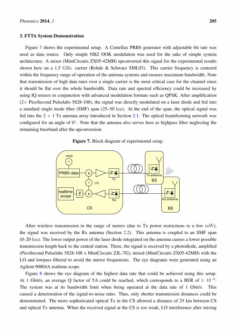
3. FTTA System Demonstration
Figure 7 shows the experimental setup. A Centellax PRBS generator with adjustable bit rate wasused as data source. Only simple NRZ OOK modulation was used for the sake of simple systemarchitecture. A mixer (MiniCircuits ZX05-42MH) upconverted this signal for the experimental resultsshown here on a 1.5 GHz carrier (Rohde & Schwarz SML03). This carrier frequency is centeredwithin the frequency range of operation of the antenna systems and ensures maximum bandwidth. Notethat transmission of high data rates over a single carrier is the most critical case for the channel sinceit should be flat over the whole bandwidth. Data rate and spectral efficiency could be increased byusing IQ mixers in conjunction with advanced modulation formats such as QPSK. After amplification(2× PicoSecond Pulselabs 5828-108), the signal was directly modulated on a laser diode and fed intoa standard single mode fiber (SMF) span (25–50 km). At the end of the span, the optical signal wasfed into the 2 × 1 Tx antenna array introduced in Section 2.1. The optical beamforming network wasconfigured for an angle of 0◦. Note that the antenna also serves here as highpass filter neglecting theremaining baseband after the upconversion.
Figure 7. Block diagram of experimental setup.
BS
BS
CS
Tx antenna
Rx antenna
Tx
Rx
x
x
~ LO
PRBS data
~
clock
realtimescope
~~~
After wireless transmission in the range of meters (due to Tx power restrictions to a few mW),the signal was received by the Rx antenna (Section 2.2). This antenna is coupled to an SMF span(0–20 km). The lower output power of the laser diode integrated on the antenna causes a lower possibletransmission length back to the central station. There, the signal is received by a photodiode, amplified(PicoSecond Pulselabs 5828-108 + MiniCircuits ZJL-7G), mixed (MiniCircuits ZX05-42MH) with theLO and lowpass filtered to avoid the mirror frequencies. The eye diagrams were generated using anAgilent 90804A realtime scope.
Figure 8 shows the eye diagram of the highest data rate that could be achieved using this setup.At 1 Gbit/s, an average Q factor of 5.6 could be reached, which corresponds to a BER of 1 · 10−8.The system was at its bandwidth limit when being operated at the data rate of 1 Gbit/s. Thiscaused a deterioration of the signal-to-noise ratio. Thus, only shorter transmission distances could bedemonstrated. The more sophisticated optical Tx in the CS allowed a distance of 25 km between CSand optical Tx antenna. When the received signal at the CS is too weak, LO interference after mixing

Photonics 2014, 1 206
impairs the eye diagram. Therefore, the distance between Rx antenna and CS had to be set to only tensof meters for an acceptable BER.
Figure 8. Eye diagram of received signal at 1 Gbit/s.
Lowering the data rate relaxes these issues and allowed for configurations with longer optical spans.Ranges within typical metro networks were demonstrated: 45 km (CS-Tx) + 10 km (Rx-CS). Theresults are shown in Figure 9: 750 Mbit/s NRZ OOK transmission with a Q factor of 10.2 was possible.An alternative configuration with 25 km (CS-Tx) + 20 km (Rx-CS) leads to a Q factor of 8.2, alsoproviding error-free transmission.
As expected, no effects due to the antenna dispersion could be noticed. Using a carrier frequency of1.5 GHz and transmission distances of less than 60 km, also no effects of the chromatic dispersion ofthe optical fiber could be observed. The high relative bandwidth of the system of 133% should be noted.
Services with smaller bandwidth (e.g., GSM) are less vulnerable to channel issues because the channelonly has to be flat in a smaller frequency range. In addition to the electronics and the radio channel, alsothe optical channel may contribute to distortions. The setup with the carrier at 1.5 and the 2 GHz
bandwidth shows good BER results. So, for narrowband services no major impact is expected. Inaddition, from the frequency characteristic measurement no deterioration is foreseen. Note that withlower data rates (e.g., 500 Gbit/s) carrier frequencies down to 1 GHz and up to 2 GHz have been usedwithout influence on the BER.
The concept can be easily scaled to higher frequencies: Laser diodes that can be directly modulatedare available up to 40 GHz bandwidth. The level of integration can be even improved when the operating

Photonics 2014, 1 207
frequency is increased due to smaller antenna dimensions. This enables applications up to the K bandthat are very promising for satellite links. Anyway, the cost of the components (laser diodes, substrates,amplifiers, drivers, etc.) scales with frequency. Also, the fiber dispersion becomes an issue at higherfrequencies: The most prominent effect will be the phase decorrelation of the two sidebands of theoptical signal. That means, achievable transmission distances will be lower, dispersion compensationhas to be applied or single sideband modulation has to be used which increases the effort.
Figure 9. Eye diagram of received signal at 750 Mbit/s.
Higher carrier frequencies allow for higher absolute bandwidths resulting in larger data rates.Another way to increase the data rate is the use of sophisticated modulation formats such as mPSKor mQAM. For these formats, it is necessary to have IQ mixers in the upconversion and downconversionstages. However, the RF signals with advanced modulation could be transported transparently over themicrowave photonic link. No change in the fiber-coupled active Rx and Tx antennas would be necessary.Just the electronic circuits in the central station would have to be changed, i.e., equipped with IQ mixersand corresponding data sources and sinks.
To serve more than one BS, wavelength division multiplexing (WDM) techniques can be applied,i.e., lasers with different wavelengths will be used. They can be separated by WDM demultiplexers.This way, one fiber can be shared among more than 100 BS. Depending on the network architecture, ofcourse also different fibers can be deployed to the various BS.

Photonics 2014, 1 208
4. Conclusions
We have demonstrated a full-duplex up- and downlink FTTA system with integrated opticalfiber-coupled antennas. Using a carrier frequency of 1.5 GHz and simple OOK modulation, a data rateof 1 Gbit/s could be achieved. The antenna system had a huge relative bandwidth of 133% supportingthe simultaneous transmission of various wireless signals. The RoF signal was transported over up to45 km before being wirelessly transmitted and up to 20 km to the CS after the Rx antenna. This iswithin the distances of a typical optical metro network and enables new system architectures of wirelessnetworks with higher levels of centralization.
The concept can be easily scaled to higher frequencies up to the millimeter wave region. Also, longertransmission distances are possible due to the superior properties of standard single mode fibers.
Acknowledgments
The authors wish to thank the anonymous reviewers for their helpful comments.
Author Contributions
N.N. coordinated and performed the writing of the article, carried out the system measurements andcontributed to Rx and Tx antenna design. R.T. designed, implemented and measured the Tx antennaarray. S.F. was in charge of the Rx antenna design, realization and characterization. D.P. contributed toRx and Tx antenna design, system setup, measurement methods and performance assessment.
Conflicts of Interest
The authors declare no conflict of interest.
References
1. Stöhr, A.; Babiel, S.; Cannard, P.; Charbonnier, B.; van Dijk, F.; Fedderwitz, S.; Moodie, D.;Pavlovic, L.; Ponnampalam, L.; Renaud, C.; et al. Millimeter-wave photonic components forbroadband wireless systems. IEEE Trans. Microw. Theory Tech. 2010, 58, 3071–3082.
2. Insua, I.; Plettemeier, D.; Schäffer, C. Simple remote heterodyne radio-over-fiber system for gigabitper second wireless access. J. Lightwave Technol. 2010, 28, 2289–2295.
3. Yashchyshyn, Y.; Malyshev, S.; Chizh, A.; Bajurko, P.; Modelski, J. Study of active integratedphotonic antenna. In Proceedings of the IEEE 3rd European Conference on Antennas andPropagation, EuCAP 2009, Berlin, Germany, 23–27 March 2009; pp. 3507–3510.
4. Ng, W.; Walston, A.; Tangonan, G.; Lee, J.; Newberg, I.; Bernstein, N. The first demonstration ofan optically steered microwave phased array antenna using true-time-delay. J. Lightwave Technol.1991, 9, 1124–1131.
5. Corral, J.; Marti, J.; Regidor, S.; Foster, J.; Laming, R.; Cole, M. Continuously variable truetime-delay optical feeder for phased-array antenna employing chirped fiber grating. IEEE Trans.Microw. Theory Tech. 1997, 45, 1531–1536.

Photonics 2014, 1 209
6. Nanyan, N.; Ngah, R.; Prakoso, T.; Rahayu, Y.; Rahman, T. An active downlink photonicantenna. In Proceedings of the 2010 International Conference on Photonics (ICP), Langkawi,Kedah, Malaysia, 5–7 July 2010; pp. 1–5.
7. Neumann, N.; Trieb, R.; Benedix, W.S.; Plettemeier, D. Active integrated photonic antennaarray. In Proceedings of the 2012 IEEE-APS Topical Conference on Antennas and Propagation inWireless Communications (APWC), Cape Town, South Africa, 2–7 September 2012; pp. 648–651.
8. Neumann, N.; Trieb, R.; Plettemeier, D. Remotely operated active integrated photonic antennaarray. In Proceedings of the 2012 Loughborough Antennas & Propagation Conference (LAPC2012); Loughborough, Leicestershire, UK, 12–13 November 2012.
9. Westbrook, L.; Moodie, D. Simultaneous bi-directional analogue fibre-optic transmission using anelectroabsorption modulator. Electron. Lett. 1996, 32, 1806–1807.
10. Stöhr, A.; Kitayama, K.i.; Jager, D. Full-duplex fiber-optic RF subcarrier transmission using adual-function modulator/photodetector. IEEE Trans. Microw. Theory Tech. 1999, 47, 1338–1341.
11. Sittakul, V.; Cryan, M.J. A fully bidirectional 2.4-GHz wireless-over-fiber system using photonicactive integrated antennas (PhAIAs). J. Lightwave Technol. 2007, 25, 3358–3365.
12. Neumann, N.; Frach, S.; Plettemeier, D. Active integrated fiber-coupled receiving antenna.In Proceedings of the 2013 Loughborough Antennas & Propagation Conference (LAPC 2013);Loughborough, Leicestershire, UK, 11–12 November 2013.
13. Allen, B.; Dohler, M.; Okon, E.; Malik, W.; Brown, A.; Edwards, D. Ultra WidebandAntennas and Propagation for Communications, Radar and Imaging; Wiley: Oxford, UK, 2006;p. 160.
14. Pan, S.; Yao, J. A UWB over fiber system compatible with WDM-PON architecture.IEEE Photonics Technol. Lett. 2010, 22, 1500–1502.
15. Lee, M.J.; Kang, H.S.; Lee, K.H.; Choi, W.Y. Fiber-fed 60-GHz self-heterodyne system using aself-oscillating harmonic optoelectronic mixer based on a CMOS-compatible APD. In Proceedingsof the 2008 IEEE MTT-S International Conference on Microwave Symposium Digest, Atlanta, GA,USA, 15–20 June 2008; pp. 587–590.
16. Chow, C.; Kuo, F.; Shi, J.; Yeh, C.; Wu, Y.; Wang, C.; Li, Y.; Pan, C. 100 GHz ultra-wideband(UWB) fiber-to-the-antenna (FTTA) system for in-building and in-home networks. Optics Express2010, 18, 473–478.
17. Tang, C.; Yu, J.; Li, X.; Chi, N.; Xiao, J.; Tian, Y.; Zhang, J. A 30 Gb/s full-duplex bi-directionaltransmission optical wireless-over fiber integration system at W-band. Opt. Express 2014,22, 239–245.
18. Fang, W.J.; Huang, X.G.; Yang, K.; Zhang, X.M. Full duplex dense-wavelength-division-multiplexing radio-over-fiber system transmission of 75-GHz W-band frequency multiple-inputmultiple-output orthogonal-frequency-division-multiplexing signals with 3× 12 Gbps downstreamand 6 Gbps upstream. Opt. Eng. 2012, 51, 095004–1.
19. Anna, L.; Konrad, G.; Yevhen, Y.; Józef, M. Design and investigation of photonic remote antennaunits for bidirectional transmission in the last mile wireless over fiber system. Radioengineering2013, 22, 1239.

Photonics 2014, 1 210
20. Deal, W.R.; Radisic, V.; Qian, Y.; Itoh, T. Integrated-antenna push-pull power amplifiers.IEEE Trans. Microw. Theory Techn. 1999, 47, 1418–1425.
c© 2014 by the authors; licensee MDPI, Basel, Switzerland. This article is an open access articledistributed under the terms and conditions of the Creative Commons Attribution license(http://creativecommons.org/licenses/by/3.0/).