Photomicrography
73
Instant Photography Photomicrography Through the Microscope P O L A R O I D
-
Upload
anastatata -
Category
Documents
-
view
24 -
download
0
description
microscope & photography
Transcript of Photomicrography

Instant Photography
PhotomicrographyThrough the Microscope
P O
L A
R O
I D
Instant Photography
PhotomicrographyThrough the Microscope
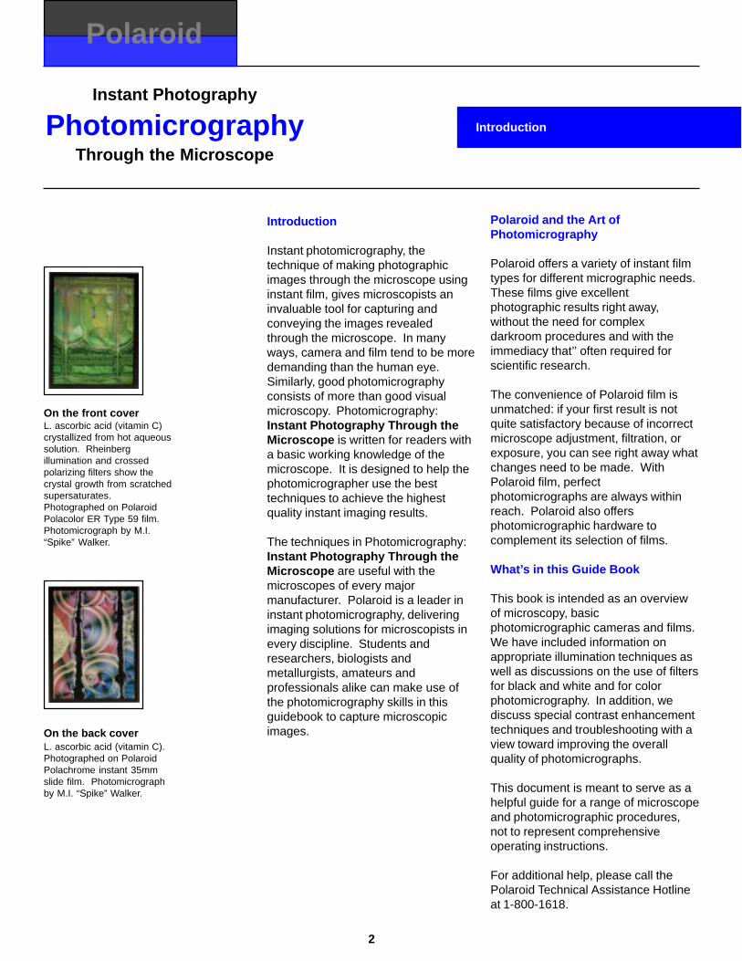
Introduction
Polaroid
Introduction
Instant photomicrography, thetechnique of making photographicimages through the microscope usinginstant film, gives microscopists aninvaluable tool for capturing andconveying the images revealedthrough the microscope. In manyways, camera and film tend to be moredemanding than the human eye.Similarly, good photomicrographyconsists of more than good visualmicroscopy. Photomicrography:Instant Photography Through theMicroscope is written for readers witha basic working knowledge of themicroscope. It is designed to help thephotomicrographer use the besttechniques to achieve the highestquality instant imaging results.
The techniques in Photomicrography:Instant Photography Through theMicroscope are useful with themicroscopes of every majormanufacturer. Polaroid is a leader ininstant photomicrography, deliveringimaging solutions for microscopists inevery discipline. Students andresearchers, biologists andmetallurgists, amateurs andprofessionals alike can make use ofthe photomicrography skills in thisguidebook to capture microscopicimages.
Polaroid and the Art ofPhotomicrography
Polaroid offers a variety of instant filmtypes for different micrographic needs.These films give excellentphotographic results right away,without the need for complexdarkroom procedures and with theimmediacy that’’ often required forscientific research.
The convenience of Polaroid film isunmatched: if your first result is notquite satisfactory because of incorrectmicroscope adjustment, filtration, orexposure, you can see right away whatchanges need to be made. WithPolaroid film, perfectphotomicrographs are always withinreach. Polaroid also offersphotomicrographic hardware tocomplement its selection of films.
What’s in this Guide Book
This book is intended as an overviewof microscopy, basicphotomicrographic cameras and films.We have included information onappropriate illumination techniques aswell as discussions on the use of filtersfor black and white and for colorphotomicrography. In addition, wediscuss special contrast enhancementtechniques and troubleshooting with aview toward improving the overallquality of photomicrographs.
This document is meant to serve as ahelpful guide for a range of microscopeand photomicrographic procedures,not to represent comprehensiveoperating instructions.
For additional help, please call thePolaroid Technical Assistance Hotlineat 1-800-1618.
On the back coverL. ascorbic acid (vitamin C).Photographed on PolaroidPolachrome instant 35mmslide film. Photomicrographby M.I. “Spike” Walker.
On the front coverL. ascorbic acid (vitamin C)crystallized from hot aqueoussolution. Rheinbergillumination and crossedpolarizing filters show thecrystal growth from scratchedsupersaturates.Photographed on PolaroidPolacolor ER Type 59 film.Photomicrograph by M.I.“Spike” Walker.
2

Instant Photography
PhotomicrographyThrough the Microscope
Table of Contents
Polaroid
3
Microscopes and Cameras for Photomicrography
Introduction ................................................................................................................................................................ 5Basic Components of the Compound Microscope ..................................................................................................... 7Understanding Aberrations ........................................................................................................................................ 8What is Numerical Aperture? ..................................................................................................................................... 9Cameras for Photomicrography ................................................................................................................................. 11Setting up the Microscope and Camera to Create Instant 35mm Slides .................................................................... 12Understanding Parfocalization ................................................................................................................................... 12The Camera Magnification Factor and Photographic Magnification ........................................................................... 13Controlling Exposure in Photomicrography ................................................................................................................ 14Setting Up Your Microscope for Photography ............................................................................................................ 14
Kohler Illumination
Introduction ................................................................................................................................................................ 15Understanding Kohler Illumination as Two Paths of Light .......................................................................................... 16Microscope Components that Provide Kohler Illumination ......................................................................................... 17Adjustments to the Microscope for Kohler Illumination .............................................................................................. 18Aligning and Focusing the Substage Condenser and the Field Diaphragm ............................................................... 18Controlling the Size of the Aperture Diaphragm ......................................................................................................... 19Centering the Aperture Diaphragm ............................................................................................................................ 19Manually Aligning the Light Source ............................................................................................................................ 20The Condenser’s Illuminating Cone ........................................................................................................................... 21Typical Field Views for Kohler Illumination ................................................................................................................. 21The Reflected Light Microscope ................................................................................................................................ 22Setting Up Kohler Illumination for a Reflected Light Microscope ................................................................................ 22
Further Understanding Kohler Illumination
Introduction ................................................................................................................................................................ 23How the Specimen Affects Light ................................................................................................. ............................... 24Controlling Light and Image Quality ........................................................................................................................... 25The Mix of Deflected and Direct Light ........................................................................................................................ 25The Effect of Aperture Setting on Image Quality ........................................................................................................ 26Determining the Best Aperture Diaphragm Setting .................................................................................................... 28The Aperture Diaphragm and Its Effect on Depth of Field ......................................................................................... 28
Instant Film Characteristics for Photomicrography
Introduction ................................................................................................................................................................ 29Film Speed Choices .................................................................................................................................................. 30Photographic Image Resolution ................................................................................................................................. 30Contrast ..................................................................................................................................................................... 30Color Temperature ..................................................................................................................................................... 31Spectral Sensitivity of Instant Films ........................................................................................................................... 32Reciprocity Failure in Black and White Films ............................................................................................................. 32Reciprocity Failure in Color Films .............................................................................................................................. 32Using a Graduated Exposure Test Strip ..................................................................................................................... 34

Instant Photography
PhotomicrographyThrough the Microscope
4
Using Filters for Black and White Photomicrography
Introduction ................................................................................................................................................................ 35Where to Obtain Filters.............................................................................................................................................. 36Placing Filters in Your Microscope ............................................................................................................................. 36Understanding Filter Factors ..................................................................................................................................... 36Filtration for Optimum Image Resolution ................................................................................................................... 37Using Filters for Contrast Control .............................................................................................................................. 38Selecting Filters for Contrast Control ......................................................................................................................... 39Filter and Stain Techniques ....................................................................................................................................... 41Using Interference Filters .......................................................................................................................................... 42Using Neutral Density Filters ..................................................................................................................................... 42Using Heat-Absorbing Filters ..................................................................................................................................... 42Using Ultraviolet-Absorbing Filters ............................................................................................................................. 42
Using Filters for Color Photomicrography
Introduction ................................................................................................................................................................ 43The Relationship of Color Film, Illumination, Exposure Time and Filters ................................................................... 44Establishing a Standard Exposure Time for Standard Filtration ................................................................................. 44The Effect of Lamp Voltage and Exposure Duration on Color Balance ...................................................................... 45Placing Filters in Your Microscope ............................................................................................................................. 45Filters for Color Photomicrography ............................................................................................................................ 46Color-Conversion and Light-Balancing Filters ............................................................................................................ 46Color Imbalances ...................................................................................................................................................... 49Ultraviolet-Absorbing Filters ....................................................................................................................................... 50Didymium Filters ........................................................................................................................................................ 50Heat-Absorbing Filters ............................................................................................................................................... 50Neutral Density Filters ............................................................................................................................................... 51Sample Applications of Color Filters .......................................................................................................................... 52
Special Contrast-Enhancement Techniques
Introduction ................................................................................................................................................................ 53Polarized Light ........................................................................................................................................................... 55Darkfield Illumination ................................................................................................................................................. 56Reflected Light Darkfield ........................................................................................................................................... 56Phase-Contrast Illumination ....................................................................................................................................... 58Hoffman Modulation Contrast .................................................................................................................................... 60Differential Interference Contrast ............................................................................................. .................................. 62Reflected Light differential Interference Contrast ....................................................................................................... 64
Troubleshooting Common Problems ................................................................................................ ..................... 65
Instant Films for Photomicrography ............................................................................................. ......................... 69

Instant Photography
PhotomicrographyThrough the Microscope
Microscopes and Camerasfor Photomicrography
Polaroid
5
Introduction
Throughout the world, in laboratories,factories, classrooms and hospitals,microscopes are used to provideinsight into materials, processes anddynamic events. Since 1958, Polaroidhas been an important partner to themicroscopist, providing instantphotomicrographs. Polaroid films, filmholders and cameras allow themicroscopist to instantly documentwhat is seen in the microscope and toshare that view with others.
Menthol, 10xPolanPan CTYoko Miyake
Instant Photography
PhotomicrographyThrough the Microscope
6
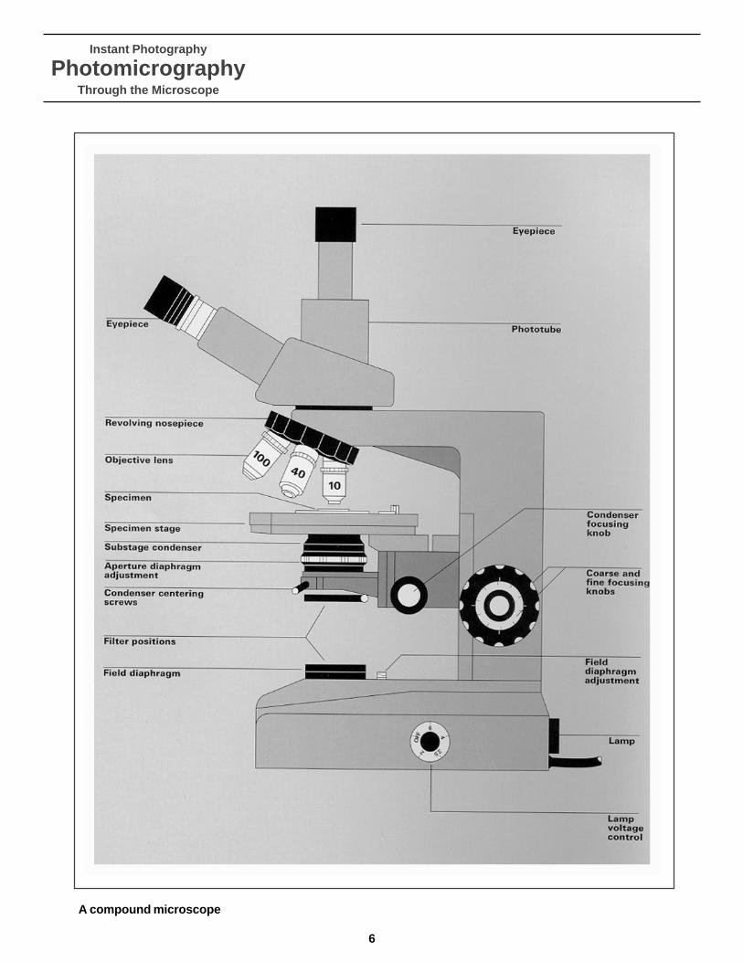
A compound microscope
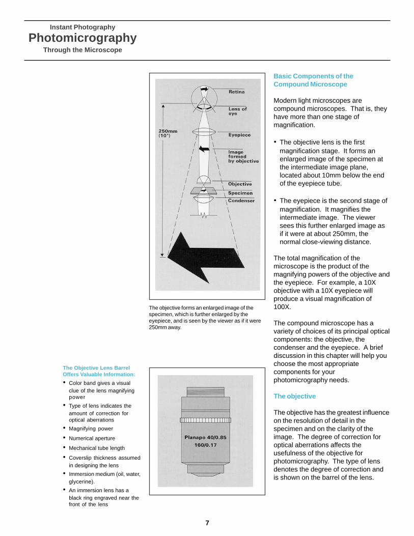
Basic Components of theCompound Microscope
Modern light microscopes arecompound microscopes. That is, theyhave more than one stage ofmagnification.
• The objective lens is the firstmagnification stage. It forms anenlarged image of the specimen atthe intermediate image plane,located about 10mm below the endof the eyepiece tube.
• The eyepiece is the second stage ofmagnification. It magnifies theintermediate image. The viewersees this further enlarged image asif it were at about 250mm, thenormal close-viewing distance.
The total magnification of themicroscope is the product of themagnifying powers of the objective andthe eyepiece. For example, a 10Xobjective with a 10X eyepiece willproduce a visual magnification of100X.
The compound microscope has avariety of choices of its principal opticalcomponents: the objective, thecondenser and the eyepiece. A briefdiscussion in this chapter will help youchoose the most appropriatecomponents for yourphotomicrography needs.
The objective
The objective has the greatest influenceon the resolution of detail in thespecimen and on the clarity of theimage. The degree of correction foroptical aberrations affects theusefulness of the objective forphotomicrography. The type of lensdenotes the degree of correction andis shown on the barrel of the lens.
Instant Photography
PhotomicrographyThrough the Microscope
The Objective Lens BarrelOffers Valuable Information:
• Color band gives a visualclue of the lens magnifyingpower
• Type of lens indicates theamount of correction foroptical aberrations
• Magnifying power
• Numerical aperture
• Mechanical tube length
• Coverslip thickness assumedin designing the lens
• Immersion medium (oil, water,glycerine).
• An immersion lens has ablack ring engraved near thefront of the lens
The objective forms an enlarged image of thespecimen, which is further enlarged by theeyepiece, and is seen by the viewer as if it were250mm away.
7
Instant Photography
PhotomicrographyThrough the Microscope
8
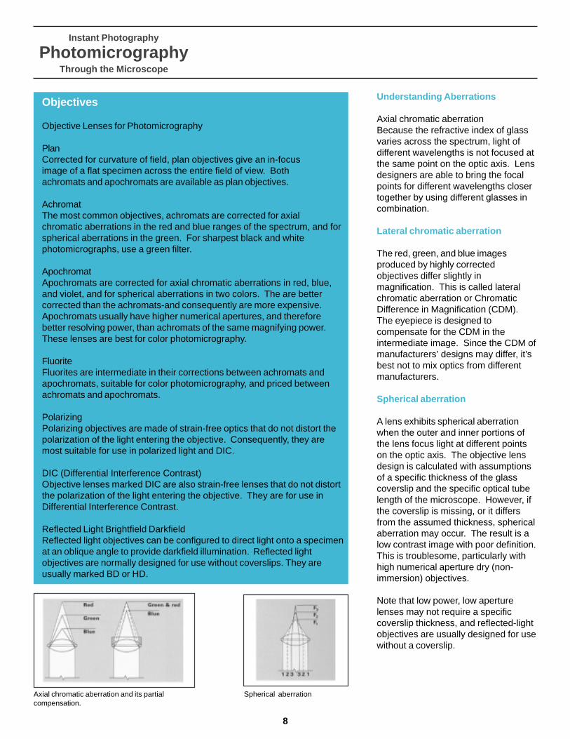
Objectives
Objective Lenses for Photomicrography
PlanCorrected for curvature of field, plan objectives give an in-focusimage of a flat specimen across the entire field of view. Bothachromats and apochromats are available as plan objectives.
AchromatThe most common objectives, achromats are corrected for axialchromatic aberrations in the red and blue ranges of the spectrum, and forspherical aberrations in the green. For sharpest black and whitephotomicrographs, use a green filter.
ApochromatApochromats are corrected for axial chromatic aberrations in red, blue,and violet, and for spherical aberrations in two colors. The are bettercorrected than the achromats-and consequently are more expensive.Apochromats usually have higher numerical apertures, and thereforebetter resolving power, than achromats of the same magnifying power.These lenses are best for color photomicrography.
FluoriteFluorites are intermediate in their corrections between achromats andapochromats, suitable for color photomicrography, and priced betweenachromats and apochromats.
PolarizingPolarizing objectives are made of strain-free optics that do not distort thepolarization of the light entering the objective. Consequently, they aremost suitable for use in polarized light and DIC.
DIC (Differential Interference Contrast)Objective lenses marked DIC are also strain-free lenses that do not distortthe polarization of the light entering the objective. They are for use inDifferential Interference Contrast.
Reflected Light Brightfield DarkfieldReflected light objectives can be configured to direct light onto a specimenat an oblique angle to provide darkfield illumination. Reflected lightobjectives are normally designed for use without coverslips. They areusually marked BD or HD.
Understanding Aberrations
Axial chromatic aberrationBecause the refractive index of glassvaries across the spectrum, light ofdifferent wavelengths is not focused atthe same point on the optic axis. Lensdesigners are able to bring the focalpoints for different wavelengths closertogether by using different glasses incombination.
Lateral chromatic aberration
The red, green, and blue imagesproduced by highly correctedobjectives differ slightly inmagnification. This is called lateralchromatic aberration or ChromaticDifference in Magnification (CDM).The eyepiece is designed tocompensate for the CDM in theintermediate image. Since the CDM ofmanufacturers’ designs may differ, it’sbest not to mix optics from differentmanufacturers.
Spherical aberration
A lens exhibits spherical aberrationwhen the outer and inner portions ofthe lens focus light at different pointson the optic axis. The objective lensdesign is calculated with assumptionsof a specific thickness of the glasscoverslip and the specific optical tubelength of the microscope. However, ifthe coverslip is missing, or it differsfrom the assumed thickness, sphericalaberration may occur. The result is alow contrast image with poor definition.This is troublesome, particularly withhigh numerical aperture dry (non-immersion) objectives.
Note that low power, low aperturelenses may not require a specificcoverslip thickness, and reflected-lightobjectives are usually designed for usewithout a coverslip.
Axial chromatic aberration and its partialcompensation.
Spherical aberration
Instant Photography
PhotomicrographyThrough the Microscope
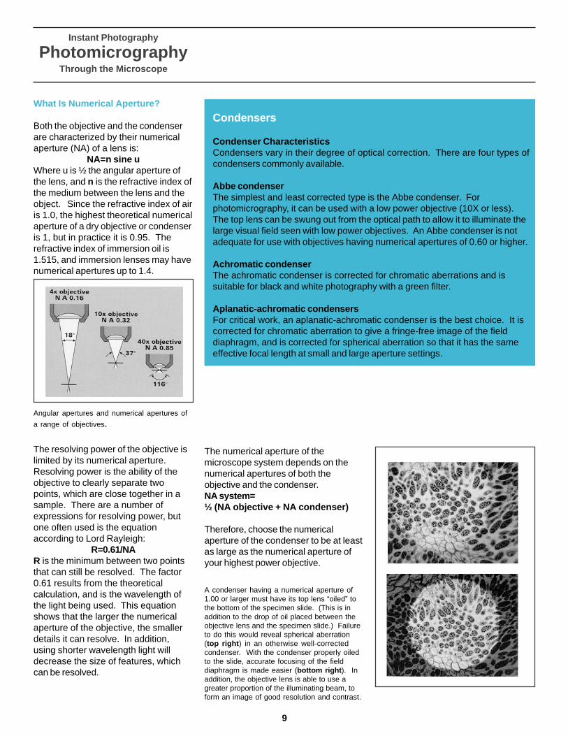
What Is Numerical Aperture?
Both the objective and the condenserare characterized by their numericalaperture (NA) of a lens is:
NA=n sine uWhere u is ½ the angular aperture ofthe lens, and n is the refractive index ofthe medium between the lens and theobject. Since the refractive index of airis 1.0, the highest theoretical numericalaperture of a dry objective or condenseris 1, but in practice it is 0.95. Therefractive index of immersion oil is1.515, and immersion lenses may havenumerical apertures up to 1.4.
The resolving power of the objective islimited by its numerical aperture.Resolving power is the ability of theobjective to clearly separate twopoints, which are close together in asample. There are a number ofexpressions for resolving power, butone often used is the equationaccording to Lord Rayleigh:
R=0.61/NAR is the minimum between two pointsthat can still be resolved. The factor0.61 results from the theoreticalcalculation, and is the wavelength ofthe light being used. This equationshows that the larger the numericalaperture of the objective, the smallerdetails it can resolve. In addition,using shorter wavelength light willdecrease the size of features, whichcan be resolved.
Condensers
Condenser CharacteristicsCondensers vary in their degree of optical correction. There are four types ofcondensers commonly available.
Abbe condenserThe simplest and least corrected type is the Abbe condenser. Forphotomicrography, it can be used with a low power objective (10X or less).The top lens can be swung out from the optical path to allow it to illuminate thelarge visual field seen with low power objectives. An Abbe condenser is notadequate for use with objectives having numerical apertures of 0.60 or higher.
Achromatic condenserThe achromatic condenser is corrected for chromatic aberrations and issuitable for black and white photography with a green filter.
Aplanatic-achromatic condensersFor critical work, an aplanatic-achromatic condenser is the best choice. It iscorrected for chromatic aberration to give a fringe-free image of the fielddiaphragm, and is corrected for spherical aberration so that it has the sameeffective focal length at small and large aperture settings.
Angular apertures and numerical apertures of
a range of objectives.
The numerical aperture of themicroscope system depends on thenumerical apertures of both theobjective and the condenser.NA system=½ (NA objective + NA condenser)
Therefore, choose the numericalaperture of the condenser to be at leastas large as the numerical aperture ofyour highest power objective.
A condenser having a numerical aperture of1.00 or larger must have its top lens “oiled” tothe bottom of the specimen slide. (This is inaddition to the drop of oil placed between theobjective lens and the specimen slide.) Failureto do this would reveal spherical aberration(top right ) in an otherwise well-correctedcondenser. With the condenser properly oiledto the slide, accurate focusing of the fielddiaphragm is made easier (bottom right ). Inaddition, the objective lens is able to use agreater proportion of the illuminating beam, toform an image of good resolution and contrast.
9

Instant Photography
PhotomicrographyThrough the Microscope
10
Eyepiece
Eyepiece Characteristics
Magnifying PowerThe magnifying power of an eyepiece is marked by a number followed by an X.Eyepieces range in power from 2X to 20X.
Field of ViewThe field of view number follows the magnifying power. It shows the diameter inmm of the primary image that is magnified by the eyepiece.
Eyepoint of Exit PupilThe eyepoint, or exit pupil, of the microscope is the point above the eyepiecewhere the image comes to its smallest diameter. The pupil of your eye ispositioned at the eyepoint during observation. Note that high eyepointeyepieces provide a more comfortable view if you wear eyeglasses. Look for asymbol of spectacles on the equipment.
Compensating EyepieceCompensating eyepieces correct for the Chromatic Difference in Magnificationin the intermediate image produced by highly corrected objectives. Theyshould be used with all plan objectives and with fluorites and achromats.Compensating eyepieces are designated by K, C, or Comp. They can beidentified by a yellowish fringe at the periphery of the image.
Adjustable EyepieceAdjustable eyepieces have an eyelens, which can be used to focus on a reticlepositioned at the intermediate image plane. When used in the viewingeyepiece, adjust the eyelens so that the reticle is in sharp focus beforefocusing the specimen. It is convenient to use an adjustable eyepiece in thephototube when shooting photomicrographs with a bellows camera.
Projection EyepieceA projection eyepiece cannot be used for normal viewing. It is used forphotomicrography with cameras that use no other lenses between theprojection lens and the film plane. Some projection eyepieces are adjustablefor different distances to the film plane while others may be fixed for a specificdistance.
Diagram showing eyepoint, the eyelens, thefield lens, and the diaphragm defining theintermediate image plane.
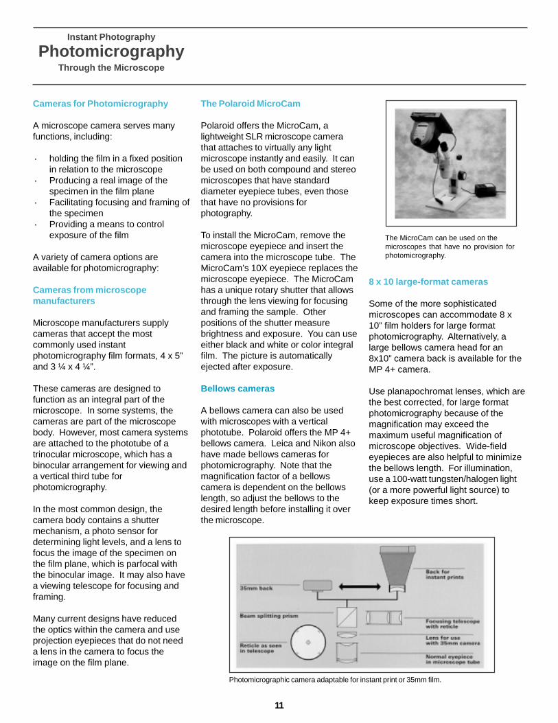
Cameras for Photomicrography
A microscope camera serves manyfunctions, including:
· holding the film in a fixed positionin relation to the microscope
· Producing a real image of thespecimen in the film plane
· Facilitating focusing and framing ofthe specimen
· Providing a means to controlexposure of the film
A variety of camera options areavailable for photomicrography:
Cameras from microscopemanufacturers
Microscope manufacturers supplycameras that accept the mostcommonly used instantphotomicrography film formats, 4 x 5”and 3 ¼ x 4 ¼”.
These cameras are designed tofunction as an integral part of themicroscope. In some systems, thecameras are part of the microscopebody. However, most camera systemsare attached to the phototube of atrinocular microscope, which has abinocular arrangement for viewing anda vertical third tube forphotomicrography.
In the most common design, thecamera body contains a shuttermechanism, a photo sensor fordetermining light levels, and a lens tofocus the image of the specimen onthe film plane, which is parfocal withthe binocular image. It may also havea viewing telescope for focusing andframing.
Many current designs have reducedthe optics within the camera and useprojection eyepieces that do not needa lens in the camera to focus theimage on the film plane.
Instant Photography
PhotomicrographyThrough the Microscope
The Polaroid MicroCam
Polaroid offers the MicroCam, alightweight SLR microscope camerathat attaches to virtually any lightmicroscope instantly and easily. It canbe used on both compound and stereomicroscopes that have standarddiameter eyepiece tubes, even thosethat have no provisions forphotography.
To install the MicroCam, remove themicroscope eyepiece and insert thecamera into the microscope tube. TheMicroCam’s 10X eyepiece replaces themicroscope eyepiece. The MicroCamhas a unique rotary shutter that allowsthrough the lens viewing for focusingand framing the sample. Otherpositions of the shutter measurebrightness and exposure. You can useeither black and white or color integralfilm. The picture is automaticallyejected after exposure.
Bellows cameras
A bellows camera can also be usedwith microscopes with a verticalphototube. Polaroid offers the MP 4+bellows camera. Leica and Nikon alsohave made bellows cameras forphotomicrography. Note that themagnification factor of a bellowscamera is dependent on the bellowslength, so adjust the bellows to thedesired length before installing it overthe microscope.
8 x 10 large-format cameras
Some of the more sophisticatedmicroscopes can accommodate 8 x10” film holders for large formatphotomicrography. Alternatively, alarge bellows camera head for an8x10” camera back is available for theMP 4+ camera.
Use planapochromat lenses, which arethe best corrected, for large formatphotomicrography because of themagnification may exceed themaximum useful magnification ofmicroscope objectives. Wide-fieldeyepieces are also helpful to minimizethe bellows length. For illumination,use a 100-watt tungsten/halogen light(or a more powerful light source) tokeep exposure times short.
Photomicrographic camera adaptable for instant print or 35mm film.
The MicroCam can be used on themicroscopes that have no provision forphotomicrography.
11
Instant Photography
PhotomicrographyThrough the Microscope
12
Setting Up the Microscope andCamera to Create Instant 35mmSlides
You can make instantphotomicrographic slides with Polaroidinstant 35mm transparency films,Polachrome, Polachrome HC,Polapan, and Polagraph. (See the filmchart on pages 70-71). Most camerasystems supplied by microscopemanufacturers accept a 35mm back.
An SLR 35mm camera can beattached to the microscope with a T-mount adapter and a microscope tubeadapter. The T-mount adapter isspecific for the lens mount mechanismof your 35mm camera. It should bejoined to the tube adapter which holdsthe microscope eyepiece and locks onthe microscope eyepiece tube. The T-mount adapter is available fromcamera manufacturers, microscopemanufacturers, or scientific supplyhouses. For framing, use the SLRviewing screen of the camera and themicroscope focus control. Expose thefilm with the camera focal planeshutter. Since exposure is controlledonly by time, se t the exposure controlto the “aperture preferred” mode.
Focusing and framing
Microscope cameras provide one ofthe three methods for ensuring properfocus of the specimen in the filmplane:
· A viewing telescope in the camerabody, which is parfocal with thefilm plane of the camera. Thetelescope contains a reticle with adouble cross hair. It is helpful,especially at low magnifications, touse a focusing magnifier inconjunction with the viewing andtelescope to critically focus thereticle and then the specimen.
· Some cameras use an adjustableeyepiece with a focusing eyelensand a reticle delineating the areaof the photomicrograph as one ofthe binocular eyepieces. It isimportant that the reticle be insharp focus before focusing thespecimen.
· A ground glass screen at the filmplane may also be used forfocusing, but it has thedisadvantage of low light levels atthe film plane. This maynecessitate dimming room lightsfor focusing.
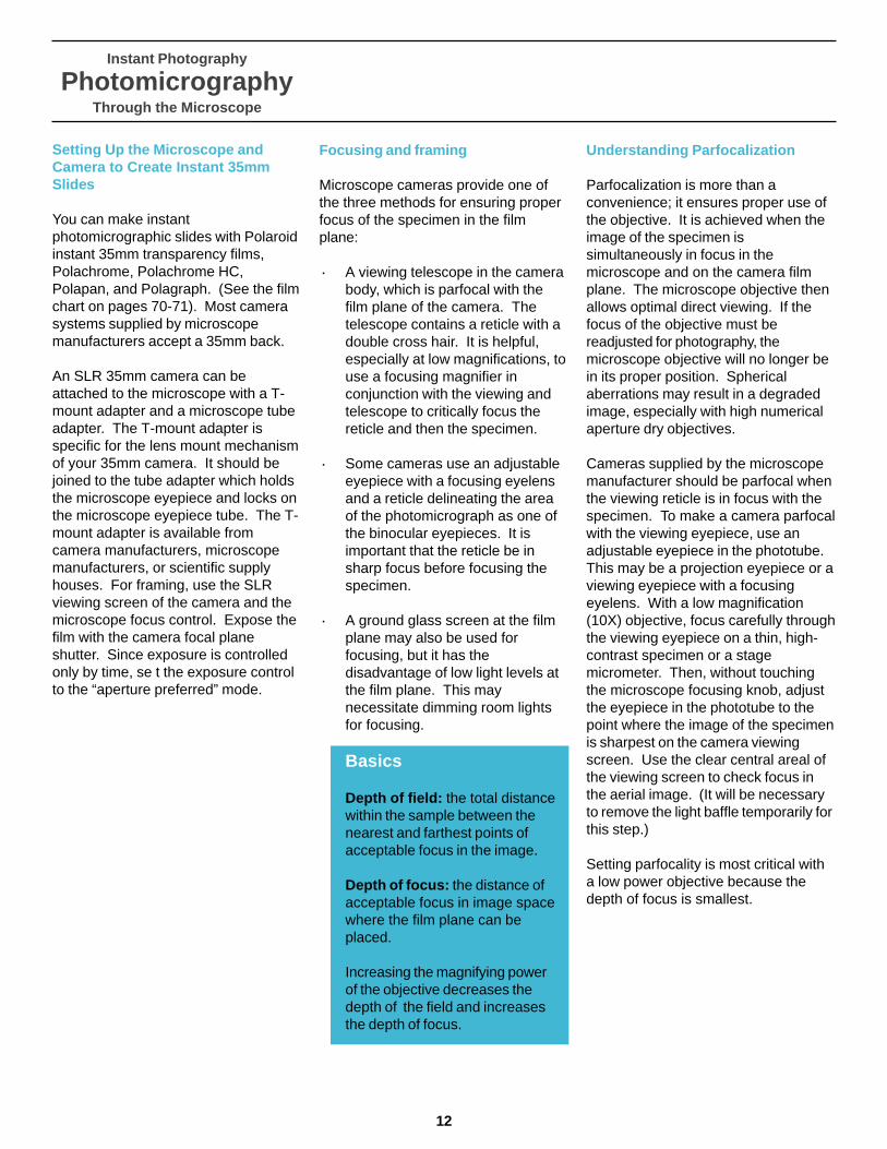
Basics
Depth of field: the total distancewithin the sample between thenearest and farthest points ofacceptable focus in the image.
Depth of focus: the distance ofacceptable focus in image spacewhere the film plane can beplaced.
Increasing the magnifying powerof the objective decreases thedepth of the field and increasesthe depth of focus.
Understanding Parfocalization
Parfocalization is more than aconvenience; it ensures proper use ofthe objective. It is achieved when theimage of the specimen issimultaneously in focus in themicroscope and on the camera filmplane. The microscope objective thenallows optimal direct viewing. If thefocus of the objective must bereadjusted for photography, themicroscope objective will no longer bein its proper position. Sphericalaberrations may result in a degradedimage, especially with high numericalaperture dry objectives.
Cameras supplied by the microscopemanufacturer should be parfocal whenthe viewing reticle is in focus with thespecimen. To make a camera parfocalwith the viewing eyepiece, use anadjustable eyepiece in the phototube.This may be a projection eyepiece or aviewing eyepiece with a focusingeyelens. With a low magnification(10X) objective, focus carefully throughthe viewing eyepiece on a thin, high-contrast specimen or a stagemicrometer. Then, without touchingthe microscope focusing knob, adjustthe eyepiece in the phototube to thepoint where the image of the specimenis sharpest on the camera viewingscreen. Use the clear central areal ofthe viewing screen to check focus inthe aerial image. (It will be necessaryto remove the light baffle temporarily forthis step.)
Setting parfocality is most critical witha low power objective because thedepth of focus is smallest.

Instant Photography
PhotomicrographyThrough the Microscope
The Camera Magnification Factorand Photographic Magnification
The visual magnification of amicroscope is the product of themagnifying powers of the objective andthe eyepiece. Photographicmagnification is determined by themicroscope magnification and themagnification factor of the camera.
With a bellows camera, the cameramagnification factor is dependent onthe bellows length, which is thedistance from the eyepoint of theocular to the film plane (also calledprojection distance). The cameramagnification factor is equal to thebellows length (in millimeters) dividedby 250mm, the reference distance forvisual magnification. Thus, when theprojection distance is 250mm, thecamera magnification factor is 1X, andthe photographic magnification isequal to the visual magnification.
Most cameras for 4 x 5” or 3 1/4 x 4 ¼”formats have a magnification factorbetween 0.8X and 1.25X, and thatfactor is marked on the camera itself.Some currently available camerasdesigned for use with projectioneyepieces (of low magnifying power)have a larger camera factor 3X or 4X.As an illustration, the following twosystems will each give photographicmagnification of 200X:
· A 20X objective used with a 10Xeyepiece and a camera factor of1X.
· A 20X objective used with a 2.5Xprojection eyepiece and a camerafactor of 4X.
A 35mm camera usually has a smallermagnification factor (0.25X to 0.5X)because of the shorter projectiondistance. However, the image on theslide is subsequently enlarged inprinting or projection.
Determining exact magnification
Microscope objectives may differ fromtheir nominal magnifying power by afew percent. If you are making criticalmeasurements on your micrographsand want to know the exactmagnification, photograph a stagemicrometer and measure thephotomicrograph directly.
Controlling Exposure inPhotomicrography
Photographic exposure is the length oftime that the shutter remains open.For photomicrography, camerasystems with automatic exposurecontrol offer greatest flexibility andefficiency. In general, older or lessexpensive automatic camerasmeasure the amount of light in thewhole image and determine exposurebased on the average brightness. Thedesign is ideal for specimens ofuniform brightness. However, non-uniform specimens may require someadjustment of exposure. Moresophisticated cameras offer a choiceof averaging mode or spot-meteringmode that measures the brightness ina selected spot and automaticallyregisters the best exposure for thatarea.
Simple microscope cameras pride onlya shutter for manual exposure control;however, consistent exposures arepossible with such simple cameras ifyou standardize your conditions forphotomicrography. Use the graduatedtest strip described on page 32 to findoptimum exposure. Keep a record ofthe type of specimen, lamp voltage,magnification, filtration, contrasttechniques, and speed of the film.
Successful Photomicrography Tips
· When working with a specimenthat is not uniformly bright, you canmodify the camera’s automaticexposure setting to correct theexposure. For example, if yourspecimen has small, bright particleson a dark background, the averagebrightness will be low and thecamera will give too much exposure.You can either reduce the exposurefactor using a feature available onsome microscope cameras, or setthe camera for a higher film speedvalue than what you’re actuallyusing.
13
Instant Photography
PhotomicrographyThrough the Microscope
14
Setting Up Your Microscope forPhotography
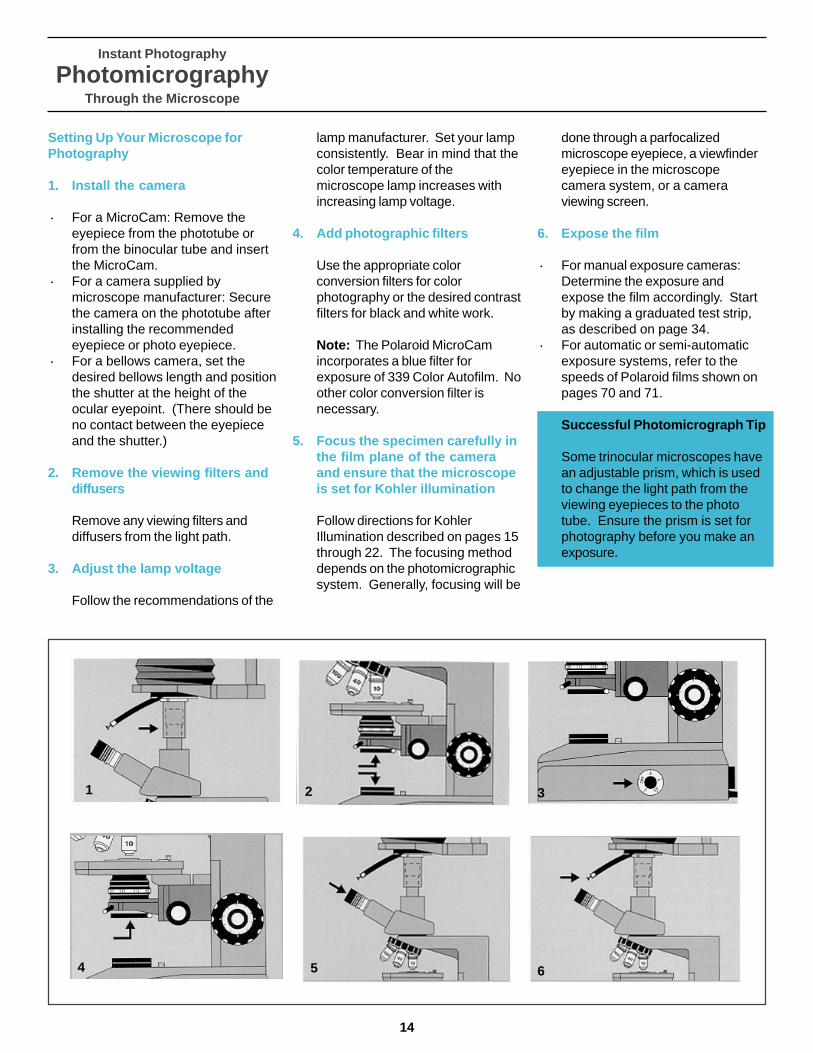
1. Install the camera
· For a MicroCam: Remove theeyepiece from the phototube orfrom the binocular tube and insertthe MicroCam.
· For a camera supplied bymicroscope manufacturer: Securethe camera on the phototube afterinstalling the recommendedeyepiece or photo eyepiece.
· For a bellows camera, set thedesired bellows length and positionthe shutter at the height of theocular eyepoint. (There should beno contact between the eyepieceand the shutter.)
2. Remove the viewing filters anddiffusers
Remove any viewing filters anddiffusers from the light path.
3. Adjust the lamp voltage
Follow the recommendations of the
lamp manufacturer. Set your lampconsistently. Bear in mind that thecolor temperature of themicroscope lamp increases withincreasing lamp voltage.
4. Add photographic filters
Use the appropriate colorconversion filters for colorphotography or the desired contrastfilters for black and white work.
Note: The Polaroid MicroCamincorporates a blue filter forexposure of 339 Color Autofilm. Noother color conversion filter isnecessary.
5. Focus the specimen carefully inthe film plane of the cameraand ensure that the microscopeis set for Kohler illumination
Follow directions for KohlerIllumination described on pages 15through 22. The focusing methoddepends on the photomicrographicsystem. Generally, focusing will be
done through a parfocalizedmicroscope eyepiece, a viewfindereyepiece in the microscopecamera system, or a cameraviewing screen.
6. Expose the film
· For manual exposure cameras:Determine the exposure andexpose the film accordingly. Startby making a graduated test strip,as described on page 34.
· For automatic or semi-automaticexposure systems, refer to thespeeds of Polaroid films shown onpages 70 and 71.
Successful Photomicrograph Tip
Some trinocular microscopes havean adjustable prism, which is usedto change the light path from theviewing eyepieces to the phototube. Ensure the prism is set forphotography before you make anexposure.
1 2 3
4 5 6

Instant Photography
PhotomicrographyThrough the Microscope
Kohler Illumination
Polaroid
15
Introduction
Camera and film are in many waysmore demanding than the human eye,so that good photography through themicroscope consists of more thangood visual microscopy.
Illumination is the most critical elementin high-quality microscopy andphotomicrography. With carefulattention to illumination, you can revealthe full color and detail of a specimenand produce the bestphotomicrographs. To produce asatisfactory image, you must meetspecial illumination criteria, adjust themicroscope carefully, and aligncomponents properly.
In 1893, August Kohler of the CarlZeiss organization developed amethod for producing optimumillumination conditions in the lightmicroscope.
Kohler Illumination is essential forquality photomicrography at highmagnifications. Without it, the sampleis not uniformly illuminated, there isinsufficient light intensity at the filmplane, and the objective lens isseverely limited in its ability to resolvefine detail.
ArctiumLappa stern,50xPolaPan CTCristina Zeni
Instant Photography
PhotomicrographyThrough the Microscope
16
Understanding Kohler Illuminationas Two Paths of Light
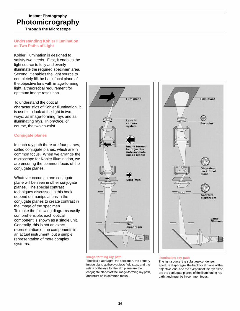
Kohler Illumination is designed tosatisfy two needs. First, it enables thelight source to fully and evenlyilluminate the required specimen area.Second, it enables the light source tocompletely fill the back focal plane ofthe objective lens with image-forminglight, a theoretical requirement foroptimum image resolution.
To understand the opticalcharacteristics of Kohler Illumination, itis useful to look at the light in twoways: as image-forming rays and asilluminating rays. In practice, ofcourse, the two co-exist.
Conjugate planes
In each ray path there are four planes,called conjugate planes, which are incommon focus. When we arrange themicroscope for Kohler Illumination, weare ensuring the common focus of theconjugate planes.
Whatever occurs in one conjugateplane will be seen in other conjugateplanes. The special contrasttechniques discussed in this bookdepend on manipulations in theconjugate planes to create contrast inthe image of the specimen.To make the following diagrams easilycomprehensible, each opticalcomponent is shown as a single unit.Generally, this is not an exactrepresentation of the components inan actual instrument, but a simplerepresentation of more complexsystems.
Image-forming ray pathThe field diaphragm, the specimen, the primaryimage plane at the eyepiece field stop, and theretina of the eye for the film plane are theconjugate planes of the image-forming ray path,and must be in common focus.
Illuminating ray pathThe light source, the substage condenseraperture diaphragm, the back focal plane of theobjective lens, and the eyepoint of the eyepieceare the conjugate planes of the illuminating raypath, and must be in common focus.
Instant Photography
PhotomicrographyThrough the Microscope
Microscope Components ThatProvide Kohler Illumination
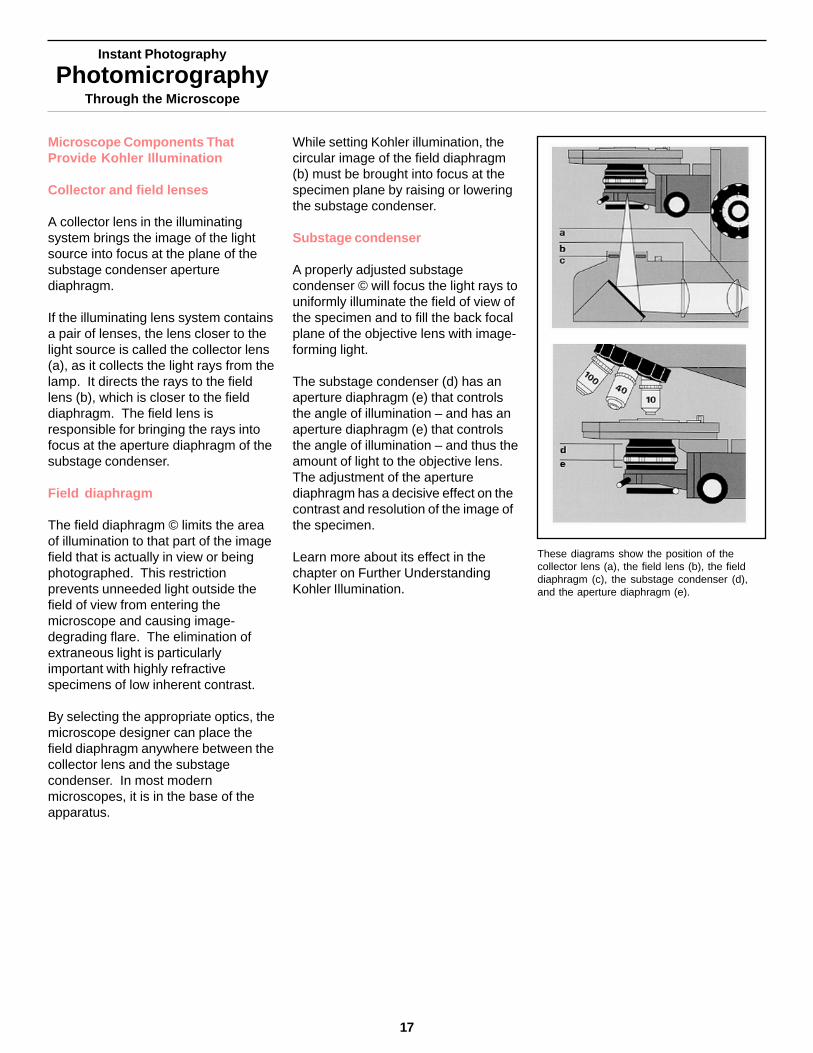
Collector and field lenses
A collector lens in the illuminatingsystem brings the image of the lightsource into focus at the plane of thesubstage condenser aperturediaphragm.
If the illuminating lens system containsa pair of lenses, the lens closer to thelight source is called the collector lens(a), as it collects the light rays from thelamp. It directs the rays to the fieldlens (b), which is closer to the fielddiaphragm. The field lens isresponsible for bringing the rays intofocus at the aperture diaphragm of thesubstage condenser.
Field diaphragm
The field diaphragm © limits the areaof illumination to that part of the imagefield that is actually in view or beingphotographed. This restrictionprevents unneeded light outside thefield of view from entering themicroscope and causing image-degrading flare. The elimination ofextraneous light is particularlyimportant with highly refractivespecimens of low inherent contrast.
By selecting the appropriate optics, themicroscope designer can place thefield diaphragm anywhere between thecollector lens and the substagecondenser. In most modernmicroscopes, it is in the base of theapparatus.
While setting Kohler illumination, thecircular image of the field diaphragm(b) must be brought into focus at thespecimen plane by raising or loweringthe substage condenser.
Substage condenser
A properly adjusted substagecondenser © will focus the light rays touniformly illuminate the field of view ofthe specimen and to fill the back focalplane of the objective lens with image-forming light.
The substage condenser (d) has anaperture diaphragm (e) that controlsthe angle of illumination – and has anaperture diaphragm (e) that controlsthe angle of illumination – and thus theamount of light to the objective lens.The adjustment of the aperturediaphragm has a decisive effect on thecontrast and resolution of the image ofthe specimen.
Learn more about its effect in thechapter on Further UnderstandingKohler Illumination.
These diagrams show the position of thecollector lens (a), the field lens (b), the fielddiaphragm (c), the substage condenser (d),and the aperture diaphragm (e).
17
Instant Photography
PhotomicrographyThrough the Microscope
18
Adjustments to the Microscope forKohler Illumination
The adjustments for Kohler illuminationare carried out in these general steps:
• Align and focus the substagecondenser and field diaphragm- by moving the optical componentsalong the optical axis of themicroscope system to achieve focus
-by laterally aligning the opticalcomponents to center the entireoptical system along a commonoptical axis.
• Adjust the size of the aperturediaphragm.
• Center the aperture diaphragm.
• Align the light source.
Aligning and Focusing the SubstageCondenser and the FieldDiaphragm
1. Place the specimen slide on thestage and focus using a low powerobjective (10X).
To focus the specimen, raise the stagewhile viewing from the side until theslide is close to the objective. Then,while viewing through the eyepiece,slowly lower the stage until the imageis in sharp focus. If focus of thespecimen is difficult to find, a smallmovement of the slide helps locate theplane of focus. Slowly make slightmovements of the slide, either with theposition control or a rotation of thestage while it is lowered. Thistechnique will prevent contact of thespecimen and objective.
Slowly close the aperture diaphragm ofthe substage condenser to a pointwhere you see a distinct reduction inbrightness through the eyepiece. Thenopen very slightly.
2.Adjust the separation of thebinoculars to your interpupillarydistance; You should be able to seethe microscope image with both eyeswithout moving your head. (Yourinterpupillary distance is constantand you can make that adjustmentwhen you first approach themicroscope.) Then adjust theeyelens for sharp focus of the reticle.
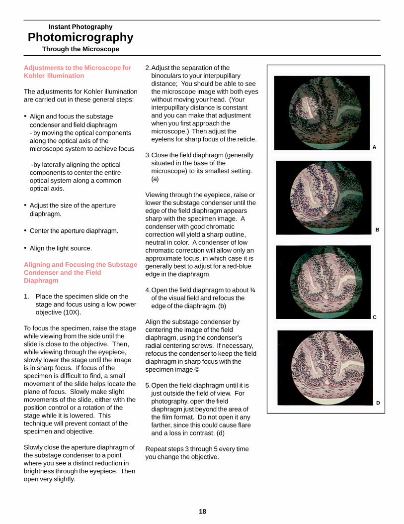
3.Close the field diaphragm (generallysituated in the base of themicroscope) to its smallest setting.(a)
Viewing through the eyepiece, raise orlower the substage condenser until theedge of the field diaphragm appearssharp with the specimen image. Acondenser with good chromaticcorrection will yield a sharp outline,neutral in color. A condenser of lowchromatic correction will allow only anapproximate focus, in which case it isgenerally best to adjust for a red-blueedge in the diaphragm.
4.Open the field diaphragm to about ¾of the visual field and refocus theedge of the diaphragm. (b)
Align the substage condenser bycentering the image of the fielddiaphragm, using the condenser’sradial centering screws. If necessary,refocus the condenser to keep the fielddiaphragm in sharp focus with thespecimen image ©
5.Open the field diaphragm until it isjust outside the field of view. Forphotography, open the fielddiaphragm just beyond the area ofthe film format. Do not open it anyfarther, since this could cause flareand a loss in contrast. (d)
Repeat steps 3 through 5 every timeyou change the objective.
A
B
C
D
Controlling the Size of the ApertureDiaphragm
Set the size if the substage condenseraperture diaphragm to ensure the bestpossible image of the specimen. As arule of thumb, the diaphragm shouldbe closed down sufficiently to providethe desired image contrast, but not sofar as to cause a loss of resolution ofdetail.
The best setting will vary with thenature of the specimen, as well as withthe information or effect that is to bederived from the image. Mostcommonly, the setting will be such thatthe circle of light within the diaphragmblades has a diameter of 2/3 to ¾ thesize of the entire light disc, as seendown the eyepiece tube with theeyepiece removed.
Illustration of aperture diaphragm adjusted todiameter of 2/3 to 3/4 of the entire light disc.
Instant Photography
PhotomicrographyThrough the Microscope
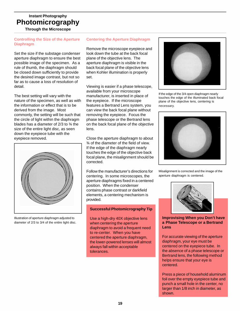
Centering the Aperture Diaphragm
Remove the microscope eyepiece andlook down the tube at the back focalplane of the objective lens. Theaperture diaphragm is visible in theback focal plane of the objective lenswhen Kohler illumination is properlyset.
Viewing is easier if a phase telescope,available from your microscopemanufacturer, is inserted in place ofthe eyepiece. If the microscopefeatures a Bertrand Lens system, youcan view the back focal plane withoutremoving the eyepiece. Focus thephase telescope or the Bertrand lenson the back focal plane of the objectivelens.
Close the aperture diaphragm to about¾ of the diameter of the field of view.If the edge of the diaphragm nearlytouches the edge of the objective backfocal plane, the misalignment should becorrected.
Follow the manufacturer’s directions forcentering. In some microscopes, theaperture diaphragms fixed in a centeredposition. When the condensercontains phase contrast or darkfieldelements, a centering mechanism isprovided.
Successful Photomicrography Tip
Use a high-dry 40X objective lenswhen centering the aperturediaphragm to avoid a frequent needto re-center. When you havecentered the aperture diaphragm,the lower-powered lenses will almostalways fall within acceptabletolerances.
If the edge of the 3/4 open diaphragm nearlytouches the edge of the illuminated back focalplane of the objective lens, centering isnecessary.
Misalignment is corrected and the image of theaperture diaphragm is centered.
Improvising When you Don’t havea Phase Telescope or a BertrandLens
For accurate viewing of the aperturediaphragm, your eye must becentered on the eyepiece tube. Inthe absence of a phase telescope orBertrand lens, the following methodhelps ensure that your eye iscentered.
Press a piece of household aluminumfoil over the empty eyepiece tube andpunch a small hole in the center, nolarger than 1/8 inch in diameter, asshown.
19
Instant Photography
PhotomicrographyThrough the Microscope
20
Manually Aligning the Light Source
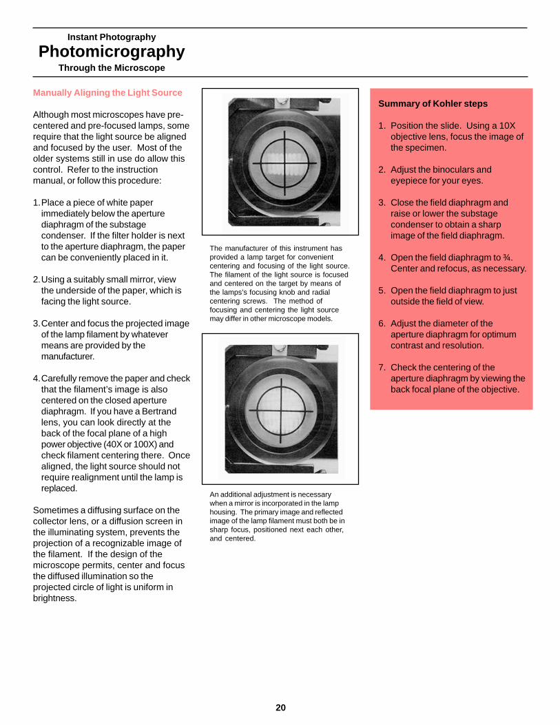
Although most microscopes have pre-centered and pre-focused lamps, somerequire that the light source be alignedand focused by the user. Most of theolder systems still in use do allow thiscontrol. Refer to the instructionmanual, or follow this procedure:
1.Place a piece of white paperimmediately below the aperturediaphragm of the substagecondenser. If the filter holder is nextto the aperture diaphragm, the papercan be conveniently placed in it.
2.Using a suitably small mirror, viewthe underside of the paper, which isfacing the light source.
3.Center and focus the projected imageof the lamp filament by whatevermeans are provided by themanufacturer.
4.Carefully remove the paper and checkthat the filament’s image is alsocentered on the closed aperturediaphragm. If you have a Bertrandlens, you can look directly at theback of the focal plane of a highpower objective (40X or 100X) andcheck filament centering there. Oncealigned, the light source should notrequire realignment until the lamp isreplaced.
Sometimes a diffusing surface on thecollector lens, or a diffusion screen inthe illuminating system, prevents theprojection of a recognizable image ofthe filament. If the design of themicroscope permits, center and focusthe diffused illumination so theprojected circle of light is uniform inbrightness.
Summary of Kohler Steps
Summary of Kohler steps
1. Position the slide. Using a 10Xobjective lens, focus the image ofthe specimen.
2. Adjust the binoculars andeyepiece for your eyes.
3. Close the field diaphragm andraise or lower the substagecondenser to obtain a sharpimage of the field diaphragm.
4. Open the field diaphragm to ¾.Center and refocus, as necessary.
5. Open the field diaphragm to justoutside the field of view.
6. Adjust the diameter of theaperture diaphragm for optimumcontrast and resolution.
7. Check the centering of theaperture diaphragm by viewing theback focal plane of the objective.
The manufacturer of this instrument hasprovided a lamp target for convenientcentering and focusing of the light source.The filament of the light source is focusedand centered on the target by means ofthe lamps’s focusing knob and radialcentering screws. The method offocusing and centering the light sourcemay differ in other microscope models.
An additional adjustment is necessarywhen a mirror is incorporated in the lamphousing. The primary image and reflectedimage of the lamp filament must both be insharp focus, positioned next each other,and centered.

The Condenser’s Illuminating Cone
The illustrations below show how theangle of the illuminating cone, and thusthe numerical aperture of thecondenser, are controlled by theaperture diaphragm of the condenser.
As the aperture of the diaphragm isclosed down, the cone of light becomes
Instant Photography
PhotomicrographyThrough the Microscope
narrower and more sharply delineated(while the lower part of the cone, whichrepresents the specimen plane,remains constant in size).
If the field diaphragm were reduced insize, the lower part of the cone wouldbecome smaller (but the angle of thecone, and thus the numerical aperture,would remain essentially unaltered).
To show the path of light rays emitted from the condenser,a small block of uranium glass, which fluoresces when itabsorbs visible light of short wavelengths, was oiled to thetop of a highly corrected substage condenser.
A typical field of view when the substagecondenser and the field and aperturediaphragms have been set properly. Theaperture diaphragm setting will affect the abilityof the objective lens to resolve fine detail. Itwill also control image contrast and depth offield.
When the conditions of Kohler illuminationhave been met, the partially closed fielddiaphragm will be in focus together with thespecimen. (This requirement is indicated inthe diagram of the image-forming ray path,page 16.)
When the substage condenser is not focusedproperly, a reduction in either field or aperturediaphragm setting produces unevenillumination over the visual field. This effectmay be recorded noticeably on film, even whenit is barely perceptible when viewing throughthe microscope.
Typical Field Views for Kohler Illumination
NA 1.20 NA 0.60 NA 0.30 NA 0.15
21

Instant Photography
PhotomicrographyThrough the Microscope
22
The Reflected Light Microscope
In reflected light microscopes, theobjective also acts as the condenser.The objective both focuses theillumination onto the specimen, andthen images the light reflected fromspecimen. Consequently, setting up forKohler illumination in reflected lightmicroscopes is simpler, and does notrequire positioning of the condenser.The field diaphragm is the apertureclosest to the objective. The aperturediaphragm is further away, but isimaged by a relay lens in the backfocal plane of the objective.
The setting of the field diaphragm has alarge effect on flare in the image andshould be closed down to illuminateonly the area being photographed. Asin transmitted light, the aperturediaphragm controls the cone ofillumination and affects the resolution offine detail.
Successful PhotomicrographyTips
• If you are focusing on a samplethat is nearly featureless, the planeof focus is hard to find. Close thefielddiaphragm to its smallestdiameter and look for the sharpimage of the field diaphragm.Optimum focus of the specimenwill be close to that setting.
• If you need to examine the surfaceof a highly scattering sample, anopaque evaporated metal or carboncoating diminishes the amount oflight scattered from subsurfacefeatures, and increases thecontrast of the image.
• If you need to examine the surfaceof a clear specimen, oil thespecimen toa blackened glassslide. This eliminates reflectionfrom the back surface, increasingcontrast of the image of the frontsurface.
Setting Up Kohler Illumination for aReflected Light Microscope
1.Adjust the binoculars to yourinterocular distance and focus theeyepiece reticle.
2.Place the specimen on the stage,checking to ensure that there is nocoverslip.
3.Center the specimen under a lowpower objective lens (approximately10X).
4.Close the field diaphragm
5.Focus the specimen. It will be infocus when the image of the fielddiaphragm is near focus. Theobjective acts as its own condenserand proper positioning of the fielddiaphragm occurs automatically.
6.Center the field diaphragm and opento the edge of the field of view.
7.Adjust the aperture diaphragm foroptimal contrast and resolution.
Instant Photography
PhotomicrographyThrough the Microscope
Further UnderstandingKohler Illumination
Polaroid
23
Introduction
Proper illumination is the mostimportant feature of photomicrography.The substage condenser’s aperturediaphragm controls the angular cone ofillumination, and thus the amount oflight that reaches the objective lens.The adjustment of the aperturediaphragm is one of the most importantsteps. It has a decisive effect on thecontrast and resolution of the image.Understanding proper techniques forillumination and the function of theaperture diagram is essential for high-quality photomicrography.
Beech, myrtle,grapvine andmaize stems, 2xPolachromeRoland H. Gebert

Instant Photography
PhotomicrographyThrough the Microscope
24
How the Specimen Affects Light
As it encounters the specimen, light isaffected in several ways, dictated bythe characteristics of the specimen. Intransmitted light brightfield microscopy,the three dominant effects areabsorption, refraction, and diffraction.
Absorption
Absorption is the reduction in theintensity of light as it is transmittedthrough a medium. When theabsorption of light is spectrallyselective, the light will change color asit passes through the medium. Certainmicroscope specimens are stained, sothat the selective absorption of light canbe utilized to reveal the greatestpossible detail and information.
Refraction
Refraction is the deflection, orchanging of course, of light rays asthey pass obliquely from one mediumto another of different refractive index(that is, between media in which thevelocity of light is different). The twomedia could be two different specimenparts, or they could be the specimenand the mounting medium.
Diffraction
Diffraction is a deflection of light rays atan “edge” or interface between smalldetails of the specimen having differentabsorptive or refractive properties.Diffracted light plays an important partin the creation of a microscope image.The more diffracted light rays anobjective lens can accept, the better itcan resolve the specimen.
Smaller features in a specimen diffractlight to a greater angle than largefeatures. Red light is diffracted to agreater angle than blue light.
A red filter absorbs blue and green lightand transmits its own color, red.
The path of a single oblique ray.
Diffraction at the edge of a specimen.

Instant Photography
PhotomicrographyThrough the Microscope
Controlling Light and Image Quality
Image quality depends on a subtleinterplay between the objective lensand the substage condenser’s aperturediaphragm.
The Objective lens
The more diffracted light rays anobjective lens can accept, the better itsresolving power. The larger thenumerical aperture of the objective, thegreater its light-gathering power, andthe smaller the features it can resolve.
The substage condenser
The substage condenser supplies thespecimen, as well as the objectivelens, with a concentrated beam of light.The substage condenser also has anumerical aperture. It indicates thecondenser’s light-concentrating ability,or its maximum cone of illumination.When the effective numerical apertureof the substage condenser, ascontrolled by the aperture diaphragm,closely matches the numerical apertureof the objective lens, there is thegreatest potential for resolving detail.As the aperture diaphragm isprogressively closed down, it changesthe proportion of direct image-forminglight to deflected or refracted) lightreaching the objective. The ability toalter this proportion allows somecontrol of image quality.
The Mix of Deflected and DirectLight
The light at the back focal plane of theobjective is a mix of direct rays andrays diffracted or refracted by thespecimen. You can observe the mix ofdirect rays and deflected rays byremoving the microscope eyepiece andviewing the back focal plane of theobjective. An enlarged and moredetailed view will be obtained if theeyepiece is replaced by a phasetelescope, described on page 19.
The angle of the direct light raysreaching the objective lens from thespecimen depends on the setting ofthe aperture diaphragm. As theaperture size is reduced, the centralcircle of direct light decreasesproportionally, while the surrounding
deflected (diffracted and refracted)light is hardly reduced at all.
The central circle of direct illuminatingrays represents light that was affectedby absorption in the specimen. Theless intense light that fills the entireback focal plane of the objective lens isdiffracted and refracted light. Theintensity of this light depends on theamount of diffraction and refractionpresent and thus on the nature of thespecimen. Deflected rays actuallyoccupy the full aperture of the objectivelens. They are not discernible in thecentral illuminating beam simplybecause they are overwhelmed by theintensity of that beam. Deflected lightdoes not represent unwanted flare. It isvery important and useful for forming theimage.
Aperture diaphragm settings and angle of direct light rays reaching objective lens.Left: The aperture diaphragm is almost fully open and the sample is illuminated by awide cone of direct rays. Right: The aperture diaphragm is closed down. The cone ofillumination is smaller and the deflected rays have a greater effect on the image.
25
Instant Photography
PhotomicrographyThrough the Microscope
26
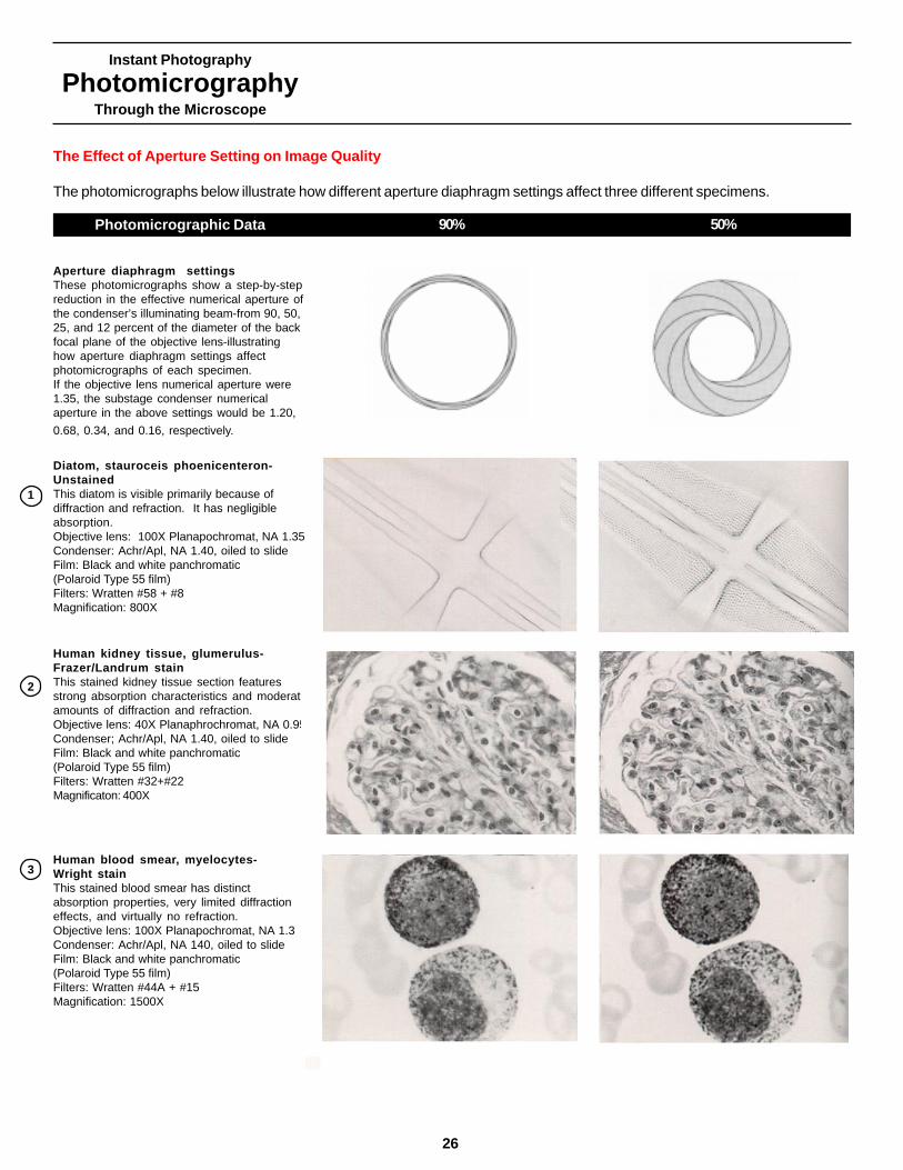
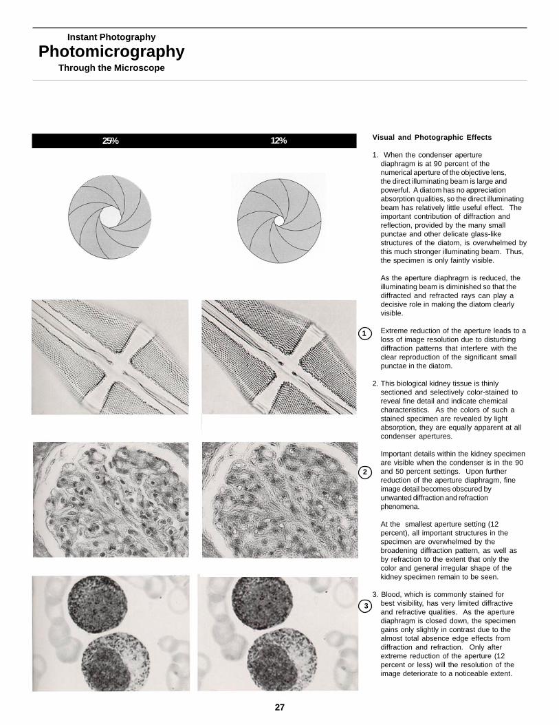
Aperture diaphragm settingsThese photomicrographs show a step-by-stepreduction in the effective numerical aperture ofthe condenser’s illuminating beam-from 90, 50,25, and 12 percent of the diameter of the backfocal plane of the objective lens-illustratinghow aperture diaphragm settings affectphotomicrographs of each specimen.If the objective lens numerical aperture were1.35, the substage condenser numericalaperture in the above settings would be 1.20,
0.68, 0.34, and 0.16, respectively.
The Effect of Aperture Setting on Image Quality
The photomicrographs below illustrate how different aperture diaphragm settings affect three different specimens.
Photomicrographic Data 90% 50%
Diatom, stauroceis phoenicenteron-UnstainedThis diatom is visible primarily because ofdiffraction and refraction. It has negligibleabsorption.Objective lens: 100X Planapochromat, NA 1.35Condenser: Achr/Apl, NA 1.40, oiled to slideFilm: Black and white panchromatic(Polaroid Type 55 film)Filters: Wratten #58 + #8Magnification: 800X
Human kidney tissue, glumerulus-Frazer/Landrum stainThis stained kidney tissue section featuresstrong absorption characteristics and moderateamounts of diffraction and refraction.Objective lens: 40X Planaphrochromat, NA 0.95Condenser; Achr/Apl, NA 1.40, oiled to slideFilm: Black and white panchromatic(Polaroid Type 55 film)Filters: Wratten #32+#22Magnificaton: 400X
Human blood smear, myelocytes-Wright stainThis stained blood smear has distinctabsorption properties, very limited diffractioneffects, and virtually no refraction.Objective lens: 100X Planapochromat, NA 1.35Condenser: Achr/Apl, NA 140, oiled to slideFilm: Black and white panchromatic(Polaroid Type 55 film)Filters: Wratten #44A + #15Magnification: 1500X
1
2
3
Instant Photography
PhotomicrographyThrough the Microscope
25% 12% Visual and Photographic Effects
1. When the condenser aperturediaphragm is at 90 percent of thenumerical aperture of the objective lens,the direct illuminating beam is large andpowerful. A diatom has no appreciationabsorption qualities, so the direct illuminatingbeam has relatively little useful effect. Theimportant contribution of diffraction andreflection, provided by the many smallpunctae and other delicate glass-likestructures of the diatom, is overwhelmed bythis much stronger illuminating beam. Thus,the specimen is only faintly visible.
As the aperture diaphragm is reduced, theilluminating beam is diminished so that thediffracted and refracted rays can play adecisive role in making the diatom clearlyvisible.
Extreme reduction of the aperture leads to aloss of image resolution due to disturbingdiffraction patterns that interfere with theclear reproduction of the significant smallpunctae in the diatom.
2. This biological kidney tissue is thinlysectioned and selectively color-stained toreveal fine detail and indicate chemicalcharacteristics. As the colors of such astained specimen are revealed by lightabsorption, they are equally apparent at allcondenser apertures.
Important details within the kidney specimenare visible when the condenser is in the 90and 50 percent settings. Upon furtherreduction of the aperture diaphragm, fineimage detail becomes obscured byunwanted diffraction and refractionphenomena.
At the smallest aperture setting (12percent), all important structures in thespecimen are overwhelmed by thebroadening diffraction pattern, as well asby refraction to the extent that only thecolor and general irregular shape of thekidney specimen remain to be seen.
3. Blood, which is commonly stained forbest visibility, has very limited diffractiveand refractive qualities. As the aperturediaphragm is closed down, the specimengains only slightly in contrast due to thealmost total absence edge effects fromdiffraction and refraction. Only afterextreme reduction of the aperture (12percent or less) will the resolution of theimage deteriorate to a noticeable extent.
1
2
3
27

Determining the Best ApertureDiaphragm Setting
In General, the aperture diaphragmsetting controls image quality in thefollowing ways:
• When the full numerical aperture ofthe objective lens is used, thepotential for optimum imageresolutions is at its highest, butcontrast is relatively low.
• As the aperture diaphragm is closeddown, image resolution tends todeteriorate, but contrast increases.
Setting the aperture diaphragm, whichprovides the most satisfactory mix ofdirect and deflected light, depends onthe proportions of absorption,diffraction, and refraction in thespecimen. It also depends on theinformation that is sought from thespecimen, and whether resolution ofdetail or image contrast is of primaryimportance. Familiarize yourself withthe specimens, and understand theoptical characteristics each displays.
When the aperture diaphragm is closeddown too far, the deflected light over-powers the direct illuminating rays tothat the diffraction causes visible anddisturbing fringes, bands, or patterns inthe image. Unwanted refractionphenomena can produce apparentstructures in the image that do notrepresent the actual specimen. Thiscan lead to erroneous deductions aboutthe specimen.
Instant Photography
PhotomicrographyThrough the Microscope
If the fully illuminated numericalaperture of the condenser is higherthan that of the objective lens,unwanted flare or stray light is present.Under such conditions the image losescontrast, and the image detail isobscured. Literature on photo-micrography often suggests an“average” aperture setting of about ¾the diameter of the entire disk visiblewhen you look at the back focal planeof the objective. However, this shouldserve only as an approximate setting.The examples in this chapter will helpyou determine the aperture settingmost appropriate for your specimen.
The Aperture Diaphragm and ItsEffect on Depth of Field
Closing the aperture diaphragmincreases the zone of sharpness, ordepth of field, through the thickness ofthe specimen. This is significant withlower power instruments such asstereo zoom microscopes.
Critical Factors that Affect ImageQuality and Resolution forPhotomicrography
• The objective lens numericalaperture.
• The condenser numerical apertureand the setting of its aperturediaphragm.
• The wavelength (color) of the light.
• The nature of the mountingmedium.
• The staining technique.
• The thickness of the sample.
28

Instant Photography
PhotomicrographyThrough the Microscope
Instant Film Characteristicsfor Photomicrography
Polaroid
29
Introduction
A variety of film types and formats areavailable for instant photography. Toselect the best film to record theinformation you need, it’s important tounderstand the special characteristicsof each.
Base the choice between black andwhite or color film on thecharacteristics of the specimen. Forexample, a monochromatic specimen,which inherently has only shades ofgray or a single color, is best recordedin black and white. For stainedspecimens, whose colors are the resultof staining to differentiate structure, useblack and white film and filters todramatically enhance the rendering ofstains and communicate thespecimens’ features most clearly. Forspecimens that are multicolored in theirnatural state, use color film tocommunicate the appearanceaccurately.
Instant films are available in black andwhite print, print with usable negative,positive black and white transparencyand color print or positive transparencyformats. Sizes range from 35mm to8 x 10”.
See-crabcarapace, 25xPolaChromeIgnaz Kaelin
Instant Photography
PhotomicrographyThrough the Microscope
30
Film Instruction Sheets andTechnical Data Sheets
For the most up to date informationon the characteristics of the film youare using, please read the instructionsheet packed with the film.
Technical data sheets are availablefor most films. These contain morecomplete information. They areavailable through the Hotline.
Why There Are No ExposureTables for Photomicrography
It isn’t practicable to provide specificexposure tables for photomicrographybecause there are simply too manyvariables to consider, including:
• Image magnification
• Numerical aperture of the objectivelens
• Nature of the illumination
• Film speed
• Reciprocity failure
• Effects of filtration
• Microscope optics light absorptioncharacteristics
• Nature of the specimen
Film Speed Choices
Film speed, or sensitivity, varies by filmtype. Make your selection of filmspeed according to the specimen’scharacteristics and the available l lightlevel in the instrument. Generally,
• Higher speed films are used in lowerlight levels
• Higher speed films render highercontrast images
• Higher speed films tend to have morestructure or grain
If a specimen is moving or if the lightlevel is low (such as with a fluorescentstain), choose a 3000 speed film, forshortest exposure time.
Successful Photomicrography Tip
The microscope objective is thecomponent that limits the resolutionachieved by the microscope. Ingeneral, the resolution of the film andthe microscope optics are wellmatched with a 10X to 15X eyepieceand a camera with a 1X magnificationfactor. When choosing thephotographic magnification,remember the general rule forMaximum Useful Magnification(MUM): 1000 x NA of the objective.Magnification higher than that isempty magnification and will notproduce further detail. The maximumuseful magnification for a 10Xobjective with a 0.3 NA is 300X. Themaximum for a 100X with 1.3 NAobjective is 1,300X.
Photographic Image Resolution
Resolution is expressed as the numberof line pairs per millimeter which thefilm can resolve. (The resolution ofeach film is listed on the chart at theback of this book.) For generalrecording, any instant film has sufficientresolution to capture the detail presentin a microscope image. High-qualitypublication illustrations or presentationtransparencies of detailed specimensrequire the higher resolution of peel-apart films.
Among the highest resolution filmsavailable for either instant orconventional photography are thenegatives of the Polaroid positive/negative films. Polaroid offers Types665, 55, and 51HC film for applicationsthat require further enlargement ormultiple copies.
Polapan and Polagraph HC instant35mm films have a resolution of 90 linepairs per millimeter and may also beused for enlargements.
Contrast
Polaroid black and white print films areall medium contrast, with the exceptionof high contrast Type 51HC.
The contrast of the print films can beslightly increased by extendingprocessing time to up to double itssuggested time.
You will have greatest control ofcontrast by using Kohler illuminationand by the filtration techniques andcontrast enhancement techniquesdiscussed in later chapters.

Instant Photography
PhotomicrographyThrough the Microscope
Polacolor 64 Tungsten,balanced for tungstenlight, requires little orfiltration forphotomicrography.
Polacolor ER, balanced fordaylight, gives a red-yellowimage if no filtration is used.
When a Wratten 80 Serieslight balancing filter is usedto correct color renditionwith Polacolor ER film, thecolor balance is more
neutral.
Successful Photomicrography Tips
• Polacolor 64 Tungsten film requiresno filtration at exposures between1/8 second and eight seconds. Ifthe light is bright and exposuretime is less than 1/8 second, addneutral density filters to increasethe exposure time.
• Similarly, Polacolor ER filmrequires no filtration atapproximately four seconds.If you use Polacolor ERfilm with tungsten lighting, useneutral density filters to increasethe exposure time to four seconds.
• Automatic exposure systemscannot correct for color shifts duetoreciprocity failure, even with builtin exposure corrections. However,the MicroCam contains a blue lightbalancing filter to balance the colortemperature over a range ofexposures.
Color Temperature
Most microscopes use tungsten ortungsten/halogen light sources. Filmsbalanced for tungsten/halogen lighting,having color temperature of 3200degrees Kelvin (3200K), usually providethe most accurate renderings forphotomicrographs. Polaroid offersPolacolor 64 Tungsten instant print filmin 3 ¼ x 4 ¼” pack and 4 x 5” sheetformats.
Daylight films are designed to be usedwith daylight or electronic flash(5500oK); filtration is needed forphotomicrography. When you usetungsten or tungsten/halogen lightingwith daylight film, you may get a morered/yellow photomicrograph image thanthe specimen appears through themicroscope.
Xenon arc lamps and cesium iodidelamps have outputs similar tophotographic daylight. Polaroidrecommends Polacolor ER film,available in all formats except 35mm,for these light sources.
Polachrome and Polachrome HC 35mmfilms are also balanced for daylight.They require light-balancing filters whenyou use tungsten or tungsten/halogenlamps.
31
Instant Photography
PhotomicrographyThrough the Microscope
32
Spectral Sensitivity of Instant Film
Silver halides are inherently sensitive inthe blue and ultraviolet regions of thespectrum. Sensitizing dyes are addedto extend their sensitivity to longerwavelengths. The absorption peaks ofthe sensitizing dyes cause the peaksin the sensitivity curve.
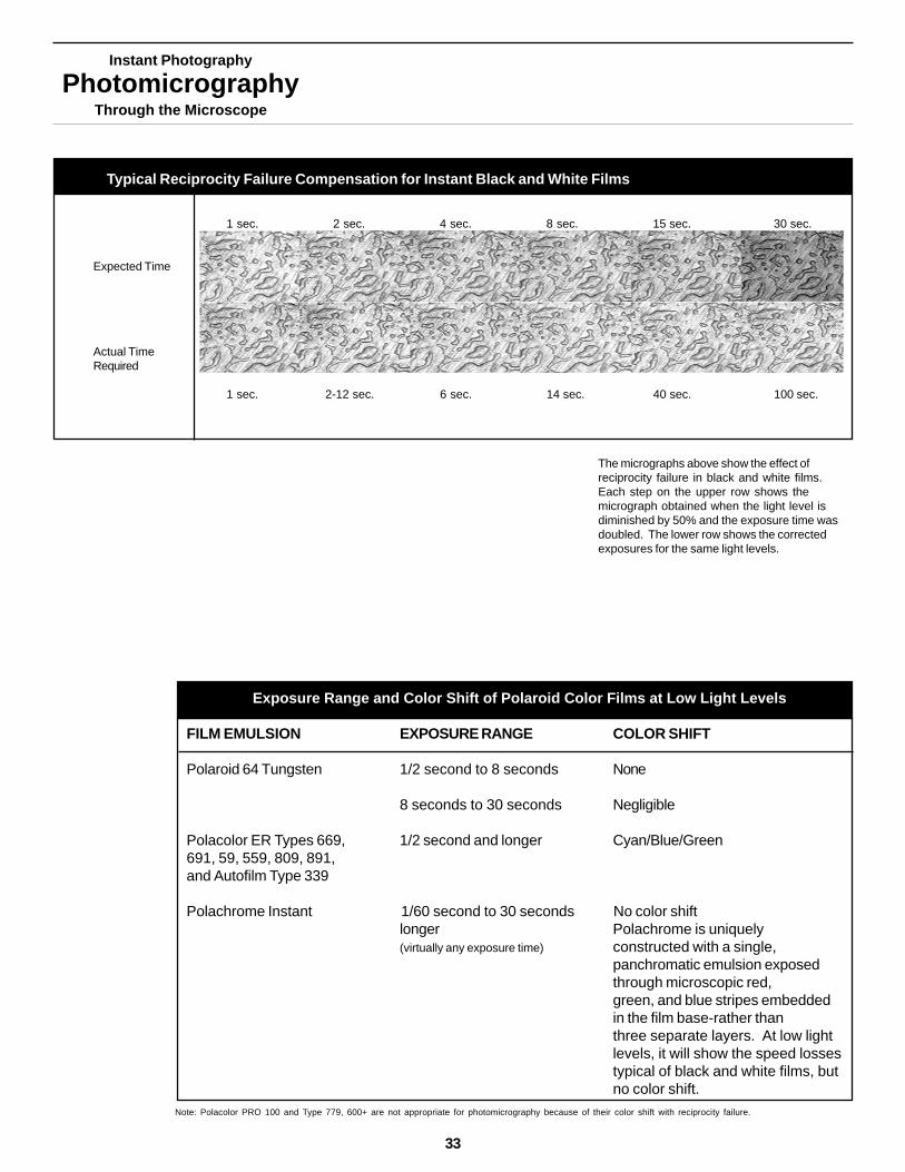
Reciprocity Failure in Black andWhite Films
For general photography using instantand conventional film, the reciprocitylaw states that the total exposure offilm relates directly to the total lightenergy it absorbs. Exposure is theproduct of the exposure time and lightintensity.
If the light intensity is halved, and theexposure time is doubled, the filmresponse should remain the same.This response law does not hold true atlow light levels. Reciprocity failure, orthe failure of the reciprocity law, is acommon phenomenon inphotomicrography, where low lightlevels are frequently encountered.
The sensitivity of instant black andwhite film decreases at exposure timeslonger than one or two seconds. Theexpected exposure time for a highquality image as measured by a lightmetering system or calculatedmathematically yields increasinglyunderexposed images as lightintensities decrease. For black andwhite film, the exposure time should beincreased as shown on the followingpage.
Reciprocity Failure in Color Films
Most color films form images bycombining three separate emulsionlayers that are sensitive to red, greenand blue light. Color films havereciprocity failure at low light levels withone additional complication-the threelayers lose sensitivity at different rates,creating a change in color rendition.Color shifts progress in intensity withdecreasing light levels. Thus, with longexposure times, the decrease in filmspeed due to a reciprocity failure isaccompanied by a shift in apparentcolor balance. When using Polacolorfilms balanced for daylight, the shift canbe corrected by diminishing the amountof blue filtration.
Successful Photomicrography Tip
Many camera systems have built-incorrections for reciprocity failure.They automatically increase theexposure time sensed by the meterto compensate for loss of filmsensitivity with long exposures.
This graph shows the sensitivity curve ofPolacolor 64 Tungsten film. The curvesillustrate the spectral sensitivities of each ofthe three emulsion layers in the negative. Theoverlaps of sensitivities can affect therendition of very narrow band illumination,such as light from sodium arc lamps.
A graph showing the spectral sensitivity ofPolaroid Type 52 film, typical of the sensitivitiesof most Polaroid black and white films. Theemulsion has maximum sensitivity in the 400 to450 nanometer range with further sensitivitypeaks near 550 and 630 nanometers. Thespectral sensitivity diminishes rapidly atwavelengths above 650 nanometers.
Instant Photography
PhotomicrographyThrough the Microscope
The micrographs above show the effect ofreciprocity failure in black and white films.Each step on the upper row shows themicrograph obtained when the light level isdiminished by 50% and the exposure time wasdoubled. The lower row shows the correctedexposures for the same light levels.
Exposure Range and Color Shift of Polaroid Color Films at Low Light Levels
Exposure Range and Color Shift of Polaroid Color Films at Low Light Levels
FILM EMULSION EXPOSURE RANGE COLOR SHIFT
Polaroid 64 Tungsten 1/2 second to 8 seconds None
8 seconds to 30 seconds Negligible
Polacolor ER Types 669, 1/2 second and longer Cyan/Blue/Green691, 59, 559, 809, 891,and Autofilm Type 339
Polachrome Instant 1/60 second to 30 seconds No color shiftlonger Polachrome is uniquely(virtually any exposure time) constructed with a single,
panchromatic emulsion exposedthrough microscopic red,green, and blue stripes embeddedin the film base-rather thanthree separate layers. At low lightlevels, it will show the speed lossestypical of black and white films, butno color shift.
Typical Reciprocity Failure Compensation for Instant Black and White Films
1 sec. 2 sec. 4 sec. 8 sec. 15 sec. 30 sec.
Expected Time
Actual TimeRequired
1 sec. 2-12 sec. 6 sec. 14 sec. 40 sec. 100 sec.
Note: Polacolor PRO 100 and Type 779, 600+ are not appropriate for photomicrography because of their color shift with reciprocity failure.
33
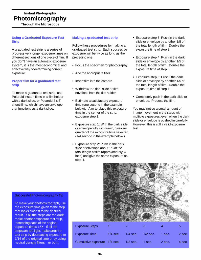
Instant Photography
PhotomicrographyThrough the Microscope
34
Using a Graduated Exposure TestStrip
A graduated test strip is a series ofprogressively longer exposure times ondifferent sections of one piece of film. Ifyou don’t have an automatic exposuresystem, it is the most economical andeffective way of determining correctexposure.
Proper film for a graduated teststrip
To make a graduated test strip, usePolaroid instant films in a film holderwith a dark slide, or Polaroid 4 x 5”sheet films, which have an envelopethat functions as a dark slide.
Successful Photomicrography Tip
To make your photomicrograph, usethe exposure time given to the stepthat looks closest to the desiredresult. If all the steps are too dark,make another exposure test strip,increasing each of the originalexposure times 16X. If all thesteps are too light, make anothertest strip by decreasing exposure to1/16 of the original time or by usingneutral density filters – or both.
Making a graduated test strip
Follow these procedures for making agraduated test strip. Each successiveexposure will be twice as long as thepreceding one.
• Focus the specimen for photography.
• Add the appropriate filter.
• Insert film into the camera.
• Withdraw the dark slide or filmenvelope from the film holder.
• Estimate a satisfactory exposuretime (one second in the examplebelow). Aim to place this exposuretime in the center of the strip,exposure step 3.
• Exposure step 1: With the dark slideor envelope fully withdrawn, give onequarter of the exposure time selected(1/4 second in the example below.)
• Exposure step 2: Push in the darkslide or envelope about 1/5 of thetotal length of film (approximately ¾inch) and give the same exposure asstep 1.
• Exposure step 3: Push in the darkslide or envelope by another 1/5 ofthe total length of film. Double theexposure time of step 2:
• Exposure step 4: Push in the darkslide or envelope by another 1/5 ofthe total length of film. Double theexposure time of step 3.
• Exposure step 5: Push I the darkslide or envelope by another 1/5 ofthe total length of film. Double theexposure time of step 4.
• Completely push in the dark slide orenvelope. Process the film.
You may notice a small amount ofimage movement in the steps withmultiple exposures, even when the darkslide or envelope is pushed in carefully.However, this is still a valid exposuretest.
Exposure Steps 1 2 3 4 5
Exposure Time 1/4 sec. 1/4 sec. 1/2 sec. 1 sec. 2 sec.
Cumulative exposure 1/4 sec. 1/2 sec. 1 sec. 2 sec. 4 sec.

Instant Photography
PhotomicrographyThrough the Microscope
Using Filters for Black andWhite Photomicrography
Polaroid
35
Introduction
Color filters are essential for producinghigh-quality black and whitephotomicrographs. There are two majorreasons to use color filters in black andwhite photomicrography – to controlcontrast in a colored specimen and toconfine the illumination to the part ofthe color spectrum for which themicroscope lens has been optimized.
Filtration techniques used with blackand white film are distinctly differentfrom those designed for colorphotography,. This chapter outlinesfiltration techniques that allow you toproduce top-qualilty black and whiteinstant photomicrographs.
Cupric oxide thinfilm, 50xPolaroid type 52Darell Schlom,James Harris,Jim Eckstein, &Ivan Bozovic
Instant Photography
PhotomicrographyThrough the Microscope
36
Successful Photomicrography Tip
If you place your filters where lightexists from the microscope base,ensure that they are clean andundamaged. Proximity to the fielddiaphragm increases the likelihoodthat a filter’s blemishes will befocused in the plane of the specimenwith the field diaphragm blades.
Where to Obtain Filters
Filters are available from professionalphotographic dealers or microscopemanufacturers or suppliers. Theycome in many sizes, suitable fordifferent microscopes, and in manyformats, such as glass mounts forfrequent use or gelatin squares ofvarious densities. The Kodak Wrattenfilter series, described in thispublication, is indexed with a standardnumbering system. You can referenceequivalent filters from othermanufacturers using this establishedsystem.
Placing Filters in Your Microscope
Place Filters in Your MicroscopePlace your filter in the filter holder, if afilter holder is available. (a)
Or, place the filter where light exits fromthe microscope base. (b)
Understanding Filter Factors
Filter Factors indicate the approximateamount by which an exposure timemust be multiplied in order tocompensate for light absorption by thefilter. Filter factors provide only a roughguide for photomicrography. Manyother factors can influence the filter’seffect on exposure: the spectralsensitivity of the film, color temperatureof the light source, the nature of thespecimen and stain, and the preciseeffect desired in the photomicrograph.
On an automatic exposure system, themeter reading is made through the filterand the exposure time is automaticallylengthened. In theory, you do not needto apply a filter factor. In practice,however, the automatic exposureincrease may not be accurate becauseof differences between the spectralsensitivities of the photocell and thefilm. In such a case, you will need toadjust the exposure manually.
Experiment
Filter Factor Experiment
Determine the length of exposure inwhite light. Then add your chosenfilter to the light path and determinethe new indicated exposure time. Ifthe increase in time is not similar tothe filter factor (listed on the nextpage), adjust the camera manuallyto obtain that time.

Instant Photography
PhotomicrographyThrough the Microscope
Filtration for Optimum ImageResolution
For black and white photomicrographs,filtration can also help you attain thebest possible resolution of fine detail.
Objective lenses are not equally wellcorrected for optical aberrations overthe entire spectrum. Using only thepart of the spectrum where the lensesare best corrected, you can obtain thefinest possible image quality.
Achromatic lenses have their bestcorrection in the green region of thespectrum. Illumination which isexclusively in this region can beattained by using green filters of a fairlynarrow band, such as a Wratten No.58. Using a No. 58 in conjunction witha No. 15 (deep yellow), yields an evennarrower spectral band of transmission.The examples to the right demonstratethe superior resolution achieved byusing this combination of filters tophotograph carbon black (animal bone).A No. 99 (green) filter would limit thespectral transmission to an evennarrower band.
Apochromatic lenses correctaberrations over a wider range of thespectrum. Green filtration is stillsuitable, however, narrow bandtransmission is not necessary.
Filtration can contribute to imageresolution in another way, too. Thepotential for high resolution of detailincreases as the wavelength of lightdecreases. (Blue light will yield higherresolution than red light.) Thus, a greenNo. 58 filter can contribute to imageresolution simply by eliminating thelong-wavelength red component fromthe illumination. The No. 47B (blue)filter will do so to an even greater extentbecause it transmits shorter wavelengthlight.
This technique can be used only withblack and white film, since illuminationfor color photomicrography must have afull and fairly uniform color spectrum.
Empirical Filter Factors for Selected Wratten Filters
Filter Number Filter Color Filter Factor
These empirical filter 8 Yellow 1.5Xfactors were determined 12 Deep yellow 2Xfrom tests made with 15 Deep yellow 2XWratten filters, black and 22 Deep Orange 2.5Xwhite film (Polaroid 25 Red 3XType 52), and tungsten 29 Deep red 7.5Xlighting. They apply to 34A Magenta 6Xall Polaroid black and 44A Cyan 15Xwhite films with tungsten 47 Blue 15Xor halogen lighting. 47A Light Blue10X
47B Deep Blue 20X
58 Green 10X
Carbon black (animal bone), 1250x.Photomicrographs made with a100x planachromatic objective lensand an achromatic-aplanaticcondenser, using 3000K tungstenillumination.Top: Without filtrationBottom: No. 58 and No. 12 filters.
37

Using Filters for Contrast Control
In a black and white photograph, thecolors of a specimen are translated intoshades of gray. Color filters selectivelytransmit or absorb the colorstransmitted by the specimen. Theyaffect the shades of gray in which thespecimen colors are reproduced. Ingeneral, each filter or filter combinationtransmits light of its own color andabsorbs light of all other colors.
You can enhance the contrast of alight-colored feature in a specimenagainst the right background bydarkening that feature. Also, you cancontrol contrast by rendering the grayof one specimen part distinctly lighteror darker than that of another specimenpart.
In order to decisively suppress somecolors and enhance others, contrastcontrol filters must transmit light withina relatively narrow band of thespectrum. For this reason, these filtersdiffer significantly from those used incolor photomicrography.
Basic Filter Colors for DarkeningColored Specimens
SPECIMEN COLOR TO CONTRAST FILTERBE DARKENED COLOR
Blue RedBlue/Green RedGreen Magenta (Blue/Red)Yellow BlueBrown BlueRed Cyan (Blue/Green)Magenta (Blue/Red) GreenViolet Yellow
Instant Photography
PhotomicrographyThrough the Microscope
38

Instant Photography
PhotomicrographyThrough the Microscope
Selecting Filters for ContrastControl
• To make a specimen stand out moreclearly from a bright background,render the specimen darker by usinga filter of the opposite, orcomplementary, color.
• To enhance contrast and detail in aspecimen made up of two colors, usefiltration to darken the part of thespecimen that contains the mostimportant information. The exactamount the colors should bedarkened and lightened respectivelymust be determined byexperimentation.
• To enhance detail in a stainedspecimen which is very pale, choosea filter of the opposite, orcomplementary color, which willdarken the specimen and enhancedetail.
• To enhance detail in specimen with avery dense stain, choose a filter ofthe same color.
Techniques for contrast control
Good contrast control depends on morethan just selecting an appropriate filtercolor. You must determine which partof the specimen you want to darken,and by how much. Too much contrastcan defeat your purpose, which willgenerally be to record the greatest
possible amount of specimeninformation or image detail. You candetermine the filtration visually, eitherby viewing through the microscope withthe appropriate filter, or filters, in thelight path or by comparing the filtertransmission and stain absorptioncharacteristics.
Tissue and cellscross section
Tissue crosssection
Lightly stained
Puccinia
39
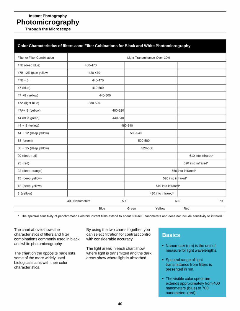
Instant Photography
PhotomicrographyThrough the Microscope
40
The chart above shows thecharacteristics of filters and filtercombinations commonly used in blackand white photomicrography.
The chart on the opposite page listssome of the more widely usedbiological stains with their colorcharacteristics.
By using the two charts together, youcan select filtration for contrast controlwith considerable accuracy.
The light areas in each chart showwhere light is transmitted and the darkareas show where light is absorbed.
Basics
• Nanometer (nm) is the unit ofmeasure for light wavelengths.
• Spectral range of lighttransmittance from filters ispresented in nm.
• The visible color spectrumextends approximately from 400nanometers (blue) to 700nanometers (red).
Color Characteristics of filters aand Filter Cobinations for Black and White Photomicrography
Filter or Filter Combination Light Transmittance Over 10%
47B (deep blue) 400-470
47B +2E (pale yellow 420-470
47B + 3 440-470
47 (blue) 410-500
47 +8 (yellow) 440-500
47A (light blue) 380-520
47A+ 8 (yellow) 480-520
44 (blue green) 440-540
44 + 8 (yellow) 480-540
44 + 12 (deep yellow) 500-540
58 (green) 500-580
58 + 15 (deep yellow) 520-580
29 (deep red) 610 into infrared*
25 (red) 590 into infrared*
22 (deep orange) 560 into infrared*
15 (deep yellow) 520 into infrared*
12 (deep yellow) 510 into infrared*
8 (yellow) 480 into infrared*
400 Nanometers 500 600 700
Blue Green Yellow Red
* The spectral sensitivity of panchromatic Polaroid instant films extend to about 660-690 nanometers and does not include sensitivity to infrared.
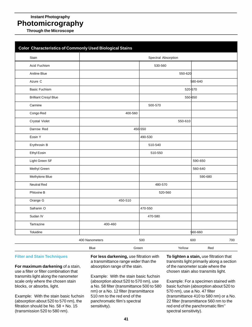
Instant Photography
PhotomicrographyThrough the Microscope
Filter and Stain Techniques
For maximum darkening of a stain,use a filter or filter combination thattransmits light along the nanometerscale only where the chosen stainblocks, or absorbs, light.
Example: With the stain basic fuchsin(absorption about 520 to 570 nm), thefiltration should be No. 58 + No. 15(transmission 520 to 580 nm).
For less darkening, use filtration witha transmittance range wider than theabsorption range of the stain.
Example: With the stain basic fuchsin(absorption about 520 to 570 nm), usea No. 58 filter (transmittance 500 to 580nm) or a No. 12 filter (transmittance510 nm to the red end of thepanchromatic film’s spectralsensitivity).
To lighten a stain, use filtration thattransmits light primarily along a sectionof the nanometer scale where thechosen stain also transmits light.
Example: For a specimen stained withbasic fuchsin (absorption about 520 to570 nm), use a No. 47 filter(transmittance 410 to 580 nm) or a No.22 filter (transmittance 560 nm to thered end of the panchromatic film’’spectral sensitivity).
Color Characteristics of Commonly Used Biological Stains
Stain Spectral Absorption
Acid Fuchism 530-560
Aniline Blue 550-620
Azure C 580-640
Basic Fuchism 520-570
Brilliant Cresyl Blue 550-650
Carmine 500-570
Congo Red 400-560
Crystal Violet 550-610
Darrow Red 450-550
Eosin Y 490-530
Erythrosin B 510-540
Ethyl Eosin 510-550
Light Green SF 590-650
Methyl Green 560-640
Methylene Blue 590-680
Neutral Red 480-570
Phloxine B 520-560
Orange G 450-510
Safranin O 470-550
Sudan lV 470-580
Tartrazine 400-460
Toluidine 560-660
400 Nanometers 500 600 700
Blue Green Yellow Red
41

Instant Photography
PhotomicrographyThrough the Microscope
42
Using Neutral Density Filters
The intensity of the illumination at theeyepiece or film plane can vary greatlywith image magnification or otheroptical factors. Neutral density filters,which are gay or colorless, reduce theintensity of the illumination in a precisemanner. They help to keep exposuretimes as constant as possible or toprovide for more comfortable viewing.
Neutral density filters provide anexcellent alternative to adjusting thelight intensity through the lamp’svoltage control. Variations in lampvoltage will change the colortemperature of the light and makestandardization of filtration difficult.With tungsten or halogen lamps, anexcessive reduction in voltage alsoprevents the lamp from functioningproperly.
At high magnification and with slowerblack and white film, you may need thetotal output of the light source in orderto make a reasonably short exposure.In such a case, you may still want toreduce the intensity of the light forviewing purposes. If you use neutraldensity filters, the visual assessment ofthe effect of a color filter will be moreaccurate than it would be if the lampvoltage were reduced.
Keep a Record of Filter Use
For each filter, keep a record ofphotomicrographic data, includingdetails about the specimen, theobjective and eyepiece, and thetotal photographic magnification.Also list the nature of the illumination,the film type, and the exposure time.
Using Interference Filters
Interference filters, made up of anumber of thin evaporated layers, canalso be used to control contrast.They are designated by:• The center of the wavelength range
they transmit, in nanometers orAngstroms.
• The width of the wavelength rangethey transmit, designated as fwhm,full width of the transmission bandmeasured at the level of one-half themaximum intensity.
Interference filters are available frommicroscope dealers and from opticalcomponent suppliers.
Successful Photomicrography Tip
• A basic set of filters includes 0.10(2) 0.30, 0.60 and 0.90 densities.You can use two filters together, ifnecessary.
For example, 0.30 and 0.90 give atotal density of 1.20 (with atransmittance of about 6 percentof the original illumination). It isadvisable to use no more than twoneutral density filters together.
• Deeply colored filters may slightlydisplace the effective focus of themicroscope, due to opticalcharacteristics of the objectivelens. Check the focus after youput the filter in place – beforemaking the photomicrograph.
Using Heat-Absorbing Filters
A microscope lamp generates infraredradiation, which produces heat that candamage specimens and filters. A heatabsorbing filter is often included asstandard equipment on a microscope.If it is not, insert such a filter into thelight path.
Using Ultraviolet-Absorbing Filters
Black and white films are inherentlysensitive to ultraviolet (UV) radiationwhich is not visible to the human eye.However, in some microscopes it canbe a problem for photography and mayappear as an even haze in aphotomicrograph. Use a Wratten 2A,2B or 2E (or equivalent) filter to absorbthe unwanted UV.
Neutral Density filters and theirLight transmission Characteristics
Neutral Density Percentage ofLight transmitted
0.10 800.20 630.30 500.40 400.50 320.60 250.90 131.00 10

Instant Photography
PhotomicrographyThrough the Microscope
Using Filters for ColorPhotomicrography
Polaroid
43
Introduction
In color photomicrography, filters areused to control the color quality of thelight reaching the film and to achievethe best possible color balance oreffect in your photomicrograph. Thischapter introduces many filters andspecial filtration techniques that cancorrect color imbalances to achieve afull range of desired effects.
PerovskiteIanthanumaluminate, 2.5xPolarized lightPolachrome HCMichael Davidson
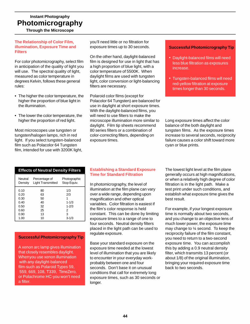
Instant Photography
PhotomicrographyThrough the Microscope
44
The Relationship of Color Film,illumination, Exposure Time andFilters
For color photomicrography, select filmin anticipation of the quality of light youwill use. The spectral quality of light,measured as color temperature indegrees Kelvin, follows these generalrules:
• The higher the color temperature, thehigher the proportion of blue light inthe illumination.
• The lower the color temperature, thehigher the proportion of red light.
Most microscopes use tungsten ortungsten/halogen lamps, rich in redlight. If you select tungsten-balancedfilm such as Polacolor 64 Tungstenfilm, intended for use with 3200K light,
you’ll need little or no filtration forexposure times up to 30 seconds.
On the other hand, daylight-balancedfilm is designed for use in light that hasa high proportion of blue light, with acolor temperature of 5500K. Whendaylight films are used with tungstenlight, color conversion or light-balancingfilters are necessary.
Polaroid color films (except forPolacolor 64 Tungsten) are balanced foruse in daylight at short exposure times.With the daylight-balanced films, youwill need to use filters to make themicroscope illumination more similar todaylight. Film tip sheets recommend80 series filters or a combination ofcolor-correcting filters, depending onexposure times.
Establishing a Standard ExposureTime for Standard Filtration
In photomicrography, the level ofillumination at the film plane can varyover a wide range, depending uponmagnification and other opticalvariables. Color filtration is easiest ifthe film’s color response is heldconstant. This can be done by limitingexposure times to a range of one tofour seconds. Neutral density filtersplaced in the light path can be used toregulate exposure.
Base your standard exposure on theexposure time needed at the lowestlevel of illumination that you are likelyto encounter in your everyday work-probably between one and fourseconds. Don’t base it on unusualconditions that call for extremely longexposure times, such as 30 seconds orlonger.
Long exposure times affect the colorbalance of the both daylight andtungsten films. As the exposure timesincrease to several seconds, reciprocityfailure causes a color shift toward morecyan or blue prints.
The lowest light level at the film planegenerally occurs at high magnifications,or when a relatively high degree of colorfiltration is in the light path. Make atest print under such conditions, andestablish what exposure time gives thebest result.
For example, if your longest exposuretime is normally about two seconds,and you change to an objective lens ofmuch lower power, the exposure timemay change to ¼ second. To keep thereciprocity failure of the film constant,you need to return to a two-secondexposure time. You can accomplishthis by adding a 0.9 neutral densityfilter, which transmits 13 percent (orabout 1/8) of the original illumination,bringing your required exposure timeback to two seconds.
Successful Photomicrography Tip
A xenon arc lamp gives illuminationthat closely resembles daylight.Whenyou use xenon illumination with any daylight-balancedfilm-such as Polaroid Types 59, 559, 669, 108, T339, TimeZero,or Polachrome HC-you won’t needa filter.
Effects of Neutral Density Filters
Neutral Percentage of PhotographicDensity Light Transmitted Stop Equiv.
0.10 80 1/30.20 63 2/30.30 50 10.40 40 1-1/30.50 32 1-2/30.60 25 20.90 13 31.00 10 3-1/3
Successful Photomicrography Tip
• Daylight-balanced films will needless blue filtration as exposuresincrease.
• Tungsten-balanced films will needred-yellow filtration at exposuretimes longer than 30 seconds.

Instant Photography
PhotomicrographyThrough the Microscope
The Effect of Lamp Voltage andExposure Duration on ColorBalance
Before you use filters, ensure the mostconsistent color balance in both theillumination and the response of the filmby:
• Controlling the lamp voltage properly
• Establishing one standard exposuretime for as much of your colorphotomicrography as possible.
Used at the voltage setting specified bythe lamp manufacturer, mostmicroscope tungsten filament lampshave a color temperature ofapproximately 3200K. When youdecrease the voltage, the colortemperature drops and the lightbecomes richer in red rays.
Always use the specified voltagesetting for color photomicrography tominimize the need for filtration and tokeep the color quality of the illuminationconsistent.
Placing Filters in Your Microscope
Place your filter in the filter holder, if afilter holder is available, (a) Or, placethe filter where light exits from themicroscope base. (b)
Successful Photomicrography Tip
If you place your filters where lightexits from the microscope base,ensure that they are clean andundamaged. Proximity to the fileddiaphragm increases the likelihoodthat a filter’s blemishes will befocused in the plane of the specimenwith the field diaphragm blades.
45
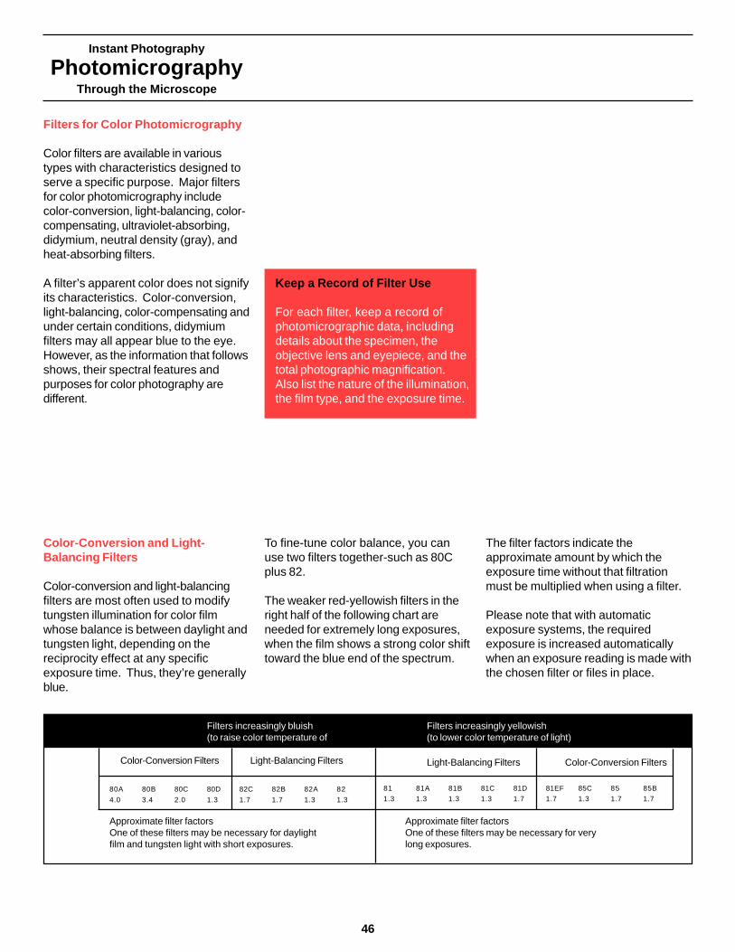
Instant Photography
PhotomicrographyThrough the Microscope
46
Filters for Color Photomicrography
Color filters are available in varioustypes with characteristics designed toserve a specific purpose. Major filtersfor color photomicrography includecolor-conversion, light-balancing, color-compensating, ultraviolet-absorbing,didymium, neutral density (gray), andheat-absorbing filters.
A filter’s apparent color does not signifyits characteristics. Color-conversion,light-balancing, color-compensating andunder certain conditions, didymiumfilters may all appear blue to the eye.However, as the information that followsshows, their spectral features andpurposes for color photography aredifferent.
Color-Conversion and Light-Balancing Filters
Color-conversion and light-balancingfilters are most often used to modifytungsten illumination for color filmwhose balance is between daylight andtungsten light, depending on thereciprocity effect at any specificexposure time. Thus, they’re generallyblue.
Keep a Record of Filter Use
For each filter, keep a record ofphotomicrographic data, includingdetails about the specimen, theobjective lens and eyepiece, and thetotal photographic magnification.Also list the nature of the illumination,the film type, and the exposure time.
To fine-tune color balance, you canuse two filters together-such as 80Cplus 82.
The weaker red-yellowish filters in theright half of the following chart areneeded for extremely long exposures,when the film shows a strong color shifttoward the blue end of the spectrum.
The filter factors indicate theapproximate amount by which theexposure time without that filtrationmust be multiplied when using a filter.
Please note that with automaticexposure systems, the requiredexposure is increased automaticallywhen an exposure reading is made withthe chosen filter or files in place.
Filters increasingly bluish(to raise color temperature of light)
Color-Conversion Filters Light-Balancing Filters
80A 80B 80C 80D 82C 82B 82A 82
4.0 3.4 2.0 1.3 1.7 1.7 1.3 1.3
Approximate filter factorsOne of these filters may be necessary for daylightfilm and tungsten light with short exposures.
Filters increasingly yellowish(to lower color temperature of light)
Light-Balancing Filters Color-Conversion Filters
81 81A 81B 81C 81D 81EF 85C 85 85B
1.3 1.3 1.3 1.3 1.7 1.7 1.3 1.7 1.7
Approximate filter factorsOne of these filters may be necessary for verylong exposures.

Instant Photography
PhotomicrographyThrough the Microscope
Color-conversion filters
Color-conversion filters are designed toconvert the color balance of theillumination to match the color balanceof the film. These filters shift the entirespectral balance either to the cool(blue-cyan) or to the warm (red-yellow)end of the spectrum. They are notintended to control individual colors.
This chart indicates the characteristicsof filters in the 80 (blue) series, whichare used to balance 3200K tungstenlighting for use with daylight-balancedcolor film.
Light-balancing filters
Light-balancing filters are similar tocolor-conversion filters. However, light-balancing filters are weaker. Whenillumination is of the required colortemperature, these filters makepossible additional minor adjustmentsin the color balance of the light.
This chart indicates the characteristicsof filters in the 82 (bluish) series. Thecurves are similar to those of the 80series filters, but less steep.
Color – compensating (CC) filters
Color-compensating filters aredesigned to give you control ofindividual colors in the spectrum, oncethe color temperature of the light hasbeen balanced to match the film’srequirements.
The solid line on this chart ischaracteristic of a CC Green filter,which transmits relatively more greenlight and less blue and red. The brokenline represents a CC Magenta (blue-red) filter, which transmits relativelymore blue and red light and less green.
Successful Photomicrography Tips
• Polacolor 64 Tungsten film is agood choice for simple colorphotomicrography under tungstenor tungsten/halogen illumination.This film does not require a color-conversion filter, and exposures will be two-to-four times shorter.
• Always use the recommendedlamp voltage setting and keep to astandard exposure time wheneverpossible.
47
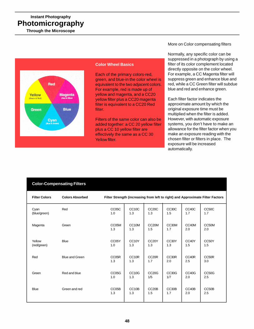
Instant Photography
PhotomicrographyThrough the Microscope
48
More on Color compensating filters
Normally, any specific color can besuppressed in a photograph by using afilter of its color complement locateddirectly opposite on the color wheel.For example, a CC Magenta filter willsuppress green and enhance blue andred, while a CC Green filter will subdueblue and red and enhance green.
Each filter factor indicates theapproximate amount by which theoriginal exposure time must bemultiplied when the filter is added.However, with automatic exposuresystems, you don’t have to make anallowance for the filter factor when youmake an exposure reading with thechosen filter or filters in place. Theexposure will be increasedautomatically.
Color Wheel Basics
Each of the primary colors-red,green, and blue-in the color wheel isequivalent to the two adjacent colors.For example, red is made up ofyellow and magenta, and a CC20yellow filter plus a CC20 magentafilter is equivalent to a CC20 Redfilter.
Filters of the same color can also beadded together: a CC 20 yellow filterplus a CC 10 yellow filter areeffectively the same as a CC 30Yellow filter.
Color-Compensating Filters
Filter Colors Colors Absorbed Filter Strength (increasing from left to right) and Approximate Filter Factors
Cyan Red CC05C CC10C CC20C CC30C CC40C CC50C(blue/green) 1.0 1.3 1.3 1.5 1.7 1.7
Magenta Green CC05M CC10M CC20M CC30M CC40M CC50M1.3 1.3 1.5 1.7 2.0 2.0
Yellow Blue CC05Y CC10Y CC20Y CC30Y CC40Y CC50Y(red/green) 1.0 1.3 1.3 1.3 1.5 1.5
Red Blue and Green CC05R CC10R CC20R CC30R CC40R CC50R1.3 1.3 1.7 2.0 2.5 3.0
Green Red and blue CC05G CC10G CC20G CC30G CC40G CC50G1.0 1.3 1/5 1/7 2.0 2.5
Blue Green and red CC05B CC10B CC20B CC30B CC40B CC50B1.3 1.3 1.5 1.7 2.0 2.5

Instant Photography
PhotomicrographyThrough the Microscope
Color Imbalances
If you have balanced the lighting for thefilm and its reciprocity failure, theimbalance is due to another cause.This chart gives an approximate idea ofthe CC filtration that might be neededunder a variety of conditions.
Successful Photomicrography Tip
Choose the color and strength ofCC filtration you might need tocorrect an imbalance in aphotomicrograph you’ve made.Then view thatphotomicrographthrough the selected filter. Whenthe colors in the photo look wellbalanced-as shown in the right-handcolumn of the chart below-add thatfilter to make the nextphotomicrograph.
Color Imbalances
Color Imbalance Amount CC Filtration Satisfactory(Approximate Range) Color Balance
Too Moderate As illustrated at left 15 to 30 Cyan
Red Slight Imbalance just noticeable 05 to 10 Cyan
Too Moderate As illustrated at left 15 to 30 Magenta
Green Slight Imbalance just noticeable 05 to 10 Magenta
Too Moderate As illustrated at left 15 to 30 Yellow
Blue Slight Imbalance just noticeable 05 to 10 Yellow
Too Moderate As illustrated at left 15 to 30 Red
Cyan Slight Imbalance just noticeable 05 to 10 Red
Too Moderate As illustrated at left 15 to 30 GreenMagenta
Slight Imbalance just noticeable 05 to 10 Green
Too Moderate As illustrated at left 15 to 30 BlueYellow
Slight Imbalance just noticeable 05 to 10 Blue
49
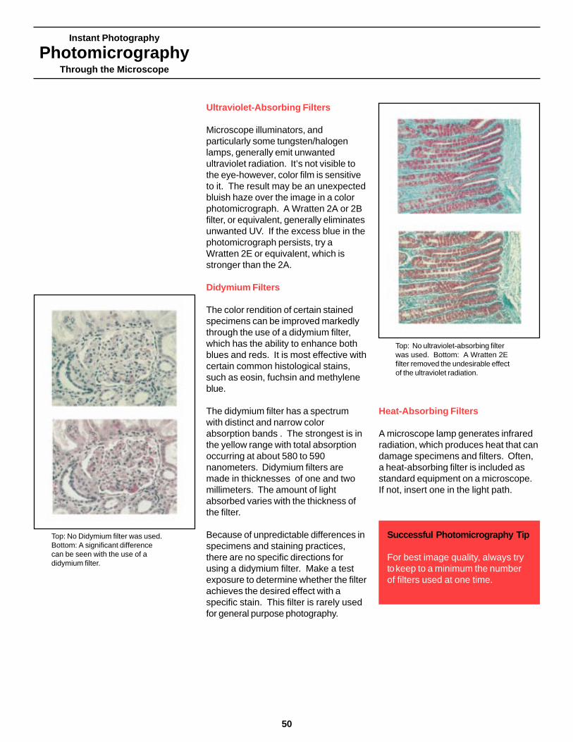
Instant Photography
PhotomicrographyThrough the Microscope
50
Ultraviolet-Absorbing Filters
Microscope illuminators, andparticularly some tungsten/halogenlamps, generally emit unwantedultraviolet radiation. It’s not visible tothe eye-however, color film is sensitiveto it. The result may be an unexpectedbluish haze over the image in a colorphotomicrograph. A Wratten 2A or 2Bfilter, or equivalent, generally eliminatesunwanted UV. If the excess blue in thephotomicrograph persists, try aWratten 2E or equivalent, which isstronger than the 2A.
Didymium Filters
The color rendition of certain stainedspecimens can be improved markedlythrough the use of a didymium filter,which has the ability to enhance bothblues and reds. It is most effective withcertain common histological stains,such as eosin, fuchsin and methyleneblue.
The didymium filter has a spectrumwith distinct and narrow colorabsorption bands . The strongest is inthe yellow range with total absorptionoccurring at about 580 to 590nanometers. Didymium filters aremade in thicknesses of one and twomillimeters. The amount of lightabsorbed varies with the thickness ofthe filter.
Because of unpredictable differences inspecimens and staining practices,there are no specific directions forusing a didymium filter. Make a testexposure to determine whether the filterachieves the desired effect with aspecific stain. This filter is rarely usedfor general purpose photography.
Heat-Absorbing Filters
A microscope lamp generates infraredradiation, which produces heat that candamage specimens and filters. Often,a heat-absorbing filter is included asstandard equipment on a microscope.If not, insert one in the light path.
Successful Photomicrography Tip
For best image quality, always trytokeep to a minimum the numberof filters used at one time.
Top: No Didymium filter was used.Bottom: A significant differencecan be seen with the use of adidymium filter.
Top: No ultraviolet-absorbing filterwas used. Bottom: A Wratten 2Efilter removed the undesirable effectof the ultraviolet radiation.
Instant Photography
PhotomicrographyThrough the Microscope
Neutral Density Filters
Neutral density filters are gray, orcolorless. They reduce light intensitywithout changing the colorcharacteristics of the light, and bycontrolling light intensity they helpcontrol exposure time and colorbalance in a predictable manner.Neutral density filters are available in awide range of densities. For example,Kodak Wratten neutral density filter No.96 is available in 3 inch (75 mm) orlarger gelatin filter squares. Inconelcoated filters on a glass base exhibitbest color neutrality. They are availablefrom microscope dealers or opticalsupply houses.
A basic set of neutral density filtersincludes two 0.10 and one each of0.30, 0.60, and 0.90 densities. Youcan use two filters together, ifnecessary. For example, 0.30 and0.90 give a total density of 1.20 (with atransmittance of about 6 percent of theoriginal illumination). For best quality,it is advisable to use no more than twoneutral density filters together.
Successful Photomicrography Tip
It’s very important to evaluate a printfor color quality only when that printhas been exposed accurately.Incorrect exposure can cause acolor imbalance of its own.
Cause of Color Imbalance
Polar color ER color films ar daylight-balanced. As exposure time increasesto several seconds, reciprocity failurein the film causes a blue-cyan colorshift. Up to a specific point, this shiftmakes the film increasingly compatiblewith tungten illumination. The exactfiltration needed to balance theillumination with the film characteristicsdecreases with longer exposure times.For good color balance with little or nofiltration, use Polacolor 64 Tungstenfilm at standard exposure times of 1/2to ten seconds.
The optical components of themicroscope absorb light selectively, sothat the light reaching the film hasdifferent spectral characterics than thelight emitted by the source.
The spectral transmission properties ofsome biological specimen stainsrequire modification to suit thecharacteristics of the color film beingused to enhance the separationbetween certain specimen colors.
A heat-absorbing filter in the opticalsystem can cause a color imbalance.
A Abbe or aplanatic substagecondenser may introduce a sligh colorimbalance to the image area when anobjective lens with a high numericalaperture (aboce 0.65) is used. Tehcolor of this imbalance will change asyou adjust the focus of the condenser.
Two or more of the above.
Filter Type Needed
Use color-conversion filters or light-balancing filters, depending on theamount of imbalance.
Generally use color-compensatingfilters. Occasionally use ligt-balancingfilters.
Use color-compensating filters.Occasionally us a didymium filter.
Use color-compensating filters.
First, keep the color consistent byalways focusing the condenser toachieves the same effect - the colorfringe at the edge of the image of thefield diaphragm blades should alwayslook the same. To correct animbalance, use appropriate light-balancing or color-compensatingfilters.
Use a combination of filter types.
Sources of Color Imbalance and Filter Solutions
51
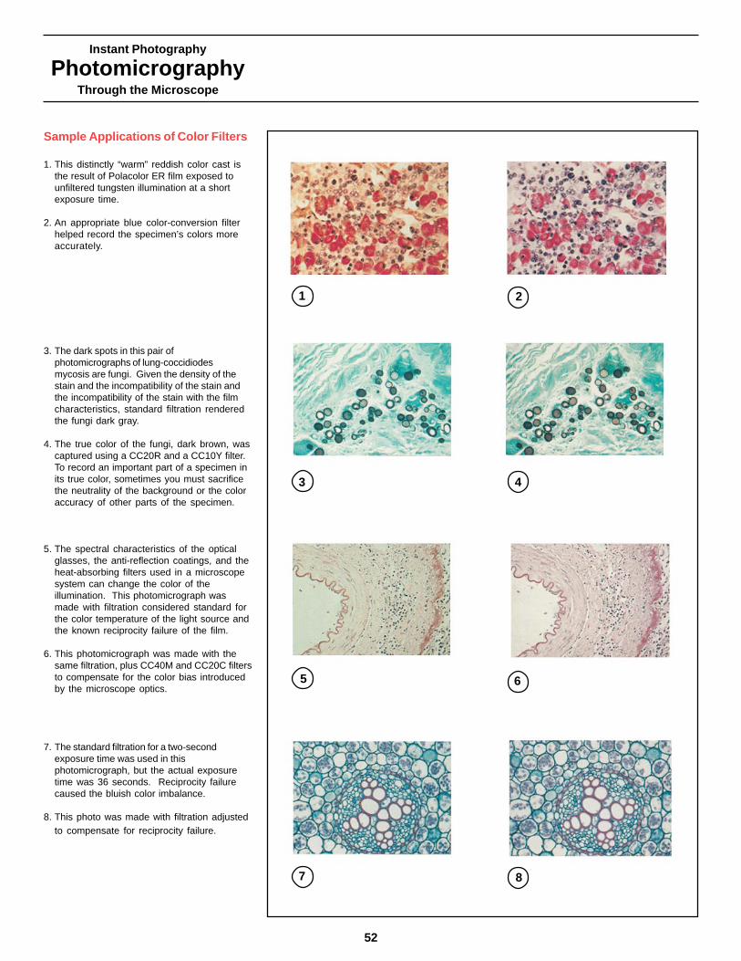
Instant Photography
PhotomicrographyThrough the Microscope
52
Sample Applications of Color Filters
1. This distinctly “warm” reddish color cast isthe result of Polacolor ER film exposed tounfiltered tungsten illumination at a shortexposure time.
2. An appropriate blue color-conversion filterhelped record the specimen’s colors moreaccurately.
3. The dark spots in this pair ofphotomicrographs of lung-coccidiodesmycosis are fungi. Given the density of thestain and the incompatibility of the stain andthe incompatibility of the stain with the filmcharacteristics, standard filtration renderedthe fungi dark gray.
4. The true color of the fungi, dark brown, wascaptured using a CC20R and a CC10Y filter.To record an important part of a specimen inits true color, sometimes you must sacrificethe neutrality of the background or the coloraccuracy of other parts of the specimen.
5. The spectral characteristics of the opticalglasses, the anti-reflection coatings, and theheat-absorbing filters used in a microscopesystem can change the color of theillumination. This photomicrograph wasmade with filtration considered standard forthe color temperature of the light source andthe known reciprocity failure of the film.
6. This photomicrograph was made with thesame filtration, plus CC40M and CC20C filtersto compensate for the color bias introducedby the microscope optics.
7. The standard filtration for a two-secondexposure time was used in thisphotomicrograph, but the actual exposuretime was 36 seconds. Reciprocity failurecaused the bluish color imbalance.
8. This photo was made with filtration adjustedto compensate for reciprocity failure.
1 2
3 4
5 6
7 8

Instant Photography
PhotomicrographyThrough the Microscope
Special Contrast-Enhancement Techniques
Polaroid
53
Introduction
Some specimens are of such lowcontrast that their microscopic image isbarely discernible to either the eye orfilm. A specimen that absorbs almostno light and is virtually colorless callsfor a contrast-enhancement techniquebeyond the use of color filters.
Keep this rule of thumb in mind; aim fora level of contrast that best reveals theinformation you need without sacrificingother important image qualities such asresolution.
You will find the following itemsconvenient for the special contrast-enhancement techniques in thischapter.
High-intensity light source
Contrast-enhancement techniquesmake effective use of only a smallportion of the total illumination.Therefore, you will need a high-intensitylight source and high-speed films tokeep exposure times to a minimum.Read the Kohler Illumination sectionfirst. Properly aligned Kohlerillumination is essential for all specialcontrast-enhancement techniques.
Rotating stage
With some techniques the orientationof the specimen on the stageinfluences the appearance of its image.A rotating stage allows you to controlthe orientation of the sample to suit therequirements of the specific technique.
High-speed film
You need to keep exposure times to aminimum for special contrast-enhancement techniques; therefore,choose high-speed film.
Pine stem,65xPolarized lightRed l PlatePolacolor Type778Mary McCann

Instant Photography
PhotomicrographyThrough the Microscope
54
The Physics of Polarized Light
The polarizer below the specimentransmits light vibrating in one directionand absorbs the remaining light.When the analyzer is crossed with thispolarizer, their transmission directionsare perpendicular to each other. Alllight is absorbed and the image fieldwill appear dark. The isotropic parts ofthe specimen will appear dark, too, asthey will have no effect on the polarizedillumination.
The polarized light that passes througha birefringent area of the specimen issplit into two beams that are polarizedperpendicularly to each other. Thespecimen introduces a phase differencebetween the two beams, depending onits birefringence and thickness. Someof each of these beams will passthrough the analyzer, where theyrecombine and interfere.
The image may appear gray, white, orbrightly colored. Colors and tones aredependent on the interference betweenthe two out-of-phase beams when theyreunite on passing through theanalyzer. The interference colors in theimage indicate the approximatethickness or birefringence in thisspecimen.
Successful Photomicrography Tip
If the microscope does not have abuilt-in location for the analyzer,place the analyzer in the microscopetube or over the eyepiece. If theanalyzer is located where it cannoteasily be rotated, rotate the lowerpolarizer, which can be placed overthe light exit of the microscope.
Polarized Light
Purpose
• To use the birefringence of ananisotropic specimen for pictorial,analytical, or identification purposes.
• To differentiate isotropic specimenareas (those having only one indexof refraction) and anisotropicspecimen areas (those having morethan one index of refraction)
Suitable Specimens
• Chemical crystals• Mineral preparations• Plant and animal tissue• Pharmaceutical preparations• Fats and waxes• Natural and synthetic fibers• Starch grains• Bone and horn sections• Animal and plant hair• Wood sections
Equipment
• One polarizer blow the specimen• One polarizer (called the analyzer)
above the specimen that can berotated at least 90 degrees.
• Strain-free objective lenses andcondensers
• Specimen stage that rotates aboutthe optical axis
• Compensators or retarders (full-waveand quarter-wave plates) forquantitative work and for addingcolor.
Polarized light reveals starch grainsin a cross section of a pelargoniumstem. 160X (left) brightfieldillumination without polarizers;(right) specimen between crossedpolarizers.
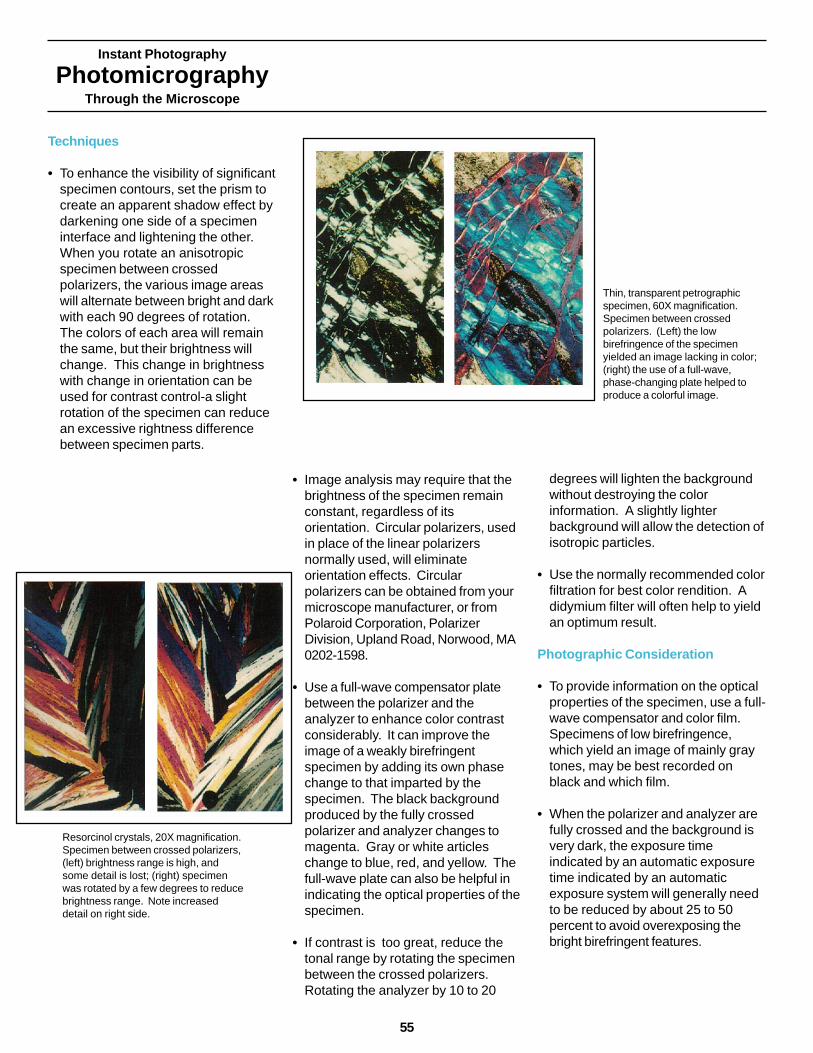
Instant Photography
PhotomicrographyThrough the Microscope
Techniques
• To enhance the visibility of significantspecimen contours, set the prism tocreate an apparent shadow effect bydarkening one side of a specimeninterface and lightening the other.When you rotate an anisotropicspecimen between crossedpolarizers, the various image areaswill alternate between bright and darkwith each 90 degrees of rotation.The colors of each area will remainthe same, but their brightness willchange. This change in brightnesswith change in orientation can beused for contrast control-a slightrotation of the specimen can reducean excessive rightness differencebetween specimen parts.
• Image analysis may require that thebrightness of the specimen remainconstant, regardless of itsorientation. Circular polarizers, usedin place of the linear polarizersnormally used, will eliminateorientation effects. Circularpolarizers can be obtained from yourmicroscope manufacturer, or fromPolaroid Corporation, PolarizerDivision, Upland Road, Norwood, MA0202-1598.
• Use a full-wave compensator platebetween the polarizer and theanalyzer to enhance color contrastconsiderably. It can improve theimage of a weakly birefringentspecimen by adding its own phasechange to that imparted by thespecimen. The black backgroundproduced by the fully crossedpolarizer and analyzer changes tomagenta. Gray or white articleschange to blue, red, and yellow. Thefull-wave plate can also be helpful inindicating the optical properties of thespecimen.
• If contrast is too great, reduce thetonal range by rotating the specimenbetween the crossed polarizers.Rotating the analyzer by 10 to 20
degrees will lighten the backgroundwithout destroying the colorinformation. A slightly lighterbackground will allow the detection ofisotropic particles.
• Use the normally recommended colorfiltration for best color rendition. Adidymium filter will often help to yieldan optimum result.
Photographic Consideration
• To provide information on the opticalproperties of the specimen, use a full-wave compensator and color film.Specimens of low birefringence,which yield an image of mainly graytones, may be best recorded onblack and which film.
• When the polarizer and analyzer arefully crossed and the background isvery dark, the exposure timeindicated by an automatic exposuretime indicated by an automaticexposure system will generally needto be reduced by about 25 to 50percent to avoid overexposing thebright birefringent features.
Resorcinol crystals, 20X magnification.Specimen between crossed polarizers,(left) brightness range is high, andsome detail is lost; (right) specimenwas rotated by a few degrees to reducebrightness range. Note increaseddetail on right side.
Thin, transparent petrographicspecimen, 60X magnification.Specimen between crossedpolarizers. (Left) the lowbirefringence of the specimenyielded an image lacking in color;(right) the use of a full-wave,phase-changing plate helped toproduce a colorful image.
55
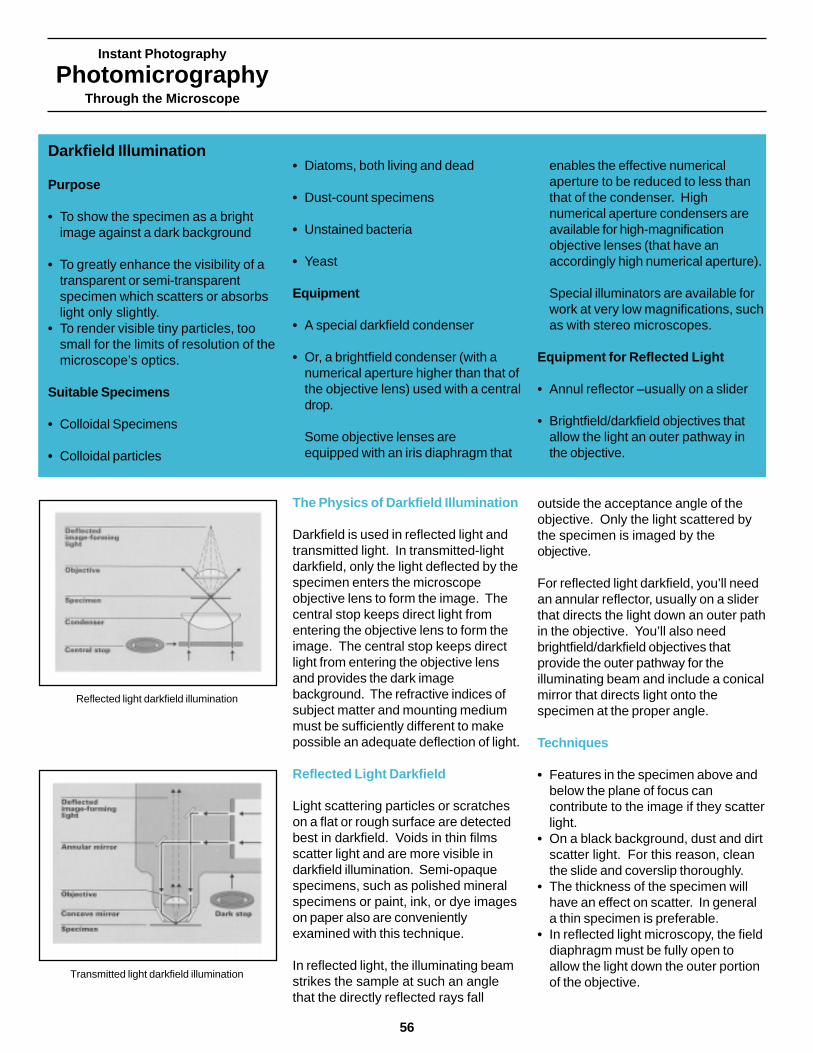
Instant Photography
PhotomicrographyThrough the Microscope
56
The Physics of Darkfield Illumination
Darkfield is used in reflected light andtransmitted light. In transmitted-lightdarkfield, only the light deflected by thespecimen enters the microscopeobjective lens to form the image. Thecentral stop keeps direct light fromentering the objective lens to form theimage. The central stop keeps directlight from entering the objective lensand provides the dark imagebackground. The refractive indices ofsubject matter and mounting mediummust be sufficiently different to makepossible an adequate deflection of light.
Reflected Light Darkfield
Light scattering particles or scratcheson a flat or rough surface are detectedbest in darkfield. Voids in thin filmsscatter light and are more visible indarkfield illumination. Semi-opaquespecimens, such as polished mineralspecimens or paint, ink, or dye imageson paper also are convenientlyexamined with this technique.
In reflected light, the illuminating beamstrikes the sample at such an anglethat the directly reflected rays fall
outside the acceptance angle of theobjective. Only the light scattered bythe specimen is imaged by theobjective.
For reflected light darkfield, you’ll needan annular reflector, usually on a sliderthat directs the light down an outer pathin the objective. You’ll also needbrightfield/darkfield objectives thatprovide the outer pathway for theilluminating beam and include a conicalmirror that directs light onto thespecimen at the proper angle.
Techniques
• Features in the specimen above andbelow the plane of focus cancontribute to the image if they scatterlight.
• On a black background, dust and dirtscatter light. For this reason, cleanthe slide and coverslip thoroughly.
• The thickness of the specimen willhave an effect on scatter. In generala thin specimen is preferable.
• In reflected light microscopy, the fielddiaphragm must be fully open toallow the light down the outer portionof the objective.
Darkfield Illumination
Purpose
• To show the specimen as a brightimage against a dark background
• To greatly enhance the visibility of atransparent or semi-transparentspecimen which scatters or absorbslight only slightly.
• To render visible tiny particles, toosmall for the limits of resolution of themicroscope’s optics.
Suitable Specimens
• Colloidal Specimens
• Colloidal particles
• Diatoms, both living and dead
• Dust-count specimens
• Unstained bacteria
• Yeast
Equipment
• A special darkfield condenser
• Or, a brightfield condenser (with anumerical aperture higher than that ofthe objective lens) used with a centraldrop.
Some objective lenses areequipped with an iris diaphragm that
enables the effective numericalaperture to be reduced to less thanthat of the condenser. Highnumerical aperture condensers areavailable for high-magnificationobjective lenses (that have anaccordingly high numerical aperture).
Special illuminators are available forwork at very low magnifications, suchas with stereo microscopes.
Equipment for Reflected Light
• Annul reflector –usually on a slider
• Brightfield/darkfield objectives thatallow the light an outer pathway inthe objective.
Transmitted light darkfield illumination
Reflected light darkfield illumination
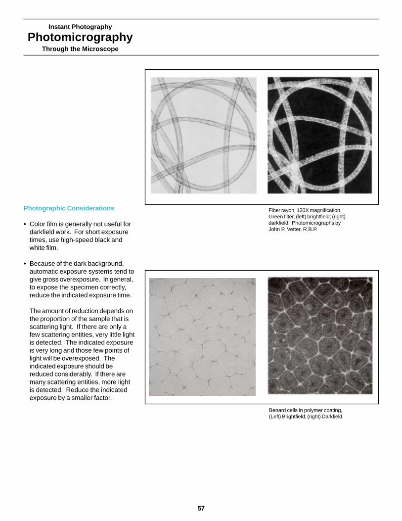
Instant Photography
PhotomicrographyThrough the Microscope
Photographic Considerations
• Color film is generally not useful fordarkfield work. For short exposuretimes, use high-speed black andwhite film.
• Because of the dark background,automatic exposure systems tend togive gross overexposure. In general,to expose the specimen correctly,reduce the indicated exposure time.
The amount of reduction depends onthe proportion of the sample that isscattering light. If there are only afew scattering entities, very little lightis detected. The indicated exposureis very long and those few points oflight will be overexposed. Theindicated exposure should bereduced considerably. If there aremany scattering entities, more lightis detected. Reduce the indicatedexposure by a smaller factor.
Fiber rayon, 120X magnification,Green filter, (left) brightfield; (right)darkfield. Photomicrographs byJohn P. Vetter, R.B.P.
Benard cells in polymer coating,(Left) Brightfield; (right) Darkfield.
57

Instant Photography
PhotomicrographyThrough the Microscope
58
The Physics of Phase-Contrast
Phase-contrast relies on theinterference between the directilluminating beam, as defined by theannular ring, and the light deflected(refracted or diffracted) by the differentparts of the specimen.
The deflected image-forming lightexperiences phase differences causedby the various parts of the specimen.The phase-changing ring introduces auniform phase change to theundeflected beam.
The phase-changing ring also reducesthe intensity of the direct illuminatingbeam, so that the direct and thescattered light beams are of relativelyequal intensity. This enables them tointerfere effectively.
The direct illuminating beam and thedeflected light beam interfere whenthey recombine at the eyepiece. Thisinterference changes the effective lightintensity from the various specimenparts to enhance image contrast.This technique is not for makingdimensional measurements of animage, because phase-contrast tendsto cause disturbing diffraction haloswithin the image.
Techniques
• In aligning the system, the circularimage of the direct illuminating beammust be superimposed accurately onthe phase-changing ring to achieveenhanced contrast.
• For easy alignment, use a phasetelescope in the place of one of theeyepieces to view a magnified imageof the back focal plane of theobjective.
• Clean the slide and coverslipthoroughly, as dirt could contributeunwanted and misleading phaseinformation to the image.
• Halo effects, characteristic of phase-contrast, may conceal usefulinformation. Use a mounting mediumof appropriate refractive index tolessen halo effects. Changing themounting medium can also affectimage contrast.
Phase-Contrast Illumination
Purpose
• To increase contrast and revealstructural detail in a cell or otherspecimen where very slightdifferences in thickness and refractiveindex are normally invisible
• To record a bright image on a darkerbackground
• To record a relatively dark image on abrighter background, depending onthe phase optics
Suitable Specimens
Usually very thin and colorless:• Blood cells
• Protozoa
• Tissue cultures
• Bacteria
• Yeasts
• Molds
• Diatoms
• Latex dispersions
• Glass fragments
• Replicas
Equipment
• Annular ring in the condenser
• Phase-changing ring in the backfocal plane of the objective lens
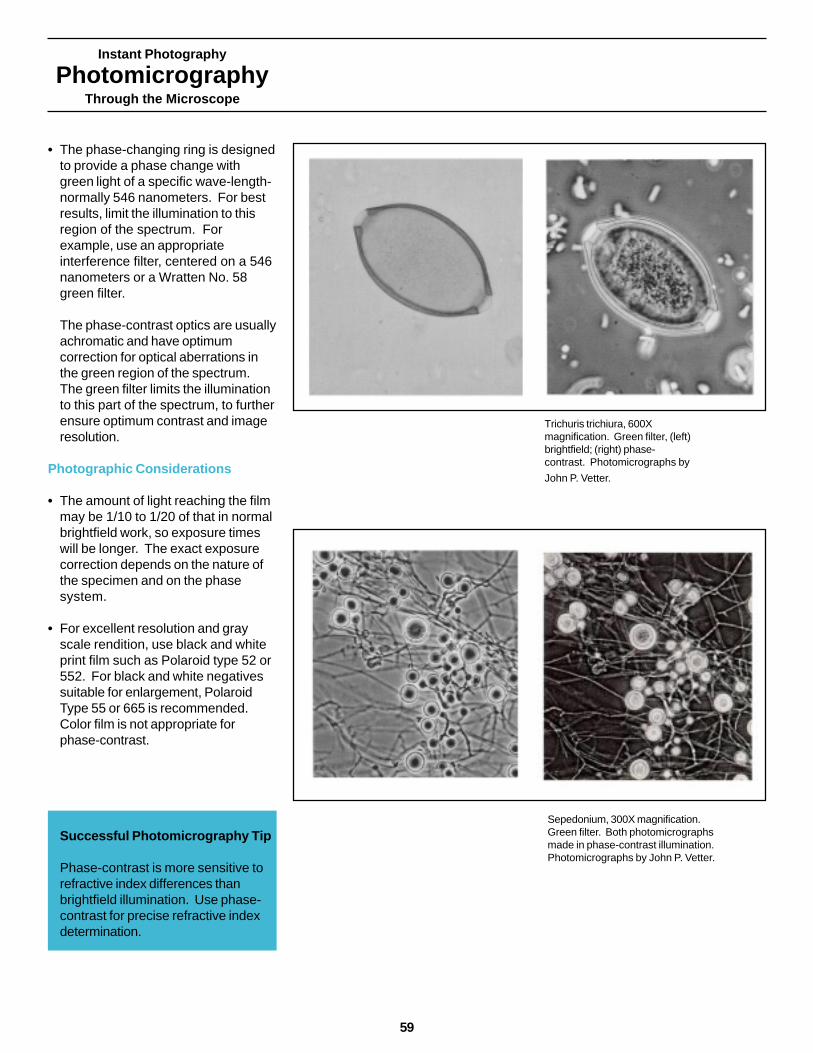
Instant Photography
PhotomicrographyThrough the Microscope
• The phase-changing ring is designedto provide a phase change withgreen light of a specific wave-length-normally 546 nanometers. For bestresults, limit the illumination to thisregion of the spectrum. Forexample, use an appropriateinterference filter, centered on a 546nanometers or a Wratten No. 58green filter.
The phase-contrast optics are usuallyachromatic and have optimumcorrection for optical aberrations inthe green region of the spectrum.The green filter limits the illuminationto this part of the spectrum, to furtherensure optimum contrast and imageresolution.
Photographic Considerations
• The amount of light reaching the filmmay be 1/10 to 1/20 of that in normalbrightfield work, so exposure timeswill be longer. The exact exposurecorrection depends on the nature ofthe specimen and on the phasesystem.
• For excellent resolution and grayscale rendition, use black and whiteprint film such as Polaroid type 52 or552. For black and white negativessuitable for enlargement, PolaroidType 55 or 665 is recommended.Color film is not appropriate forphase-contrast.
Successful Photomicrography Tip
Phase-contrast is more sensitive torefractive index differences thanbrightfield illumination. Use phase-contrast for precise refractive indexdetermination.
Sepedonium, 300X magnification.Green filter. Both photomicrographsmade in phase-contrast illumination.Photomicrographs by John P. Vetter.
Trichuris trichiura, 600Xmagnification. Green filter, (left)brightfield; (right) phase-contrast. Photomicrographs by
John P. Vetter.
59
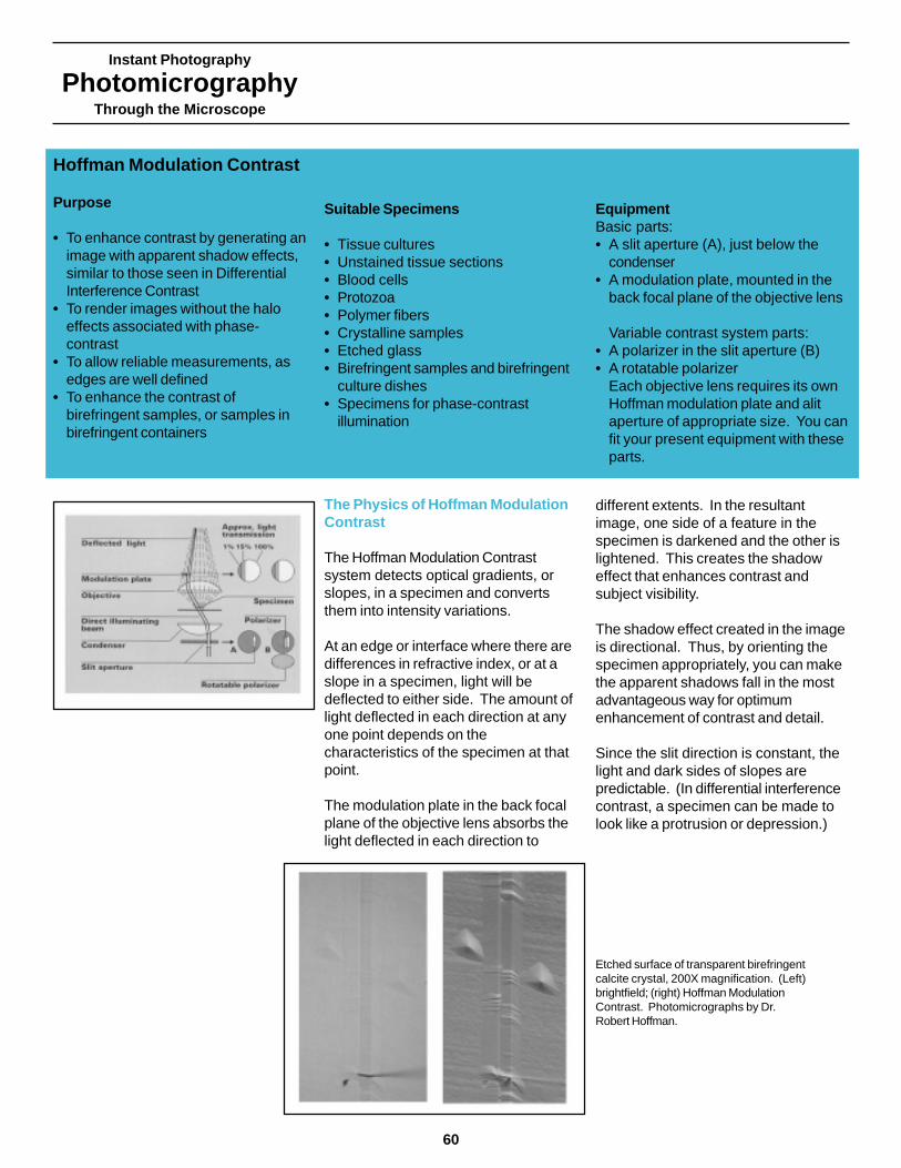
Instant Photography
PhotomicrographyThrough the Microscope
60
The Physics of Hoffman ModulationContrast
The Hoffman Modulation Contrastsystem detects optical gradients, orslopes, in a specimen and convertsthem into intensity variations.
At an edge or interface where there aredifferences in refractive index, or at aslope in a specimen, light will bedeflected to either side. The amount oflight deflected in each direction at anyone point depends on thecharacteristics of the specimen at thatpoint.
The modulation plate in the back focalplane of the objective lens absorbs thelight deflected in each direction to
different extents. In the resultantimage, one side of a feature in thespecimen is darkened and the other islightened. This creates the shadoweffect that enhances contrast andsubject visibility.
The shadow effect created in the imageis directional. Thus, by orienting thespecimen appropriately, you can makethe apparent shadows fall in the mostadvantageous way for optimumenhancement of contrast and detail.
Since the slit direction is constant, thelight and dark sides of slopes arepredictable. (In differential interferencecontrast, a specimen can be made tolook like a protrusion or depression.)
Hoffman Modulation Contrast
Purpose
• To enhance contrast by generating animage with apparent shadow effects,similar to those seen in DifferentialInterference Contrast
• To render images without the haloeffects associated with phase-contrast
• To allow reliable measurements, asedges are well defined
• To enhance the contrast ofbirefringent samples, or samples inbirefringent containers
Suitable Specimens
• Tissue cultures• Unstained tissue sections• Blood cells• Protozoa• Polymer fibers• Crystalline samples• Etched glass• Birefringent samples and birefringent
culture dishes• Specimens for phase-contrast
illumination
EquipmentBasic parts:• A slit aperture (A), just below the
condenser• A modulation plate, mounted in the
back focal plane of the objective lens
Variable contrast system parts:• A polarizer in the slit aperture (B)• A rotatable polarizer
Each objective lens requires its ownHoffman modulation plate and alitaperture of appropriate size. You canfit your present equipment with theseparts.
Etched surface of transparent birefringentcalcite crystal, 200X magnification. (Left)brightfield; (right) Hoffman ModulationContrast. Photomicrographs by Dr.Robert Hoffman.

Instant Photography
PhotomicrographyThrough the Microscope
Techniques
• Align your equipment so that thedesired illuminating beam from theslit (A) is imaged in the gray sectionof the modulation plate. Use a phasetelescope for easiest alignment.
• The variable contrast system (B)incorporates a polarizer in the slitaperture and a rotatable polarizerbelow. Rotate the polarizer to varythe size and intensity of the directilluminating beam to attain optimumcontrast for specimens having widelydiffering optical characteristics.
Photographic Considerations
• The amount of light reaching the filmmay be about 1/10 to 1/20 of thatavailable in normal brightfield work.The slit aperture reduces theillumination considerable and afurther reduction is caused byabsorption by the modulation plate.
• For excellent resolution and tonalrendition, use Polaroid Type 52, 552,57, or 667 film. Use an appropriateinterference filter or a green filter(such as the Wratten No. 58) foroptimum contrast and resolution.
• When using color film, omit thegreen filter. Use appropriate filtrationfor best color rendition.
• Depth of field is limited because ofthe relatively high numerical aperture.Therefore, selective focusing oroptical sectioning is possible throughthe thickness of a specimen.
Transparent replica of amicroelectronic circuit. 200Xmagnification. This pair ofHoffman Modulationphotomicrographs shows theeffect of specimen orientation.(Left) both horizontal and verticalchannels are clearly visible;(right) specimen having beenrotated by 45 degrees, thehorizontal channels are lost.
Live algae, 400X magnification.This pair of photomicrographsshows the effect of the polarizerin the slit aperture and therotatable polarizer just below.(Left) by fully crossing thepolarizers, very high contrastwas achieved: (right) as thepolarizers were uncrossed,contrast was reduced.Photomicrographs by Dr. RobertHoffman.
61
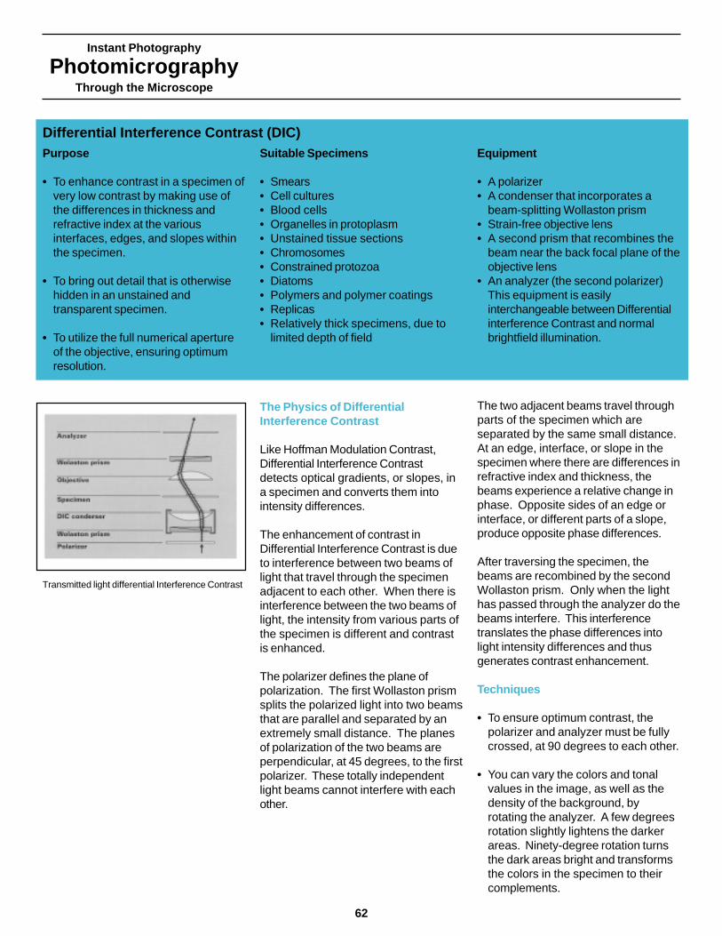
Instant Photography
PhotomicrographyThrough the Microscope
62
The Physics of DifferentialInterference Contrast
Like Hoffman Modulation Contrast,Differential Interference Contrastdetects optical gradients, or slopes, ina specimen and converts them intointensity differences.
The enhancement of contrast inDifferential Interference Contrast is dueto interference between two beams oflight that travel through the specimenadjacent to each other. When there isinterference between the two beams oflight, the intensity from various parts ofthe specimen is different and contrastis enhanced.
The polarizer defines the plane ofpolarization. The first Wollaston prismsplits the polarized light into two beamsthat are parallel and separated by anextremely small distance. The planesof polarization of the two beams areperpendicular, at 45 degrees, to the firstpolarizer. These totally independentlight beams cannot interfere with eachother.
The two adjacent beams travel throughparts of the specimen which areseparated by the same small distance.At an edge, interface, or slope in thespecimen where there are differences inrefractive index and thickness, thebeams experience a relative change inphase. Opposite sides of an edge orinterface, or different parts of a slope,produce opposite phase differences.
After traversing the specimen, thebeams are recombined by the secondWollaston prism. Only when the lighthas passed through the analyzer do thebeams interfere. This interferencetranslates the phase differences intolight intensity differences and thusgenerates contrast enhancement.
Techniques
• To ensure optimum contrast, thepolarizer and analyzer must be fullycrossed, at 90 degrees to each other.
• You can vary the colors and tonalvalues in the image, as well as thedensity of the background, byrotating the analyzer. A few degreesrotation slightly lightens the darkerareas. Ninety-degree rotation turnsthe dark areas bright and transformsthe colors in the specimen to theircomplements.
Purpose
• To enhance contrast in a specimen ofvery low contrast by making use ofthe differences in thickness andrefractive index at the variousinterfaces, edges, and slopes withinthe specimen.
• To bring out detail that is otherwisehidden in an unstained andtransparent specimen.
• To utilize the full numerical apertureof the objective, ensuring optimumresolution.
Suitable Specimens
• Smears• Cell cultures• Blood cells• Organelles in protoplasm• Unstained tissue sections• Chromosomes• Constrained protozoa• Diatoms• Polymers and polymer coatings• Replicas• Relatively thick specimens, due to
limited depth of field
Equipment
• A polarizer• A condenser that incorporates a
beam-splitting Wollaston prism• Strain-free objective lens• A second prism that recombines the
beam near the back focal plane of theobjective lens
• An analyzer (the second polarizer)This equipment is easilyinterchangeable between Differentialinterference Contrast and normalbrightfield illumination.
Differential Interference Contrast (DIC)
Transmitted light differential Interference Contrast

• Vary the phase difference to achievedifferent contrast and color effects bymaking a simple adjustment in one ofthe Wollaston prisms.
• The shadow effect created in theimage is unidirectional. Orient thespecimen so the shadows revealfeatures of interest.
• The sensitivity of DIC, and theplacement of the shadows on animage, can create the impression ofeither a protrusion or a depression.To prevent confusion, compare theshadows of unknown features withthose of known features.
• Birefringent specimens are generallynot suitable for DifferentialInterference Contrast because theyinterfere with the decisive polarizationof the light and produce a confusingimage.
Photographic Considerations
• For optimum resolution and contrastin black and white photomicrography,use a green filter, such as theWratten No. 58 or an appropriateinterference filter.
• With color film, which yieldsattractive and informative colorimages, use normal color filtrationand a didymium filter, whereappropriate. Do not use a green filter.
• The amount of light reaching the filmmay be from ½ to about 1/30 of thatavailable in normal brightfield work.The exact light reduction depends onthe amount of phase differenceintroduced and on the setting of thebeam-splitting Wollaston prism.
Instant Photography
PhotomicrographyThrough the Microscope
• Selective focusing, or opticalsectioning, is possible because theDifferential Interference Contrastmethod makes use of the fullnumerical aperture of the objectivelens, and the depth of the field is verylimited. Only the specimen planethat has been focused will be sharp.The remainder of the depth throughthe specimen will not be sharp andwill not intrude into the desiredimage.
Motor neuron, 160Xmagnification. Green filter.(Left) brightfield; (right)Differential Interference
Contrast.
Glass shards, in oil of 1,500refractive index. 200Xmagnification. Green (546 nm)interference filter. This pair ofphotomicrographs shows clearlythat, by making an appropriateadjustment in the setting of theWollaston prism, the apparent“shadow” created by theDifferential Interference Contrastmethod can be placed on either
side of the specimen.
63

Instant Photography
PhotomicrographyThrough the Microscope
64
Reflected Light DifferentialInterference Contrast
Differential Interference Contrast inreflected light requires a polarizer andanalyzer, a brightfield reflected lightobjective, a reflector, and a Wollastonprism which acts as both the beamsplitter and beam recombiner.
Slopes on the surface of the specimencreate the phase differences betweenadjacent beams, and lead to brightnessdifferences which delineate thetopography of the specimen.
To obtain the greatest contrast on thesamples with subtle slopes, adjust theprism so that the background is gray,with one slope dark and opposite slopebight.
The shadow effect in DIC isvariable, and the same feature canappear to be a depression or aprotrusion. (Left) features appearto be depressions, and (right) witha different setting of the beamsplitter, the same features appearto be protrusions.
Reflected light differential Interference Contrast
Uncoated surface of a diamond-turnedlens: The directional sensitivity of DICshows the grooves most clearly whenthey are oriented in the NW-SEdirection. The chatter marks whichare perpendicular to the grooves areshown most clearly when they are inthe same presentation.
Instant Photography
PhotomicrographyThrough the Microscope
TroubleshootingCommon Problems
Polaroid
65
Introduction
Many factors can affect image quality –improperly adjusted illumination oroptics; dirt, dust, or grease; or the useof the wrong filter. The following troubleshooting guide can help you correctcommon mistakes and betterunderstand the reasons behind them.
Basswood sternPolarized lightRed l PlatePolacolor ERType 59Mary McCann
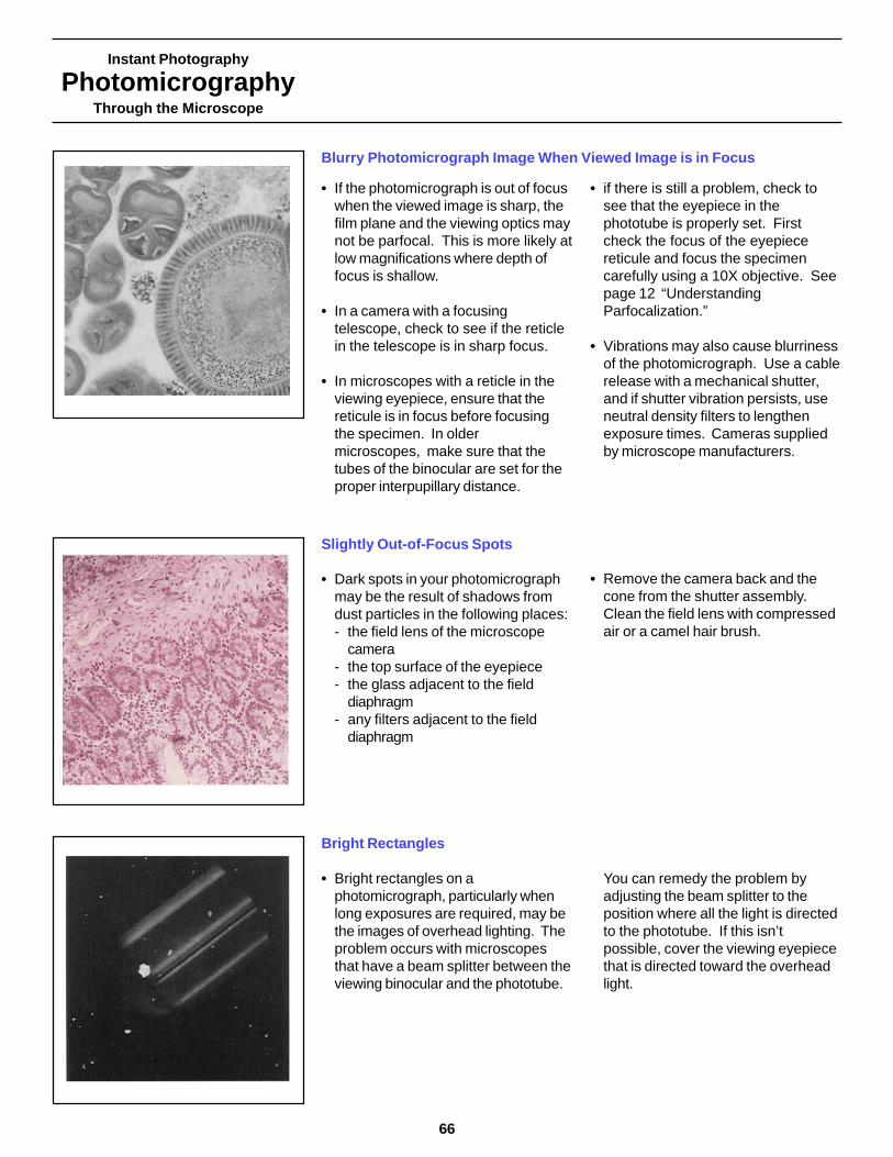
Instant Photography
PhotomicrographyThrough the Microscope
66
• If the photomicrograph is out of focuswhen the viewed image is sharp, thefilm plane and the viewing optics maynot be parfocal. This is more likely atlow magnifications where depth offocus is shallow.
• In a camera with a focusingtelescope, check to see if the reticlein the telescope is in sharp focus.
• In microscopes with a reticle in theviewing eyepiece, ensure that thereticule is in focus before focusingthe specimen. In oldermicroscopes, make sure that thetubes of the binocular are set for theproper interpupillary distance.
• if there is still a problem, check tosee that the eyepiece in thephototube is properly set. Firstcheck the focus of the eyepiecereticule and focus the specimencarefully using a 10X objective. Seepage 12 “UnderstandingParfocalization.”
• Vibrations may also cause blurrinessof the photomicrograph. Use a cablerelease with a mechanical shutter,and if shutter vibration persists, useneutral density filters to lengthenexposure times. Cameras suppliedby microscope manufacturers.
Blurry Photomicrograph Image When Viewed Image is in Focus
Slightly Out-of-Focus Spots
• Dark spots in your photomicrographmay be the result of shadows fromdust particles in the following places:- the field lens of the microscope
camera- the top surface of the eyepiece- the glass adjacent to the field
diaphragm- any filters adjacent to the field
diaphragm
• Remove the camera back and thecone from the shutter assembly.Clean the field lens with compressedair or a camel hair brush.
Bright Rectangles
• Bright rectangles on aphotomicrograph, particularly whenlong exposures are required, may bethe images of overhead lighting. Theproblem occurs with microscopesthat have a beam splitter between theviewing binocular and the phototube.
You can remedy the problem byadjusting the beam splitter to theposition where all the light is directedto the phototube. If this isn’tpossible, cover the viewing eyepiecethat is directed toward the overheadlight.

Instant Photography
PhotomicrographyThrough the Microscope
Blurring of Viewed Image
• If your image is blurry, there may befingerprints or grease on the font ofthe objective lens. On the top lens ofthe eyepiece, or on the slide. Use avery small amount of solvent to cleanthese surfaces. (Avoid using toomuch solvent, as this may affect theobjective cement or the slide-mounting medium). Refer to yourmicroscope instruction book fordirections for cleaning lens surfaces.
• Improper adjustment of the opticsmay be the cause of blurring. Checkif either the field diaphragm or theaperture diaphragm is open too far ornot properly centered.
• Blurring may also result when thespecimen is too thick.
• If the photomicrograph shows gradualdarkening at the edge of the imagearea, check that the substagecondenser is properly aligned and themicroscope is properly set for Kohlerillumination. If the condenser isn’t setto its proper height, closing theaperture diaphragm can causedarkening at the edge of the field.The objective is usually set in a fixedposition, so center the substagecondenser with the field diaphragm.
• If you have centered the objectiveand the condenser, and theillumination is still uneven, checkthat the lamp filament is centered.
Sharply Focused, Dark Corners
• Check that the field diaphragm isopened sufficiently.
• If the corners of yourphotomicrograph are in focus butdark, check that the eyepiecemagnifications is sufficient to fill thefull diagonal. For example, thediagonal of a 4x5” photomicrographis 145 mm. Using a camera with a1X magnification factor, an
8X/21 mm field of view eyepiece willgive an image 168 mm in diameter,sufficient to fill the wholephotomicrograph. However, usingthis eyepiece with a cameramagnification factor of 0.8 willgive an image 134 mm in diameter.This eyepiece would be moreappropriate for the 3 1/4X 4 1/4” film.
Gradual Darkening at the Edge of the Image
67

Instant Photography
PhotomicrographyThrough the Microscope
68
• The average brightness of thespecimen may not be representativeof the brightness in the areas ofinterest. For example, if thespecimen has small dark features ona bright background, the image willbe underexposed. Use the spotmeter setting if available. If the meteraverages the whole field of view, setthe film speed indicator tocompensate. If the specimen isbright in a large dark surround, theimage will be overexposed. Use thespot meter setting if available, orincrease the film speed indicator to alower value to increase the exposure.
• If the image is sharp in the center butout of focus around the edges,ensure that you have a plan objective.A non-plan objective is not correctedfor curvature of field of the image andwill not give a sharp image across thetotal field of view.
• In reflected light samples, a focusedcenter but out-of-focus edges mayresult when the specimen is notmounted flat. Mount the specimenon a small amount of modeling clayto allow leveling.
• A high numerical aperture objectivewith an improper coverslip over thespecimen may lack contrast in aphotomicrograph due to sphericalaberration. Check the side of thebarrel of the objective to see whatcoverslip thickness is required(usually 0.17 mm, the thickness of a#1 1/2 coverslip). Ensure that youhave the correct thickness coverslipwhen you work with objectives ofhigh numerical aperture.
• Remember, reflected light objectivesusually need no coverslip. If acoverslip is used, the micrograph willlack contrast.
• Photomicrographs lack contrastwhen the substage diaphragm isopened too far. Close the substagediaphragm to reduce flare. Inreflected light, the settings of boththe field diaphragm and the aperturediaphragm affect contrast.
• When you use an automatic camerawith deeply colored filters and theresulting photomicrograph image iseither too light or too dark, thesensitivity of the camera photocellmay not be uniform across thespectrum. Keep a record of thephoto results with different colorfilters, and adjust the film speedindicator to compensate.
• If automatic exposure with polarizedlight varies with the presence of thepolarizer or the analyzer, thephotocell may be sensitive topolarization effects. Keep a record ofthe exposure adjustment necessaryor inquire about remedy frommicroscope manufacturer.
Image Too Light or Too Dark, Using an Automatic Camera
Lack of Contrast and Poor Sharpness
Concentric Areas In and Out of Focus
Instant Photography
PhotomicrographyThrough the Microscope
Instant Filmsfor Photomicrography
Polaroid
69
Copper screen plated withcopper, 100x PolaroidType 53 JoAnn H.Montoya
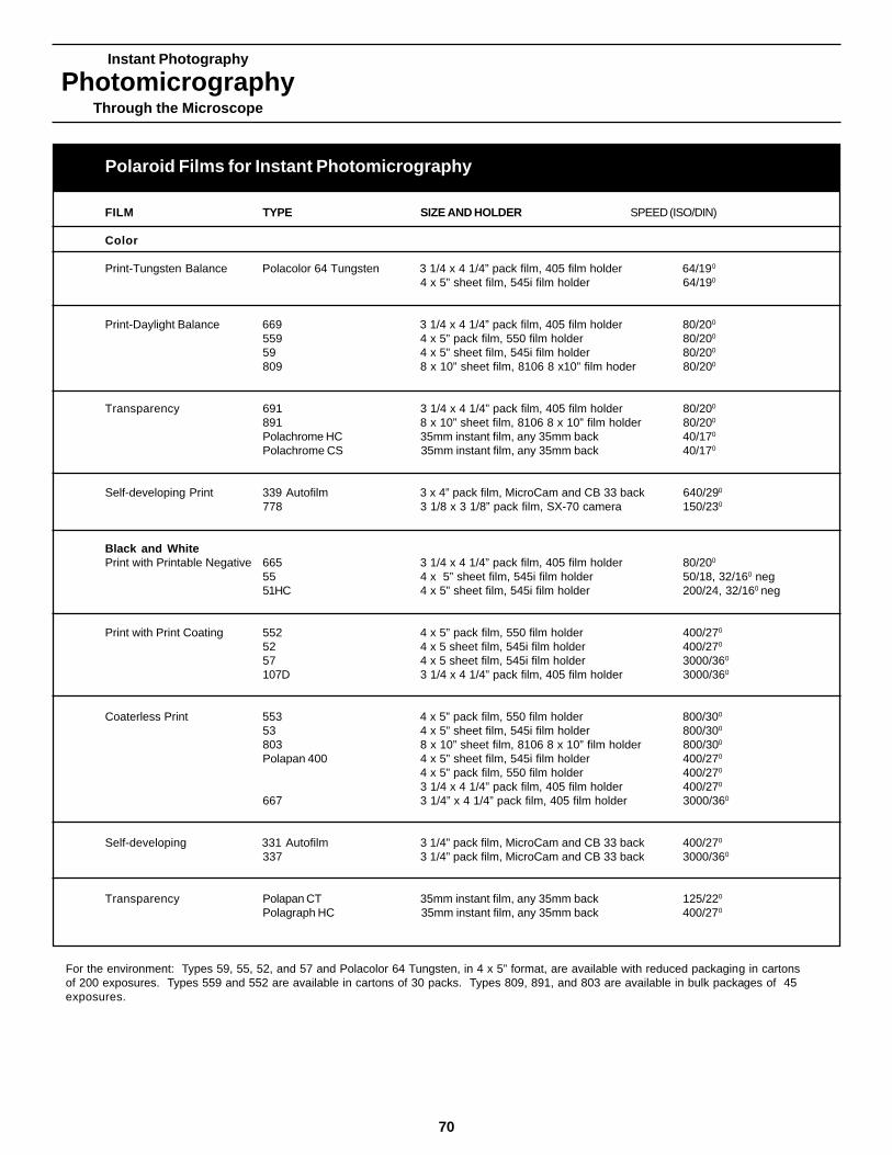
Instant Photography
PhotomicrographyThrough the Microscope
70
Polaroid Films for Instant Photomicrography
FILM TYPE SIZE AND HOLDER SPEED (ISO/DIN)
Color
Print-Tungsten Balance Polacolor 64 Tungsten 3 1/4 x 4 1/4” pack film, 405 film holder 64/190
4 x 5” sheet film, 545i film holder 64/190
Print-Daylight Balance 669 3 1/4 x 4 1/4” pack film, 405 film holder 80/200
559 4 x 5” pack film, 550 film holder 80/200
59 4 x 5” sheet film, 545i film holder 80/200
809 8 x 10” sheet film, 8106 8 x10” film hoder 80/200
Transparency 691 3 1/4 x 4 1/4” pack film, 405 film holder 80/200
891 8 x 10” sheet film, 8106 8 x 10” film holder 80/200
Polachrome HC 35mm instant film, any 35mm back 40/170
Polachrome CS 35mm instant film, any 35mm back 40/170
Self-developing Print 339 Autofilm 3 x 4” pack film, MicroCam and CB 33 back 640/290
778 3 1/8 x 3 1/8” pack film, SX-70 camera 150/230
Black and WhitePrint with Printable Negative 665 3 1/4 x 4 1/4” pack film, 405 film holder 80/200
55 4 x 5” sheet film, 545i film holder 50/18, 32/160 neg51HC 4 x 5” sheet film, 545i film holder 200/24, 32/160 neg
Print with Print Coating 552 4 x 5” pack film, 550 film holder 400/270
52 4 x 5 sheet film, 545i film holder 400/270
57 4 x 5 sheet film, 545i film holder 3000/360
107D 3 1/4 x 4 1/4” pack film, 405 film holder 3000/360
Coaterless Print 553 4 x 5” pack film, 550 film holder 800/300
53 4 x 5” sheet film, 545i film holder 800/300
803 8 x 10” sheet film, 8106 8 x 10” film holder 800/300
Polapan 400 4 x 5” sheet film, 545i film holder 400/270
4 x 5” pack film, 550 film holder 400/270
3 1/4 x 4 1/4” pack film, 405 film holder 400/270
667 3 1/4” x 4 1/4” pack film, 405 film holder 3000/360
Self-developing 331 Autofilm 3 1/4” pack film, MicroCam and CB 33 back 400/270
337 3 1/4” pack film, MicroCam and CB 33 back 3000/360
Transparency Polapan CT 35mm instant film, any 35mm back 125/220
Polagraph HC 35mm instant film, any 35mm back 400/270
For the environment: Types 59, 55, 52, and 57 and Polacolor 64 Tungsten, in 4 x 5” format, are available with reduced packaging in cartonsof 200 exposures. Types 559 and 552 are available in cartons of 30 packs. Types 809, 891, and 803 are available in bulk packages of 45exposures.

Instant Photography
PhotomicrographyThrough the Microscope
Medium 10-12 1p/mm No filtration necessary with tungsten illumination, exposures between1/2 and 8 seconds
Medium 10-12 lp/mm
Medium 10-12 lp/mm Filtration necessary (see your current film data sheet).Medium 10-12 lp/mmMedium 10-12 lp/mmMedium 10-12 lp/mm Requires Polaroid 8 x 10 film processor
Medium 10-12 lp/mm Same sensitivity as T669, daylight balancedMedium 10-12 lp/mm Requires Polaroid 8 x 10 film processorHigh 90 lp/mm Daylight balanced, requires Polaroid 35mm processorMedium 90 lp/mm Daylight balanced, requires Polaroid 35mm processor
Medium 90 lp/mm Daylight balanced, filtration necessary betwen 1/60 and 3 secondsMedium 8-10 lp/mm
Medium 22-25 print, 160-180 neg Fine grain print, high-resolution negativeMedium 20-25 print, 160-180 negHigh print, med. neg 20-23 print, 100-120 neg High-contrast print, high resolution negative
Medium 20-25 lp/mm Fine grain, good gray-scale renditionMedium 22-25 lp/mmMedium 16-22 lp/mm Exceptionally high-speed filmMedium 16-22 lp/mm
Medium 16-22 lp/mm Print does not require coatingMedium 16-22 lp/mmMedium 16-22 lp/mm Requires Polaroid 8 x 10 film processorMedium 20-22 lp/mm Same speed as Type 52, but does not require coatingMedium 20-22 lp/mmMedium 20-22 lp/mmMedium 16-22 lp/mm Exceptionallly high-speed film
Medium 20 lp/mm Self developing, self timingMedium 20 lp/mm
Medium 90 lp/mm Requires Polaroid 35mm film processorHigh 90 lp/mm High contrast, requires Polaroid 35mm film processor
CONTRAST RESOLUTION (LINE PAIRS/MM) SPEED CHARACTERISTICS
71
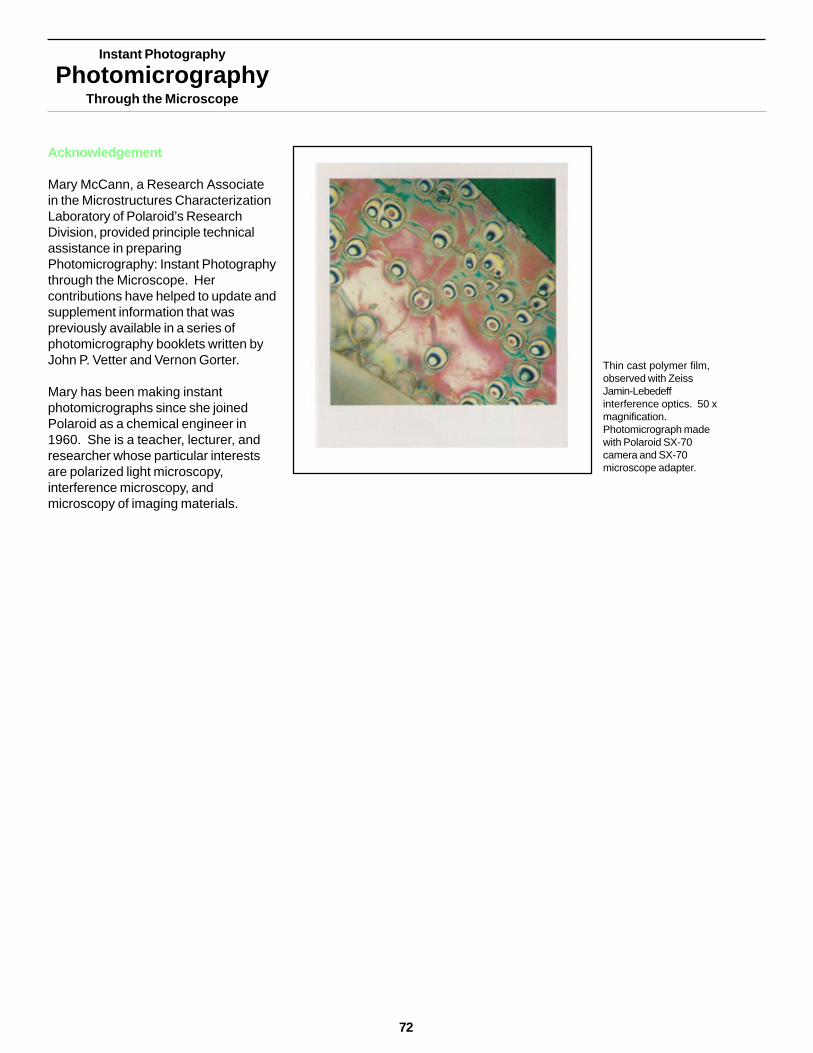
Acknowledgement
Mary McCann, a Research Associatein the Microstructures CharacterizationLaboratory of Polaroid’s ResearchDivision, provided principle technicalassistance in preparingPhotomicrography: Instant Photographythrough the Microscope. Hercontributions have helped to update andsupplement information that waspreviously available in a series ofphotomicrography booklets written byJohn P. Vetter and Vernon Gorter.
Mary has been making instantphotomicrographs since she joinedPolaroid as a chemical engineer in1960. She is a teacher, lecturer, andresearcher whose particular interestsare polarized light microscopy,interference microscopy, andmicroscopy of imaging materials.
Thin cast polymer film,observed with ZeissJamin-Lebedeffinterference optics. 50 xmagnification.Photomicrograph madewith Polaroid SX-70camera and SX-70microscope adapter.
Instant Photography
PhotomicrographyThrough the Microscope
72
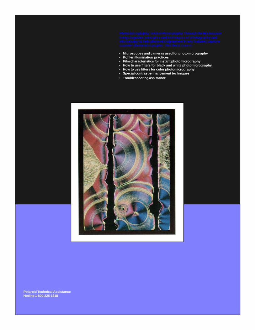
Photomicrography: Instant Photography Through the Microscopebrings together principles and techniques of photography andmicroscopy to help photomicrographers in any industry capturesuperior photomicrographs. This book covers:
• Microscopes and cameras used for photomicrography• Kohler illumination practices• Film characteristics for instant photomicrography• How to use filters for black and white photomicrography• How to use filters for color photomicrography• Special contrast-enhancement techniques• Troubleshooting assistance
Polaroid Technical AssistanceHotline 1-800-225-1618